Embed Size (px)
Citation preview
IPBrick - 6.1 VersionInstallation Manual
IPBRICK, S.A.
March 2016

2
Copyright c©IPBRICK, S.A.All rights reserved. March 2016.
The information in this manual is subject to change without prior notice. Thepresented explanations, technical data, configurations and recommendations areprecise and trustful. Nevertheless, they have no expressed or implied guarantees.
Installation Manual - 6.1 Version IPBRICK, S.A. - 2016

Contents
1 Purpose of this document 5
2 Before Getting Started 7
3 IPBRICK installation 93.1 Requirements . . . . . . . . . . . . . . . . . . . . . . . . . . . . . . 93.2 Installation Procedure . . . . . . . . . . . . . . . . . . . . . . . . . 93.3 Installer Boot menu . . . . . . . . . . . . . . . . . . . . . . . . . . . 10
3.3.1 Install . . . . . . . . . . . . . . . . . . . . . . . . . . . . . . 103.3.2 Upgrade/ReInstall . . . . . . . . . . . . . . . . . . . . . . . 103.3.3 Advanced Install . . . . . . . . . . . . . . . . . . . . . . . . 113.3.4 Create Bootable Pendrive . . . . . . . . . . . . . . . . . . . 153.3.5 Manual . . . . . . . . . . . . . . . . . . . . . . . . . . . . . 18
3.4 Regular Installation . . . . . . . . . . . . . . . . . . . . . . . . . . . 193.4.1 Graphical mode . . . . . . . . . . . . . . . . . . . . . . . . . 193.4.2 Text Mode . . . . . . . . . . . . . . . . . . . . . . . . . . . . 203.4.3 Auto Detection of Previous Installations . . . . . . . . . . . 22
3.5 Error Messages . . . . . . . . . . . . . . . . . . . . . . . . . . . . . 233.6 Customized Installation . . . . . . . . . . . . . . . . . . . . . . . . 23
3.6.1 Custom Partitioning . . . . . . . . . . . . . . . . . . . . . . 243.6.2 Software RAID installation . . . . . . . . . . . . . . . . . . . 24
4 Managing the IPBRICK 274.1 Network configuration . . . . . . . . . . . . . . . . . . . . . . . . . 274.2 Connecting to IPBRICK . . . . . . . . . . . . . . . . . . . . . . . . 27
4.2.1 Direct connection . . . . . . . . . . . . . . . . . . . . . . . . 284.2.2 Connecting through a hub or a switch . . . . . . . . . . . . 304.2.3 Network Connectivity Test . . . . . . . . . . . . . . . . . . . 31
4.3 Logins and Passwords . . . . . . . . . . . . . . . . . . . . . . . . . 324.3.1 IPBRICK - Web Interface (GUI) . . . . . . . . . . . . . . . 324.3.2 IPBRICK - Console . . . . . . . . . . . . . . . . . . . . . . . 324.3.3 IPBRICK - Email copy . . . . . . . . . . . . . . . . . . . . . 334.3.4 IPBRICK - Contacts . . . . . . . . . . . . . . . . . . . . . . 334.3.5 PostgreSQL - DataBase Server . . . . . . . . . . . . . . . . . 334.3.6 Anti-Spam . . . . . . . . . . . . . . . . . . . . . . . . . . . . 344.3.7 IPBRICKCAFE . . . . . . . . . . . . . . . . . . . . . . . . . 344.3.8 Groupware . . . . . . . . . . . . . . . . . . . . . . . . . . . . 35
IPBRICK, S.A. - 2016 Installation Manual - 6.1 Version

4 CONTENTS
4.3.9 IPBrick - Instant Messaging . . . . . . . . . . . . . . . . . . 354.3.10 IPBrick - Callmanager . . . . . . . . . . . . . . . . . . . . . 354.3.11 VOIP CDR . . . . . . . . . . . . . . . . . . . . . . . . . . . 35
5 More information 375.1 Technical Support . . . . . . . . . . . . . . . . . . . . . . . . . . . . 375.2 Useful Links . . . . . . . . . . . . . . . . . . . . . . . . . . . . . . . 37
6 Appendix A - Appliance IPBrick.GT 396.1 IPBBrick.GT connections . . . . . . . . . . . . . . . . . . . . . . . 396.2 Analog communications . . . . . . . . . . . . . . . . . . . . . . . . 406.3 Digital communications . . . . . . . . . . . . . . . . . . . . . . . . . 40
6.3.1 BRI . . . . . . . . . . . . . . . . . . . . . . . . . . . . . . . 416.3.2 PRI . . . . . . . . . . . . . . . . . . . . . . . . . . . . . . . 42
7 Appendix B - Disaster Recovery 477.1 USB recovery . . . . . . . . . . . . . . . . . . . . . . . . . . . . . . 47
7.1.1 USB renaming . . . . . . . . . . . . . . . . . . . . . . . . . . 477.1.2 USB pen formatting . . . . . . . . . . . . . . . . . . . . . . 49
8 Appendix C - Important Procedures 518.1 Administrator user credentials . . . . . . . . . . . . . . . . . . . . . 538.2 System users credentials . . . . . . . . . . . . . . . . . . . . . . . . 548.3 System administrator credentials . . . . . . . . . . . . . . . . . . . 558.4 CAFE and PostGresSQL credentials . . . . . . . . . . . . . . . . . 568.5 Email alerts definition . . . . . . . . . . . . . . . . . . . . . . . . . 568.6 Email for sending system settings . . . . . . . . . . . . . . . . . . . 588.7 Email for sending the databases backups notification . . . . . . . . 598.8 Services you want to provide on this server . . . . . . . . . . . . . . 60
Installation Manual - 6.1 Version IPBRICK, S.A. - 2016

Chapter 1
Purpose of this document
This manual contains important and useful instructions about IPBrick installa-tion procedure and endeavors to guide you through all the necessary steps to itscompletion.
IPBRICK, S.A. - 2016 Installation Manual - 6.1 Version

6 Purpose of this document
Installation Manual - 6.1 Version IPBRICK, S.A. - 2016

Chapter 2
Before Getting Started
Please note:
• When booting from the IPBrick DVD, the software installation begins im-mediately.
• The DHCP server will be inactive after the IPBrick installation. So, if youwish to access IPBRICK with a laptop you will need to activate it (for moreinfo, please consult subsection - 4.2.1 Direct Connection of this document).
• IPBrick v6.1 comes with a native browser (for more info, please consultsection - 4.2 Connecting to IPBRICK of this document).
IPBRICK, S.A. - 2016 Installation Manual - 6.1 Version

8 Before Getting Started
Installation Manual - 6.1 Version IPBRICK, S.A. - 2016

Chapter 3
IPBrick installation
The installation of an IPBrick server is made using a single DVD.
3.1 Requirements
• IPBrick installation DVD (Bootable DVD);
• PC x86-64;
• Minimum 2GB of RAM;
• HDD: a minimum of 20GB of disk space (total size of the hard disk drive);
• BIOS Bootable via DVD support;
• Network interface card (Ethernet 100Base-TX).
3.2 Installation Procedure
1. Insert the IPBrick bootable DVD into the machine’s DVD-Rom drive;
2. Enable booting from DVD on the machine BIOS;
3. Boot the machine using the IPBrick auto install DVD;
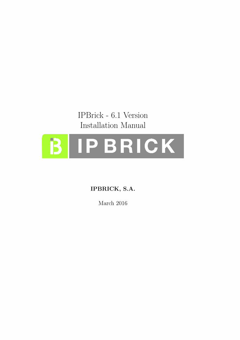
4. The IPBrick logo will appear and also a Installer Boot Menu.
IPBRICK, S.A. - 2016 Installation Manual - 6.1 Version
10 IPBrick installation
5. Ten seconds later the automatic installation process starts.
Note: If you want to stop the auto-install timer, please press any key.
3.3 Installer Boot menu
The boot menu is a very simple and intuitive way to custom manage yourIPBRICK installation. Just navigate with the Up and Down cursor buttonsand click on Enter to select the highlighted option.
3.3.1 Install
This option is the default option is equivalent to initiating the automaticinstallation procedure. This process is described in Section 3.4 - Regular In-stallation Procedure. IPBRICK auto-detects any previous OS (please checkSection - 3.4.3 of this document) prompts you to proceed first with dataand application backup. This option also offers a high degree of data lossprevention.
3.3.2 Upgrade/ReInstall
This installation option only applies to scenarios with a previous IPBRICKinstallation. As a matter of fact, IPBRICK auto-detects (please check Sec-tion - 3.4.3 of this document) any previous version and prompts you toproceed first with data and application backup. This option also offers a
Installation Manual - 6.1 Version IPBRICK, S.A. - 2016
3.3 Installer Boot menu 11
high degree of data loss prevention.
IMPORTANT NOTE: This option uses the IPBrick v6.0 default file sys-tem (EXT4), but previous installations may have different file systems, suchas, XFS or EXT3. In these cases, the previous data partitions will be keptwhile the system partitions will be formatted in EXT4.
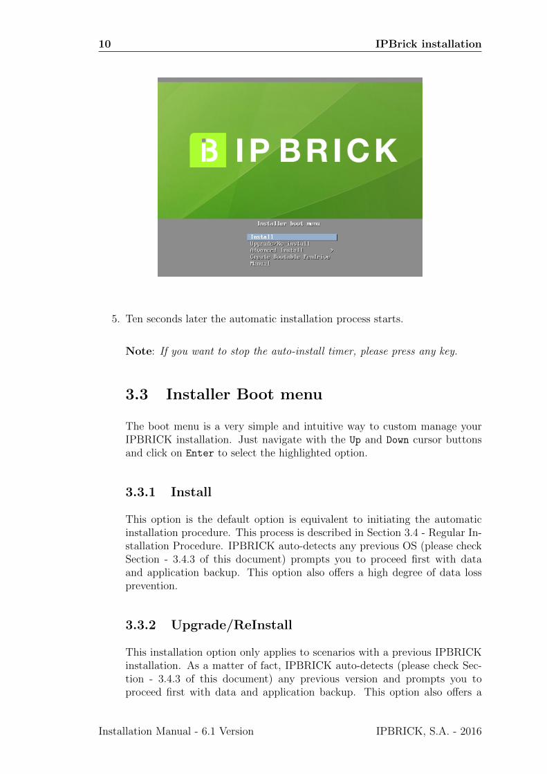
3.3.3 Advanced Install
As the name suggests, this option gives you the ability to customize IP-BRICK’s installation. It offers you new options, that are described in thefollowing sections of this document.
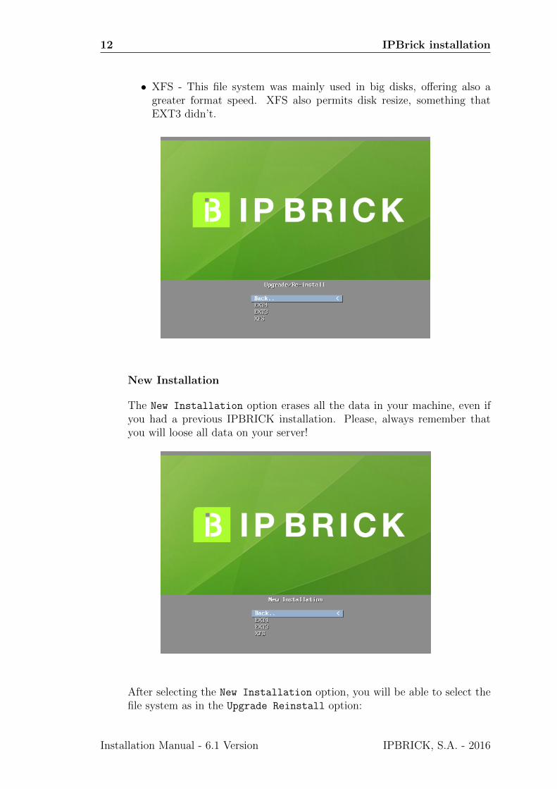
Upgrade/ReInstall
This other Upgrade/ReInstall option also enables you to keep a previousinstallation data. The installation will keep data from home1 and home2 par-titions, as well as data from databases.
The difference is in that you will have the possibility to select the file systemtype:
• EXT3 - In order to maintain coherence with previous default file sys-tems, EXT3 is included;
• EXT4 - This is the default setting. EXT4 is the natural evolution fromthe EXT3, offering you more features: Resize capability as well as thepossibility to use greater capacity discs, something that EXT3 didn’t;
IPBRICK, S.A. - 2016 Installation Manual - 6.1 Version
12 IPBrick installation
• XFS - This file system was mainly used in big disks, offering also agreater format speed. XFS also permits disk resize, something thatEXT3 didn’t.
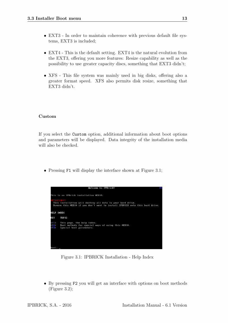
New Installation
The New Installation option erases all the data in your machine, even ifyou had a previous IPBRICK installation. Please, always remember thatyou will loose all data on your server!
After selecting the New Installation option, you will be able to select thefile system as in the Upgrade Reinstall option:
Installation Manual - 6.1 Version IPBRICK, S.A. - 2016
3.3 Installer Boot menu 13
• EXT3 - In order to maintain coherence with previous default file sys-tems, EXT3 is included;
• EXT4 - This is the default setting. EXT4 is the natural evolution fromthe EXT3, offering you more features: Resize capability as well as thepossibility to use greater capacity discs, something that EXT3 didn’t;
• XFS - This file system was mainly used in big disks, offering also agreater format speed. XFS also permits disk resize, something thatEXT3 didn’t.
Custom
If you select the Custom option, additional information about boot optionsand parameters will be displayed. Data integrity of the installation mediawill also be checked.
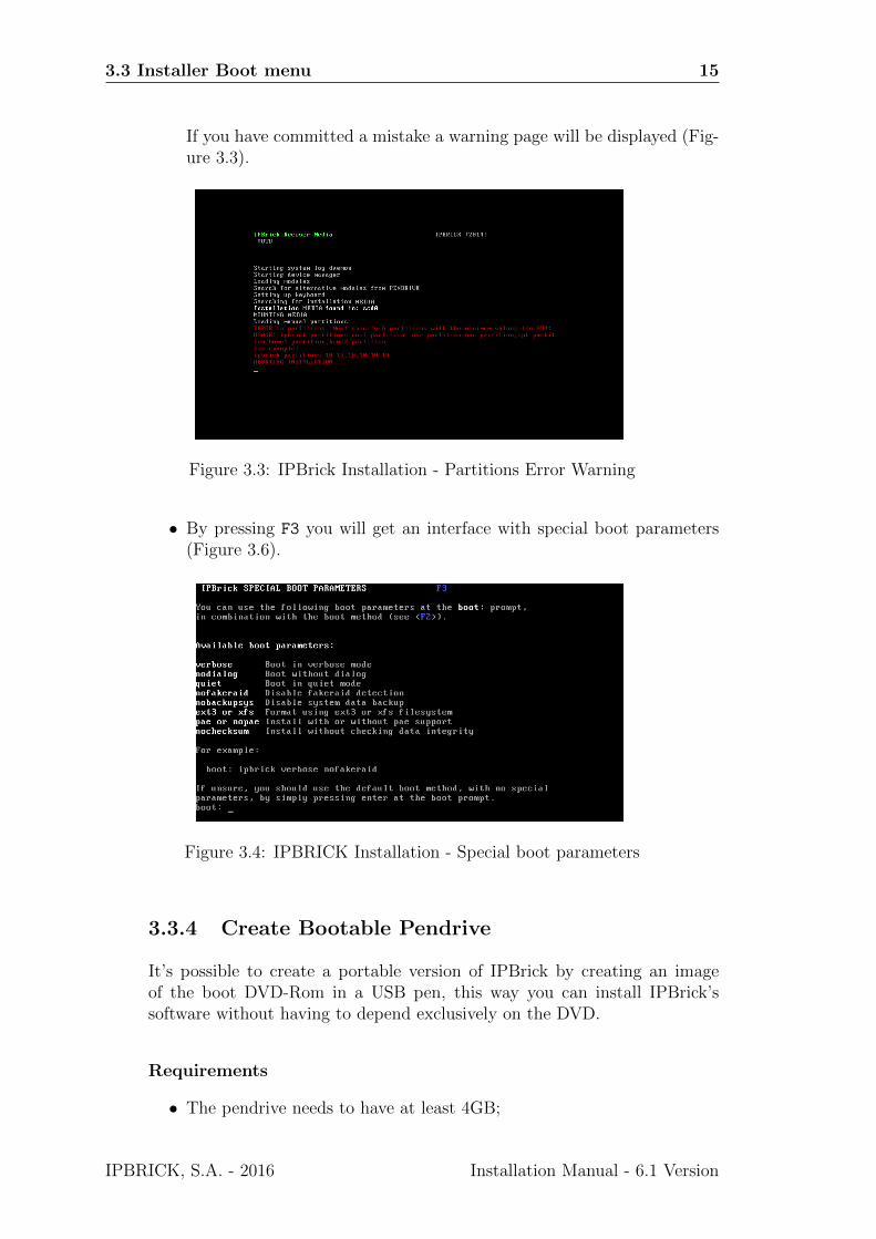
• Pressing F1 will display the interface shown at Figure 3.1;
Figure 3.1: IPBRICK Installation - Help Index
• By pressing F2 you will get an interface with options on boot methods(Figure 3.2);
IPBRICK, S.A. - 2016 Installation Manual - 6.1 Version

14 IPBrick installation
Figure 3.2: IPBRICK Installation - Boot methods
Partitions boot option
The partitions boot option. This feature enables you to allocate acustom size (in GB) to each of the following partitions:
1 root - equal or more than 2 GB
2 usr - equal or more than 4 GB
3 var - equal or more than 4 GB
4 opt - equal or more than 2 GB
5 home1 - equal or more than 1 GB
6 home2 - equal or more than 1 GB
Example:
If you have an 60GB HDD and want that each partition to have a sizeof 10GB, all you need to do is type:
ipbrick eraseall partitions=10,10,10,10,10,10
Each number separated by commas will be the partition size in GB.The order is as the one presented:
1 root
2 usr
3 var
4 opt
5 home1
6 home2
NOTE: If your disk capacity is 80GB and you type the exact same com-mand of 10GB, the remaining 20GB will be divided equally by home1
and home2
Installation Manual - 6.1 Version IPBRICK, S.A. - 2016
3.3 Installer Boot menu 15
If you have committed a mistake a warning page will be displayed (Fig-ure 3.3).
Figure 3.3: IPBrick Installation - Partitions Error Warning
• By pressing F3 you will get an interface with special boot parameters(Figure 3.6).
Figure 3.4: IPBRICK Installation - Special boot parameters
3.3.4 Create Bootable Pendrive
It’s possible to create a portable version of IPBrick by creating an imageof the boot DVD-Rom in a USB pen, this way you can install IPBrick’ssoftware without having to depend exclusively on the DVD.
Requirements
• The pendrive needs to have at least 4GB;
IPBRICK, S.A. - 2016 Installation Manual - 6.1 Version

16 IPBrick installation
• The pendrive must be formatted in the FAT32 file system;
• A machine with a USB slot.
Note: If you have in the pen any data you wish to keep, please save a copyelsewhere, because in order to mount the image the pen will be formatted andyou will loose all of its contents.
There are two ways to create a bootable pendrive:
(a) By using the UNetbootin tool (recommended);
(b) By using the IPBRICK DVD.
UNetbootin Procedure
The recommended procedure is to use the UNetbootin tool.
Firstly, you will need to download and install this tool at:
http://unetbootin.sourceforge.net/
NOTE: Beware that you need to download the correct OS version (Windows,Linux or Mac)!
Figure 3.5: UNetbootin OS versions
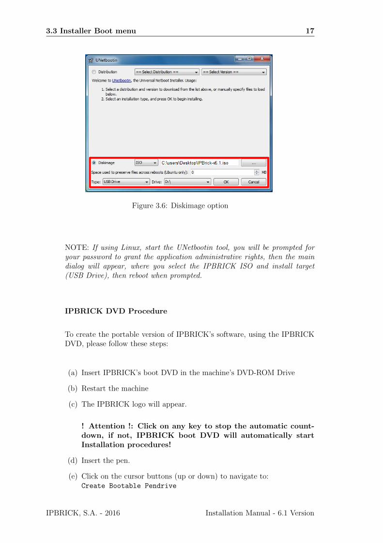
The procedure is similar in all OS versions you will just have to selectDiskimage instead of Distribution, browse for the IPBRICK ISO file byusing the ... button and select the select the target drive (USB Drive),then reboot once done.
IMPORTANT NOTE: Don’t forget that the pendrive must have, at least,4GB capacity and that it must be formatted in FAT32!
Installation Manual - 6.1 Version IPBRICK, S.A. - 2016
3.3 Installer Boot menu 17
Figure 3.6: Diskimage option
NOTE: If using Linux, start the UNetbootin tool, you will be prompted foryour password to grant the application administrative rights, then the maindialog will appear, where you select the IPBRICK ISO and install target(USB Drive), then reboot when prompted.
IPBRICK DVD Procedure
To create the portable version of IPBRICK’s software, using the IPBRICKDVD, please follow these steps:
(a) Insert IPBRICK’s boot DVD in the machine’s DVD-ROM Drive
(b) Restart the machine
(c) The IPBRICK logo will appear.
! Attention !: Click on any key to stop the automatic count-down, if not, IPBRICK boot DVD will automatically startInstallation procedures!
(d) Insert the pen.
(e) Click on the cursor buttons (up or down) to navigate to:Create Bootable Pendrive
IPBRICK, S.A. - 2016 Installation Manual - 6.1 Version
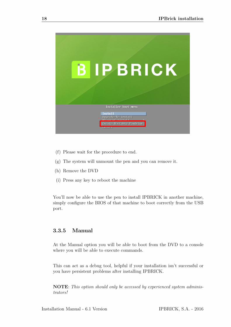
18 IPBrick installation
(f) Please wait for the procedure to end.
(g) The system will unmount the pen and you can remove it.
(h) Remove the DVD
(i) Press any key to reboot the machine
You’ll now be able to use the pen to install IPBRICK in another machine,simply configure the BIOS of that machine to boot correctly from the USBport.
3.3.5 Manual
At the Manual option you will be able to boot from the DVD to a consolewhere you will be able to execute commands.
This can act as a debug tool, helpful if your installation isn’t successful oryou have persistent problems after installing IPBRICK.
NOTE: This option should only be accessed by experienced system adminis-trators!
Installation Manual - 6.1 Version IPBRICK, S.A. - 2016
3.4 Regular Installation 19
3.4 Regular Installation
This regular installation is equivalent to the Install. As stated previously,When the timer reaches zero or when you choose the Install option at theboot menu, the regular installation procedure takes place.
By default, the installation runs in graphical mode with a progress bar, butthere is another mode, more textual, where every step is described.
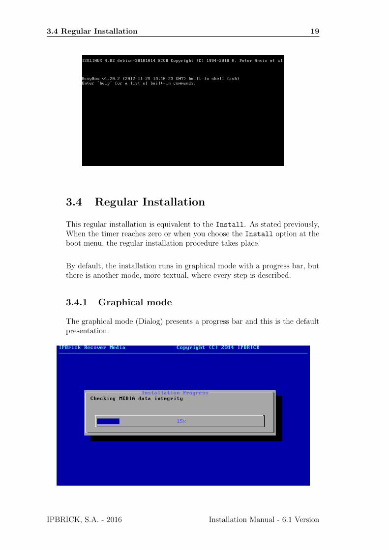
3.4.1 Graphical mode
The graphical mode (Dialog) presents a progress bar and this is the defaultpresentation.
IPBRICK, S.A. - 2016 Installation Manual - 6.1 Version

20 IPBrick installation
3.4.2 Text Mode
To select the text mode, you must choose the Custom option and typeipbrick no dialog as a special boot parameter (please check Subsection3.3.3 of this document for more info).
In text mode (no Dialog) the regular installation procedure performs theseactions:
• Warning regarding the beginning of the installation process.
• Kernel image loading.
• After startup, the auto-installation’s script will attempt to detect thecomputer’s hardware configuration where the IPBrick is being installed.
Starting system log daemon
Loading modules
Creating devices
Setting up keyboard
Searching MEDIA
MEDIA Found in: ___
MOUNTING MEDIA
6. After detecting all the hardware devices, a partition table will be created onthe hard drive.
STARTING HARD DISK DRIVE...
HDD FOUND
USING: ___
CHECKING DISK SIZE...
RESIZING HOMEs to FULL disk size
WRITING PARTITION TABLE TO HDD...
7. The auto install process starts once more, detecting that the partition tablehas already been applied to the disk.
HDD PARTITIONED
PROCEEDING WITH INSTALLATION
8. The partition preparation takes place.
FORMATTING HDD...
This step can take some time please wait...
FORMATTING PARTITION /dev/___1
FORMATTING PARTITION /dev/___3
FORMATTING PARTITION /dev/___5
FORMATTING PARTITION /dev/___6
FORMATTING PARTITION /dev/___7
Installation Manual - 6.1 Version IPBRICK, S.A. - 2016

3.4 Regular Installation 21
FORMATTING PARTITION /dev/___8
FORMATTING SWAP
MOUNTING NEW FILESYSTEM...
9. The software installation:
INSTALLING...
This step can take some time please wait...
INSTALLING DRIVE /media/data/drive1.dat
...
INSTALLING DRIVE /media/data/drive6.dat
CHECKING physical address extension support...
INSTALLING boot loader...
...
Boot loader installed.
...
System is now installed.
10. The installation process ends with the DVD-ROM’s ejection. Before ejection,the following message will be displayed:
UMOUNTING MEDIA
REMOVE MEDIA BEFORE REBOOTING YOUR SYSTEM
DO NOT RESTART SYSTEM WITH IPBRICK RECOVER MEDIA
UMOUNTING ALL
Installation scripts ENDED.
..
11. Remove the installation MEDIA and reboot the computer;
12. During the system boot make sure that the BIOS is configured to boot fromthe hard disk drive (HDD);
13. After the BIOS boot up sequence, it will display the boot loader (Grub);
14. Next, the kernel startup messages will appear. The kernel startup sequenceshould end with the following lines:
Debian GNU/Linux 4.0 ipbrick tty1
ipbrick login:
3.4.3 Auto Detection of Previous Installations
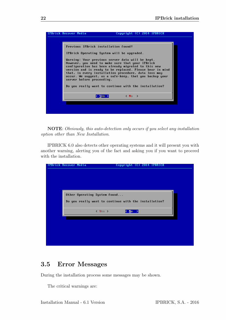
New in IPBRICK 6.0 is the ability to detect previous installations and perform theinstallation procedure while keeping the old server’s data. If there is a previousIPBRICK installation you will visualize a warning prompt as the one present inthe following picture. The default option is NO.
IPBRICK, S.A. - 2016 Installation Manual - 6.1 Version
22 IPBrick installation
NOTE: Obviously, this auto-detection only occurs if you select any installationoption other than New Installation.
IPBRICK 6.0 also detects other operating systems and it will present you withanother warning, alerting you of the fact and asking you if you want to proceedwith the installation.
3.5 Error Messages
During the installation process some messages may be shown.
The critical warnings are:
Installation Manual - 6.1 Version IPBRICK, S.A. - 2016

3.6 Customized Installation 23
• The installation scripts do not detect the MEDIA drive:
MEDIA NOT FOUND : Aborting INSTALL Scripts (NOT OK)
• The installation scripts do not detect the hard disk drive (HDD):
NO HARD DISK FOUND... (NOT OK)
ABORTING INSTALLATION... (NO HDD)
• The hard disk drive does not have the minimum size required:
NOT ENOUGH SPACE ON HDD
DISK SIZE: XXXX MegaBytes
NEEDED CAPACITY: YYYY MegaBytes
NOT ENOUGH SPACE ON HDD
NOTE: In old controllers the installation procedure may be interrupted. Inthese cases, there’s the possibility to run this command:
ipbrick eraseall smalldisk
This procedure uses the fdisk utility for disks with no more than 2TB ofmaximum space.
Critical errors are due to:
• Physical hardware failure: the disk does not exist or it has a wrong configu-ration (e.g: IDE bus, check for MASTER and/or SLAVE).
• Wrong BIOS configuration: Please check that the hardware is correctly con-figured (HDD, RAID controllers).
• If all of the above is correct, then the IPBrick CD that you have shouldn’tsupport your specific hardware configuration. Please send your hardwaredescription and configuration by mail to [email protected]. You will becontacted by the IPBrick Technical Department.
3.6 Customized Installation
If you insert a Pendrive into the server before installation, it’s possible to make acustomized installation of IPBrick.
IPBRICK, S.A. - 2016 Installation Manual - 6.1 Version
24 IPBrick installation
3.6.1 Custom Partitioning
Before the installation process, you need to create a file called parts.dat in thependrive root path, with the needed partition table structure (available for Down-load in the Documentation section). Next, the structure is presented in MB alongwith the explanation:
2000 -> Represents the /root partition.
1024 -> Represents the /swap partition.
4500 -> Represents the /usr partition.
2048 -> Do not change!
4000 -> Represents the /var partition.
2000 -> Represents the /opt partition.
100 -> Represents the /home1 partition. Minimum size
100 -> Represents the /home2 partition. Minimum size
7 -> Do not change!
The remaining disk space will be allocated in partitions /home1 and /home2.
3.6.2 Software RAID installation
With pendrive
You can have RAID1 configuration done by software. Before the installationprocess, you should create another file called system.cfg in the pendrive root path.Next, the structure is presented along with the explanation:
CONFIGSOFTRAID=1 -> Activates the software RAID
SOFTRAIDHDD[0]="sda" -> It’s the disk 1 device
SOFTRAIDHDD[1]="sdb" -> It’s the disk 2 device
SOFTRAIDPARTSUF="p" -> Do not change!
RAIDTYPE=1 -> It’s the RAID type. Only this raid type is supported!
You should know specifically the correct designation of hard drives devicesbefore the file creation, which depends of the used technology: IDE, SCSI, SATAetc.
NOTE: The RAID installation requires the system.cfg file that it is availablein our eshop.
Without pendrive
If you don’t have the pendrive root path, please proceed as follows:
• Boot the server with the DVD inserted;
• Select the option Manual on the Installation menu;
• Edit the configuration file system-install.cfg (e.g. /etc/system-install.cfg)
Installation Manual - 6.1 Version IPBRICK, S.A. - 2016
3.6 Customized Installation 25
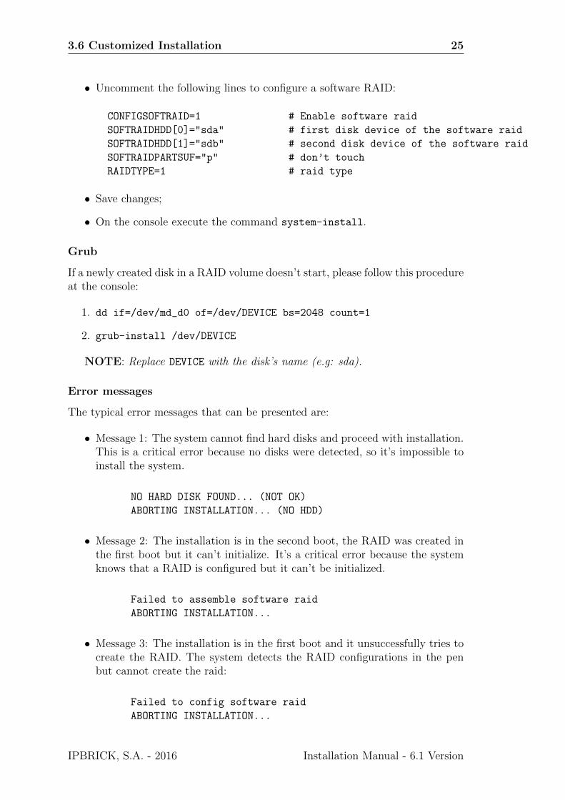
• Uncomment the following lines to configure a software RAID:
CONFIGSOFTRAID=1 # Enable software raid
SOFTRAIDHDD[0]="sda" # first disk device of the software raid
SOFTRAIDHDD[1]="sdb" # second disk device of the software raid
SOFTRAIDPARTSUF="p" # don’t touch
RAIDTYPE=1 # raid type
• Save changes;
• On the console execute the command system-install.
Grub
If a newly created disk in a RAID volume doesn’t start, please follow this procedureat the console:
1. dd if=/dev/md_d0 of=/dev/DEVICE bs=2048 count=1
2. grub-install /dev/DEVICE
NOTE: Replace DEVICE with the disk’s name (e.g: sda).
Error messages
The typical error messages that can be presented are:
• Message 1: The system cannot find hard disks and proceed with installation.This is a critical error because no disks were detected, so it’s impossible toinstall the system.
NO HARD DISK FOUND... (NOT OK)
ABORTING INSTALLATION... (NO HDD)
• Message 2: The installation is in the second boot, the RAID was created inthe first boot but it can’t initialize. It’s a critical error because the systemknows that a RAID is configured but it can’t be initialized.
Failed to assemble software raid
ABORTING INSTALLATION...
• Message 3: The installation is in the first boot and it unsuccessfully tries tocreate the RAID. The system detects the RAID configurations in the penbut cannot create the raid:
Failed to config software raid
ABORTING INSTALLATION...
IPBRICK, S.A. - 2016 Installation Manual - 6.1 Version

26 IPBrick installation
• Message 4: Here the installation is almost done and the Boot Loader is beingconfigured but the Boot Loader is not installed properly. So it can be critical- the machine could not boot because the Boot Loader was unsuccessfullyinstalled.
ERROR installing boot loader.
ABORTING INSTALLATION...
Note: The files must be saved in ASCII format. If you want to test that theyare, you can do file <filename> in Linux console.
Installation Manual - 6.1 Version IPBRICK, S.A. - 2016
Chapter 4
Managing the IPBrick
4.1 Network configuration
The IPBrick default network configurations are as follows:
• Private network interface card (eth0)
– IP: 192.168.69.199
– Network: 192.168.69.0/24
• Public network interface card (eth1)
– IP: 10.0.0.253
– Network: 10.0.0.252/30
• Gateway: 10.0.0.254 (eth1)
• Hostname: ipbrick.domain.com
4.2 Connecting to IPBrick
IPBRICK comes with a native browser so you can access it without having tobring a laptop or use another machine to access it. Very useful in virtual environ-ments. All it takes is a monitor, a mouse and a keyboard to implement the alwaysimportant first settings (Please consult Sections 4.3 - Logins and Passwords and 8- Important Procedures).
IPBRICK, S.A. - 2016 Installation Manual - 6.1 Version
28 Managing the IPBrick
Figure 4.1: IPBRICK Login
After logging in, you will find the always helpful Debug-Console icon, locatedat the top right hand corner of the screen. Note that, this icon only appears thefirst time you install IPBRICK, in the following accesses to the interface, this iconwill not be displayed. This icon also appears when the browser is open in theconsole. You may also click on it to close it.
Figure 4.2: Debug-Console icon
NOTE: This interface is presented every time you access it locally, but ifyou wish to access it from the console you may type the following command:gui-console start
4.2.1 Direct connection
In physical environments, you may wish to connect a crossover network cable tothe NIC of the management station (e.g. a laptop PC) and to the NIC on theIPBrick computer. (Figure8.33).
IMPORTANT NOTE: By default, IPBRICK v6.1 comes with the DHCPserver deactivated! In order to connect to the management station you will needto activate the DHCP server at:
Advanced Configurations > System > Services
Click on DHCP and alter the default settings to Enable (for more info, pleaseaccess section 8.8 - Services you want to provide on this server).
In this scenario, the network configuration of the management station may beset to receive automatic IP address and DNS configuration - DHCP client.
In the following configuration example we will be using a laptop computerinstalled with the MS Windows 7 operating sistem.
The configuration received from the DHCP is:
Installation Manual - 6.1 Version IPBRICK, S.A. - 2016
4.2 Connecting to IPBrick 29
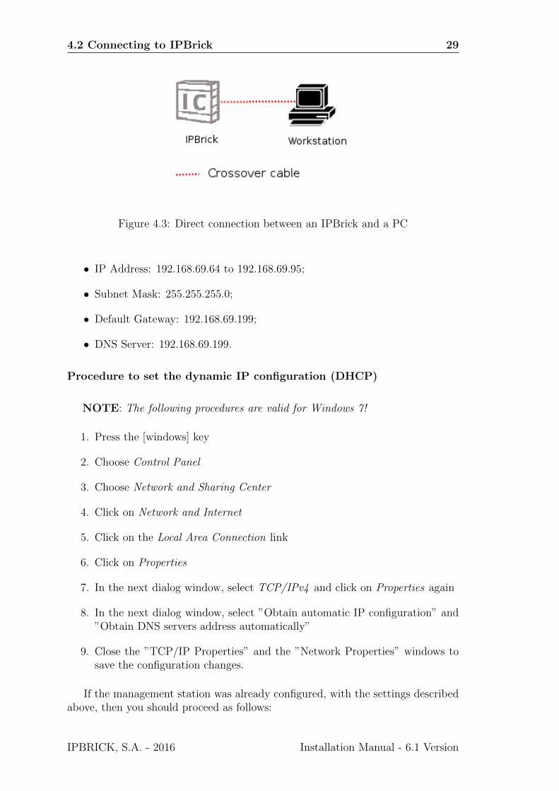
Figure 4.3: Direct connection between an IPBrick and a PC
• IP Address: 192.168.69.64 to 192.168.69.95;
• Subnet Mask: 255.255.255.0;
• Default Gateway: 192.168.69.199;
• DNS Server: 192.168.69.199.
Procedure to set the dynamic IP configuration (DHCP)
NOTE: The following procedures are valid for Windows 7!
1. Press the [windows] key
2. Choose Control Panel
3. Choose Network and Sharing Center
4. Click on Network and Internet
5. Click on the Local Area Connection link
6. Click on Properties
7. In the next dialog window, select TCP/IPv4 and click on Properties again
8. In the next dialog window, select ”Obtain automatic IP configuration” and”Obtain DNS servers address automatically”
9. Close the ”TCP/IP Properties” and the ”Network Properties” windows tosave the configuration changes.
If the management station was already configured, with the settings describedabove, then you should proceed as follows:
IPBRICK, S.A. - 2016 Installation Manual - 6.1 Version

30 Managing the IPBrick
Procedure to renew the IP address
1. Press keys [windows]+[R] (both at the same time)
2. Type cmd and press [ENTER] (or push the OK button)
3. Type ipconfig /release and press [ENTER]
4. Type ipconfig /renew and press [ENTER]
5. Type ipconfig /all and press [ENTER]
6. To close this window, type exit and press [ENTER]
To check your IP address, please proceed as follows:
How to check the IP address
1. Press keys [windows]+[R] (both at the same time)
2. Type cmd and press [ENTER]
3. Type ipconfig /all and press [ENTER]
4. To close this window, type exit and press [ENTER]
If at the end of this procedure you still don’t have an IP address like the onedescribed above:
1. Check for network connection (link, green light on) at the management sta-tion’s network interface card. If you don’t have a link, please check if yournetwork cable is in good shape and if it really is a crossover network cable.
2. If IPBrick computer has two network interface cards, please connect yournetwork cable to the other network interface card. Repeat the Procedureto renew the IP address.
4.2.2 Connecting through a hub or a switch
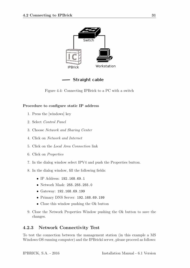
Connect IPBrick network interface card to a hub or to a switch (Figure4.4). Themanagement station must be connected to the same hub or switch (alternativelyone must assure connectivity from the management station to that hub or switch).
In the following example we will use a management station running MS Win-dows 7 operating system:
Installation Manual - 6.1 Version IPBRICK, S.A. - 2016
4.2 Connecting to IPBrick 31
Figure 4.4: Connecting IPBrick to a PC with a switch
Procedure to configure static IP address
1. Press the [windows] key
2. Select Control Panel
3. Choose Network and Sharing Center
4. Click on Network and Internet
5. Click on the Local Area Connection link
6. Click on Properties
7. In the dialog window select IPV4 and push the Properties button.
8. In the dialog window, fill the following fields:
• IP Address: 192.168.69.1
• Network Mask: 255.255.255.0
• Gateway: 192.168.69.199
• Primary DNS Server: 192.168.69.199
• Close this window pushing the Ok button
9. Close the Network Properties Window pushing the Ok button to save thechanges.
4.2.3 Network Connectivity Test
To test the connection between the management station (in this example a MSWindows OS running computer) and the IPBricks server, please proceed as follows:
IPBRICK, S.A. - 2016 Installation Manual - 6.1 Version
32 Managing the IPBrick
Procedure to test network connectivity
1. Press keys [windows]+[R] (both at the same time)
2. Type cmd and press [ENTER]
3. Type ping 192.168.69.199 and press [ENTER]
4. You should get the following lines from the ping utility:
Answer from 192.168.69.199: bytes=32 time<1ms TTL=64
Answer from 192.168.69.199: bytes=32 time<1ms TTL=64
Answer from 192.168.69.199: bytes=32 time<1ms TTL=64
Answer from 192.168.69.199: bytes=32 time<1ms TTL=64
Ping statistics for 192.168.69.199:
Packets: Sent = 4, Received = 4, Lost = 0
5. To close this window, type exit and press [ENTER]
With the connection set, the IPBrick server may be accessed using any webbrowser (e.g.: MS Internet Explorer (10 or later versions), Firefox, Chrome).The URL address is : https://ipbrick.domain.com or https://192.168.69.199.
4.3 Logins and Passwords
IMPORTANT NOTE: The authentication credentials presented next are thesystem’s default logins and passwords. Needless to say that, after the installationprocedure, you must alter them. Not complying with this directive opens a breachon your system’s security!!!
For information on this and other crucial after-installation first measures pleaseconsult section 8 Appendix C - Important Procedures.
4.3.1 IPBrick - Web Interface (GUI)
• URLhttps://192.168.69.199
https://ipbrick.domain.com
• Name: admin
• Password: 123456
4.3.2 IPBrick - Console
• root : R0laBill
• operator: L1opardo
Installation Manual - 6.1 Version IPBRICK, S.A. - 2016
4.3 Logins and Passwords 33
4.3.3 IPBrick - Email copy
There are two email accounts destinated to the IPBrick received and sent messagesstorage. Initially the query (POP or IMAP) of this messages is done by:
Sent Email
• Login: sentmail
• Password: L1opardo
Received Email
• Login: receivedmail
• Password: L1opardo
Note: After the IPBrick installation this service is not active, but it can be ac-tivated later through the web interface in IPBrick.C- >> E-Mail >> Mail Copy.
4.3.4 IPBrick - Contacts
• URLhttp://contacts.domain.com
• Login and administration password:administrator : 123
The access to this service is initially limited to the ”administrator” user. Thisuser will grant access and permissions to the other IPBrick users. Each user shoulduse its own login and password to authenticate.
4.3.5 PostgreSQL - DataBase Server
• URLhttp://pgsqladmin.domain.com
• Login and administration password:sqlserver : sqlserver
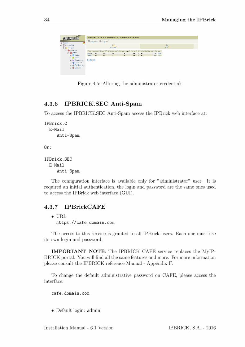
To change the the default passwords on PgSQLadmin, please access the interface:
pgsqladmin.domain.com - On the left side of the screen, click on PostgreSQL(use the default login: sqlserver and the default password: sqlserver).
Click on the Roles tab and then on the Alter to change the password forpostgres and sqlserver
IPBRICK, S.A. - 2016 Installation Manual - 6.1 Version
34 Managing the IPBrick
Figure 4.5: Altering the administrator credentials
4.3.6 IPBRICK.SEC Anti-Spam
To access the IPBRICK.SEC Anti-Spam access the IPBrick web interface at:
IPBrick.C
Anti-Spam
Or:
IPBrick.SEC
Anti-Spam
The configuration interface is available only for ”administrator” user. It isrequired an initial authentication, the login and password are the same ones usedto access the IPBrick web interface (GUI).
4.3.7 IPBrickCAFE
• URLhttps://cafe.domain.com
The access to this service is granted to all IPBrick users. Each one must useits own login and password.
IMPORTANT NOTE: The IPBRICK CAFE service replaces the MyIP-BRICK portal. You will find all the same features and more. For more informationplease consult the IPBRICK reference Manual - Appendix F.
To change the default administrative password on CAFE, please access theinterface:
cafe.domain.com
• Default login: admin
Installation Manual - 6.1 Version IPBRICK, S.A. - 2016
4.3 Logins and Passwords 35
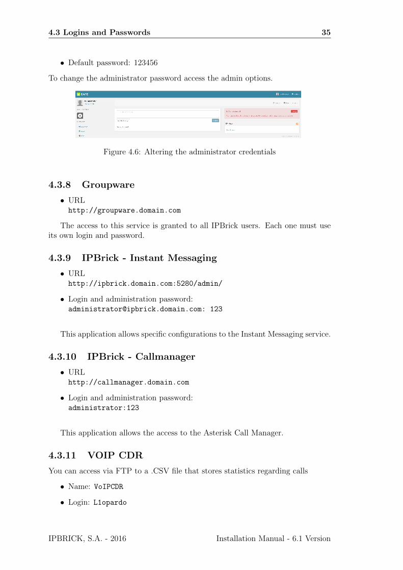
• Default password: 123456
To change the administrator password access the admin options.
Figure 4.6: Altering the administrator credentials
4.3.8 Groupware
• URLhttp://groupware.domain.com
The access to this service is granted to all IPBrick users. Each one must useits own login and password.
4.3.9 IPBrick - Instant Messaging
• URLhttp://ipbrick.domain.com:5280/admin/
• Login and administration password:[email protected]: 123
This application allows specific configurations to the Instant Messaging service.
4.3.10 IPBrick - Callmanager
• URLhttp://callmanager.domain.com
• Login and administration password:administrator:123
This application allows the access to the Asterisk Call Manager.
4.3.11 VOIP CDR
You can access via FTP to a .CSV file that stores statistics regarding calls
• Name: VoIPCDR
• Login: L1opardo
IPBRICK, S.A. - 2016 Installation Manual - 6.1 Version

36 Managing the IPBrick
Installation Manual - 6.1 Version IPBRICK, S.A. - 2016

Chapter 5
More information
5.1 Technical Support
To contact IPBrick technical support, please send an e-mail to:[email protected].
5.2 Useful Links
• www.ipbrick.com
• www.iportaldoc.com
IPBRICK, S.A. - 2016 Installation Manual - 6.1 Version

38 More information
Installation Manual - 6.1 Version IPBRICK, S.A. - 2016
Chapter 6
Appendix A - ApplianceIPBrick.GT
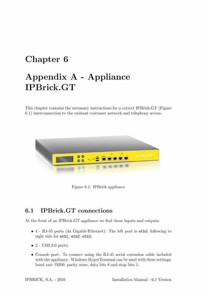
This chapter contains the necessary instructions for a correct IPBrick.GT (Figure6.1) interconnection to the existant costumer network and telephony access.
Figure 6.1: IPBrick appliance
6.1 IPBrick.GT connections
At the front of an IPBrick.GT appliance we find these inputs and outputs:
• 4 - RJ-45 ports (4x Gigabit-Ethernet): The left port is eth0, following toright side for eth1, eth2, eth3;
• 2 - USB 2.0 ports;
• Console port: To connect using the RJ-45 serial extension cable includedwith the appliance. Windows HyperTerminal can be used with these settings:baud rate 19200, parity none, data bits 8 and stop bits 1;
IPBRICK, S.A. - 2016 Installation Manual - 6.1 Version

40 Appendix A - Appliance IPBrick.GT
• Display: A .deb package can be installed at IPBrick to show the ether-net/telephony cards port status;
At the back of an IPBrick.GT appliance we have:
• 2 PCI slots for telephony cards;
• A power switch;
6.2 Analog communications
In case of analogic telephony accesses/lines, IPBrick.GT can have a card as theone visible at Figure 6.2. This card can have different modules inserted:
• FXS: Foreign eXchange Subscriber interface, to connect to telephones, modems,FAX’s etc (GREEN MODULES);
• FXO: Foreign eXchange Office interface, to connect to PSTN (RED MOD-ULES);
At Figure 6.2 example, the two first interfaces are FXS and the last two areFXO. It’s possible to see the connection between the module and the specific port.If you want to connect phones to the FXS ports, those ports should be poweredon using the PW interface showed at Figure 6.2.
Note: The card jumpers should not be changed. The physical link is RJ-11.
Figure 6.2: Analog telephony card
6.3 Digital communications
In case of digital lines, IPBrick.GT cards can be ISDN BRI or ISDN PRI.
Installation Manual - 6.1 Version IPBRICK, S.A. - 2016
6.3 Digital communications 41
6.3.1 BRI
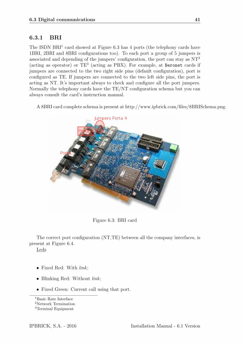
The ISDN BRI1 card showed at Figure 6.3 has 4 ports (the telephony cards have1BRI, 2BRI and 8BRI configurations too). To each port a group of 5 jumpers isassociated and depending of the jumpers’ configuration, the port can stay as NT2
(acting as operator) or TE3 (acting as PBX). For example, at Beronet cards ifjumpers are connected to the two right side pins (default configuration), port isconfigured as TE. If jumpers are connected to the two left side pins, the port isacting as NT. It’s important always to check and configure all the port jumpers.Normally the telephony cards have the TE/NT configuration schema but you canalways consult the card’s instruction manual.
A 8BRI card complete schema is present at http://www.ipbrick.com/files/8BRISchema.png.
Figure 6.3: BRI card
The correct port configuration (NT,TE) between all the company interfaces, ispresent at Figure 6.4.
Leds
• Fixed Red: With link ;
• Blinking Red: Without link ;
• Fixed Green: Current call using that port.
1Basic Rate Interface2Network Termination3Terminal Equipment
IPBRICK, S.A. - 2016 Installation Manual - 6.1 Version
42 Appendix A - Appliance IPBrick.GT
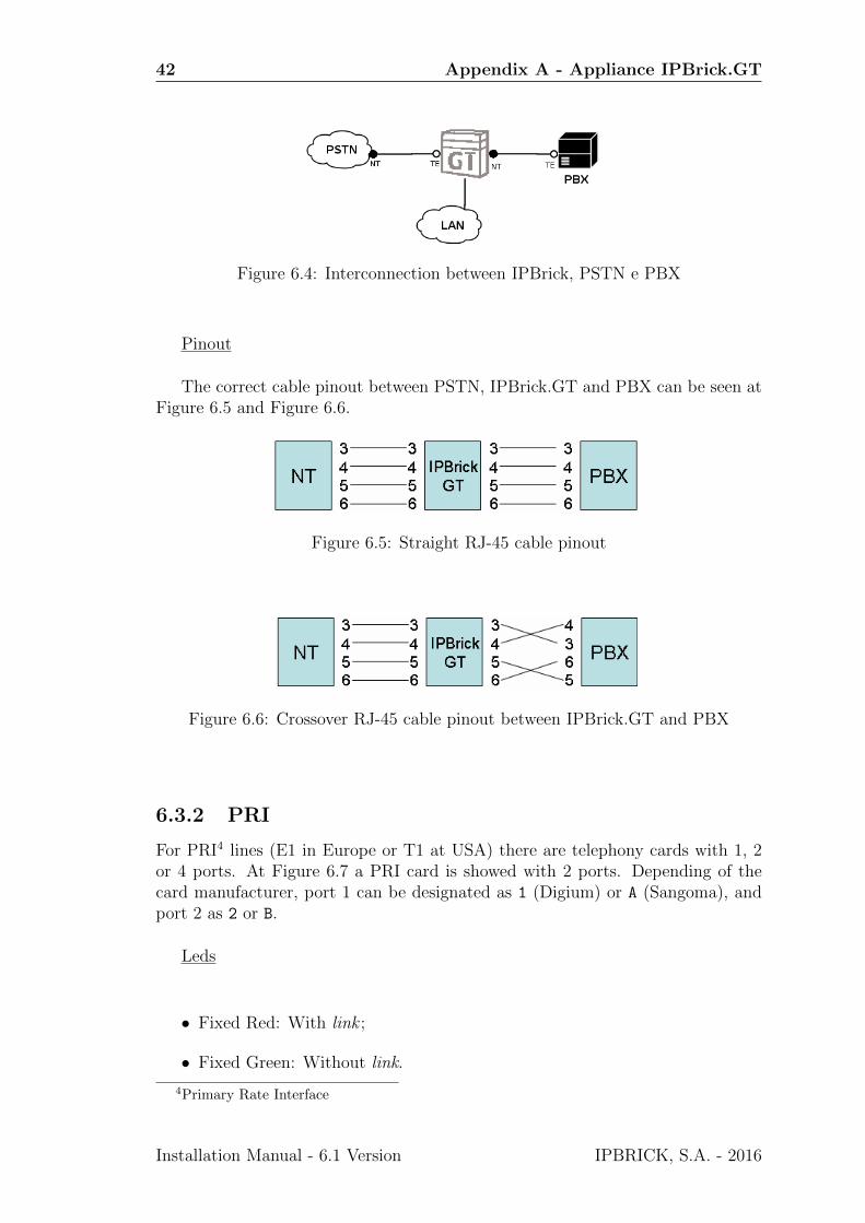
Figure 6.4: Interconnection between IPBrick, PSTN e PBX
Pinout
The correct cable pinout between PSTN, IPBrick.GT and PBX can be seen atFigure 6.5 and Figure 6.6.
Figure 6.5: Straight RJ-45 cable pinout
Figure 6.6: Crossover RJ-45 cable pinout between IPBrick.GT and PBX
6.3.2 PRI
For PRI4 lines (E1 in Europe or T1 at USA) there are telephony cards with 1, 2or 4 ports. At Figure 6.7 a PRI card is showed with 2 ports. Depending of thecard manufacturer, port 1 can be designated as 1 (Digium) or A (Sangoma), andport 2 as 2 or B.
Leds
• Fixed Red: With link ;
• Fixed Green: Without link.
4Primary Rate Interface
Installation Manual - 6.1 Version IPBRICK, S.A. - 2016

6.3 Digital communications 43
Figure 6.7: PRI card
Pinout
The correct cable pinout between PSTN, IPBrick.GT and PBX can be seen atFigure 6.8.
Figure 6.8: Crossover RJ-45 cable pinout between IPBrick.GT and PBX
The connection between the PRI modem and the existant PBX can use:
• Coaxial cables: Two coaxial cables (send and receive) are connected betweenthe PRI modem and the PBX (Figure 6.10). The connector is usually BNCbut different types of BNC connectors are used, depending of the operator.
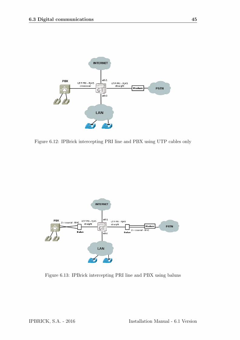
• UTP cables: One PRI UTP cable connected between the PRI modem andthe PBX using RJ-45 connectors (Figure 6.11)
Depending of that connection type, IPBrick can intercept that PBX/PSTNconnection using:
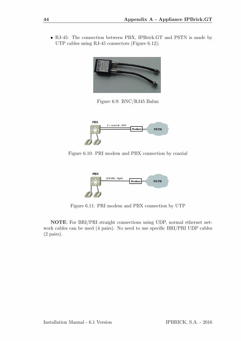
• balun (Figure 6.9) is a converter that can be plugged into by 2 coaxial cablesat one side (2 BNC’s), and at the other side a single RJ-45 cable can pluginto an IPBrick telephony card port. The connection schema can be viewedat Figure 6.13;
IPBRICK, S.A. - 2016 Installation Manual - 6.1 Version
44 Appendix A - Appliance IPBrick.GT
• RJ-45: The connection between PBX, IPBrick.GT and PSTN is made byUTP cables using RJ-45 connectors (Figure 6.12);
Figure 6.9: BNC/RJ45 Balun
Figure 6.10: PRI modem and PBX connection by coaxial
Figure 6.11: PRI modem and PBX connection by UTP
NOTE: For BRI/PRI straight connections using UDP, normal ethernet net-work cables can be used (4 pairs). No need to use specific BRI/PRI UDP cables(2 pairs).
Installation Manual - 6.1 Version IPBRICK, S.A. - 2016
6.3 Digital communications 45
Figure 6.12: IPBrick intercepting PRI line and PBX using UTP cables only
Figure 6.13: IPBrick intercepting PRI line and PBX using baluns
IPBRICK, S.A. - 2016 Installation Manual - 6.1 Version

46 Appendix A - Appliance IPBrick.GT
Installation Manual - 6.1 Version IPBRICK, S.A. - 2016

Chapter 7
Appendix B - Disaster Recovery
7.1 USB recovery
Immediately after installation IPBRICK will have a configuration called default
which is the IPBRICK’s base configuration.
All subsequent configurations done in IPBrick through the web interface aresaved in a Postgres database. This way any changes done will only be effective inthe system after clicking on Apply Configurations.
IPBRICK allows the time tracking of all configurations, because when youmodify something in the web interface and Apply Configurations, a new config-uration is locally saved. It is possible to store these configuration files in an USBpen and additionally send them to a configurable email address. In the filenamewe have the date and the exact hour when a configuration was created. In short,this configuration management allows a fast disaster recovery, in case of hardwareproblems.
! Attention !: After the IPBRICK installation you should always insert aUSB pen connected to server. The pen must be labeled with the name IPBRICK-D
and must be FAT32 formated.
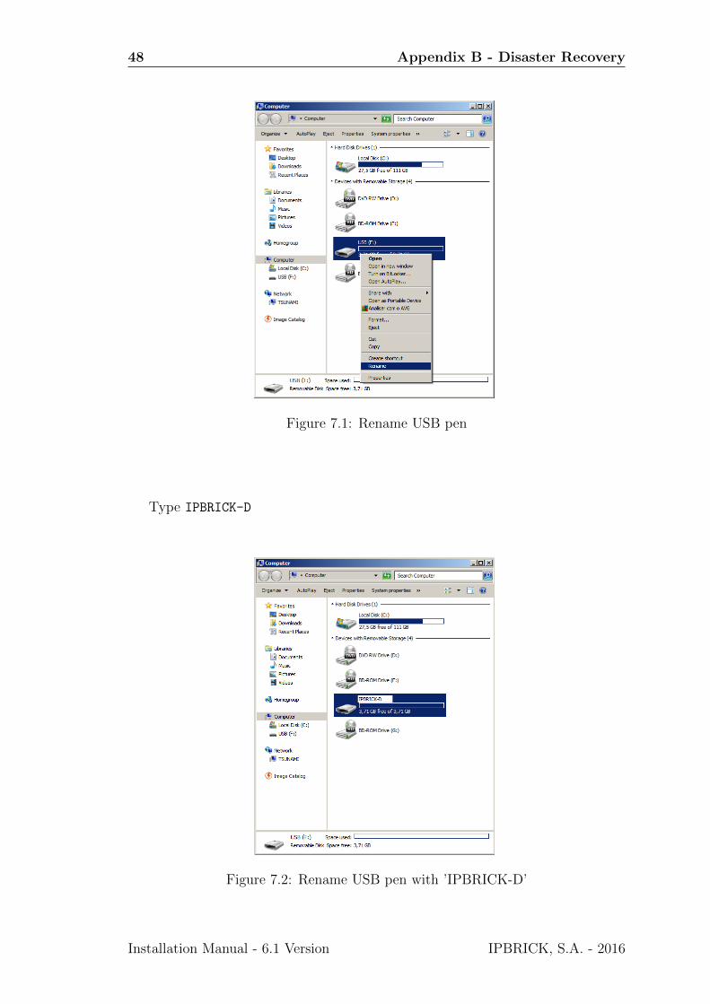
7.1.1 USB renaming
To rename your USB pen to IPBRICK-D simply do a right click on its icon inMy Computer and select Rename
IPBRICK, S.A. - 2016 Installation Manual - 6.1 Version
48 Appendix B - Disaster Recovery
Figure 7.1: Rename USB pen
Type IPBRICK-D
Figure 7.2: Rename USB pen with ’IPBRICK-D’
Installation Manual - 6.1 Version IPBRICK, S.A. - 2016
7.1 USB recovery 49
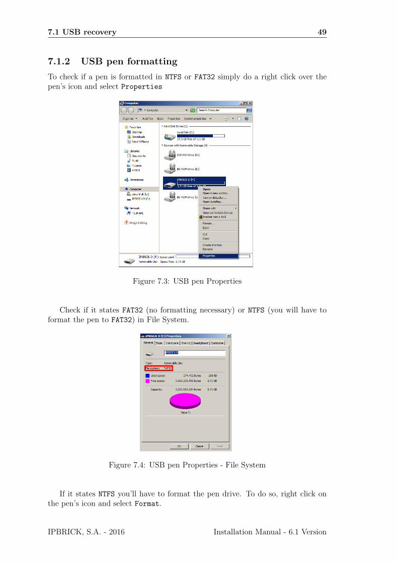
7.1.2 USB pen formatting
To check if a pen is formatted in NTFS or FAT32 simply do a right click over thepen’s icon and select Properties
Figure 7.3: USB pen Properties
Check if it states FAT32 (no formatting necessary) or NTFS (you will have toformat the pen to FAT32) in File System.
Figure 7.4: USB pen Properties - File System
If it states NTFS you’ll have to format the pen drive. To do so, right click onthe pen’s icon and select Format.
IPBRICK, S.A. - 2016 Installation Manual - 6.1 Version
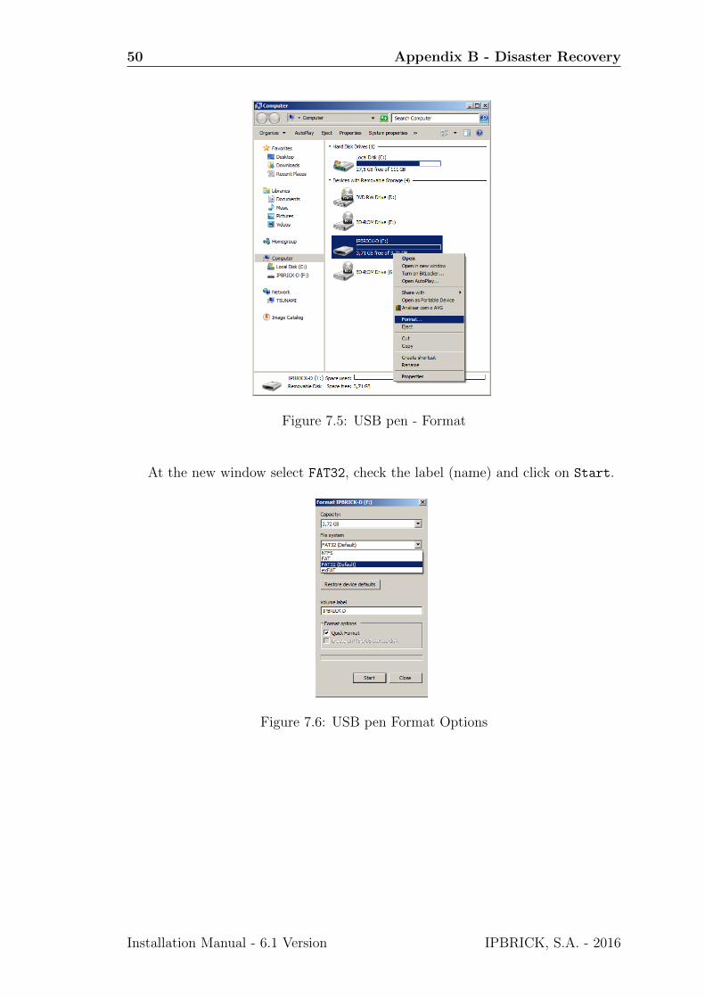
50 Appendix B - Disaster Recovery
Figure 7.5: USB pen - Format
At the new window select FAT32, check the label (name) and click on Start.
Figure 7.6: USB pen Format Options
Installation Manual - 6.1 Version IPBRICK, S.A. - 2016
Chapter 8
Appendix C - ImportantProcedures
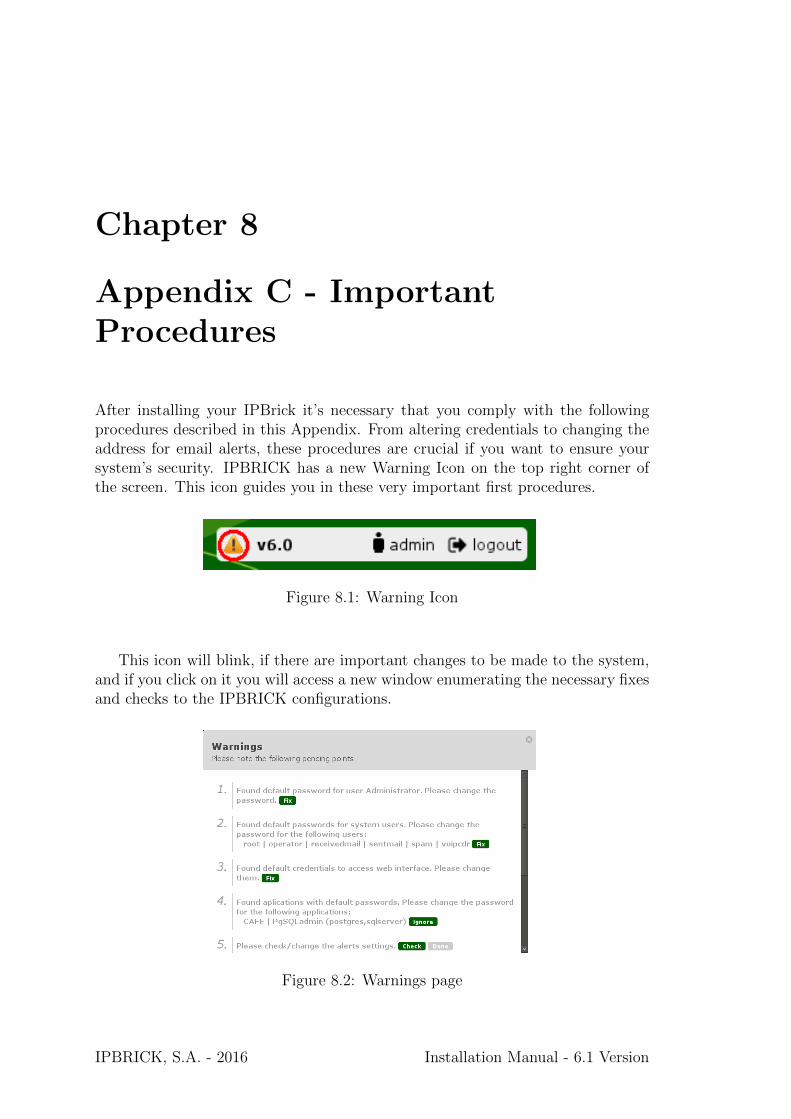
After installing your IPBrick it’s necessary that you comply with the followingprocedures described in this Appendix. From altering credentials to changing theaddress for email alerts, these procedures are crucial if you want to ensure yoursystem’s security. IPBRICK has a new Warning Icon on the top right corner ofthe screen. This icon guides you in these very important first procedures.
Figure 8.1: Warning Icon
This icon will blink, if there are important changes to be made to the system,and if you click on it you will access a new window enumerating the necessary fixesand checks to the IPBRICK configurations.
Figure 8.2: Warnings page
IPBRICK, S.A. - 2016 Installation Manual - 6.1 Version
52 Appendix C - Important Procedures
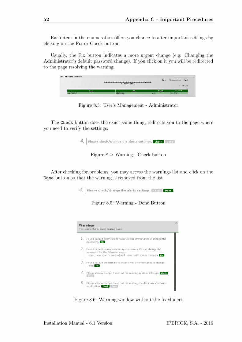
Each item in the enumeration offers you chance to alter important settings byclicking on the Fix or Check button.
Usually, the Fix button indicates a more urgent change (e.g: Changing theAdministrator’s default password change). If you click on it you will be redirectedto the page resolving the warning.
Figure 8.3: User’s Management - Administrator
The Check button does the exact same thing, redirects you to the page whereyou need to verify the settings.
Figure 8.4: Warning - Check button
After checking for problems, you may access the warnings list and click on theDone button so that the warning is removed from the list.
Figure 8.5: Warning - Done Button
Figure 8.6: Warning window without the fixed alert
Installation Manual - 6.1 Version IPBRICK, S.A. - 2016
8.1 Administrator user credentials 53
In the following sections we will address each of the necessary configurationsdisplayed on the alerts window.
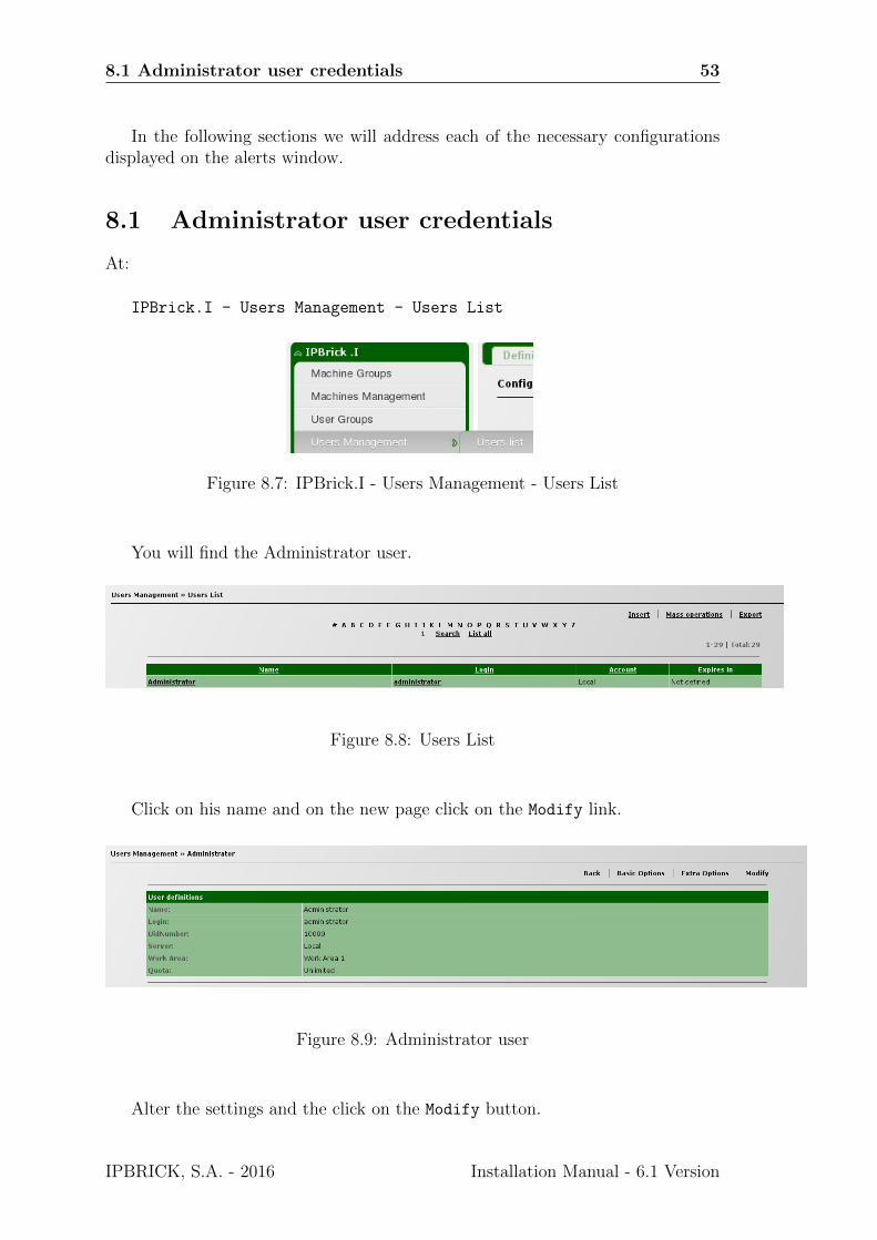
8.1 Administrator user credentials
At:
IPBrick.I - Users Management - Users List
Figure 8.7: IPBrick.I - Users Management - Users List
You will find the Administrator user.
Figure 8.8: Users List
Click on his name and on the new page click on the Modify link.
Figure 8.9: Administrator user
Alter the settings and the click on the Modify button.
IPBRICK, S.A. - 2016 Installation Manual - 6.1 Version
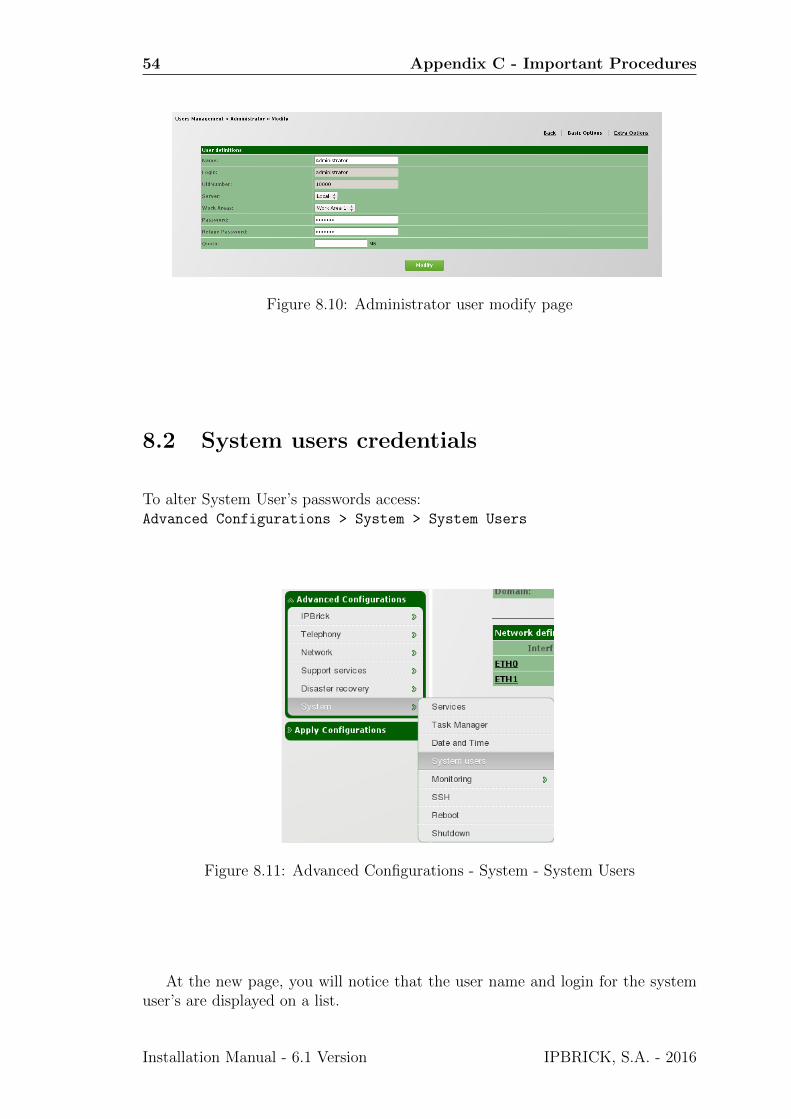
54 Appendix C - Important Procedures
Figure 8.10: Administrator user modify page
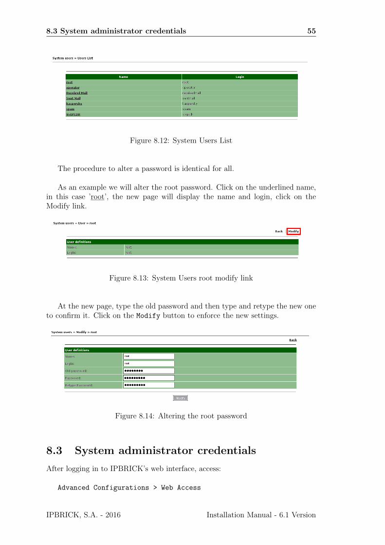
8.2 System users credentials
To alter System User’s passwords access:Advanced Configurations > System > System Users
Figure 8.11: Advanced Configurations - System - System Users
At the new page, you will notice that the user name and login for the systemuser’s are displayed on a list.
Installation Manual - 6.1 Version IPBRICK, S.A. - 2016
8.3 System administrator credentials 55
Figure 8.12: System Users List
The procedure to alter a password is identical for all.
As an example we will alter the root password. Click on the underlined name,in this case ’root’, the new page will display the name and login, click on theModify link.
Figure 8.13: System Users root modify link
At the new page, type the old password and then type and retype the new oneto confirm it. Click on the Modify button to enforce the new settings.
Figure 8.14: Altering the root password
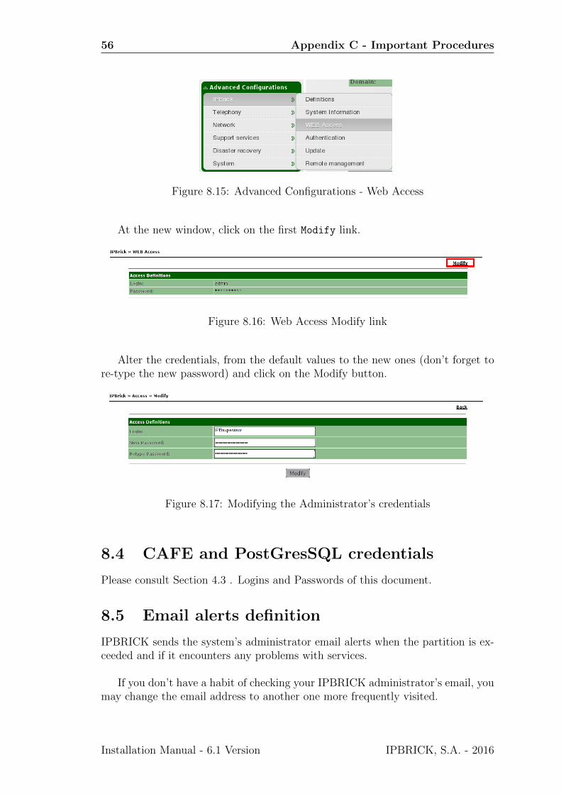
8.3 System administrator credentials
After logging in to IPBRICK’s web interface, access:
Advanced Configurations > Web Access
IPBRICK, S.A. - 2016 Installation Manual - 6.1 Version
56 Appendix C - Important Procedures
Figure 8.15: Advanced Configurations - Web Access
At the new window, click on the first Modify link.
Figure 8.16: Web Access Modify link
Alter the credentials, from the default values to the new ones (don’t forget tore-type the new password) and click on the Modify button.
Figure 8.17: Modifying the Administrator’s credentials
8.4 CAFE and PostGresSQL credentials
Please consult Section 4.3 . Logins and Passwords of this document.
8.5 Email alerts definition
IPBRICK sends the system’s administrator email alerts when the partition is ex-ceeded and if it encounters any problems with services.
If you don’t have a habit of checking your IPBRICK administrator’s email, youmay change the email address to another one more frequently visited.
Installation Manual - 6.1 Version IPBRICK, S.A. - 2016
8.5 Email alerts definition 57
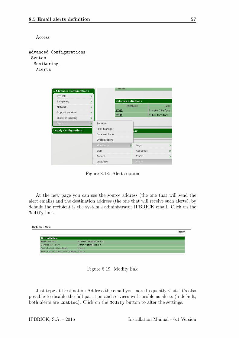
Access:
Advanced Configurations
System
Monitoring
Alerts
Figure 8.18: Alerts option
At the new page you can see the source address (the one that will send thealert emails) and the destination address (the one that will receive such alerts), bydefault the recipient is the system’s administrator IPBRICK email. Click on theModify link.
Figure 8.19: Modify link
Just type at Destination Address the email you more frequently visit. It’s alsopossible to disable the full partition and services with problems alerts (b default,both alerts are Enabled). Click on the Modify button to alter the settings.
IPBRICK, S.A. - 2016 Installation Manual - 6.1 Version
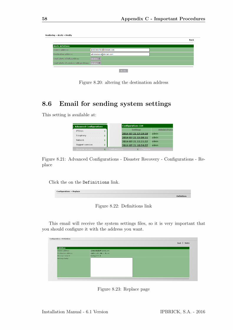
58 Appendix C - Important Procedures
Figure 8.20: altering the destination address
8.6 Email for sending system settings
This setting is available at:
Figure 8.21: Advanced Configurations - Disaster Recovery - Configurations - Re-place
Click the on the Definitions link.
Figure 8.22: Definitions link
This email will receive the system settings files, so it is very important thatyou should configure it with the address you want.
Figure 8.23: Replace page
Installation Manual - 6.1 Version IPBRICK, S.A. - 2016
8.7 Email for sending the databases backups notification 59
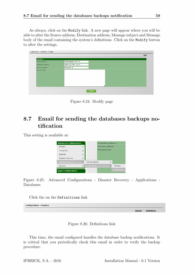
As always, click on the Modify link. A new page will appear where you will beable to alter the Source address, Destination address, Message subject and Messagebody of the email containing the system’s definitions. Click on the Modify buttonto alter the settings.
Figure 8.24: Modify page
8.7 Email for sending the databases backups no-
tification
This setting is available at:
Figure 8.25: Advanced Configurations - Disaster Recovery - Applications -Databases
Click the on the Definitions link.
Figure 8.26: Definitions link
This time, the email configured handles the database backup notifications. Itis critical that you periodically check this email in order to verify the backupprocedure.
IPBRICK, S.A. - 2016 Installation Manual - 6.1 Version
60 Appendix C - Important Procedures
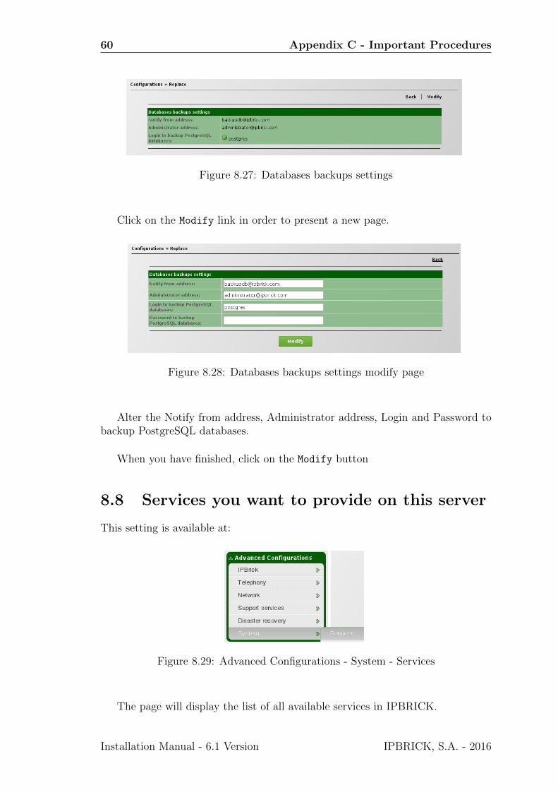
Figure 8.27: Databases backups settings
Click on the Modify link in order to present a new page.
Figure 8.28: Databases backups settings modify page
Alter the Notify from address, Administrator address, Login and Password tobackup PostgreSQL databases.
When you have finished, click on the Modify button
8.8 Services you want to provide on this server
This setting is available at:
Figure 8.29: Advanced Configurations - System - Services
The page will display the list of all available services in IPBRICK.
Installation Manual - 6.1 Version IPBRICK, S.A. - 2016
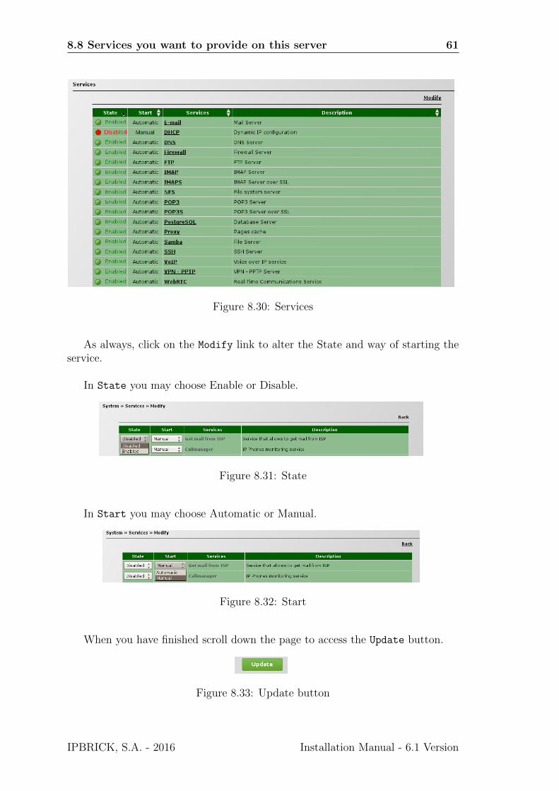
8.8 Services you want to provide on this server 61
Figure 8.30: Services
As always, click on the Modify link to alter the State and way of starting theservice.
In State you may choose Enable or Disable.
Figure 8.31: State
In Start you may choose Automatic or Manual.
Figure 8.32: Start
When you have finished scroll down the page to access the Update button.
Figure 8.33: Update button
IPBRICK, S.A. - 2016 Installation Manual - 6.1 Version