Embed Size (px)
Citation preview
1
IP Traffic EngineeringMuhammad JaseemuddinDept. of Electrical & Computer EngineeringRyerson UniversityToronto, Canada
References1. RFC 32722. Jennifer Rexford et al, Traffic Engineering for ISP Networks3. Juniper, Traffic Engineering with MPLS, APRICOT 20004. P. Ashwood-Smith, B. Jamousi, MPLS Tutorial, Nortel Networks5. A. Leon-Garcia and I. Widjaja, Communication Networks: Fundamental
Concepts and Key Architectures, McGraw Hill, 2004.
2
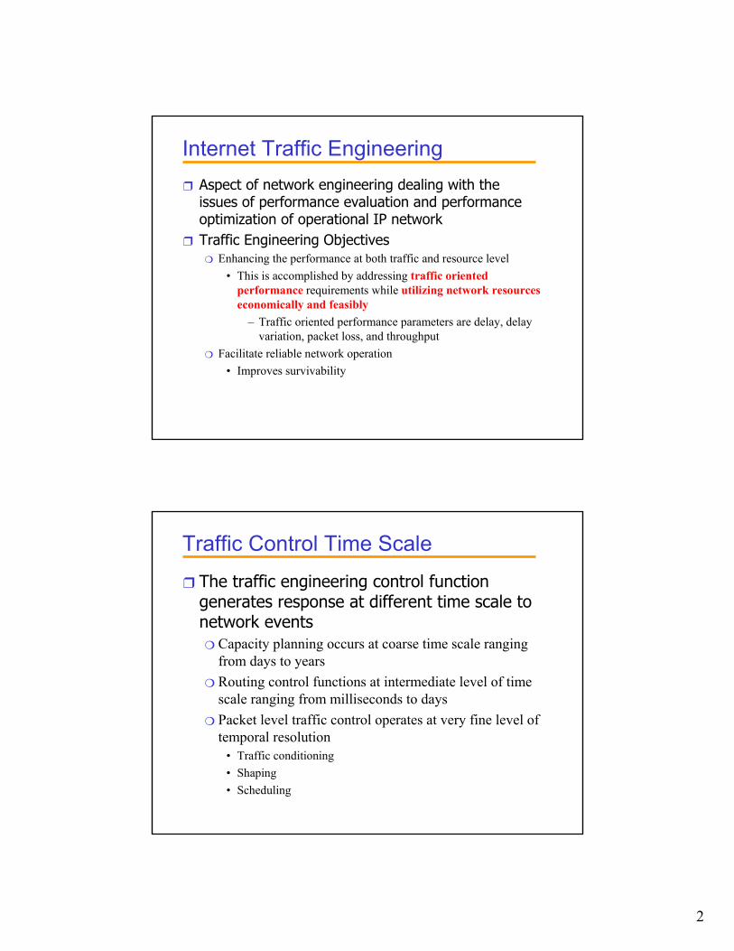
Internet Traffic Engineering❒ Aspect of network engineering dealing with the
issues of performance evaluation and performance optimization of operational IP network
❒ Traffic Engineering Objectives❍ Enhancing the performance at both traffic and resource level
• This is accomplished by addressing traffic oriented performance requirements while utilizing network resources economically and feasibly
– Traffic oriented performance parameters are delay, delay variation, packet loss, and throughput
❍ Facilitate reliable network operation• Improves survivability
Traffic Control Time Scale❒ The traffic engineering control function
generates response at different time scale to network events❍ Capacity planning occurs at coarse time scale ranging
from days to years❍ Routing control functions at intermediate level of time
scale ranging from milliseconds to days❍ Packet level traffic control operates at very fine level of
temporal resolution• Traffic conditioning• Shaping• Scheduling
3
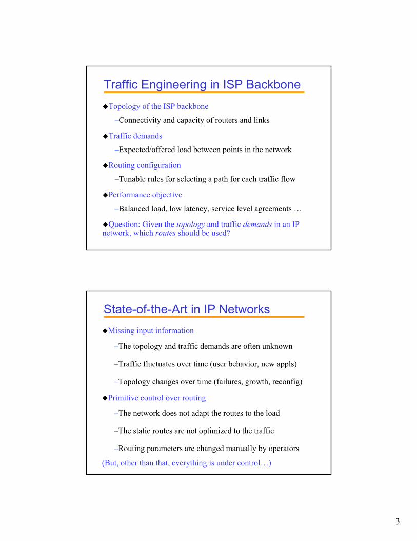
Traffic Engineering in ISP BackboneTopology of the ISP backbone
–Connectivity and capacity of routers and links
Traffic demands
–Expected/offered load between points in the network
Routing configuration
–Tunable rules for selecting a path for each traffic flow
Performance objective
–Balanced load, low latency, service level agreements …
Question: Given the topology and traffic demands in an IP network, which routes should be used?
State-of-the-Art in IP NetworksMissing input information
–The topology and traffic demands are often unknown
–Traffic fluctuates over time (user behavior, new appls)
–Topology changes over time (failures, growth, reconfig)
Primitive control over routing
–The network does not adapt the routes to the load
–The static routes are not optimized to the traffic
–Routing parameters are changed manually by operators
(But, other than that, everything is under control…)
4
Requirements for Traffic EngineeringModels
–Traffic demands
–Network topology/configuration
–Internet routing algorithms
Techniques for populating the models–Measuring/computing the traffic demands
–Determining the network topology/configuration
–Optimizing the routing parameters
Analysis of the traffic demands–Knowing how the demands fluctuates over time
–Understanding the traffic engineering implications
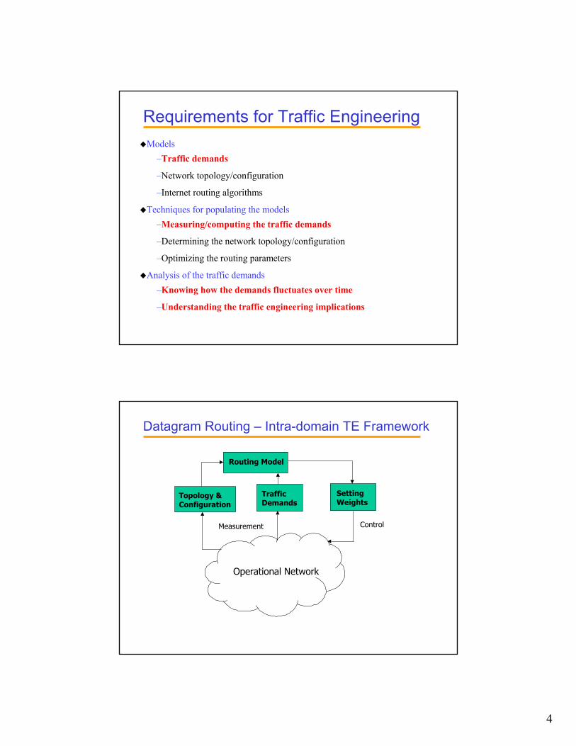
Datagram Routing – Intra-domain TE Framework
Operational Network
Topology & Configuration
Traffic Demands
Setting Weights
Routing Model
Measurement Control
5
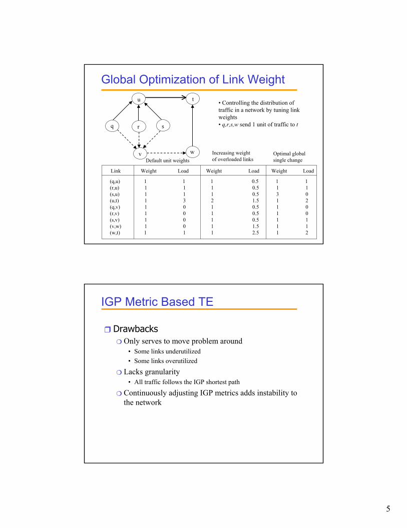
Global Optimization of Link Weightu
v
q r s
t
w
(q,u) 1 1 1 0.5 1 1(r,u) 1 1 1 0.5 1 1(s,u) 1 1 1 0.5 3 0(u,t) 1 3 2 1.5 1 2(q,v) 1 0 1 0.5 1 0(r,v) 1 0 1 0.5 1 0(s,v) 1 0 1 0.5 1 1(v,w) 1 0 1 1.5 1 1(w,t) 1 1 1 2.5 1 2
Link Weight Load Weight Load Weight Load
Default unit weightsIncreasing weight of overloaded links
Optimal global single change
• Controlling the distribution of traffic in a network by tuning link weights• q,r,s,w send 1 unit of traffic to t
IGP Metric Based TE
❒ Drawbacks❍ Only serves to move problem around
• Some links underutilized • Some links overutilized
❍ Lacks granularity• All traffic follows the IGP shortest path
❍ Continuously adjusting IGP metrics adds instability to the network
6
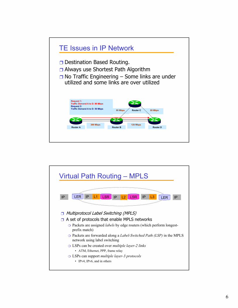
TE Issues in IP Network
❒ Destination Based Routing.❒ Always use Shortest Path Algorithm❒ No Traffic Engineering – Some links are under
utilized and some links are over utilized
Router C 80 Mbps80 Mbps
Router A
Request 1:Traffic Demand A to D: 80 MbpsRequest 2:Traffic Demand A to D: 50 Mbps
300 MbpsRouter B Router D
120 Mbps
Virtual Path Routing – MPLS
IP L1IP L2IP L3IP IPLER LERLSRLSR
❒ Multiprotocol Label Switching (MPLS)❒ A set of protocols that enable MPLS networks
❍ Packets are assigned labels by edge routers (which perform longest-prefix match)
❍ Packets are forwarded along a Label-Switched Path (LSP) in the MPLS network using label switching
❍ LSPs can be created over multiple layer-2 links• ATM, Ethernet, PPP, frame relay
❍ LSPs can support multiple layer-3 protocols• IPv4, IPv6, and in others
7
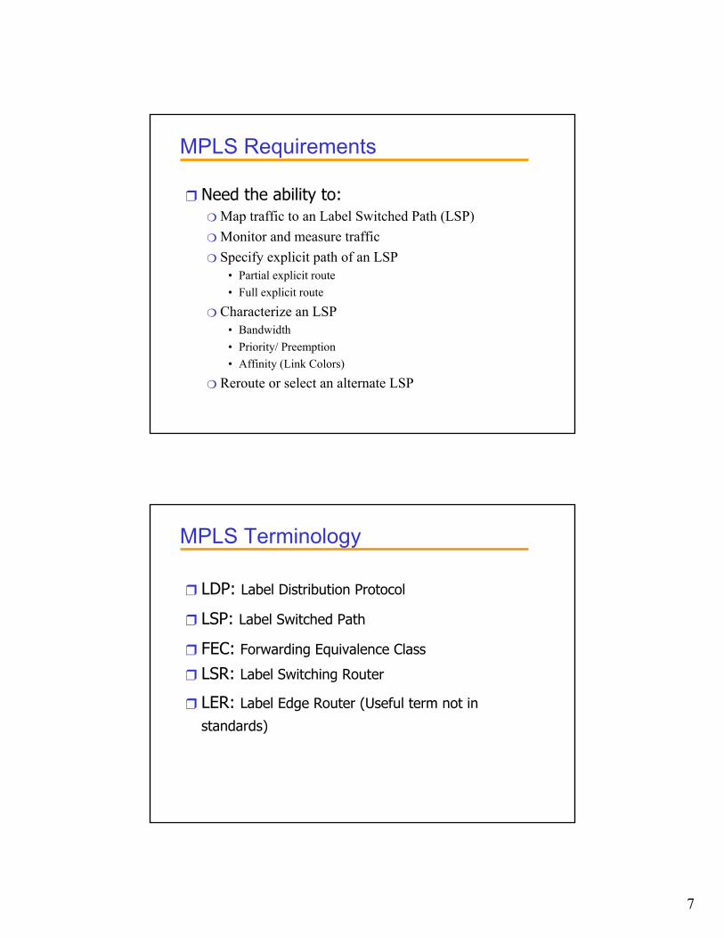
MPLS Requirements
❒ Need the ability to:❍ Map traffic to an Label Switched Path (LSP)❍ Monitor and measure traffic❍ Specify explicit path of an LSP
• Partial explicit route• Full explicit route
❍ Characterize an LSP• Bandwidth• Priority/ Preemption• Affinity (Link Colors)
❍ Reroute or select an alternate LSP
MPLS Terminology
❒ LDP: Label Distribution Protocol
❒ LSP: Label Switched Path
❒ FEC: Forwarding Equivalence Class
❒ LSR: Label Switching Router
❒ LER: Label Edge Router (Useful term not in
standards)
8
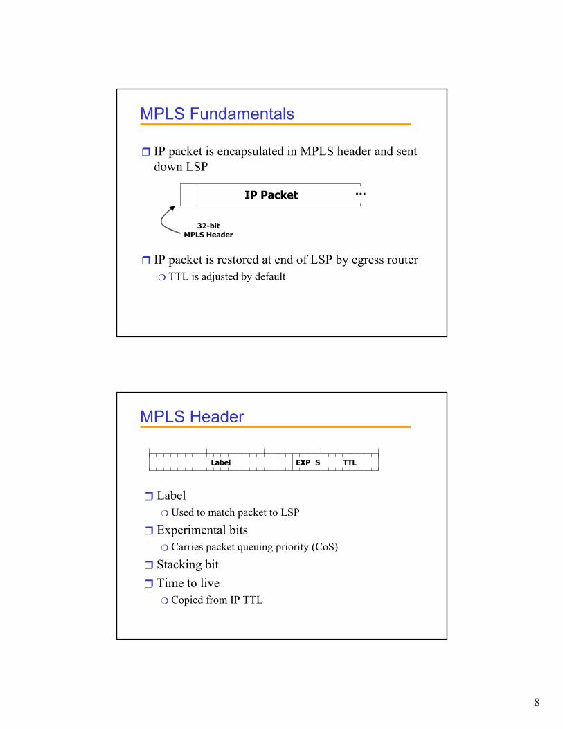
MPLS Fundamentals
❒ IP packet is encapsulated in MPLS header and sent down LSP
❒ IP packet is restored at end of LSP by egress router❍ TTL is adjusted by default
…IP Packet
32-bitMPLS Header
MPLS Header
❒ Label❍ Used to match packet to LSP
❒ Experimental bits❍ Carries packet queuing priority (CoS)
❒ Stacking bit❒ Time to live
❍ Copied from IP TTL
TTLLabel EXP S
9
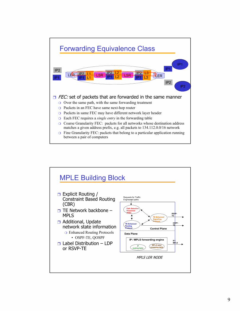
Forwarding Equivalence Class
IP2L1IP2
IP2
LER LERLSRLSRL2IP2 L3IP2
L1IP1 L2IP1 L3IP1IP1
IP1IP1
IP2
❒ FEC: set of packets that are forwarded in the same manner❍ Over the same path, with the same forwarding treatment❍ Packets in an FEC have same next-hop router❍ Packets in same FEC may have different network layer header❍ Each FEC requires a single entry in the forwarding table❍ Coarse Granularity FEC: packets for all networks whose destination address
matches a given address prefix, e.g. all packets to 134.112.0.0/16 network❍ Fine Granularity FEC: packets that belong to a particular application running
between a pair of computers
MPLE Building Block
Path Selection Processor (PSE)
TE Enhanced Routing Protocol
TE Enhanced Signalling Protocol
Control Plane
IP / MPLS forwarding engine
IP routing table
MPLS labelswapping table
Data Plane
Requests for Traffic Engineered paths
RSVP-TE
OSPF-TE
IP / MPLS
MPLS LER NODE
❒ Explicit Routing / Constraint Based Routing (CBR)
❒ TE Network backbone –MPLS
❒ Additional, Update network state information
❍ Enhanced Routing Protocols• OSPF-TE, QOSPF
❒ Label Distribution – LDP or RSVP-TE
10
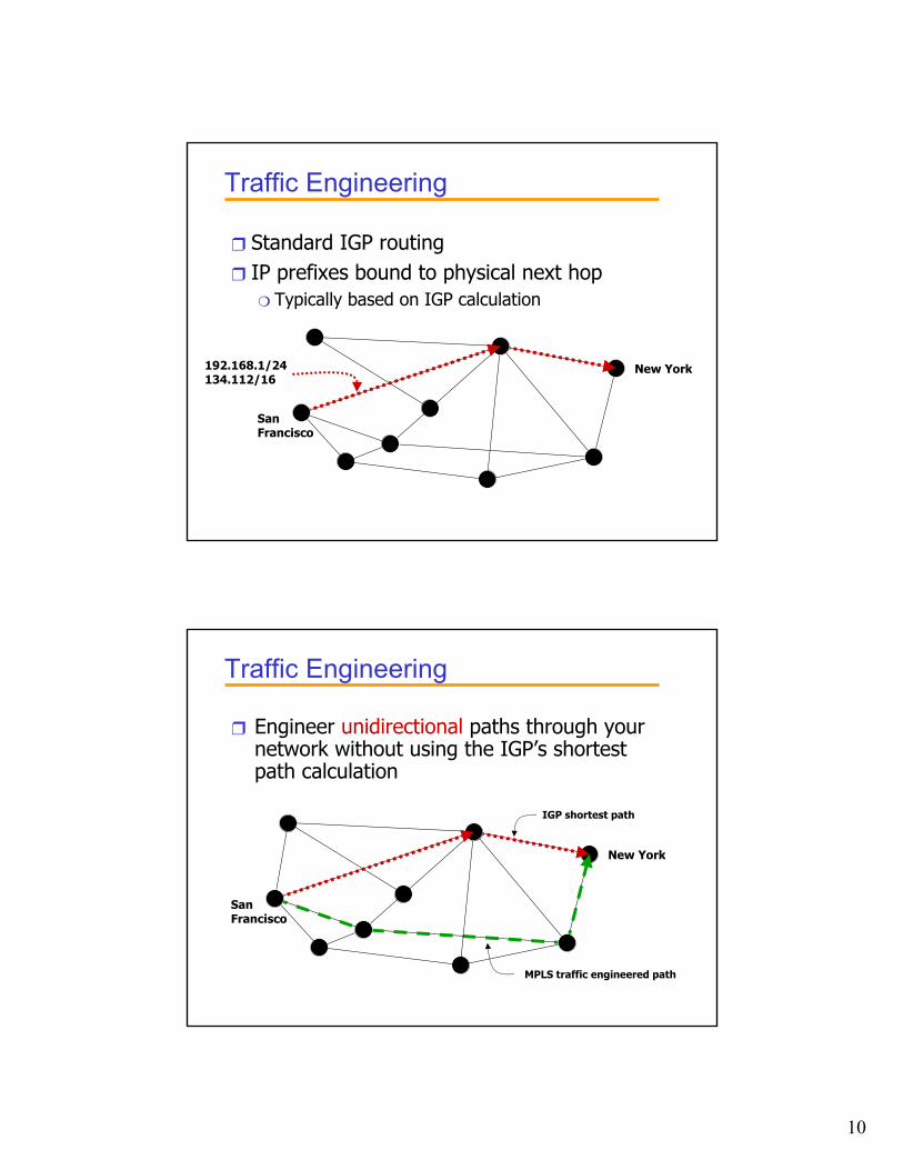
Traffic Engineering
❒ Standard IGP routing❒ IP prefixes bound to physical next hop
❍ Typically based on IGP calculation
SanFrancisco
New York192.168.1/24134.112/16
Traffic Engineering
❒ Engineer unidirectional paths through your network without using the IGP’s shortest path calculation
SanFrancisco
IGP shortest path
MPLS traffic engineered path
New York
11
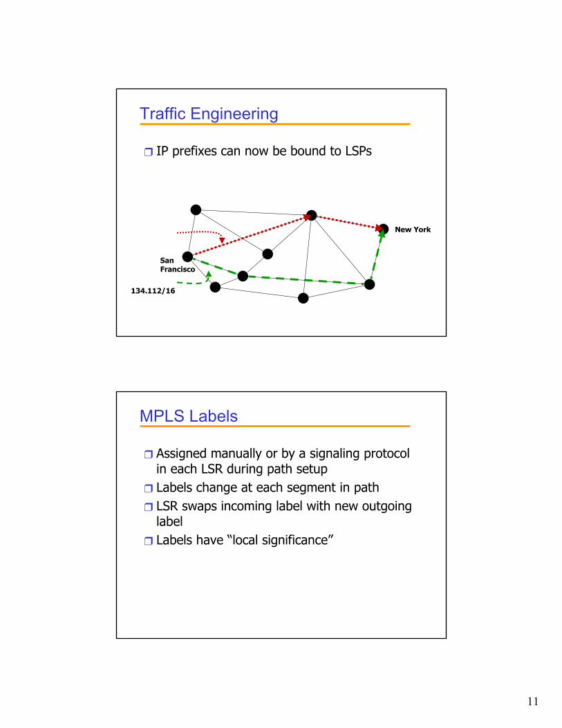
Traffic Engineering
❒ IP prefixes can now be bound to LSPs
SanFrancisco
New York
134.112/16
MPLS Labels
❒ Assigned manually or by a signaling protocol in each LSR during path setup
❒ Labels change at each segment in path❒ LSR swaps incoming label with new outgoing
label ❒ Labels have “local significance”
12
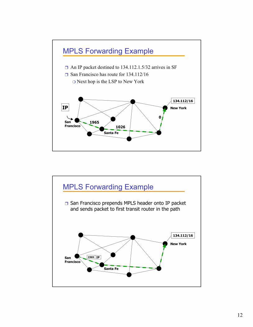
MPLS Forwarding Example
❒ An IP packet destined to 134.112.1.5/32 arrives in SF❒ San Francisco has route for 134.112/16
❍ Next hop is the LSP to New York
SanFrancisco
New YorkIP
Santa Fe
134.112/16
19651026
0
MPLS Forwarding Example
❒ San Francisco prepends MPLS header onto IP packet and sends packet to first transit router in the path
SanFrancisco
New York
Santa Fe
134.112/16
IP1965
13
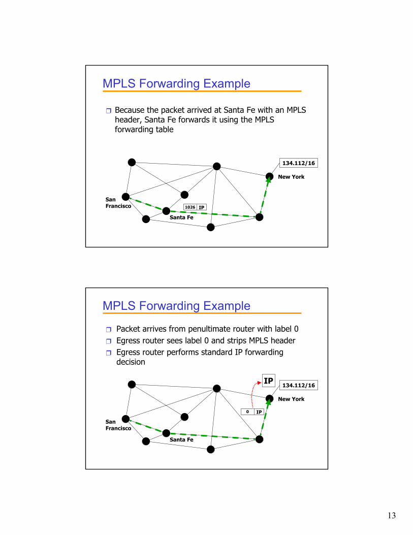
MPLS Forwarding Example
❒ Because the packet arrived at Santa Fe with an MPLS header, Santa Fe forwards it using the MPLS forwarding table
SanFrancisco
New York
Santa Fe
134.112/16
IP1026
MPLS Forwarding Example
❒ Packet arrives from penultimate router with label 0❒ Egress router sees label 0 and strips MPLS header❒ Egress router performs standard IP forwarding
decision
SanFrancisco
New York
Santa Fe
IP134.112/16
IP0
14
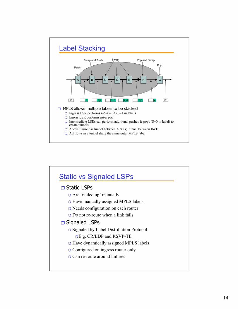
Label Stacking
A B F G
Push
Swap and Push Pop and Swap
Pop
C D E
Swap
3 22 27 26 8 5 4IP IP
❒ MPLS allows multiple labels to be stacked❍ Ingress LSR performs label push (S=1 in label)❍ Egress LSR performs label pop❍ Intermediate LSRs can perform additional pushes & pops (S=0 in label) to
create tunnels ❍ Above figure has tunnel between A & G; tunnel between B&F❍ All flows in a tunnel share the same outer MPLS label
Static vs Signaled LSPs❒ Static LSPs
❍ Are ‘nailed up’ manually❍ Have manually assigned MPLS labels❍ Needs configuration on each router❍ Do not re-route when a link fails
❒ Signaled LSPs❍ Signaled by Label Distribution Protocol
❍ E.g. CR/LDP and RSVP-TE❍ Have dynamically assigned MPLS labels❍ Configured on ingress router only❍ Can re-route around failures
15
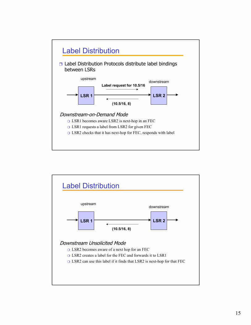
Label Distribution❒ Label Distribution Protocols distribute label bindings
between LSRs
LSR 1 LSR 2
Label request for 10.5/16
(10.5/16, 8)
upstreamdownstream
Downstream-on-Demand Mode❍ LSR1 becomes aware LSR2 is next-hop in an FEC❍ LSR1 requests a label from LSR2 for given FEC❍ LSR2 checks that it has next-hop for FEC, responds with label
Label Distribution
LSR 1 LSR 2
(10.5/16, 8)
upstreamdownstream
Downstream Unsolicited Mode❍ LSR2 becomes aware of a next hop for an FEC❍ LSR2 creates a label for the FEC and forwards it to LSR1❍ LSR2 can use this label if it finds that LSR2 is next-hop for that FEC
16
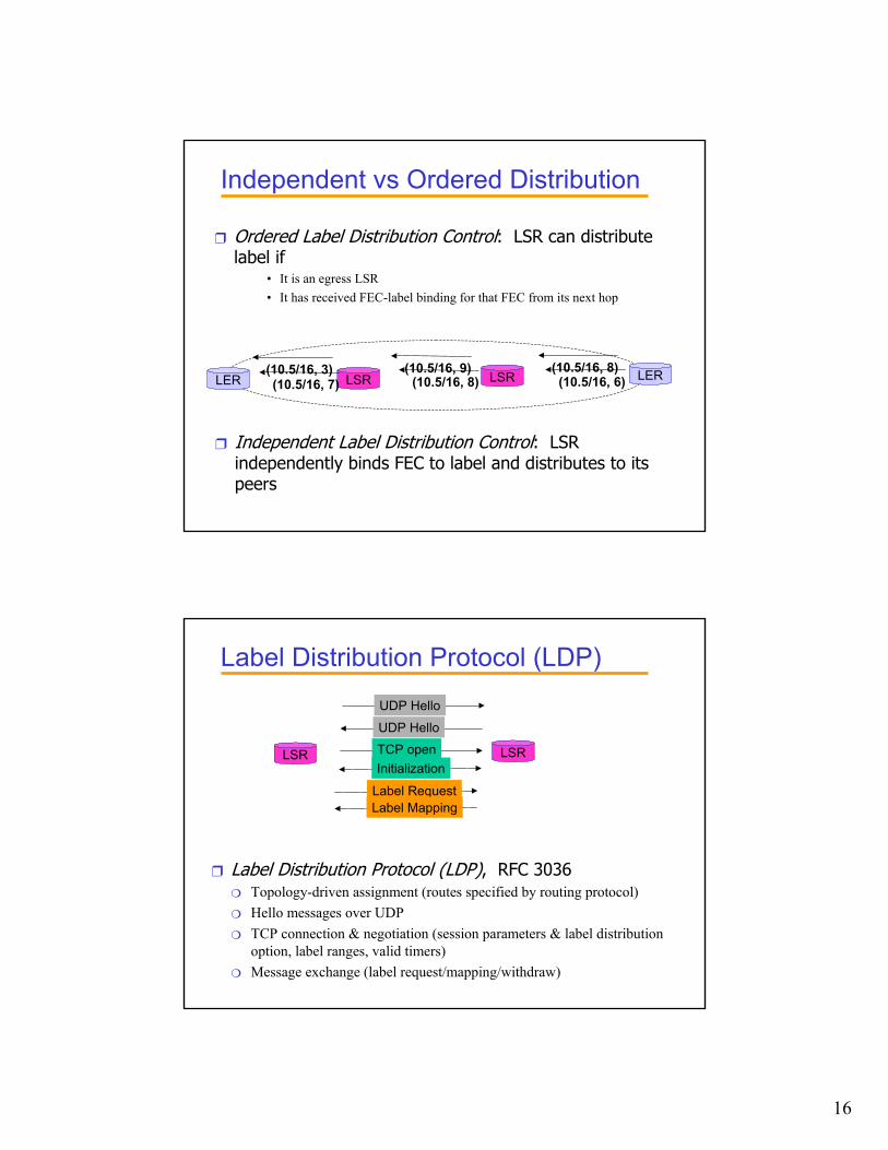
Independent vs Ordered Distribution
❒ Ordered Label Distribution Control: LSR can distribute label if
• It is an egress LSR• It has received FEC-label binding for that FEC from its next hop
LER LERLSRLSR(10.5/16, 8)(10.5/16, 9)(10.5/16, 3)(10.5/16, 6)(10.5/16, 8)(10.5/16, 7)
❒ Independent Label Distribution Control: LSR independently binds FEC to label and distributes to its peers
Label Distribution Protocol (LDP)
LSR LSR
UDP HelloUDP Hello
InitializationTCP open
Label RequestLabel Mapping
❒ Label Distribution Protocol (LDP), RFC 3036❍ Topology-driven assignment (routes specified by routing protocol)❍ Hello messages over UDP❍ TCP connection & negotiation (session parameters & label distribution
option, label ranges, valid timers)❍ Message exchange (label request/mapping/withdraw)
17
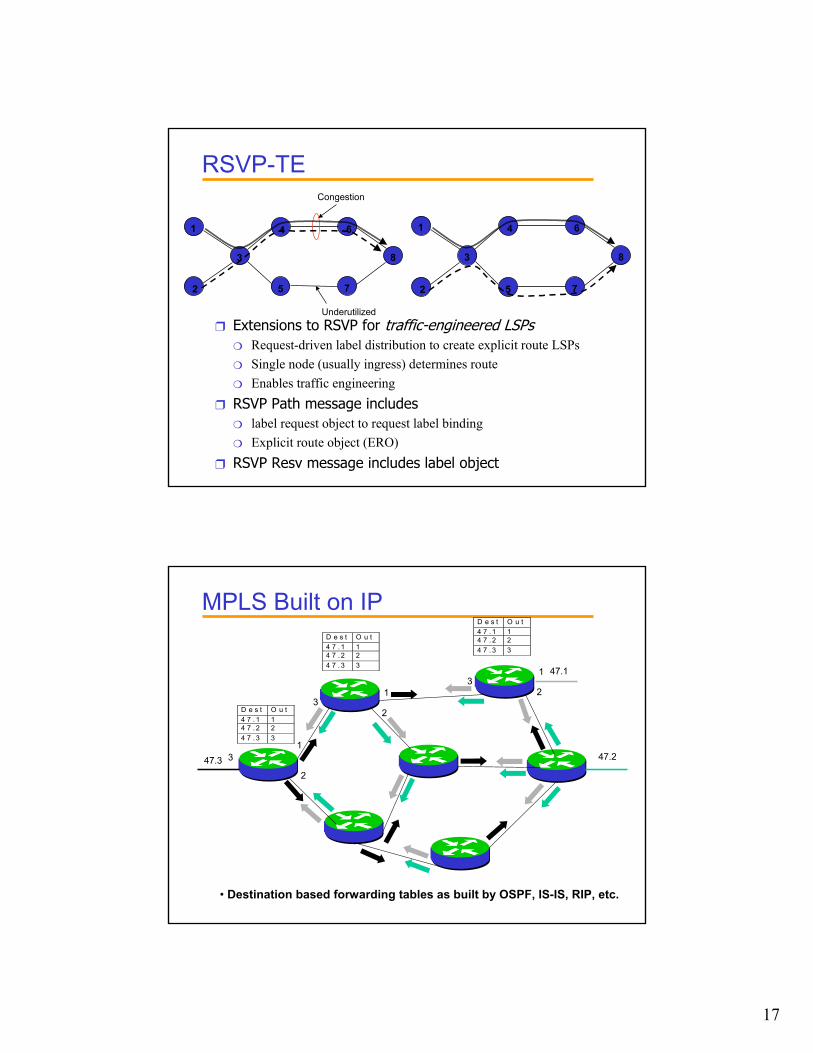
RSVP-TE
3
64
8
1
2 5 7
Congestion
Underutilized
3
64
8
1
2 5 7
❒ Extensions to RSVP for traffic-engineered LSPs❍ Request-driven label distribution to create explicit route LSPs❍ Single node (usually ingress) determines route❍ Enables traffic engineering
❒ RSVP Path message includes❍ label request object to request label binding❍ Explicit route object (ERO)
❒ RSVP Resv message includes label object
MPLS Built on IP
47.1
47.247.3
D e s t O u t4 7 . 1 14 7 . 2 24 7 . 3 3
1
23
D e s t O u t4 7 . 1 14 7 . 2 24 7 . 3 3
D e s t O u t4 7 . 1 14 7 . 2 24 7 . 3 3
1
23
1
2
3
• Destination based forwarding tables as built by OSPF, IS-IS, RIP, etc.
18
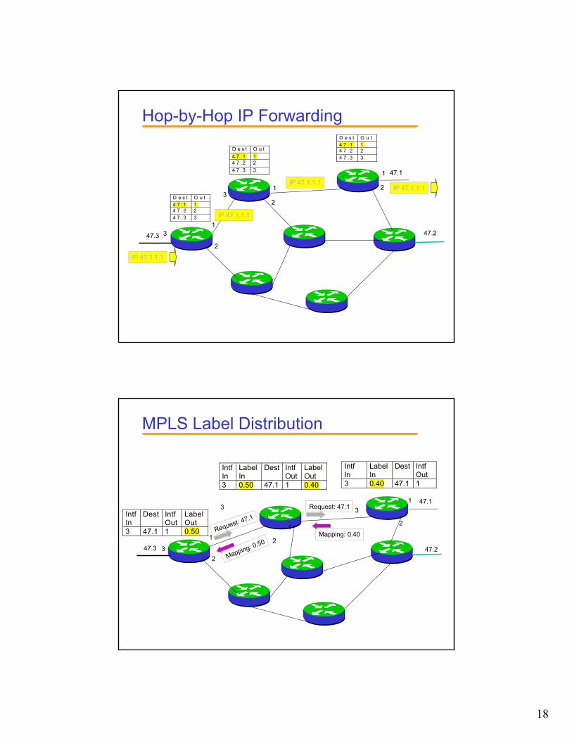
Hop-by-Hop IP Forwarding
47.1
47.247.3
IP 47.1.1.1
D e s t O u t4 7 .1 14 7 .2 24 7 .3 3
1
23
D e s t O u t4 7 . 1 14 7 . 2 24 7 . 3 3
1
2
1
2
3
IP 47.1.1.1
IP 47.1.1.1IP 47.1.1.1
D e s t O u t4 7 . 1 14 7 . 2 24 7 . 3 3
MPLS Label Distribution
IntfIn
LabelIn
Dest IntfOut
3 0.40 47.1 1
IntfIn
LabelIn
Dest IntfOut
LabelOut
3 0.50 47.1 1 0.40
47.1
47.247.3
1
2
31
2
1
23
3IntfIn
Dest IntfOut
LabelOut
3 47.1 1 0.50 Mapping: 0.40
Request: 47.1
Mapping: 0.50
Request: 47.1
19
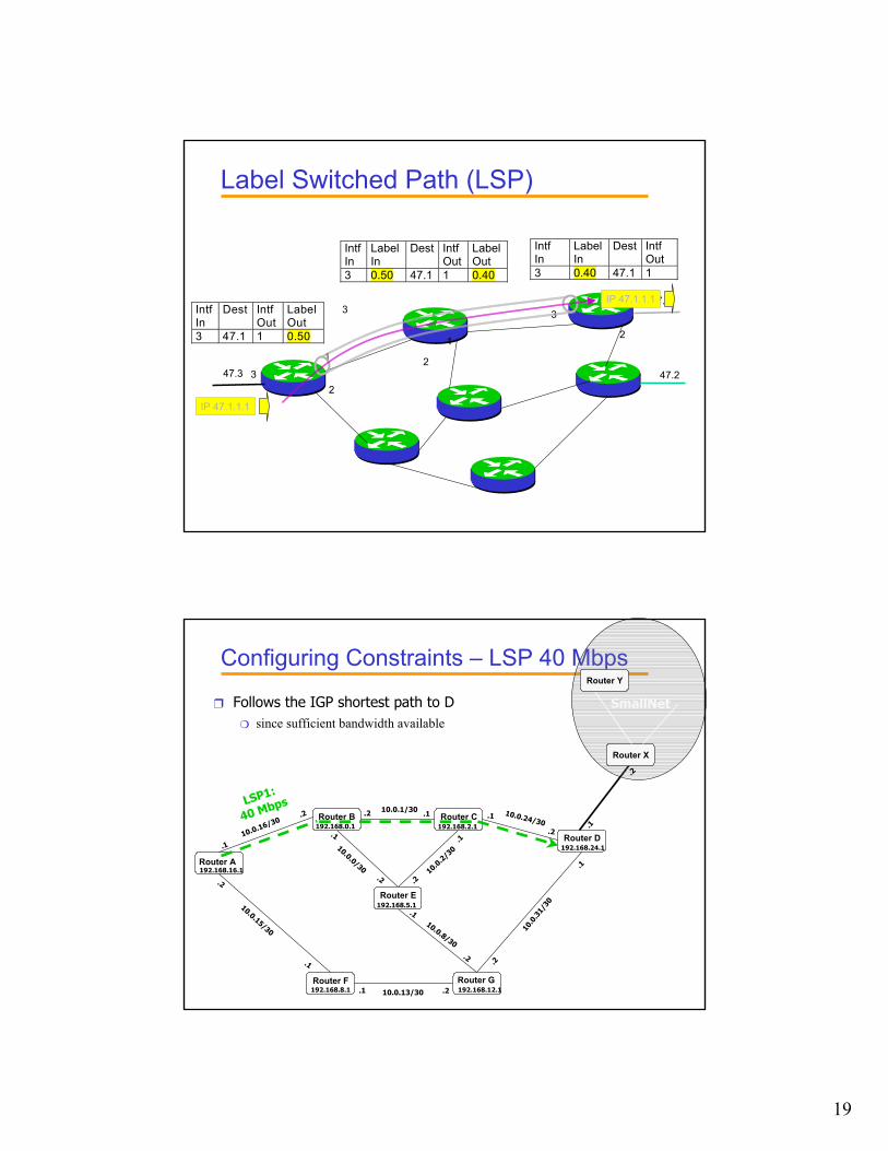
Label Switched Path (LSP)
IntfIn
LabelIn
Dest IntfOut
3 0.40 47.1 1
IntfIn
LabelIn
Dest IntfOut
LabelOut
3 0.50 47.1 1 0.40
47.1
47.247.3
1
2
31
2
1
23
3IntfIn
Dest IntfOut
LabelOut
3 47.1 1 0.50
IP 47.1.1.1
IP 47.1.1.1
Configuring Constraints – LSP 40 Mbps
Router X
SmallNet
Router Y
.2
Router B Router C
Router E
Router D
.2
.1
.2.1
10.0
.31/
30
Router GRouter F
192.168.16.1
192.168.0.1 192.168.2.1
192.168.5.1
192.168.8.1 192.168.12.1
192.168.24.1
Router A .1
.2
10.0.13/30
10.0.0/30
10.0.24/30.1
.2
10.0.1/30 .1.2
10.0.8/30
.1
.210.0
.2/3
0.1
.2
10.0.16/30.2
.1
10.0.15/30
.2
.1
.1
LSP1:
40 Mbps
❒ Follows the IGP shortest path to D ❍ since sufficient bandwidth available
20
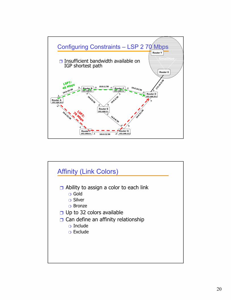
Configuring Constraints – LSP 2 70 Mbps
❒ Insufficient bandwidth available on IGP shortest path
Router X
SmallNet
Router Y
172.
16.4
/30
Router B Router C
Router E
Router D
.2
.1
.2.110
.0.3
1/30
Router GRouter F
192.168.16.1
192.168.0.1 192.168.2.1
192.168.5.1
192.168.8.1 192.168.12.1
192.168.24.1
Router A .1
.2
10.0.13/30
10.0.0/30
10.0.24/30.1
.2
10.0.1/30 .1.2
10.0.8/30
.1
.210.0
.2/3
0.1
.2
10.0.16/30.2
.1
10.0.15/30
.2
.1
.1
LSP2: 70 Mbps
LSP1:
40 Mbps
Affinity (Link Colors)
❒ Ability to assign a color to each link❍ Gold❍ Silver❍ Bronze
❒ Up to 32 colors available❒ Can define an affinity relationship
❍ Include❍ Exclude
21
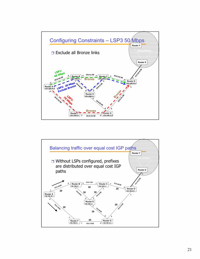
Configuring Constraints – LSP3 50 Mbps
Router B Router C
Router E
Router D
.2
.1
.2.110
.0.3
1/30
Router GRouter F
192.168.16.1
192.168.0.1 192.168.2.1
192.168.5.1
192.168.8.1 192.168.12.1
192.168.24.1
Router A .1
.2
10.0.13/30
10.0.0/30
10.0.24/30.1
.2
10.0.1/30 .1.2
10.0.8/30
.1
.210.0
.2/3
0.1
.2
10.0.16/30.2
.1
10.0.15/30
.2
.1
Router X
SmallNet
Router Y
172.
16.4
/30
.1
LSP1:
40 Mbps
LSP2: 70 Mbps
Bronze
Bronz
e
Bronze
LSP3: 20 Mbps
Exclude Bronze
❒ Exclude all Bronze links
Router B Router C
Router E
Router D
.2
.1
.2.1
10.0.
31/30
Router GRouter F
192.168.16.1
192.168.0.1 192.168.2.1
192.168.5.1
192.168.8.1 192.168.12.1
192.168.24.1
Router A .1
.2
10.0.13/30
10.0.0/30
10.0.24/30.1
.2
10.0.1/30 .1.2
10.0.8/30
.1
.210
.0.2/3
0
.1
.2
10.0.16/30.2
.1
10.0.15/30
.2
.1
Router X
SmallNet
Router Y
172.1
6.4/30
.2
.12020
20
20
20
20
3030
30
❒ Without LSPs configured, prefixes are distributed over equal cost IGP paths
Balancing traffic over equal cost IGP paths
22
Router B Router C
Router E
Router D
.2
.1
.2.110
.0.3
1/30
Router GRouter F
192.168.16.1
192.168.0.1 192.168.2.1
192.168.5.1
192.168.8.1 192.168.12.1
192.168.24.1
Router A .1
.2
10.0.13/30
10.0.0/30
10.0.24/30.1
.2
10.0.1/30 .1.2
10.0.8/30
.1
.210.0
.2/3
0.1
.2
10.0.16/30.2
.1
10.0.15/30
.2
.1
Router X
SmallNet
Router Y
172.
16.4
/30
.2
.12020
20
20
20
20
3030
30
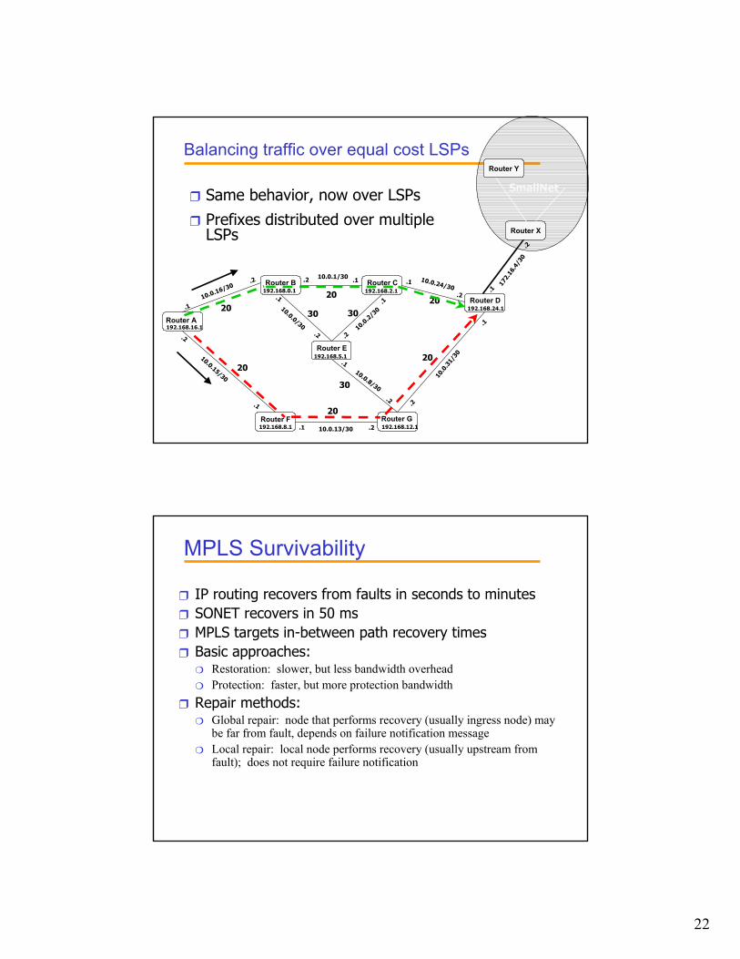
❒ Same behavior, now over LSPs
❒ Prefixes distributed over multiple LSPs
Balancing traffic over equal cost LSPs
MPLS Survivability
❒ IP routing recovers from faults in seconds to minutes❒ SONET recovers in 50 ms❒ MPLS targets in-between path recovery times❒ Basic approaches:
❍ Restoration: slower, but less bandwidth overhead❍ Protection: faster, but more protection bandwidth
❒ Repair methods:❍ Global repair: node that performs recovery (usually ingress node) may
be far from fault, depends on failure notification message❍ Local repair: local node performs recovery (usually upstream from
fault); does not require failure notification
23
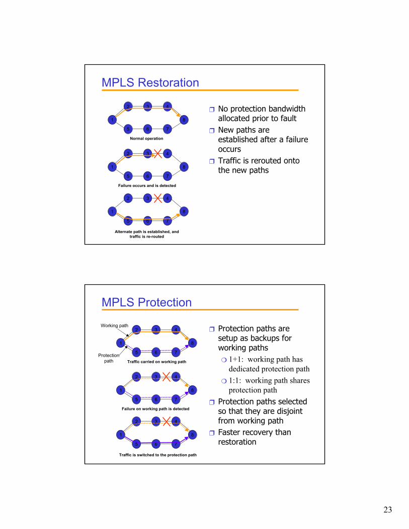
MPLS Restoration
Normal operation
1
2 43
8
5 76
1
2 43
8
5 76
1
2 43
8
5 76
Failure occurs and is detected
Alternate path is established, andtraffic is re-routed
❒ No protection bandwidth allocated prior to fault
❒ New paths are established after a failure occurs
❒ Traffic is rerouted onto the new paths
MPLS Protection
Traffic carried on working path
1
2 43
8
5 76
1
2 43
8
5 76
1
2 43
8
5 76
Failure on working path is detected
Traffic is switched to the protection path
Working path
Protectionpath
❒ Protection paths are setup as backups for working paths❍ 1+1: working path has
dedicated protection path❍ 1:1: working path shares
protection path❒ Protection paths selected
so that they are disjoint from working path
❒ Faster recovery than restoration