Embed Size (px)
Citation preview

IP O PEO HEAD UP DISPLAY TT 01EVALUATION OF HERD-U (U) CREW SYSTENS CONSULTANTSYELLOW SPRINGS ON R L NEWMNAN SEP 87
UNCLASSIFIED AFWAL-TR-87-3855-VOL-3 F33615-85-C-3602 F/G 1/4 NL'oIIIII
IIIIIIIIIIIIIIEEIIIIIIIIIIE
-U -

' 111 10-0i 11120
111111.8
IIJI25 1114 1116

O FILE COPY
AFWAL-TR-87-3055Volume III
IMPROVEMENT OF HEAD-UP DISPLAY STANDARDS
Volume III: An Evaluation of Head-Up Display Safety
00* Richard L. Newman
Crew Systems Consultants
U PO Box 481Yellow Springs, OH 45387 D T IC
ELECTE
September 1987 S I 1
DFinal Report for Period Oct 84 - June 87
Approed for public release; distribution unlimited.
FLIGHT DYNAMICS LABORATORYAIR FORCE WRIGHT AERONAUTICAL LABORATORIES
AIR FORCE SYSTEMS COMMANDWRIGHT-PATTERSON AIR FORCE BASE, OHIO 45433-6553
,20

NOTICE
When Government drawings, specifications, or other data are used fnr anypurpose other than in connection with a definitely Government-relatedprocurement, the United States Government incurs no responsibility or anyobligation whatsoever. The fact that the Government may have formulated or inany way supplied the said drawings, specifications, or other data, is not tobe regarded by implication, or otherwise in any manner construed, as licersingthe holder, or any other person or corporation; or as conveying any rights orpermission to manufacture, use, or sell any patented invention that may in anyway be related thereto.
This report has been reviewed by the Office of Public Affairs (ASD/PA)and is releasable to the National Technical Information Service (NTIS). AtNTIS, it will be available to the general public, including foreign nations.
This technical report has been reviewed and is approved for publication.
William L. Augustine Ronald I. Morishige, Col, USAF
Electronics Engineer Chief, Crew Systems Development BranchInformation Interface Group
FOP THE COMt- ANDER
EUGFPE A. SMITH, Lt Col, USAFChief, Flight Control DivisionFlight Dynamics Laboratory
If your address has changed, if you wish to be removed from our mailing%P, list, or if the addressee is no longer employed by your organization please
notify AFWAL/FIGRB , Wright-Patterson AFB, OH 45433- 6553 to help us maintaina current mailing list.
. Copies of this report should not be returned unless return is required bysecurity corsiderations, contractual obligations, or notice on a specificdocument.-.>?

REPORT DOCUMENTATION PAGE~ 4~'JP ~ .ut4if Y I IA341IIIAI IN III I"I-IrHII. 1111 MAI4KINI".
UNCLASS IFIED:1 NONE*E, 5,RiY CLASSIFICATION ^AUTHORITY 3 OiSTRIBUTIONIAVAILABILITY OF REPORT
Approved for Public Release;2b DECLASSiFICATIONDOWNGRADING SCHEDULE Distribution Unlimited
'nFERPORMING ORGANIZATION REPORT NUMBERISl S. MONITORING ORGANIZATION REPORT NUMBER(S)
AFWAL-TR-87-3055, Vol IIITR-87--16 ________ _________________________
N& AME OF PERFORMING ORGANIZATION 6b. OFFICE SYMBOL 7s. NAME OF MONITORING ORGANIZATION
r pilt le Flight [Dynamics Laboratory (AFWAL/FLCRB)
Crew Systems Consultants ________ AF Wright Aeronautical Laboratories6c. ADDRESS 'City. State .und I~IP Code) 7 b. ADDRESS #City. State an~d ZIP Code)
PO Box 481 Wright-Patterson AFB, OH 45433-6553Yellow Springs, OH 45387
So. NAME OF FUNDING,SPONSORING 8b. OFFICE SYMBOL 9. PROCUREMENT INSTRUMENT IDENTIFICATION NUMBER
ORGANIZATION Ofappiecabie I 58-C3
dc ACDORI 11.I , 10~i .u' i %..Ii0)jUNCrE OF FIJNLINI, NOISWrltgtlt-L'jct I.r,,i4I AF11. 0 11 *','4 1 1)1 PROGRAM PROjFCT TASK WORKC UNI1T
ELEMENT NO NO NO NO
1 I. Ti TLE Inctude Security Claaaaficationl 65502F 3005 30 21An Evaluation of Head-Up Display Safety ______
12. PERSONAL AUTHOR(S)
Richard L. Newman13& TYPE OF REPORT 13b. TIME COVERED 14. DATE OF REPORT , Yr., Mo., Day) 15. PAGE COUNT
FinalFROM 841001_ TO_ 8706151 Sept 87 3
17. ABSTRA CTDE 18.~n on~EC TERMS (Cntnu an~ur revrs Ifntf neeyar andl idntfybybocvrlb
1A review of tilt! Sdlety aSPeCt8i of head-up dispLaiys (H-UI~s) is presented. BecduSe of thewidespread concern about the use of HUDs during unusual attitudes, particular attentionwas paid to spatial disorientation and the implications of flying by reference to the HUDduring unusual attitude recoveries. It is concluded that the HUD is not inherently unsafeduring instrument meterological conditions and is quite suitable for use as a primary flighdisplay. It is clear, however, that current military training for pilots in the use of theHUD is inadequate both in terms of initial pilot training and recurrent training. Anyproblem with head-up displays is exacerbated by the lack of adequate training. The use ofa generic HUD procedures trainer is highly recommended.ji 1,O
20. DISTRIBUTION/AVAILABI1LITY OF ABSTRA97T 21. ABSTRACT SECURITY CLASSIFICATION
UNCLASSIFIED/UNLIMITED ( SAME AS RPT. nOTIC USERS 0 UNCLASSIFIED
22s. NAME OF RESPONSIBLE INDIVIDUAL 22b. TELEPHONE NUMBER 22c. OFFICE SYMBO0L(include Area Ciode)
William Augustine (513) 255-8272 AFWAL/FIGRB
-- 1
Summxa ry
A review of the safety aspects of head-up displays (HUDs) ispresented. Because of the widespread concern about the use ofHUDs during unusual attitudes, particular attention was paid tospatial disorientation and the implications of flying byreference to the HUD during unusual attitude recoveries. It isconcluded that the HUD is not inherently unsafe during instrumentmeterological conditions and is quite suitable for use as aprimary flight display. It is clear, however, that currentmilitary training for pilots in the use of the HUD is inadequateboth in terms of initial pilot training and recurrent training.Any problem with head-up displays is exacerbated by the lack ofadequate training. The use of a generic HUD procedures traineris highly recommended.
Acknowledgements
This study was part of a project to develop criteria forhead-up displays (HUDs). The study was performed under contractF33615-85-C-3602 and sponsored by the Flight Dynamics Laboratory,Aeronautical Systems Division (AFSC), Wright-Patterson AFB. Mr.William Augustine served as Government Project Engineer.
Several individuals assisted in the development of this re-port by offering helpful comments, suggestions, and acting assounding boards for ideas. In particular, we wish to thankMajors Gary Griffith, Hal Hart, and Rick Kleinhanst of the AirForce Instrument Flight Center; Mr. Fred Hoerner of the NavalAir Test Center; Captain Tom Foxworth of United Air Lines; Cap-tain Phil Vollelunga, a USAF exchange officer with the CanadianInstrument Check Pilot School; and Mr. Hans Galli of Pilatus Air-craft. Their contributions are gratefully acknowledg d.
0 L,.0i+ + +4i ........OTtO 4V
8PETOV. _
t iD s t -
44

0
*s
*1~*
9..
0
k
SW
p
"I
0
.1
0

Table of Contents
Summary...................................................i
Acknowledgements............................................11i
Table of Contents ..... 6........................ iii
List of Tables and Figures............................... iv'
List of Abbreviations.................................. iv
I. INTrRODUCTION..........................................1IA. HistLorical Review
*B. Air Force StudiesC. HUD Safety
II. THE HUD VERSUS "REAL" INSTRUMENTS ................. 4A. ComparisonB. Velocity Vector ConsiderationsC. Aircraft and Mission Characteristics
III. THE HUD IN SPATIAL DISORIENTATION ................. 11-'A. Background
B. Spatial DisorientationC. Loss of Situational AwarenessD. Effect of The HUDE. HUD Syinbologies for Enhanced Unusual
Attitude Recovery
IV. TRAINING ISSUES...................................... 21*A. Current Training*B. HUD training
C. When to Introduce the HUDD. The HUD in Basic TrainingE. The HUD Procedures Trainer
V. CONCLUSIONS......................... o . . .. o. ... .o. 26
VII. REFERENCES.......... .o . ... .. ... o - .. . .. . . . .. -.. %.. 27
6
6z

-iv-
List of Table and Figures
Table I Display Characteristics .......................... 9Figure 1 Klopfstein HUD Format ......................... 10
List of Abbreviations
ADI Attitude director indicatorAFB Air Force BaseAFIFC Air Force Instrument Flight CenterAFM Air Force ManualAFWAL Air Force Wright Aeronautical Laboratories
* AGARD Advisory Group for Aeronautical Research andaDevelopment
ALPA Air Line Pilots AssociationCCIL Continuously computed impact lineCFIT Controlled flight into terrainCRT Cathode ray tubeEADI Electronic attitude director indicatorFDI Flight Dynamics, Inc.FOV Field-of-viewGPWS Ground proximity warning systemHD Head downICAO International Civil Aviation OrganizationIFC Instrument Flight CenterIFR Instrument flight rulesIMC Instrument meteorological conditionsINS Inertial navigation systemIPIS Instrument Pilot Instructor SchoolHUD Head-up displayLCOS Lead compensating optical sightLIT Lead in trainingLOSA Loss of situational awarenessNADC Naval Air Development CenterNTSB National Transportation Safety BoardPK Probability of killPVD Peripheral vision displayRAE Royal Aircraft EstablishmentRAF Royal Air ForceSDO Spatial disorientationTAC Tactical Air CommantUA Unusual attitudeUPT Undergraduate pilot training
0I
I. INTRODUCTION
The designers of aircraft are rapidly adopting glass cockpittechnology where conventional electromechanical and pneumatic in-struments are being replaced by cathode ray tubes (CRTs) for pre-sentation of information to the pilot and other crew members. InAddition, head-up displays (HUD) are being adopted as the primaryflight reference for instrument meteorological conditions. Thistechnology influx has created the potential for new and uniqueformats by which information critical to flight and mission suc-cess is conveyed to the flight crew.
A. HISTORICAL REVIEW
The HUD is an outgrowth of the reflective gunsight of WorldWar II. In such gunsights, the aiming symbol was generated as acollimated beam of light, projected upwards, and reflected toward
N the pilot by a semi-transparent mirror placed in his field-of-view (FOV) through the windshield. If the design is correct, thepilot will see the symbols floating in his view of the outsidescene. The image of the symbols can be focused to form a virtualimage which appears to lie in the same plane as the outside visu-al scene. From lead-computing gunsights, the next step was to
"-, place flight information in the virtual image.
The reasons for providing a head-up display are seemingly.4 intuitive:
0 A head-up display can reduce pilot workload whenthe piloting task requires head-up, outside-the-
* cockpit flight references.
Improvements in accuracy and efficiency occur fromthe overlay of HUD-presented data with the exter-nal visual scene.
A conformal display will allow the pilot to di-rectly assess the aircraft performance.
Much of the early development of HUDs took place at the UK'sRoyal Aircraft Establishment (RAE) in the late 1950s and early60s. These early studies indicated that a HUD need not be con-formal to the real world, but rather only an approximate overly-ing of symbols and real world cues was required(l-4). Part ofthis may have been the result of a lack of technology to reliablygenerate a conformal contact analog (i. e. no inertial navigationsystems, INSs)
J0 Jl

.• :: - - u- p7 . : . .. n :, ; .,-t trw , . -- 2 r.., - .. -w °,r. , - L: . r i ,.1r xw 'x ,-rrw- rr uw .,- Ur - U
2
The early work at the RAE was based on extensive flight testand simulator experiments. Most of the conclusions were based ona performance metric, that is, the success criteria for a displaywas based on the minimum tracking error. The ability of the pi-lot to monitor the display and his own performance was also notusually considered. Naish, in one simulatoi study, did purposelymisguide the subject pilots to a touchdown off the runway(5). Hefound that the subject pilots tended to ignore the HUD and fly bythe real world cues as they became available. Similar experi-ments were carried out by NASA in the 1970s with similar conclu-sions(6).
At the present time, HUDs are in operational use on mostfighter/attack airplanes. While these HUDs were placed on theseairplanes to serve as gunsights or bombsights, pilots have foundthat they are extremely useful in routine flight. USAF pilotsflying A-7D, F-15, and F-16 fighter aircraft report that they usethe HUD as an important part of their instrument scan (7). TheNavy recognizes the HUD as the primary flight reference for boththe A-7E and F-18. In fact, the HUD symbology is the only sourceof attitude information in the F-18 during instrument flight(other than the standby indicator)
B. AIR FORCE STUDIES
In the mid-1970s, Tactical Air Command (TAC) requested guid-ance on the use of HUDs from the Air Force Instrument Flight Cen-ter (AFIFC,IFC). In the resulting study, IFC found that whilethe HUD did represent a significant aid as a flight reference,the lack of adequate failure detection; an increased tendency to-ward spatial disorientation; and inadequate standardization lim-ited HUDs usefulness as a primary flight reference (8)
A later survey attempted to further define some of the prob-lem areas noted in the IFC survey. This study (7) concluded thatthere appeared to be a dichotomy between useful HUDs and thoseHUDs which were not useful as a primary flight display. Based onpilot comments, a number of issues were raised:
0 The dynamic response of the HUD symbols appeared
to be inadequately controlled by the specifica-* tions. (Most HUD specifications do not address
the dynamic response of the symbols at all.)
. There is a considerable lack of standardizationfrom HUD to HUD in terms of symbology, nomencla-
Mill ture, and operational use.
. Many HUDs had inadequate field-if-view (FOV).
* Most HUDs had inadequate capability to dim thedisplay during night operations.
Nol

3
. There appeared to be a tendency of pilots to re-port spatial disorientation when flying by refer-ence to the HUD.
Since the publication of this survey, some of these issueshave been addressed. The inadequate FOV issue has apparentlybeen dealt with satisfactorily with the advent of diffractionHUDs, although there will probably always be requests from pilotsfor more FOV. One pilot intereviewed in the survey said, "Thereis no such thing as too much field-of-view."
The current HUD program was intended to develop new, stan-dardized HUD criteria. As part of this effort, it has developeda design guide to assist the designer of HUDs in ensuring thatthe next generation HUD will be suitable for the task (9). Thedesign guide also develops guidelines for HUDs intended for useas the primary flight display during instrument meteorologicalconditions (IMC). Other areas of the current program have ad-dressed the other issues: HUD display dynamics (10); HUD accuracyrequirements (11); and symbologies to enhance pilot recognitionof and recovery from unusual attitudes (12).
C. HUD SAFETY
A final task of the current program to develop improved HUDcriteria was a study of HUD-related safety issues. This reportaddresses this issue. In actual fact, there are a multiplicityof issues ranging from HUD instrument procedures to spatial dis-orientation. The following sections will address various aspectsof "The HUD Safety Problem."
Recent accident histories of modern tactical aircraft indi-cate that spatial disorientation (SDO) is a major problem in mil-itary airplanes (13-15). Quite often the head-up display (HUD)is blamed for causing the pilot to become disoriented. As is us-
* ually the case, blaming an accident or series of accidents on asingle isolated cause is overly simplistic.
Nevertheless, it is becoming increasingly obvious that thereis a problem. Many factors are involved: aircraft handling qual-
ities, poor head-down instrument layouts, HUDs that are not de-* signed for instrument flight, instrument procedures that do not
recognize the effect of the velocity vector, and inadequate in-
strument training.
°m
0

4
II. THE HUD VERSUS "REAL" INSTRUMENTS
Before discussing the effect of HUDs on flight operations,we should first consider exactly what a HUD is and how it differsfrom traditional flight instruments. As we have stated, the HUDis an outgrowth of early reflecting gunsights. Gunsights beganas simple iron rings and developed into a collimated display re-flecting from a semitransparent glass (a combiner). The initialreflecting gunsights showed a circle and dot which appeared to
a- float in the same plane as the target.
Two effects were immediate. First, pilots found that theywere able to focus on both the target and the sight, rather than
* having one appear blurred (or as a double image). Second, engi-neers found that they could mrve the location of the aiming reti-cle to allow for target motion and the bullets time-of-flight.The result was the lead-compensating optical sight (LCOS). Thenext step was to place limited flight information in the HUD --such as airspeed or altitude. This then graduated to a miniatureinstrument display, such as was developed by the RAE in the early1950s.
We can now define a head-up display. A HUD is a displaywhich places collimated flight information in the pilot's forwardview super imposed over a view of the real world. This defini-tion disqualifies peripheral vision devices, such as angle-of-at-tack indexers, rotating barber poles (16), or the Malcomb horizon(17) from being considered HUDs since they do not present colli-mated images. The need for flight information disqualifies gun-sights, such as LCOS or continuously computed impact line (CCIL)displays.
A. COMPARISON
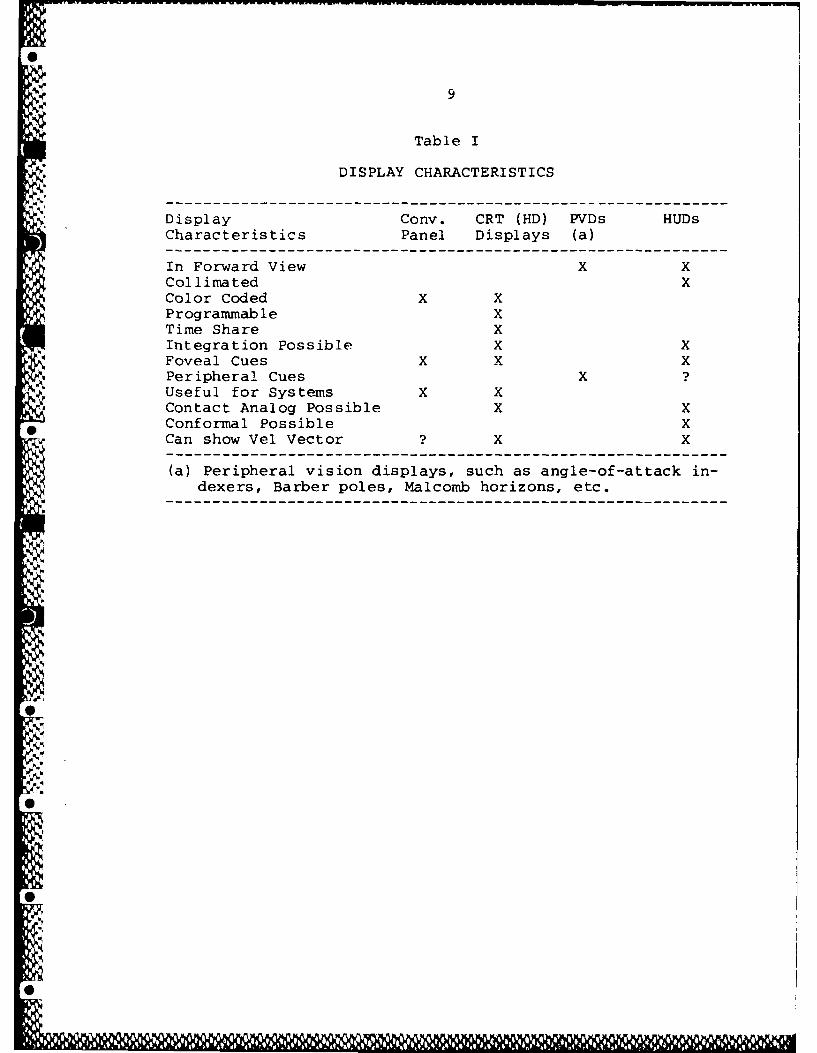
What does a HUD have that makes it unique. Table I showssome characteristics of HUDs and other displays.
The conventional panel has the characteristics of beingfixed in position with quite limited capability to be programmedfor different phases of flight. Conventional instruments are
N, capable of color coding, such as the blue/brown attitude indica-tor. They are also useful for displaying systems data. Quiteobviously, conventional instruments do not appear in the pilot's
*, view of the real world. The pilot must also look at the instru-ment to use it. We have indicated a ? for "Can show velocityvector." While no such displays have been produced to our know-ledge, they have been considered and tested (18,19). There is nophysical reason why such a display could not be produced.
tZ P

5
Head down CRT panels have many of the same characteristicsof conventional panels. In addition, it is possible to reprogramthe same display for different phases of flight. An electronicattitude (director) indicator (EADI) can display diLfferent typesand amounts of information in cruise, during an instrument ap-proach, or on takeoff. The electronic display can also generatesymbology that is an analog of the real world, the contact ana-log. This has been extended to electronic moving map displayswhich are analogs of the world when viewed from above. Finally,the electronic CRT display can integrate information (data) froma number of sources. This would include displaying velocity vec-tor.
Peripheral vision displays CPVDs) display data which do notrequire direct viewing by the pilot. By either changing the dis-play (such as angle-of-attack indexers) or moving a line in theperipheral vision (Malcomb horizon), these displays are intendedto bypass the normal cognitive processing and produce a reactionfrom the pilot. In particular, the Malcomb horizon appears tomaintain pilot orientation without requiring a conscious efforton the part of the pilot. While some displays do use color,
-~ these are primarily to reinforce a cognitive response followingan initial peripheral response. Peripheral vision is not norma-lly considered to be sensitive to colors.
HUDs share some of the characteristics of CRT displays. Theprimary such characteristics are the abilities to be programmed.to time share, and to display integrated information from a vani-ety of sources. The significant differences are the presence inthe direct view of the outside world (which is self-evident) andthe monochromatic nature of HUDs. While color HUDs have beendiscussed, it seems unlikely that a HUD will ever have the degreeof color coding available in head-down instruments, whether con-ven tional or electronic. For example, one can not employ blue to
% ~show pitch angles above the horizon because of a lack of contrast*with the sky. The advent of diffraction HUDs makes color HUDs
with more than two colors unlikely. (most head-down CRTs usethree colors to generate the images.) This will limit the numberof color cues available in HUDs of the future. One should notlook for a complete color HUD.
* Perhaps the most compelling difference between MUDs and allother displays is the ability of the HUD to display conformal im-ages which exactly overlie the corresponding objects in the pi-
-~ lot's view.*
* Parenthetically, one task of the present MUD study was de-signed to address the issue of how accurately does a runwaysymbol have to be placed to produce an acceptable HUD. Tothis end, an in-flight experiment was conducted using theUSAF variable stability NT-33A aircraft equipped with a pro-grammable head-up display (11).
-T7

6
In 1966, Col. Klopfstein, a French test pilot, developed aHIUD symbology which presented both a contact analog of the runwayenvironment and a format to directly assess the current state ofthe airplane in terms of the variables, angle-of-attack (ALPHA),flight path angle (GAMMA), and pitch attitude (THETA) (20). Thisdisplay, developed by Thomson-CSF in France allowed the pilot tofly the airplane by reference to the HUD with no numerical datadisplayed. Figure 1 shows the format. Klopfstein's approach wasto make use of the difference between flight path angle (velocityvector in our terminology) and the aircraft pitch attitude. Thedifference is exactiy the angle-of-attack:
ALPHA = THETA - GAMMA
While Klopfstein's symbology was difficult to follow -- thecoding differences between various symbols was insufficient forpilots to easily distinguish one from another -- his approach al-lowed the use of a conformal display of the three flight parame-ters most of interest to the pilot. ALPHA information ensuresadequate aircraft performance, GAMMA information shows where theairplane is going through the air, and THETA information showsthe traditional aircraft attitude. Klopfstein insisted that no"number" were necessary, and in fact none were to fly the air-plane well within accepted tolerances. However, the absence ofnumerical data limited the acceptance by operators and certifica-tion authorities.
Nevertheless, for the first time pilots had a display whichidentified the three major parameters in aircraft control and letthe pilot understand this in the scale of the real world -- notas abstract numbers on a dial. Col. Klopfstein's contribution istoo valuable to reject along with his symbology.
"-' In the 1970s, Dassault developed a similar symbology to in-corporate the best features of the Klopfstein display with numer-ical data added. The result was the PERSEPOLIS display (21).
These displays both make use of the fundamental relationship"I'. between ALPHA, GAMMA, and THETA and use air mass data. The rea-
son for this is that airplane performance is based on air massdata -- not on inertial velocities.
One other display of note is the display on the Navy A-7C/Eand the Air Force A-7D. While this display uses inertial data togenerate the velocity vector, the angle-of-attack error is shownI-by a depressed pitch attitude symbol. Because the relationshipbetween the three variables is present (clouded by the use of in-ertial data and very limited pitch information), the basic data
-I- of the Klopfstein approach is present. Some A-7 pilots have com-mented that using the standby reticle as a pitch reference allowsthem to check the angle-of-attack display. While the concept isnot taught formally, it appears that A-7 pilots absorb the rela-tionship through experience.
N -

7
Navy A-7 pilots apparently absorb enough of these conceptsto improve their no-HUD landing performance compared with theircounterparts (A-7A/B) with no HUD experience. A Navy study indi-cates that A-7C/E pilots flying night carrier approaches withouta HUD performed better than A-7A/B pilots (22). The conclusionis that having HUD experience improves pilot performance afterthe HUD is taken away.
B. VELOCITY VECTOR CONSIDERATIONS
The HUD also presents a new flight parameter -- velocityvector. This is a projection of where the airplane is going.The velocity vector is not available on any head-down panel inservice today. The velocity vector, particularly if derived fromhigh quality inertial data provides the pilot with an instanta-neous depiction of the airplane's trajectory. There are, how-ever, two problems with the use of the velocity vector as a con-trol instrument. These are the effect of large angles of attackand the effect of air mass data versus inertial data.
The velocity vector can be calculated in two fashions: airmass using pitch attitude (THETA) and angle-of-attack (ALPHA) ;and inertially using vertical velocity Vz and horizontal velocityVx. The first approach calculates the flight path angle (GAMMA)using the expression GAMMA = THETA - ALPHA. The second approachcalculates the flight path angle as GAMMA = arctan(Vz/Vx). Notethat we are assuming no lateral motion to simplify the discus-sion.
There are two myths that must be dispelled: First that in-ertial data is better than air mass data. This is not so. Airmass data is clearly supperior for determining and control air-plane performance. These aircraft are becoming increasingly sus-
.40 ceptible to windshear and downburst encounters. Some authorities
recommend the use of air mass data vice inertial data to maximizeI the recovery during these encounters. Inertial data is clearly
better for navigational purposes (including "micronavigation."They each have their place for HUDs.
The second myth is that one must have a HUD to use velocity• vector. This is also not true. Certainly, velocity vector data
is much clearer and generally useful when shown on a HUD, but airmass data does reflect aircraft performance and would be equallyuseful head-down. Many wind shear encounters for transports are
* recognized more by the effect on velocity vector than by the factthat they are shown on a HUD.

8
C. AIRCRAFT AND MISSION CHARACTERISTICS
1. Aircraft
The flying qualities of many modern fighter aircraft doesnot make these airplanes easy to fly on instruments. The mostcharacteristic feature of modern control systems is the absenceof any speed feedback through the control column. This, coupledwith a trim system designed to help maintain vertical accelera-
4 tion (Gs) rather than airspeed, makes instrument flying much moredifficult.
A second feature on these modern airplanes is their extrememaneuverability. While this is desirable duzing ACM, it is notan instrument flying enhancing quality.
These two characteristics are not fundamentally differentfor modern fighters, but they do make instrument flying more di-
-v fficult.
2. Instruments
The avionics suite of modern tactical airplanes is very com-plex. There is an increasing tendency to placing weapon or mis-sion information in the center of the instrument panel in theplace formerly reserved for the attitude indicator. The attitudeindicator has been relegated to a remote part of the instrumentpanel, sometimes between the pilots legs. Space considerationsforce the attitude indicator to be as small as possible, not aslarge as possible. It is not possible, with today's designs, tolocate the attitude indicator in the center of the panel. Thelack of space behind the panel forces the designer to locate only
A switches in this primary region of the panel -- not instrumentsneeded to fly the airplane.
3. Mission
The mission workload on the modern tactical airplane is veryhigh. The need to program the mission computer, fly the air-
* plane, keep aware of the mission environment, etc. all have theireffect. Many of the problems encountered during LOSA accidentsand incidents are directly related to workload.
9
Table I
DISPLAY CHARACTERISTICS
Display Conv. CRT (HD) PVDs HUDsCharacteristics Panel Displays (a)
In Forward View X XCollimated XColor Coded X XProgrammable XTime Share XIntegration Possible X XFoveal Cues X X XPeripheral Cues X ?Useful for Systems X XContact Analog Possible X XConformal Possible XCan show Vel Vector ? X X
(a) Peripheral vision displays, such as angle-of-attack in-dexers, Barber poles, Malcomb horizons, etc.
°I.9%
.5,o0
'.5

S
10
Ar®
.2.5
®Vvr.i>. - <
* ~~777777-
1. HORIZON LINE WITH 2 DEG. HEADING MARKS (OVERLAYS REAL HORIZON).
2. EXTENDED RUNWAY CENTERLINE.
3TRACK MARKER.4.WATERLINE SYMBOL.S.SELECTED FLIGHT PATH ANGLE (ANGLE BETWEEN HORIZON LINE AND SELECTED
FLIGHT PATH MARKER - GLIDE PATH ANGLE).6. SELECTED FLIGHT PATH MARKER (DEPRESSED BELOW HORIZON LINE AT GLIDE
PATH ANGLE).7. AIRMASS FLIGHT PATH MARKER.8. POTENTIAL FLIGHT PATH MARKER (AIRSPEED INCREASING. AIRSPEED INCREASE
WILL STOP IF THRUST IS REDUCED TO LOWER POTENTIAL FLIGHT PATH MARKERTO ALIGN WITH FLIGHT PATH MARKER, OR IF FLIGHT PATH MARKER IS RAISEDTO ALIGN WITH POTENTIAL FLIGHT PATH MARKER).
9. ANGLE OF ATTACK TRIANGLE. (ANGLE OF ATTACK LESS THAN COMMAND.COMMAND ANGLE OF ATTACK IS ACHIEVED WHEN APEX OF TRIANGLE ISTOUCHING THE FLIGHT PATH MARKER).
10. LIMIT ANGLE OF ATTACK. (LIMIT ANGLE OF ATTACK IS ACHIEVED WHEN LIMITSYMBOL IS ALIGNED WITH FLIGHT PATH MARKERI.
11. SYNTHETIC RUNWAY (THRESHOLD AT GLIDE PATH INTERCEPT POSITION).12. HEIGHT ABOVE TOUCHDOWN INDICATOR.
Figure 1
* -Klopfstein HUD Format (Reference 20)
11114 %

III. The HUD IN SPATIAL DISORIENTATION
A. BACKGROUND
VIn recent years, an increasing concern over the problem of
spatial disorientation (SDO) in modern jet cockpits has been theissue of aircraft accident investigators (13-15). While spatialdisorientation has been a difficult fact of-& fe for as long aspilots have flown in clouds, the modern problem was first voicedby Barnette (8) who performed a survey of HUD pilots for the USAFInstrument Flight Center (IFC). This survey indicated that ap-proximately thirty percent of pilots surveyed reported an in-creased tendency towards vertigo or spatial disorientation. Alater study, by Newman, confirmed, these findings (7).
The problem appears to have become more visible in recentyears. Conferences to deal with the issue of modern day spatialdisorientation have been called at Luchon (22), at Langley AFB(13), at the Pentagon (14) and at Wright-Patte-rson AFB (15).
While SDO is often considered to be a fighter issue only, infact it occurs, albeit with somewhat less frequency, in transportairplanes (23).
Spatial disorientation is only part of the problem. Manyaccidents involve a loss of awareness on the part of the pilot asto the proximity of the ground (24), the geographic location ofthe airplane (25), the performance of the airplane relative tothe terrain (26), in addition to the classic SDO upset. Examplesof each are noted. Again, both transport aircraft and tacticalfighters can be involved. The generic term loss of situational
* awareness (LOSA) can be used to describe the overall problem.SDO is but a subset of LOSA.
B. SPATIAL DISORIENTATION
* Spatial disorientation (SDO) has been a constant problem inaviation since the first flights into a cloud (probably resultingin a spiral dive out the bottom of the cloud). Spatial disorien-tation has been characterized by Benson as "a wide variety of ex-periences occurring in flight in which there is a defect in theaviator's perception of the attitude or position of his aircraftor where conflicting perceptions give rise to confusion or uncer-tainty." Sometimes the term spatial misorientation is given tosituations where the pilot has a definite but incorrect percep-tion of his attitude or position.

0 'W r
12
A good primer to review for the overall discussion of spa-tial disorientation in flight is Benson (27). Additional discus-sion can be found in Reference (22).
Orientation cues are perceived by the visual sense, by thevestibular organs of the inner ear as well as by the senses oftouch and kinesthesis. The peripheral visual cue is generallyconsidered to be the most important of these. If the perceivedbodily orientation is not appropriate for the desired function(walking, standing, sitting, etc.), appropriate motor responsesare initiated to return the body to the desired orientation.
On the ground, these various senses are usually in agree-ment. In flight (and other disorienting environments, such asskin-diving) the senses may return conflicting perceptions.These conflicting perceptions may all be incorrect. In an air-plane during flight in clouds or at night, the pilot must rely onhis instruments to determine the actual aircraft orientation. In
9 general, his orientation senses do not provide reliable percep-tions to determine his orientation in flight.
Normally the maintenance of orientation by the pilot inflight is a learned response requiring some cognitive activity.(For the purposes of this discussion, we shall assume instrumentflight unless otherwise specified.) These learned responses arecalled instrument flying skills and differ from the terrestrialorientation skills developed since childhood. In fact, instru-ment skills require that the terrestrial orientation skills besubordinated to a cognitive response.
The primary orientation sense in visual flying or in basica'terrestrial orientation is the visual sense of the horizon. In
instrument flight, however, this input is not present (In somecases it may be present, but incorrect, such as with slopingcloud tops or mountain ranges). The pilot obtains his orienta-tion via the visual sense but via the focal visual mode by fixat-ing on the attitude and other instruments and determining his at-titude by cognition. There may be some peripheral visual inputif the attitude instrument horizon line is sufficiently large and
suf ficiently obvious.
The information presented by the aircraft instruments is not* in a proper format to use his terrestrial orientation skills, so
the pilot is forced to use his instrument flying skills to main-tain orientation.
Other orientation cues are those perceptions from the yes-tibular, touch, and kinesthetic senses. Generally these do notprovide useful information during instrument flight and oftenprovide erroneous cues. The pilot is subjected to angular rota-
v tions and accelerations and to linear accelerations that he willnot experience on the ground. These cues usually are not appro-priate for orientation. As part of his instrument learning, thepilot must learn to suppress these inappropriate cues and rely on

13
the data provided from the aircraft instruments through his visu-al senses.
Much has been written about specific misleading vestibularand kinesthetic cues that cause misorientation. Some of thesedeal with interpretations of linear accelerations resulting inperception of a changing vertical orientation. Others dealwith low level angular accelerations and a perception of no angu-lar motion if a steady rotation is senses. Again, these can beamplified in a spatial disorientation source, such as Benson(27).
The sense of touch is not normally considered to be a usefulorientation cue during flight. This is not correct. Touch inthe form of stick forces (and to a limited extent stick position)provides an important feedback cue of airplane speed which inturn provides some input into orientation. Aural cues can alsoprovide some sensory input of aircraft speed from the aerodynamicnoise over the canopy. It also can provide cues as to enginethrust level.
.. In general, spatial disorientation will occur if conflictingsensory inputs are perceived and these conflicts are not resolvedby the pilot. Spatial misorientation will result if an incorrectsensory input is perceived and treated as correct by the pilot.
Some perceived sensory information is particularly trouble-some with respect to spatial disorientation (SDO). Visual nys-tagmus is an important reinforcement for SDO. This problemcaused by involuntary eye movements accompanying head motion mayhave particular HUD-related problems. Rapid changes in eye ac-commodation has been cited as a potential source for SDO (28).These may also contribute to HUD-related SDOs.
Human expectation of what the perceived sensory inputs meanmay contribute to SDO. Such problem areas as perceiving acceler-ations as tilting, apparent motion of fixed lights, and the ef-
1* fect of tilting cloud tops are examples of expectation problems.
Finally, pilot confidence in the perceived data is cited asa contributing factor in maintaining awareness. If a pilot lacksconfidence in his instruments or in instrument flying skills, hewill be more susceptible to SDO.
C. LOSS OF SITUATIONAL AWARENESS
A more generic problem of interest is loss of situationalawareness (LOSA). LOSA includes spatial misorientation and dis-
*0 orientation as subsets, but also includes those instances wherethe pilot is aware of his orientation, but either not aware ofhis position or of the proximity of the ground or other aircraft.A leading cause of these accidents is channelization of attentionand failure to monitor the progress of the flight.
"0
-5.- - V . S

14
The classic cases of LOSA deal with the controlled flightinto terrain (CFIT) accidents where the airplane flies underpilot control into the ground. Clearly in this situation, thepilot was not suffering from SDO, but rather for some reasoneither didn't know his position or was unaware of the proximityof the ground. Reference (24) describes such an accident. Thisaccident provided the impetus for the addition of ground proxi-mity warning systems (GPWS) to US air carrier transports.
In this classic CFIT accident, the pilot knew his positionreasonably well, but was confused about the minimum safe alti-tudes to be flown during an instrument approach. In the CFITaccident, it is usually stated that the airplane flies under com-plete control into a mountain. These accidents have been virtu-ally eliminated from civil air carrier records since the imple-mentation of GPWS.
In another type of LOSA accident, the pilot of a RAF Jaguarbecame confused as to the performance of his airplane. Althoughhe was well aware of the ground, confusion between the HUD pres-entation and the panel instruments led him to a loss of awareness.4% of the aircraft's performance (26).
The causes of LOSA usually training related -- complacency,confusion, lack of comprehension, or excessive workload and chan-nelized attention. One of the first priorities of a pilot is toremember that "the ground has a Pk of one."
D. EFFECT OF THE HUD
Both Newman (7) and Barnette (8) conducted surveys of pilotsflying HUD-equipped airplanes. Both surveys report that a siza-ble fraction -- thirty percent in reference (7) -- report anincreased tendency toward SDO caused by the HUD. In a later sur-vey, Newman and Foxworth (29) report a lower tendency toward SDO
* by pilots flying F-18 and Mercure airplanes. Newman and FoxworthA attribute this decline (14% of F-18 pilots, none of Mercure pi-
lots report SDO) to training or to better integration of the HUDinto the cockpit. In fact, the reason is very likely better in-tegration in the case of the F-18 and better training in the caseof the Mercure.
HUD-induced SDO is reported to result from a number of in-flight scenarios. The most common report is an increased tenden-cy while flying in-and-out of clouds. Other instances include
.-extreme maneuvers while using the HUD for flight reference, suchas night pull ups from the target, unusual attitude recovery, or
. air combat maneuvering (ACM). These are the traditional areas
for spatial disorientation in general, not just in HUD-equipped2-P airplanes.
There may be several factors causing this potentially seri-ous problem in the use of HUDs for instrument flight. The pri-
I

15
mary cause of SDO is conflicting orientation cues. According toTyler and Furr (30), the primary cause of SDO is reduced visualcues, not an abnormal stimulation of vestibular cues. What weare seeing in HUD flying is an inability of the pilot to rec'og-nize when he is in an unusual attitude (UA) and then to recoverusing the HUD. The problem arises from a variety of causes.These causes (in no particular order) are
" Lack of color codes to identify erect from in-verted flight;
" Lack of texture cues in the HUD similar to thosefound in attitude indicators to identify erectfrom inverted flight;
" Excessive amount of data present in the HUD inthe form of digital data boxes, etc., which are
& useful during selected phases of flight, but donot assist during UA recovery;
" Difficulty in assessing rate information withdigital airspeed and altitude presentations;
" Small field-of-view (FOV) combined with fullscale angles (which are helpful during normalflight) which make assessment of the overallsituation dif ficult;
" Accommodation traps in the HUD symnbology or inthe combiner structure which cause the pilotseyes to accommodate to a distance much less thanoptical infinity;
* Use of the velocity vector (GAMMA) as a controlparameter rather than as a performance parame-ter.
Any solution to enable the HUD to be useful during UA recog-nition or recovery must address these topics. It must be pointedout that many of these issues apply equally to electronic atti-tude displays (EADIs, etc.).
1. Lack of Erect versus Inverted Cues
% The conventional attitude (director) indicator (ADI) usesblack (or brown) and blue (or light grey) hemispheres to distin-guish erect from inverted flight. The ADI also provides patterns
* on one or both hemispheres to simulate ground texture or clouds.Most also use a stylized airplane symbol to emphasize aircraftattitude.
The HUD, on the other hand, is limited in that it must usemonochromatic lines and avoid texture cues which might block ex-
0

16
ternal visual cues. It is unlikely that color HUDs will be ableto provide sufficient color contrast in the near future. It isalso impractical to expect the blue or brown colors denoting skyor ground to be available for HUDs regardless of technology, be-
.cause a blue symbol would not be clearly visible against the skyand a brown symbol would not have sufficient contrast againstsome terrain features.
In this respect, HUDs are similar to first generation arti-ficial horizons. It is interesting to remember that, originally,unusual attitude recovery called for the pilot to roll to thenearest horizon. This could leave the pilot erect or inverted,however, the aircraft would be stabilized.
In place of color coding the HUD, other approaches must betaken. One is to use solid versus dashed lines above and below
0the horizon. Plus and minus numbers are used as well. It is un-likely that these can be entirely successful, by themselves, dur-
*ing the dynamic situation of an unusual attitude.
Other approaches suggest include asymmetric pitch lines (in-
verted flight places these lines on the other side of the HUD).This would make it easier to recognize erect from invertedflight, but would do little to assist in identifying extremenose-up from nose-down attitudes. A similar, but less extremeformat was proposed by Taylor of the RAE. (31-32)
Different pitch scalings above and below the horizon havebeen suggested to aid in identifying nose-high and nose-low situ-ations. The F-18 HUD uses slanted pitch lines at large pitchangles to indicate the direction to the horizon. Another cuecould be a bank index (a sky or ground pointer). Still anotherwould be to add the words "DIVE" and "CLIMB" as is done on manyADIs.
2. Clutter
During UAs, HUD clutter can prevent the pilot from inter-preting the cues needed for prompt recognition and recovery.Clutter has been defined in a draft FAA Advisory Circular as "Acluttered display is one which has an excessive amount of infor-
0 mation in the number and/or variety of symbols, colors, and spa-tial position relationships. A large fraction of this informa-tion may be pertinent to the task at hand, but if an evaluationshows that the secondary information detracts from the interpre-tation necessary for the primary task, or increases the displayinterpretation error rate, irrelevant or lower priority informa-tion should be removed."(33) The two-and-one-half degree pitchline spacing on the early F-16 HUD has been criticized in thisregard. Excessive data has also been criticized. In extremesituations, almost complete declutter (even to the point of de-leting required parameters, such as heading) may be required.
.0
Pg i1l RM I

17
3. Lack of Rate Information
The use of digital displays has been criticized by some pi-lots in making the determination of rate information difficult.
N.. This may be more of a problem with determining airspeed rate thanaltitude rate, since the velocity vector will allow the pilot tocontrol his altitude rate during normal flying. It is not clearhow this will or will not affect UA recognition and recovery.Possibly the flight path acceleration cue proposed by the Frenchcould be of some use here (20-2 1)
4. Pitch Scaling
It can be difficult to assess the situation using a fullVscale but limited FOV display. The conventional ADI is cruder,
but its compressed scale makes recovery easier. Studies havebeen performed to examine the benefits of compressed pitch scal-
0 ing during large amplitude maneuvers (34) .These results indi-cate that pitch scale compression can be a help during air combatmaneuvers (ACM) or acrobatics.
Early HUJD studies in the United Kingdom also showed that aslight pitch scale compression produced tighter approach trackingthan one-to-one scaling (4,35) . Compressed pitch scales may helpduring UA recognition or recovery as well. They have been recomn-mended by Freiburg as well (36).
5. Accommodation Issues
The issue of accommodation traps has been raised by Roscoeand others (28,37-38) . Briefly, the argument is that the HUDsymbology, in spite of being collimated, will not allow the pi-lot's eyes to accommodate to optical infinity but will focus much
* closer to a distance approximating the dark focus point (perhapsone meter in front of the pilot's eye) . This, they assert,will cause large shifts in accommodation when the pilot fixateson objects in the real world. This rapid shift in accommodationbetween HUD images and real world images can be a major cause ofvertigo.
we do not accept this argument completely. Based on inter-* views with operational pilots flying MUDs, Newman (7) found vir-
tually no mention of eye discomfort, focusing problems, or any-thing resembling accommodation difficulties. Subjectively, wefind that flight in rain in a MUD-equipped airplane allows much
*clearer view through the MUD combiner than around it. When theHUD symbology is turned off, view through the combiner or around
N' it is equally clear (about the same as the previous view aroundthe combiner. The conclusion, a subjective observation, is thatthe symbology makes the real world clearer and more in focus. Wewill suggest that the raindrops and streaks on the windshield act

18
as accommodation traps to a eye-windshield distance and that theHUD symabology act as traps to a further distance.
In any event, the resulting accommodation distance would beat least as far as the conventional instruments and there havebeen no suggestions to date that changing from head-down instru-ments to the real world causes disorientation.
A more subtle form of disorientation can result from thenarrowing of the visual field as the eye accommodates to the darkfocus point. This may produce errors in judging distance and an-gles to an outside visual target (39) . This disorientation hasno bearing on the issue of solid ins trument conditions (IMC).
6. Use of GAMMA versus THETA
one potential problem is the practice of pilots using thevelocity vector as a control parameter. During normal flight,
0 this presents no problems, but during UAs, particularly at largeangles-of-attack (ALPHAs), this can create situations where thepilot needs to push, but is pulling because of the extreme nega-tive GAMMA.
During discussions with operational fighter pilots duringthis and previous studies (7,29), it appears that they have onlya superficial understanding of-the implications of using GAMMA asa control parameter rather than THETA. Some HUDs do not evendisplay THETA.
The A-7C/D/E HUD is often criticized for having the ALPHAdisplay "backwards." This was designed to emphasize the uniquerelationship between THETA, GAMMA, and ALPHA. The Klopfstein andPERSEPOLIS HUDs, designed for transport airplanes made particularuse of this relationship (20-2 1).
E. HUD SYMBOLOGIES FOR ENHANCED UNUSUAL ATTITUDE RECOVERY
Based on results obtained in Reference (12), we can makesome recommendations for HUD formats to minimize the pilot'slikelihood of entering into an unusual attitude and maximizing
* his likelihood of recovering from the UA. It is to be rememberedthat these results are based on simulation, not flight.
1. Pitch ladder cues
* The benefit of complete lateral asymmetry was not shown bythis study contrary to what was expected from Taylor's studies(31-32). In fact, the lateral imbalance proved distracting tothe pilots. The F-18 pitch ladder with slanted pitch linespointing to the horizon was preferred by the subject pilots. italso showed a slight improvement in reaction time during UAs.
r0

19
The subjects also complained about the controlled precessionas the aircraft pitch passed through the zenith or the nadir (90degrees pi tch up oi down) . This is an artificially induced ac-tion intended to emulate the action of early attitude indicatorsas they approached gimbal lock at the 90 degree up or down atti-tude. This makes controlled flight through these points quitedifficult and is a means of inducing unusual attitudes for prac-tice (7). There is no need to maintain this controlled preces-sion in any future electronic attitude indicators or HUDs. itwas incorporated in an attempt to mimic a shurtcaning of mechani-cal instruments and has no place in electronic displays.
2. Scales format
The conventional digital airspeed and altitude scales appearto be quite satisfactory. The concept of automatic declutter or
S~. a -.witch from analog to digital does not appear to be fruitful.(This applies to airspeed and altitude scales.)
There does not appear to be a need for rate information dur-ing UA recoveries. A circular index indicating tens of knots orhundreds of feet (the minute hand) did not appear to help duringUA recoveries. It is worth examining further for routine instru-ment flight, however.
At the same time, the pitch ladder should be redrawn to en-*hance heading awareness at extreme pitch attitudes. Freiburg and
Holmstr~m evaluated an ADI with enhancedI heading information nearthe ninety degree pitch up or down point (40). A similar ap-proach would enhance HUD attitude awareness at extreme pitch at-titudes.
3. Bank information
The presence of bank information had a very positive effecton both subjective and objective results. An arrow on the velo-city vector (Augie Arrow) was clearly preferred subjectively andranked well in objective data.
* It is not clear if a sky pointer or a ground pointer is pre-ferred for a bankc scale. It should be compatible with the point-er on the head-down ADI as installed on the aircraft. It shouldalso be compatible with the arrow on the velocity vector (the Au-gie Arrow) , if incorporated. This would suggest a sky pointer.However, a ground pointer at the bottom of the FOV and a sky
* pointer on the velocity vector did not pose a problem when dis-played on the same format.
The use of a sky pointer requires that the heading scale bemodified to avoid interference. Since 7ivil HUDs use the horizonas the heading scale, this should be followed as well with a sky

20
pointer. A digital heading box above the waterline to show digi-tal heading could be helpful. The Flight Dynamics HUD for theBoeing 727 :ses a similar approach with some success (41).
4. Pitch scale compression
The use of compressed pitch scaling was well received sub-jectively by the evaluation pilots. The use of two-to-one com-pression either automatically selected or full time appears to bea likely candidate for UA recovery enhancement. It appears thatall non-ground referenced modes would be likely candidates forfull-time two-to-one scaling. It is not clear if air-to-groundmodes would benefit from such a choice.
It is clear that the use of compressed pitch scaling willrequire attention to the difference in angle between the pitchsymbol (waterline) and the velocity vector. On most HUDs, thewaterline is fixed in the FOV and the pitch ladder and velocityvector drawn relative to it. If compressed pitch scaling isimplemented in operational HUDs, it might be more desirable todraw the pitch ladder so that the horizon overlies the real worldhorizon or draw the pitch ladder such that the velocity vectorsymbol overlies the aircraft's actual velocity vector. Any ex-ternal target cues should overlie the actual location as viewedby the pilot.
The Flight Dynamics HUD uses a variable pitch compressionfor extreme nose-high or nose-low attitudes. No problems wereencountered during a simulator evaluation of this HUD (42).
5. Automatic deletion of velocity vector
One of the concerns during UAs is that the pilot will mis-use the velocity vector and pull on the stick when already at a
* high angle-of-attack. One approach to this problem is to deletethe velocity vector at large angles-of-attack. This format wasrated highly by the subject pilots and had the best objectivescores in every category. As implemented in operational HUDs,the velocity vector should be deleted when the angle-of-attack
14. reaches a value where further pull should be discouraged.
. If an Augie Arrow or angle-of-attack index is shown, theyshould be transferred to the waterline when the velocity vectoris deleted.
0<
'4..
-0'
'*.:

21
IV. TRAINING ISSUES
With our much more severe operating requirements for thepilot -- the use of a HUD with non-traditional data, airplaneswith novel handling qualities, poor instrument layouts, and ademanding workload environment, we would expect that the pilottraining in these areas would be enhanced, particularly in thearea of basic instrument training and prioritization of tasks.Unfortunately, this is not true.
A. CURRENT TRAINING
Air Force pilots are generally not as well trained in basicinstrument flying today as they were several years ago. There is
more to learn and less time to learn it in. Pilots graduatingfrom undergraduate pilot training (UPT) today have approximately12 hours of instrument flying time in airplanes and about thirtyhours in simulators. Interestingly, this is not enough to quali-fy them to fly a Cessna 150 under IFR in civilian operations.
What is, perhaps more critical, is the almost complete lackof emphasis on flying by means of electronic displays, particu-larly the HUD. There is no question that the techniques usefulin HUD instrument flying are different than those useful in panelinstrument flying (so-called vector instrument flying versus at-titude instrument flying). At present, the only guidance offeredby the USAF on using HUDs for instrument flying is cautionary.Yet, admittedly, most pilots find the HUD works for them most ofthe time and works quite well. As a result they use it and teachthemselves how to fly. Unfortunately, in some areas (such as thehigh ALPHA unusual attitude described above) the system breaksdown.
B. HUD TRAINING
There is concern expressed among the more experienced pilotsthat teaching using the HUD will make the pilot dependent on theHUD. We disagree. The pilot will become no more dependent onthe HUD than he is dependent now on the attitude indicator. Fur-ther, a Navy study indicates that having a HUD available makespilots perform better when the HUD is not available (22). Thisstudy used Navy A-7 pilots, half of whom had flown the A-7A/Bwithout a HUD and half who had flown the A-7C/E with a HUD. Whenflying simulated night carrier landings without a HUD, the A-7C/Epilots performed better. These results argue against the conceptof a pilot becoming over-dependent on th- HUD.
NM

MM x g wnt- '~ rnn
22
We have already discussed the need for the pilot to learn tomake small corrections and to not be overwhelmed by the apparentlarge amount of movement of the HUD symbols. Subjectively, wehad an early HUD instructor who would admonish us to "fly loose"We have also observed a tendency for pilots to over-zealouslyconcentrate on minimizing airspeed and altitude errors -- down tothe last knot or foot -- if digital data is provided. New pilotsmust be trained to avoid this.
Newman's earlier study (7) indicates that it takes a pilotabout 300 hours to learn to use the HUD and associated systems.It would be interesting to see how fast he could learn givensuitable instruction and how well he would understand.
The French domestic airline, Air Inter, uses a HUD-equippedtransport, che Mercure. Their HUD training syllabus takes fouror five days devoted to the HUDl alone (43). This training occursafter the pilots have about 200-300 hours on the airplane. Muchof the training is simulator training which emphasizes the effectof winds and failure states. The system on the Mercure is an airmass HUD so the effect of winds is not obvious to an untrainedpilot and could be confusing until he understands what the datameans. The simulator training begins with a normal no-wind ap-proach and then follows with an approach with a ninety knot windto make it quite clear to the pilot what is happening. Air Interand Swissair have the most advanced HUD training today (albeitthe only serious HUJD training).
The French do not cover one area seen as a problem. This ishow to look "through" a HUD. The skill can be likened to learn-ing how to look "through" a gunsight when learning to shoot orlooking "through" a microscope keeping both eyes open. This pro-cess is self-taught at present (perhaps those pilots who areanti-MUD never really learned how to do this). This skill re-
'A quires an airplane and can not be done in a simulator.
* In personal experience with HUD flying, we have found thatthe ability to separate external visual cues and internal HUDcues is the main form of learning that is experienced duringearly HUD experience. Additionally, pilots new to HUDs mustlearn to rescale their inputs. The motion of the HUD cues isperceived to be much more rapid and frantic than the conventional
*instruments. New HUD pilots have a greatly increased workloadtrying to overcorrect these apparent large excursions from nomi-nal flight. This is also evident with those MUDs having digitalairspeed and altitude scales. These problems disappear with HUDexperience.
*The HUD (and electronic attitude displays in general) pre-sent additional difficulties to the pilot -- difficulties notfound in conventional panel instruments. The HUD, in particular,does not present a pilot with a clear presentation of pitch atti-t-11de. The MUD has no color cue to show the difference betweennose high and nose low as does the conventional ADI. The lines
0IIR) I

23
are perceived as being identical (even though nose low lines aredashed.) This makes recognition of aircraft orientation in unu-sual attitudes difficult and will tend to delay recovery.
The HUD also presents a new flight parameter: velocity vec-tor. This is a projection of where the airplane is going. Thevelocity vector is not available on any head-down panel in ser-vice today. The velocity vector, particularly if derived fromhigh quality inertial data provides the pilot with an instantane-ous depiction of the airplane's trajectory. There are, however,two problems with the use of the velocity vector as a control in-strument. These are the effect of large angles of attack and theeffect of air mass data versus inertial data.
When the pilot flies using GAMMA as a control parameter, heis in effect using the vertical velocity as a control parameter.This produces acceptable results in irr.st instances. Unfortunate-ly, when ALPHA is large or is changing, the use of GAMMA as acontrol variable can result in incorrect control inputs. Thesame problem would result if a pilot used vertical velocity as a
-" longitudinal contrcl parameter in contravention of AFM-51-37',p. (44).
The situation would become the most extreme in a high angle-of-attack unusual attitude recovery. The aircraft nose would beup (above the horizon) while the trajectory would be down (verymuch below the horizon). The pilot, overtrained on using GAMMAas a control parameter would try to recover by pulling on the
"'. stick thus aggravating the already high angle-of-attack. The*1 correct recovery would be to lower the nose (to decrease the an-
gle-of-attack) and add thrust to minimize loss of altitude. Useof head down panel instruments would produce the correct response(assuming the pilot did not attempt to use vertical velocity as acontrol parameter).
* C. WHEN TO INTRODUCE THE HUD
It is not clear when the HUD should be introduced to the pi-lot -- early in his basic training or later as part of the air-
craft checkout. Current US military practice is to introduce theHUD as part of the aircraft checkout. A strong case could be
* made to introduce the pilot to the HUD as soon as possible -- in-'i primary or basic training -- since many new pilots will only be
flying HUD and electronic display equipped airplanes throughouttheir careers. The Navy study cited above indicates that theother pilots (not flying HUD and electronic equipped airplanes)will actually have an easier task adapting to the "round dial"airplanes than today's HUD pilot has adapting to the HUD.
The most advanced HUD training at present is being conductedby Air Inter and Swissair. Clearly, these two airlines feel thatsimultaneous introduction of a new airplane and a new concept offlying (the HUD) is too much at once. Air Inter delays introduc-

24
tion of the HUD for several months after the pilot becomes quali-fied on the airplane. This is one approach. It does mean thatpilots who are already HUD-qualified on another airplane will notbe able to use this background from the start or will require adifferent check-out syllabus.
A second approach, which make more sense, it to introducethe HUD earlier. A dedicated HUD instrument course would outlinethe special techniques of HUD instrument flying. This could beaccomplished in a trainer ur in a simulator. The Canadian Forcesare examining the concept of a HUD-equipped instrument trainer(Canaaair CT-114) to teach the pilots how to fly instruments us-ing the HUD prior to their checkout in HUD-equipped fighters.Pilatus Aircraft is marketing a HUD equipped trainer, the PC-9.At this writing, several have been sold to third world air forc-es. Other air forces are considering using HUDs during pilottraining as well.
D. THE HUD IN BASIC TRAINING
There is a place for a HUD during initial pilot training.First, with most new airplanes going to the glass cockpit, itmakes more sense to start the pilots on electronic instruments
from the start rather than conventional instruments. This willminimize the need to unlearn round dial skills and then relearnthe basic electronic instrument skills.
The argument is that the pilot will become "overdependent onthe HUD." This is a specious argument. As we have seen earlier,based on Navy experience, having HUD experience helped the pi-lots' performance when the HUD was no longer available. Thisdoes not appear to be "overdependence." (We also do not seem to
, worry about pilots becoming overdependent on the ADI.)
Another strong argument in favor of having a HUD during ini-tial pilot training would make use of the ability to display AL-PHA, GAMMA, and THETA directly in a full scale picture. Based on1200 hours of primary instruction, we feel that this would be avery valuable training tool for UPT students.
* E. THE HUD PROCEDURES TRAINER
We feel that there is a definite need for a HUD procedurestrainer at at least the advanced trainer level. This airplaneshould be equipped with a full suite of head=up and head-down CRTdisplays and should be able to emulate the various symbologies in
O the fleet (although increased standardization should minimizethis requirement). The mission of this airplane should be (1) toprovide basic introduction to HUD instrument flying; (2) to pro-vide recurrent HUD instrument checks; and (3) to develop adequateHUD instrument procedures. It should also include some form ofcomputer navigation system to acquaint the student pilot with the
10

25
data entry and monitoring requirements of modern inertial naviga-tional systems (INSs) and their computers.
A great deal of the problem inherent in modern military air-planes is the high workload of the weapon systems themselves.Often these require considerable effort in inputting data to theon-board computer and in monitoring the systems data. The skillsneeded to accomplish these tasks are not the same skills empha-sized in flying training.
Many of the tasks required are weapon system specific. Nev-ertheless, there is a common thread of the problems. There is aneed to learn how to prioritize attention and workload capacityto accomplish the primary job of the pilot -- keep the airplanefrom flying into the ground!
This training could be accomplished using a generic weaponsystem computer -- to teach the fledgling pilot how to allocatehis cognitive resources to his tasks and maintain his awareness.
* This would be similar in scope to fighter lead-in training (LIT).In LIT, the student pilots fly generic mission profiles and usegeneric tactics in T-38s.
Perhaps the closest approach to this type of training is the
low-level awareness taught at Tucson by the Air National Guard.
This may be expensive, but not as expensive as on the job
training as is done today. Such a HUD procedures trainer wouldbe cost effective in the long run -- even without considering thesavings in lost airplanes and crew.
,
AS
O
6

26
V. CONCLUSIONS
The following conclusions can be drawn:
* The HUJD is not inherently unsafe and is quitesuitable for use as a primary flight display inIMC.
* The use of air mass data vice inertial velocityvector data has certain advantages in somesituations.
0 Current military instrument training is* inadequate both in terms of initial pilot
training and recurrent training.
0 The specific techniques required for head-updisplays are exacerbated by the lack ofadequate training. This lack of HUD trainingborders on the irresponsible.
* The use of a generic HUD procedures trainer isheavily recommended.
* A library of HUD symbologies should be devel-oped for use in this trainer.
P1

27
VII. REFERENCES
1 J. M. Naish, System for Presenting Steering Information Dur-ing Visual Flight: Part I, The Position of Presented Infor-mation, RAE-TN-IAP-1132, October 1961
2 J. M. Naish, System for Presenting Steering Information Dur-ing Visual Flight: Part II, The Form of the Presented Infor-mation, RAE-TN-IAP-1138, February 1962
3 J. M. Naish, System for Presenting Steering Information Dur-ing Visual Flight: Part III, The Influence of Errors andLimitations, RAE-TR-64026, October 19640
4 A Comparison of Electronic World and Flight Director WorldHead-Up Display: Their Installation and Philosophy, ElliottBrothers ADD-229, April 1968
5 J. M. Naish, "The Flight Simulator in Display Research,"Journal of The Royal Aeronautical Society, 68, 1964, 653-659
6 E. Fischer, R. F. Haines and T. A. Price, Cognitive Issuesin Head-Up Displays, NASA-TP-1711, December 1980
7 R. L. Newman, Operational Problems Associated with Head-UpDisplays During Instrument Flight, AFAMRL-TR-80-116, October1980
' 8 J. F. Barnette, Role of Head-Up Display in InstrumentFlight, AFIFC-LR-76-2, August 1976
9 R. L. Newman, Head-Up Display Design Guide, Crew Systems TR-87-15, June 1987
10 R. L. Newman and R. E. Bailey, Head-Up Display DynamicsFlight Tests, Crew Systems TR-87-12, June 1987
11 R. L. Newman and R. E. Bailey, Head-Up Display AccuracyFlight Tests, Crew Systems TR-87-13, June 1987
*5 12 R. L. Newman, Evaluation of Head-Up Displays to Enhance Un-usual Attitude Recovery, Crew Systems TR-87-14, June 1987
13 Proceedings of the HUD/Instrument Conference, Langley AFB,TAC Headquarters, June 1983
14 Flight Instrumentation Conference, Pentagon, US Air Force,June 1985
..... ... ....- - -

28
15 Spatial Disorientation Conference, Flight Dynamics Labora-tory, AFWAL, October 1985
16 A. C. McTee, D. L. Carmack, and R. K. Taylor, HUD Investiga-tion in Low Visibility, IPIS TR-71-3, June 1971
17 P. Hameluck and P. Stager, "The Peripheral Visual HorizonDisplay: A Review," Proceedings 4th International Symposiumon Aviation Psychology, Columbus, April 1987
18 K. R. Woodruff, Use of Flight Path Angle on the Attitude
Ball, Systems Research Laboratories TM-2, October 1970;Report for Contract F33615-69-C-1595
19 J. F. Barnette and G. Intano, Determining the Utility of Ex-panded Pitch Scale and Flight Path Angle as Display Parame-ters, AFIFC-TR-76-4, October 1976
20 G. Klopfstein, "Rational Study of Aircraft Piloting," INTRA-DOS, 1966; reprinted by Thomson-CSF
21 H. Suisse, Head-Up Display System -- PERSEPOLIS Symbology,Dassault Report DGT-16433, September 1979
22 "A Word from the Navy," ALPA Head-Up Display Newsletter,January 1979, pp. 30-31
22 A. J. Benson (ed.), The Disorientation Incident, AGARD-CP-95-Part I, March 1972; papers presented at Aerospace MedicalPanel Specialist Meeting held in Luchon, France, September1971
23 Aircraft Accident Report: China Airlines Boeing B747SP,N4522V, 300 NM Northwest of San Francisco, February 19,1985, NTSB-AAR-86-03, March 1986
24 Aircraft Accident Report: Trans World Airlines Boeing B727-V. 231, N54328, Berryville, Virginia, December 1, 1974, NTSB-
AAR-75-16, November 1975
25 Boeing 727-100,G-BDAN, Accident Near Teneriffe North Air-* port, The Canar-y Islands, on 25 April 1980, Spanish Accident
Investigation Commission Report, July 1981; in ICAO AircraftAccident Digest No. 27, ICAO Circular 178-AN/ll, 1984
26 "Jaguar Hit Trees," Flight International, 19 July 1986; Sum-mary of RAF Accidernt Investigation Board investigating acci-
*• dent to RAF Jaguar GR.1A in West Germany, July 9, 1985
27 A. J. Benson, "Spatial Disorientation in Flight," in Avia-tion Physiology, J. A. Gillies (ed.), London: PergamonPress, 1965, pp. 1086-1129

%. 29N
28 R. J. Randle, S. N. Roscoe, and J. Petit, Effects of Accom-modation and Magnification on Aimpoint Estimation in a Simu-lated Landing Task, NASA-TP-1636, October 1980
29 R. L. Newman and T. G. Foxworth, A Review of Head-Up DisplaySpecifications, Crew Systems TR-84-04, April 1984; final re-port for contract F33615-83-C-5124
30 P. R. Tyler and P. A. Furr, "Disorientation: Fact and Fan-
cy," in The Disorientation Incident, AGARD-CP-95; Reference1.
31 R. M. Taylor, "Some Effects of Display Format Variables onthe Perception of Aircraft Spatial Orientation," AGARD Sym-posium on Human Factors Consideration in High PerformanceAircraft, Williamsburg, April/May 1984
32 R. M. Taylor, "Attitude Awareness from Aircraft Head-Up Dis-- play," Proceedings Fourth International Symposium on Avia-
tion Psychology, Columbus, April 1987
33 Display Factors for Electronic Flight Instrument Systems,FAA Draft Advisory Circular, June 1985
34 S. J. Monagan and R. E. Smith, "Head-Up Display Flightp. Tests," Proceedings 24th Annual Symposium Society of Experi-
mental Test Pilots, Beverly Hills, September 1980, pp. 75-87
35 J. M. Naish, Properties and Design of the Head-Up Display,McDonnell-Douglas Report MDC-J1409, April 1968; revised Feb-ruary 1970; also published as Douglas Paper 4951
36 U. Freiburg, "Basic About Scale One-to-One Head-Up Display,"Proceedings 15th Annual Symposium Society of ExperimentalTest Pilots, Beverly Hills, September 1971, pp. 77-85
* 37 S. N. Roscoe, "Bigness is in the Eye of the Beholder," HumanFactors, 27, 1985, 615-636
38 J. H. Iavecchia, Response biases with Virtual Imaging Dis-plays, NADC-85165, June 1985
* 39 J. H. Iavecchia, The Potential for Depth Perception Errorsin Piloting the F-18 and A-6 Night Attack Aircraft, NADC Re-port, in preparation
40 U. Freiburg and S. Holmstrm, "An Ordinary 3-Axis HorizonInstrument Which Every Pilot Likes -- Can It Be Misleading
_ and Dangerous? The Answer is 'Yes'," Proceedings 30th An-nual Symposium Society of Experimental Test Pilots, BeverlyHills, September 1986, pp. 187-199
41 Head-Up Guidance System, Flight Dynamics, Inc. Pilot Guide,n. d.
0•

0~vW KWF1VWY
30
42 R. L. Newman, An Evaluation of the FDI Head-Up Display CrewSystems TM-87-04, January 1987
43 Programme Simulateur -- Approche Automatigue Mode Land, AirInter Manuel de L'Equipage Mercure, January 1979
44 Instrument Flying, AFM-51-37, July 1986
*ubGvrretPitn ffc:18 4-5/05
I*1111s

44
.DA
/S
• __S01