Embed Size (px)
Citation preview
IoT Technology Day
COMPANY RESTRICTED

Agenda
ı Emerging wireless technologies for IoT
ı WLAN, Bluetooth
ı ZigBee today and tomorrow
ı LP-WAN technologies Sigfox, LoRA
ı Testing aspects in IoT
ı RF parametric tests – Tx and Rx measurements
ı Over the Air (OTA)
ı Interference and Co-existence
ı Conformance and Carrier Acceptance tests
ı Effectiveness of accurate measurement in production environment
ı Latest Trends - Multi Device testing
ı Complete Turnkey Solution

Technologies for diverse IoT application,
but no single technology for every use case
Data Rate
Smart Cities Smart Homes
Wearables Automotive
Ran
geCellular
(2G/3G/4G/5G)
NFC
ZigBee
Thread
Z-Wave
WI-SUN
802.11 ahWi-Fi
802.11 a/b/g/n
(802.11ac/ax)
Sigfox
LoRa
Weightless
NB-IoT
eMTC
ANT+
Bluetooth

WiFi, a main enabling technology for the IoT
ah
af
TVWS; 6,7,8 MHz
<1GHz; 1,2, (4,8,16) MHz
ad
60 GHz; 2.16 GHz; Beamsaj
50-60 GHz; 1.08 GHz; Beams
Room/Desk Area Network
M2M& IoTNetworks
ac1 ac2
5 GHz; 80MHz; SU-MIMO 5 GHz; 160MHz; MU-MIMO
Home/OfficeNetworks
p
5.9 GHz; 10MHz
Vehicle Networks
ax
ay
60 GHz; 8.64 GHz; Beams
1….6 GHz; 160MHz; OFDMA, MU-MIMO

Wi-Fi is used for several IoT applications, especially
in smart home and smart office environment today802.11a 802.11b 802.11g 802.11n
Frequency 5 GHz 2.4 GHz 2.4 GHz 2.4/5GHz
Channel bandwidth 20 MHz 20 MHz 20 MHz 20 MHz, 40 MHz
Spatial streams 1 1 1 1,2,3,4
Max. Data rate 54 Mbps 11 Mbps 54 Mbps 600 Mbps
MAC CSMA/CA CSMA/CA CSMA/CA CSMA/CA
System OFDM DSSS OFDM, DSSS OFDM, OFDMA
Duplex TDD TDD TDD TDD
Max. Power
(typ.)
1 W
(100 mW)
1 W
(100 mW)
1 W
(100 mW)
1 W
(100 mW)
Modulation BPSK, QPSK,
16QAM, 64QAM
CCK CCK, BPSK, QPSK,
16QAM, 64QAM
BPSK, QPSK,
16QAM, 64QAM

WLAN signaling to emulate a WLAN network
R&S®CMW500/270
The all-in-one test platform
• WLAN Signaling functions to emulate access point (AP) or station (STA) functionalities
• Packet generation (e.g. Ping)
• Online message tracing
• End-to-end data applications
• Support of offloading scenarios
Access Point Emulation BSS Station Emulation
IBSS Station Emulation
ad hoc network
WiFi Direct Emulation
Group owner emulation
AP STA
STAGO
(group owner)
802.11 a/b/g/n/ac 802.11 a/b/g/n/ac
802.11 a/b/g/n /ac* 802.11 a/b/g/n /ac*
APSTA
STA client

Wi-Fi HaLow„New technology will extend Wi-Fi® solutions for the Internet of Things” Wi-Fi Alliance (Jan.2016)
Sensor Networks WearablesHome Security Range extension Smart Metering
Long range operation
Large number of devices per access point
Low power consumption
High throughput compared to e.g. ZigBee
Greenfield operation
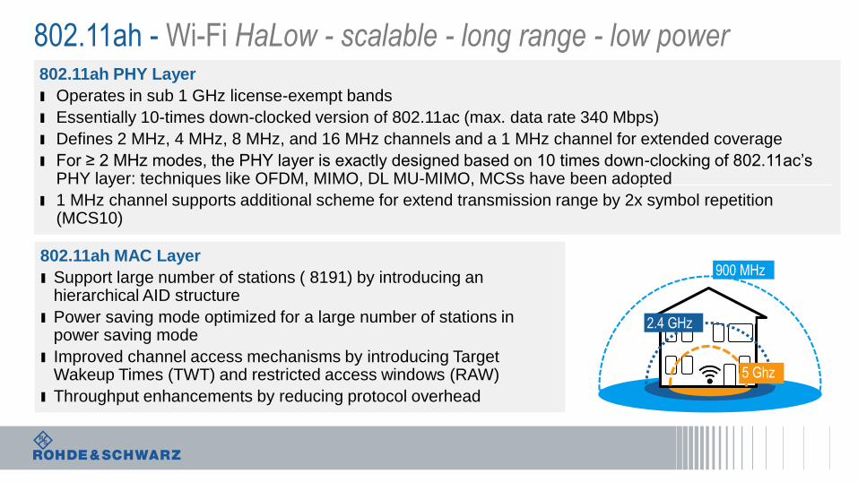
802.11ah - Wi-Fi HaLow - scalable - long range - low power 802.11ah PHY Layer
ı Operates in sub 1 GHz license-exempt bands
ı Essentially 10-times down-clocked version of 802.11ac (max. data rate 340 Mbps)
ı Defines 2 MHz, 4 MHz, 8 MHz, and 16 MHz channels and a 1 MHz channel for extended coverage
ı For ≥ 2 MHz modes, the PHY layer is exactly designed based on 10 times down-clocking of 802.11ac’s PHY layer: techniques like OFDM, MIMO, DL MU-MIMO, MCSs have been adopted
ı 1 MHz channel supports additional scheme for extend transmission range by 2x symbol repetition (MCS10)
802.11ah MAC Layer
ı Support large number of stations ( 8191) by introducing an hierarchical AID structure
ı Power saving mode optimized for a large number of stations in power saving mode
ı Improved channel access mechanisms by introducing Target Wakeup Times (TWT) and restricted access windows (RAW)
ı Throughput enhancements by reducing protocol overhead
5 Ghz
2.4 GHz
900 MHz

Spectrum is a scarce and valuable resource
Low Spectrum (<1GHz) is even more valuableMotivation:
• Superior propagation characteristic of low frequency band
• Legacy spectrum bands are under-utilized
Sharing @ location and/or @ time.
• Spectrum Sensing & Geo-location databases
frequency
time
power

802.11af in a nutshell
ExtendedHome network
Rural Broadband
Outdoor Sensor Networks
Public WiFiextension
Public Safety networks
• Operates in TV bands (54-698 MHz)
• Essentially down-clocked version of 802.11ac – 40 MHz (max. data rate 384/569 Mbps)
• Use of 144 SC per BCU (not 128), for 55db Adjacent Channel Leakage Ratio
• Defines 6 MHz, 7 MHz, 8 MHz channels (region specific)
• Supported channelization: W, W+W, 2W, 2W+2W, 4W

802.11af - principle
802.11af PHY Layer
ı Operates in TV bands (54-698 MHz)
ı Essentially down-clocked version of 802.11ac – 40 MHz (max. data rate 384/569 Mbps)
ı Defines 6 MHz, 7 MHz, 8 MHz channels (region specific)
802.11af MAC Layer
ı Operation under the control of a Geolocation DB (GDB)
GDB GDD enabling STA
GDD dependent STA
RLSS
IETF PAWS Protocol

11af is using 144 (168) subcarriers to ensure
e.g. 55dB Adjacent Channel
TVHT-6 MHz TVHT-7 MHz TVHT-8 MHz
# of subcarriers per BCU 144 168 144
# of data subcarriers 108 108 108
# of pilot subcarriers 6 6 6
SC spacing 41.66 kHz 41.66 kHz 55.55 kHz
Guard Interval Duration 6 µs 6 µs 4.5 µs
12.06.2017
6 MHz144 SC
5.333 MHz128 SC
4.833 MHz116 SC
12.06.2017
8MHz144 SC
7.111 MHz128 SC
6.444 MHz116 SC
5.333 MHz128 SC
4.833 MHz116 SC
7 MHz168 SC
12.06.2017
40 MHz128 SC
40 MHz128 SC
36.25 MHz116 SC

Car (Vehicle) to X, communication based on 802.11p
►WiFi in a very challenging environment
LOSnLOS
802.11a signal with reduced rate: • 10 MHz bandwidth for robustness • Carrier spacing reduced by ½ • Symbol length is doubled, making the signal
more robust against fading. • Operates in the 5.8 GHz and 5.9 GHz
frequency bands depending on regional regulations.
• 802.11p is essentially based on the OFDM PHY
Wave mode: • direct data exchange between vehicles using
a wildcard BSSID
Very High
relative speed

ZigBee today and
tomorrow Bluetooth entering
the smart home
Wi-Fi – the natural
home network
Emerging technologies for IoT

Bluetooth Classic and Bluetooth Smart serving the wearable market
2 400 2 420 2 440 2 460 2 480 MHz
Bluetooth Smart (BLE)
• 2.4 GHz ISM band
• 1 Msymbol/s using GFSK modulation
• 40 channels on 2 MHz spacing
• 3 advertising channels
• Frequency hopping (37 channels)
• CRC
Bluetooth Classic (BR+EDR)
• 2.4 GHz ISM band
• 1 Msymbol/s using GFSK modulationEDR: data modulation π/4-DQPSK / 8DPSK
• 79 channels on 1 MHz spacing
• Frequency hopping (1600 hops/s)
• Voice support
• FEC
voice
text

Bluetooth SIG focus on enhancements for the IoT
Range
Meshbuilding meshed
network using relay
nodes
SpeedSupport of 2 Mbps
GatewayConnecting
devices directly to
the cloud
4x range to cover a
smart home or office
DirectionExtended broadcast
capabilities of beacons
“Bluetooth is on the threshold of being the enabling wireless technology for the IoT.” Bluetooth co-inventor Sven Mattisson
COMPANY RESTRICTED

Bluetooth 5.0
COMPANY RESTRICTED

Bluetooth 5: 8 times broadcast capacity
Using channels 0..36 as secondory Advertising channels
37 0 1 2 3 4 5 6 7 8 9 10 38 11 12 13 14 15 16 17 18 19 20 21 22 23 24 25 26 27 28 29 30 31 32 33 34 35 36 39
Primary Advertising
Secondary Advertising
Data Channels
Primary advertising channels are used for all advertising broadcasts
use either the LE 1M or LE Coded PHY; packets can vary in length from 6 to 37 octets.
Secondary advertising channels are introduced to offload data
use any LE 1M, LE 2M or LE coded PHY; packets can vary in length 0 to 255 octets

Challenges with BT-LE devices – how to setup physical control
line connection ?
An OTA solution for BT-LE based on the advertiser
COMPANY RESTRICTED

Test Bluetooth 5 already today with solutions from R&S
The solutions cover all RF tests defined by Bluetooth SIG,
from Bluetooth Basic Rate V1.2 all the way to the new
Bluetooth 5 specification for low energy.
I Testing the new Low Energy PHY (LE 2M)
supporting 2Mbps data throughput
I Measure the new Low Energy long range PHYs
(LE coded) performance as well TX power/modulation
and ACP TX
I Support of stable modulation index applicable for all
Low Energy PHYs (LE 1M, LE 2M) R&S®CMW270

CMW supports all Bluetooth RF Test cases
BR
EDR
LE
BR + EDR
additional SGs and SA needed
see Application Note 1MA106
LE
additional SGs needed
see Application Note 1MA200Blocking Performance test fully
automated in CMWrun
COMPANY RESTRICTED

ZigBee today and
tomorrow
Bluetooth entering
the smart home
Wi-Fi – the natural
home network
The wireless Internet of Things
Technologies for the smart home

802.15.4 – for smart home , smart buildings and more
IEEE 802.15.42.4 GHz O-PQSK
6LoWPAN, DTLS, Distance Vector Routing
Protocol (e.g. CoAP)
UDP/TCP
802.15.4 MAC
IEEE 802.15.42.4 GHz O-PQSK
6LoWPAN
ISA Protocol
802.15.4 MACUpper data link ISA100
UDP
IEEE 802.15.42.4 GHz O-PQSK
HART Addressing/Routing
HART: TCP like
HART TDMA - hoping
IEEE 802.15.4 2.4 GHz O-PQSK
ZigBee - Networking
ZigBee - Protocol
ZigBee - Transport
802.15.4 MAC
HART: Protocol

ZigBee Technology Facts: Reliable, Low Power, Cost Effective
IEEE 802.15.4 MAC
IEEE 802.15.42400 MHz
IEEE 802.15.4868/915 MHz
ZigBee Network Layer
Applications
ZigBee Application Layer
2405 MHz 2480 MHz
2.4 GHz/16 Ch.; World; OQPSK; 250 kbps868 MHz/1Ch.; Europe
BPSK 20kbps
868.3 MHz 906 MHz
915 MHz/10 Ch.; Americas;
BPSK 40kbps
924 MHz
Coordinator
Router
End Device
Meshed Network of thousands of devices

802.15.4: 2.4 GHz ISM Band 16 Channels O-QPSK 250kbps
1
0
1
0
1
0 0
1
0 0 0
1
0
1 1 1
1 1
0
1 1
0 0
1 1 1
0 0 0 0
1
0
I
Q
1 1 0 1 1 0 0 1 1 1 0 0 0 0 1 1 0 1 0 1 0 0 1 0 0 0 1 0 1 1 1 0bin
0 hex
Bits (4) to
Symbol
Mapping0 0 00
250 kbit /s
Symbol to
Chip (32)
Mapping
O-QPSK
modulator
62.5 kSym/s 2 Mchip/s
I
Q
11
1000
01
The transitions of I and Q are offset by half of the symbol time (Ts/2) with O-QPSK (Offset Quadrature Phase Shift Keying). Together with the half-sin filter that eliminates any amplitude variations and turns the O-QPSK into a constant envelope modulation.

R&S®CMW100,
R&D and manufacturing solution for 802.15.4 applications
CMW-KM680 Tx measurement for 802.15.4
CMW-KV680 Waveform for ARB Generator
Power Spectral Density
EVM vs. Chip
Power vs. Time IQ Constalation
Tx Modulation
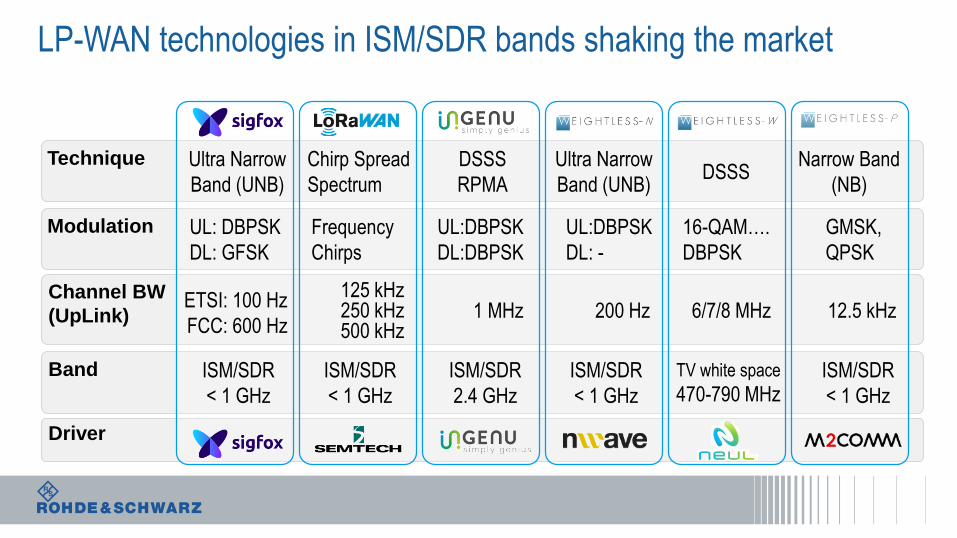
LP-WAN technologies in ISM/SDR bands shaking the market
UL: DBPSK
DL: GFSK
Frequency
Chirps
UL:DBPSK
DL:DBPSK
16-QAM….
DBPSK
UL:DBPSK
DL: -
GMSK,
QPSK
Modulation
Channel BW
(UpLink)ETSI: 100 Hz
FCC: 600 Hz
125 kHz 250 kHz 500 kHz
1 MHz
Ultra Narrow
Band (UNB)
Chirp Spread
Spectrum
DSSS
RPMADSSS
Ultra Narrow
Band (UNB)
Narrow Band
(NB)
200 Hz 12.5 kHz6/7/8 MHz
Technique
ISM/SDR
< 1 GHz
ISM/SDR
< 1 GHz
ISM/SDR
2.4 GHz
ISM/SDR
< 1 GHz
ISM/SDR
< 1 GHz
TV white space
470-790 MHz
Band
Driver

Object
(Sensor)
Example: Sigfox designed as LP-WAN sensor network
Ultra Narrow Band
Modulation
(100 Hz / 600 Hz)
Redundant uplink
Transmission
(2x repetitions)
Pseudo–random
frequency hopping
(3 out of 320 ch.)
Short messages
UL: 12 Byte
DL: 8 Byte
No passive RX
mode (RX window
after TX)
8 Byte / max 4 per day* | 600 bps | 2GFSK / 800 Hz | < 27 dBm
12 Byte / max 140 per day* | 100 bps | (D)BPDK | < 14 dBm Gateway
Backend
Server
~2sec ~2sec ~2sec
100Hz
* ETSI regulation

LoRaWAN Network architecture
Pet TrackerSmart Meter
Trash CanPlant Sensor
SuitcaseSmoke Detector
LoRa Gateway
LoRa Gateway
LoRa Gateway
LoRa RF | LoRaWAN TCP/IP SSL | LoRaWAN TCP/IP SSL | Secure Payload
App
ServerApp
ServerApp
Server
App
Server
App
Server
LoRaNetwork Server(home)
LoRaNetwork Server
(serving)
JoinServer

Object
(Sensor)
LoRaWAN
Chirped Spread
Spectrum
(125/250/500 kHz)
Multiple Gateways
simultaneously
receiving
Pseudo–random
frequency hopping
(after each TX )
Data Rate Adaption
(spreading factor/
bandwidth)
Different RX mode
options
(Class A/B/C)
Gateway
Backend
Server< 11kbps | < 1% duty cycle | CSS | < 14 dBm*
0 kHz
+250 kHz
-250 kHz
Constant chirp rate (Hz/µs) defined by Spreading Factor (SF)
< 11kbps | < 1% duty cycle | CSS | < 27 dBm** ETSI regulation
Symbol Duration (Ts)

Pow
er
Late
ncy
Three Classes of Devices: Class A communication is mandatory
Class ABi-directional communications is allowed
whereby each end-device‘s uplink
transmission is followed by two short
downlink receive windows (RX1 & RX2).
Class BIn addition to the Class A random receive
windows, Devices open extra receive
windows at scheduled times, synchronized
by periodic Beacons from the gateway.
Transmit
Receiver D.
Receiver Delay2
RX1 RX2
Transmit
Receiver D. 1
Receiver Delay2
RX1 RX2RX2
Receiver Delay1
Ping Period(1..128 sec.)
BeaconRXslot RXslot RXslot Beacon
Beacon Period (128 seconds)
RXslot
Class CEnd-devices of Class C have nearly
continuously open receive windows (RX2),
only closed when transmitting.

LoRa Europe 868 Mhz ISM band (ETSI)
865864 866 867 868 869 870
Data Rate Channel BW Spreading Phy bit rate
DR0
125 kHz
SF12 250 bps
DR1 SF11 440 bps
DR2 SF10 980 bps
DR3 SF9 1 760 bps
DR4 SF8 3 125 bps
DR5 SF7 5 470 bps
DR6 250 kHz SF7 11 000 bps
DR7 FSK: 50 kbps 50 000 bps
Default radiated transmit output power: 14 dBm
• 20 dBm if allowed (G3)
TransmitReceiver Delay1
(default: 1 second)Receiver Delay2
(default: 2 seconds)
RX1 RX2
Transmit Channel #n
Receive Ch. #n
Receive Ch.#m / DR0
Class A receiving
Channel Map
863
Channels can be freely attributed by the network
following the spectrum allocation rules defined in
EN300.220 and EC 70-03
Default Channels
(DR0….5)
#0 #3
The current LoRaWAN specification exclusively uses
duty-cycled limited transmissions per sub-band to comply
with the ETSI regulations
#m
RX2channel
Output power

ISM Bands
LoRa Alliance Specifications
ETSI
868 MHz
ETSI
433MHz
US
915 MHz
China
430 MHz
……
LoRaTM (or GFSK)
LoRa MAC
Class ADown link transmission in receive window after
uplink transmission
Class BDown link transmission
in receive window at fixed time intervals
Class CDevices continually
able to receive messages
Application
LoRaWAN Specification V.1.0.2
LoRaWAN End-DeviceCertification Spec.Reuse of encryption scheme and CRC-16 calculation from 802.15.4
LoRaWAN Regional Parameter
Specification V.1.0

LoRaWAN Certification tests, related to LoRaWAN specification
• Device activation
• Test application functionality
• Over the Air activation
• Packet Error Rate
• Cryptography
• Download window timing
• Frame sequence number
• MAC commands
• Confirmed packets
• Uplink transmission
• Optional OTA performance
Only test services providers authorized by the LoRa Alliance may perform testing and certification services for
the LoRa Certified program. All certification testing is performed by independent, LoRa Alliance member
company laboratories for LoRa Alliance members only
LoRa Alliance Authorized Test HousesTests related to LoRaWAN Specification
https://www.lora-alliance.org/Products/Certification-Overview
V1.2 V1.1

Test of the most critical performance parameters
Vector Signal Generator
e.g. R&S®SMBV
Vector Signal Analyzer
e.g. R&S®FSV
GNSSLoRa
Transmit PowerPower ConsumptionReceiver Sensitivity
e.g. R&S®RTO
Oscilloscope
LoRa
e.g. R&S®RT-ZVC*.WAV
Gateway/Device

LoRa Signal Analysis: Transient Analysis incl. chirped FM signals
RF SpectrumChirp analysis
SpectrogramChirp Rate

Agenda
ı Emerging wireless technologies for IoT
ı WLAN, Bluetooth
ı ZigBee today and tomorrow
ı LP-WAN technologies Sigfox, LoRA
ı Testing aspects in IoT
ı RF parametric tests – Tx and Rx measurements
ı Over the Air (OTA)
ı Interference and Co-existence
ı Conformance and Carrier Acceptance tests
ı Effectiveness of accurate measurement in production environment
ı Latest Trends - Multi Device testing
ı Complete Turnkey Solution

Overview of
emerging
technologies
Effectiveness of
production test
IoT testing aspects
and solutions
The wireless Internet of Things
Testing Challenges and Solution

The value of testing – find and fix the problems as early as possible.
Avoid redesign, re-certification and recall/replacement actions
COMPANY RESTRICTED

Typical test applications in R&D and Validation
COMPANY RESTRICTED

“Things” are different!
Quite hard for ‘things’ like smart meters to walk around to search for a signal
We are somehow “trained” to search for a signal in case of coverage problems

Typical RF parametric measurements to ensure desired
performance
COMPANY RESTRICTED

Receiver sensitivity and Tx power are very critical
-50 dBm -70 dBm -90 dBm -110 dBm -130 dBm -150 dBm
Receiver
sensitivity
requirements of
up to – 140 dBm
COMPANY RESTRICTED

802.15.4 – Customer Digital Modulation (CDM) VSG NFC, Bluetooth,
LTE, 802.11 GNSS etc. are supported as well
R&S®SMW200
The fine art of signal
generation
• up to 40 GHz RF path (2nd path up to 20 GHz)
• powerful internal baseband
• ARB and real-time coder (160 MHz bandwidth)
• MIMO, fading & AWGN
• Very Low Phase Noise: - 139 dBc/Hz @1GHz/20kHz
• Max output power of +18 dBm
Use of real-time coder (CDM), CDM toolbox, or ARB generator w/ R&S®WinIQSIM2
• up to 6 GHz RF path
• powerful internal baseband
• ARB and real-time coder (160 MHz bandwidth)
• Low Phase Noise: - 128 dBc/Hz @1GHz/20kHz
• Max output power of +24 dBm
Use of real-time coder (CDM), CDM toolbox, or ARB generator w/ R&S®WinIQSIM2
R&S®SMBV100
The true all-rounder &
specialistR&S®SGT100
Most compact & extremely fast
• up to 6 GHz RF path
• powerful internal baseband
• ARB w/ up to 160 MHz bandwidth
• Low Phase Noise: - 126 dBc/Hz @1GHz/20kHz
• Max output power of +22 dBm
• Very fast setting/switching times
Use of ARB generator with R&S®WinIQSIM2
COMPANY RESTRICTED

802.15.4 – Signal Analysis incl. EVM measurementsNFC, Bluetooth, LTE, 802.11, etc. are supported as well
R&S®FSW
For the most demanding users
• up to 85 GHz
• 500 MHz demodulation bandwidth
• Outstanding phase noise:-137 dBc/Hz @ 1GHz/20kHz
• Very high dynamic range
• High measurement rates and fast sweep times
• Designed for fast & easy operation
Flexible modulation analysis from MSK to 1024QAM incl. 802.15.4(option K70)
R&S®FSV
The premium workhorse
R&S®FPS
The high speed class
• up to 40 GHz
• 160 MHz demodulation bandwidth
• Very low phase noise:-106dBc/Hz @1GHz/10kHz
• Fast measrurements especiallywith high sweep repetition rate
• unique price/performance ratio
Flexible modulation analysis from MSK to 1024QAM incl. 802.15.4 (option K70)
• up to 40 GHz
• 160 MHz demodulation bandwidth
• Very low phase noise:-106dBc/Hz @1GHz/10kHz
• Very fast measurements
• Multi Channel Concept for fast switching between tasks
Flexible modulation analysis from MSK to 1024QAM incl. 802.15.4(option K70)
COMPANY RESTRICTED

Generation of LoRaWAN Signals
DUT
Vector Signal Generator
e.g. R&S®SGT
LoRaxxx.mat
R&S ARB Toolbox
LoRaxxx.wve.g. receiver sensitivity
COMPANY RESTRICTED

Antenna Performance

Our solution
COMPANY RESTRICTED

Over the Air Testing (TRP/TIS) is required
Total Isotropic Sensitivity Total Radiated Power
COMPANY RESTRICTED
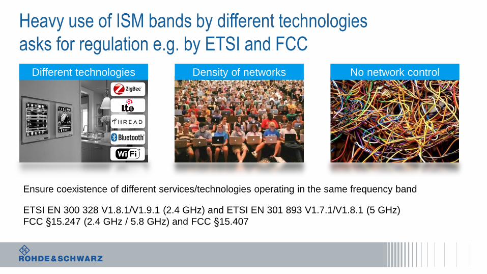
Heavy use of ISM bands by different technologies
asks for regulation e.g. by ETSI and FCC
Density of networks No network controlDifferent technologies
Ensure coexistence of different services/technologies operating in the same frequency band
ETSI EN 300 328 V1.8.1/V1.9.1 (2.4 GHz) and ETSI EN 301 893 V1.7.1/V1.8.1 (5 GHz)
FCC §15.247 (2.4 GHz / 5.8 GHz) and FCC §15.407

Example LoRa regulatory requirements FCC Part 15.247
Parameter Limit Specification
6 dB Tx bandwidth 500 kHz 15.247(a)(2)
Emission Output Power +30 dBm 15.247(b)(3)
Conducted Power Spectral Density +8 dBm / 3 kHz 15.247(e)
Emissions in Non-restricted bands - 30 dBc 15.247(d)
Emissions on restricted bands - 42.2 dBm 15.247(d)
20 dB Tx bandwidth < 500 kHz 15.247(a)(1)
COMPANY RESTRICTED
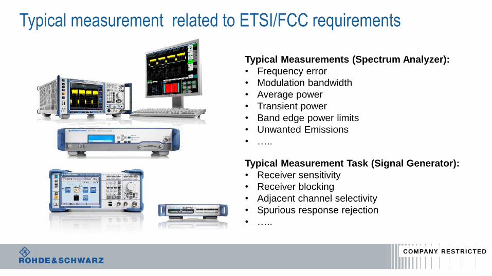
Typical measurement related to ETSI/FCC requirements
Typical Measurements (Spectrum Analyzer):
• Frequency error
• Modulation bandwidth
• Average power
• Transient power
• Band edge power limits
• Unwanted Emissions
• …..
Typical Measurement Task (Signal Generator):
• Receiver sensitivity
• Receiver blocking
• Adjacent channel selectivity
• Spurious response rejection
• …..
COMPANY RESTRICTED

R&S TS8997 Regulatory Test System for wireless devices
operating in 2.4 GHz and 5 GHz band• Covers all test cases required by the
standards ETSI EN 300 328 v1.8.1 and ETSI
EN 301 893 v1.7.1 to improve co-existence
of wireless technologies in ISM bands
• Special power measurement implemented in
OSP module
• Covers up to 4 channel MIMO
• Test software EMC32 with option –K97x
COMPANY RESTRICTED

Interference | Coexistence

2.4 GHz ISM Band – Smart Home Gateway
COMPANY RESTRICTED

Automated In-device interference analysis using R&S CMWrun
COMPANY RESTRICTED

Extremly low power consumption

It‘s all about connecting everything – wireless & cordless
Battery
capacity
5 Ah
0 Ah
10 Ah
15 Ah
101100 102 103 104 105
Day Week Month Year 10 years
High demand for cordless IoT devices using energy storage and/or harvesting technologies
• Battery is a cost factor: • Battery costs depend on
capacity
• Cost of battery replacement
• Design for replacement
• In some cases the battery lifetime defines the lifetime of the device
m3
P
Smart meter
Park sensor
Plant monitor
Container tracking
Phone
66
Watch Health monitor
Battery lifetime in hours
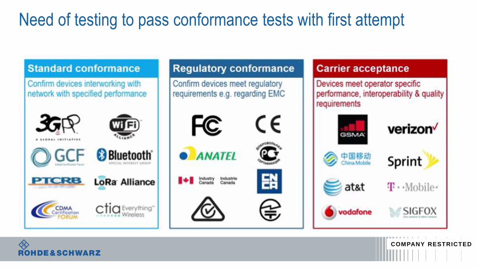
Need of testing to pass conformance tests with first attempt
COMPANY RESTRICTED

Overview of
emerging
technologies
Effectiveness of
production test
IoT testing aspects
and solutions
The wireless Internet of Things
Technologies & Challenges

Internet of Things need High Quality
Your brand
needs quality
Reliability
needs quality
User experience
needs quality

Mass Product Process: final test method
ı Only Go/NoGo test
ı Limited accuracy
ı Difficult to guarantee compatibility with other devices
ı Due to lack of measurements fault analysis and predictive analytics very difficult
ı No control of RF condition
Golden device method
GPS
WiFi
BLE
LTE
Go/NoGo test
GPS/GNSS/Beidou?
Worldwide?
802.11a/g/n/ac?
AP Compatibilities?
A golden BS?
How to test ?

Mass Product Process: final test method
GPS
WiFi
BLE
LTE
ı Go/NoGo with parametric and tolerance analysis
ı High accuracy
ı Capability test against wireless standards
ı Measurements = Analysis
ı Controlled RF condition with perfect isolation
Parametric method
Go/NoGo test

LPWA LoRa device mass production solution
http://www.semtech.com/wireless-rf/lora/LoRa-FAQs.pdf
Semtech1) recommends to test three important parameters in mass production:
Frequency tolerance
DUTSpectrum
Analyzer
e.g. R&S®FPS
Output power
DUTPower Sensor
e.g. R&S®NRP
Receiver sensitivity
DUTVector Signal
Generator
FSK/LoRa
e.g. R&S®SGT
1)
TestMode TestMode TestMode

Vector Network Analyzers for NFC antenna Verification
R&S®ZND vector network analyzer
R&S®CSNFC-B8 NFC Forum reference device
NFC Verification in production
ReferenceDevice DUT
• Fast measurement time <20 µs/point
• Fast data transfer time via LAN
(typ. 1ms for 200 measurement points)
• Simultaneous measurement of two DUTs with one
R&S ZND doubles the throughput rate in production

Mass Product Process: board level testing before assembly
Calibration Verification
Frequency
TX power
RX RSSI
Frequency offset
TX power, EVM, SEM,
ACLR
RX sensitivityGPS
WiFi
BLE
LTE

Parametric of wireless standards: example with 802.11ac
Constellation Diagram
Error Vector Magnitude
Spectrum Emission Mask
Spectrum Flatness
Power Frequency Error
ı Universal ARB generator
ı Fast measurements
ı Multi-evaluation
ı Same software from CMW family
Powerful measurement

Professional production line tester for cost reduction
Wireless Standards Production features
2G/3G/LTE etc
WiFi, BT/BLE, Zigbee
GPS/GNSS/Beidou
General purpose RF
Minimum footprint and
energy consumption
Close connection to test
fixture, less attenuation loss
and involved cross talking
Fanless for silent operation
Highest reliability due to
dustproof housing

Multi DUT in production line
Tester 2
Tester 1
Tester 4
Tester 3
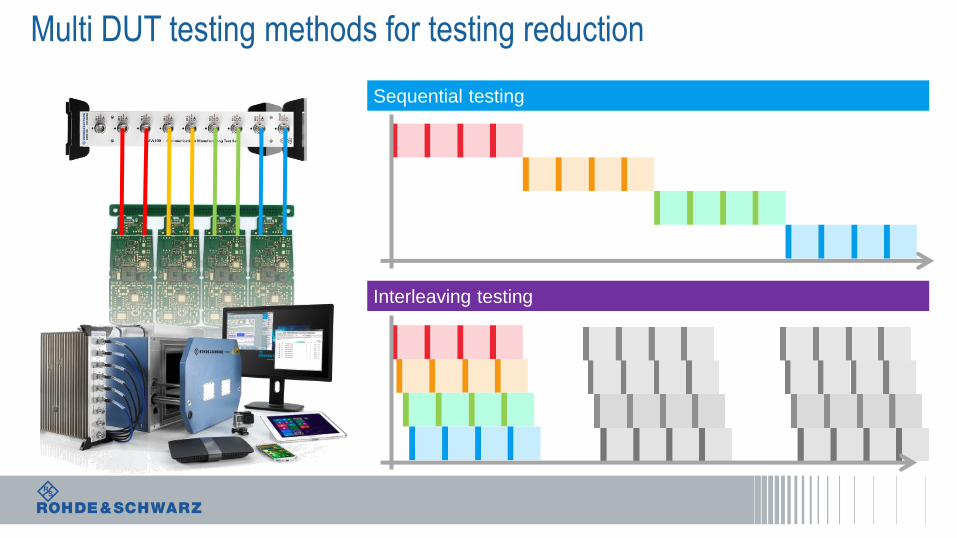
Multi DUT testing methods for testing reduction
Sequential testing
Interleaving testing

Future proof turnkey automation solution
ı Chipset vendor approved test plan/method
ı Statistic analysis of test results, live or remotely
ı Programming interface for other automation integration
CMWrun solution
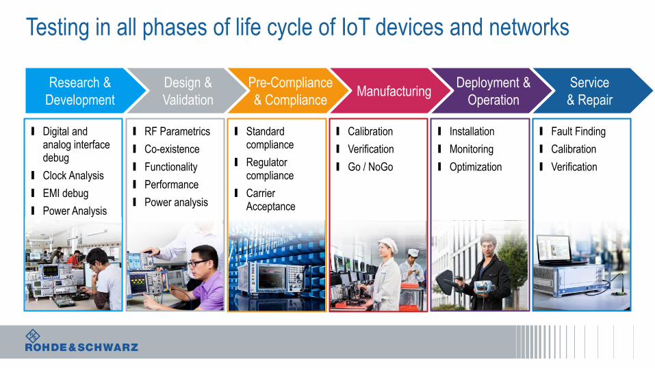
Service
& Repair
Testing in all phases of life cycle of IoT devices and networks
Deployment &
OperationManufacturing
Pre-Compliance
& Compliance
Design &
Validation
Research &
Development
I Digital and analog interface debug
I Clock Analysis
I EMI debug
I Power Analysis
I Installation
I Monitoring
I Optimization
I Calibration
I Verification
I Go / NoGo
I Standard compliance
I Regulator compliance
I Carrier Acceptance
I RF Parametrics
I Co-existence
I Functionality
I Performance
I Power analysis
I Fault Finding
I Calibration
I Verification

Your Partner in testing the Internet of Things