Embed Size (px)
Citation preview
IOT
POLY ENGINEERING2-16
January 26, 2010
Matching and Fill-in-the-Blank• Identifying drawing types
– Isometric, section, standard view, development, perspective, oblique, cut-away pictorial
• Reference planes– FRP, HRP, PRP
• Class standards– Line weight, line type, dimensioning, scales
QUIZ WEDNESDAY
Tech
nica
l Gra
phic
Com
mun
icati
on
IOT
POLY ENGINEERING2-10
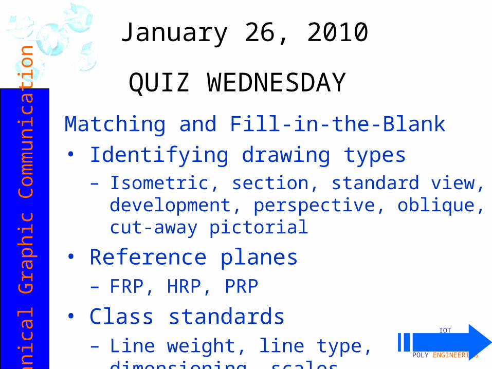
•So far, our standard 6 views are all visible using the three regular planes of projection
–Frontal Reference Plane–Horizontal Reference Plane–Profile Reference Plane
•Those views are drawn TRUE SIZE•However, inclines (slants) are not shown as true
size in standard views.
review AUXILIARY VIEWSTYPE 2
: M
ULT
I-V
IEW
IOT
POLY ENGINEERING2-10
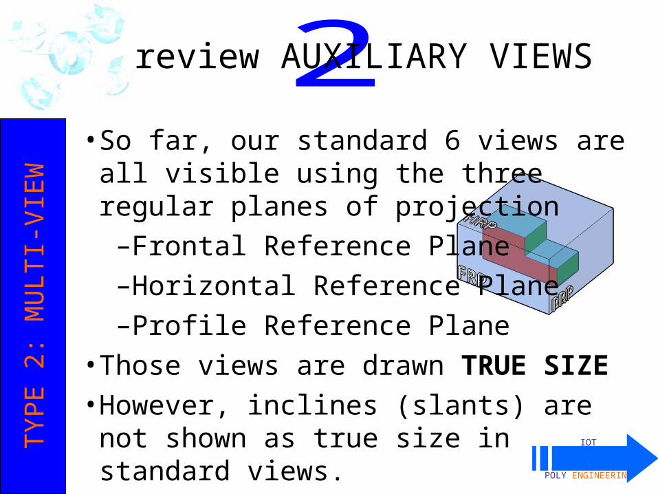
•Inclines (slants) are not shown as true size in standard views.
• Each square below represents 1”. What are the widths of the front view and right side views?
– 9” and 4”, respectively
reviewAUXILIARY VIEWSTYPE 2
: M
ULT
I-V
IEW
FRP
HRP
PRP
•Neither the front, top, or side view shows the true size and shape of the object’s inclined surface.
IOT
POLY ENGINEERING2-10
Review AUXILIARY VIEWSTYPE 2
: M
ULT
I-V
IEW
FRP
PRP
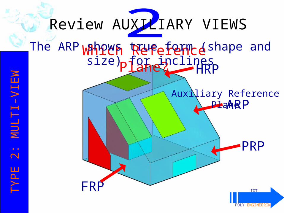
Which Reference Plane? HR
P
ARP
Auxiliary Reference Plane
The ARP shows true form (shape and size) for inclines
IOT
POLY ENGINEERING2-10
review ISOMETRICTYPE 3
: PIC
TO
RIA
L
Isometric Cube:
1) all lines equal length;
2) all faces equal area;
3) perimeter is a hexagon
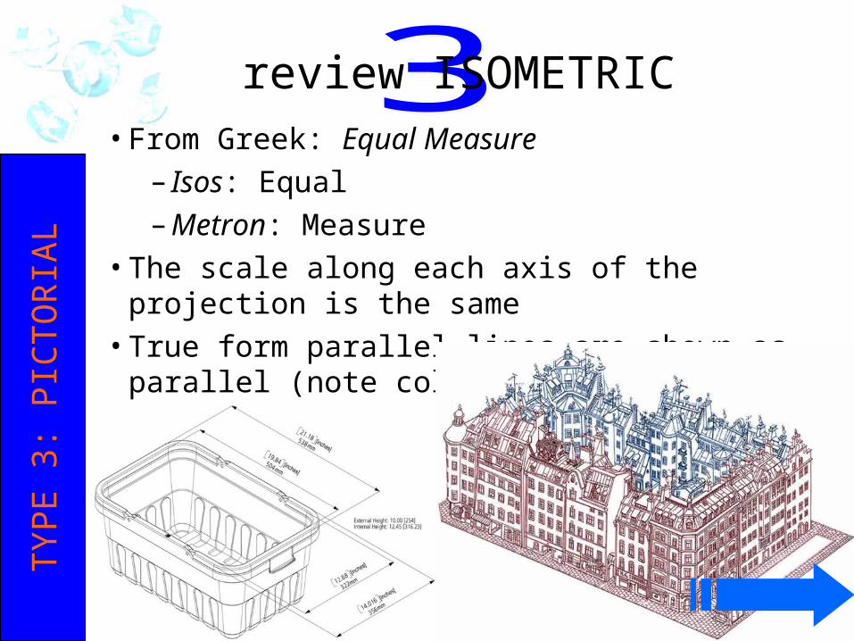
• From Greek: Equal Measure– Isos: Equal– Metron: Measure
• The scale along each axis of the projection is the same• True form parallel lines are shown as parallel (note colors
below)• All isometrics: simple construction
IOT
POLY ENGINEERING2-10
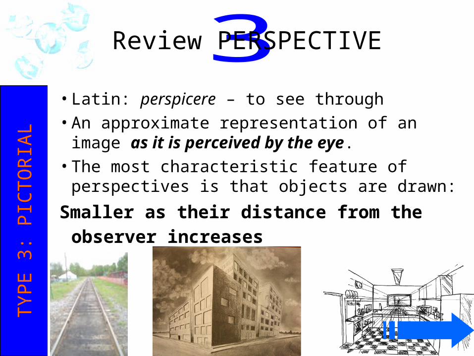
• Latin: perspicere – to see through• An approximate representation of an image as it is
perceived by the eye. • The most characteristic feature of perspectives is that
objects are drawn:
Smaller as their distance from the observer increases
Review PERSPECTIVETYPE 3
: PIC
TO
RIA
L
IOT
POLY ENGINEERING2-10
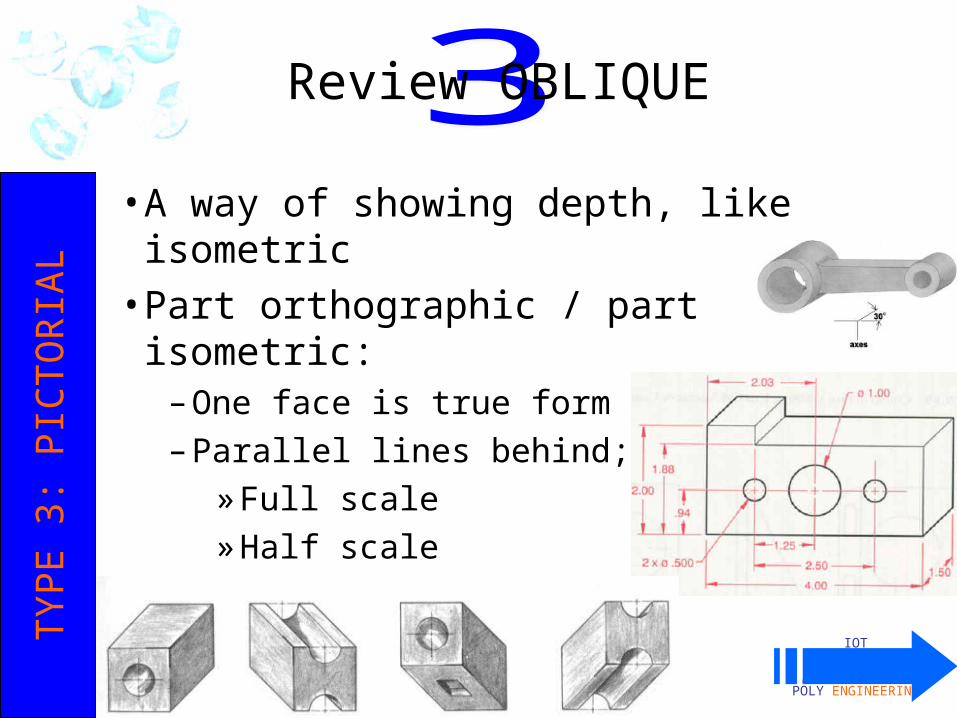
• A way of showing depth, like isometric• Part orthographic / part isometric:
– One face is true form– Parallel lines behind; either:
» Full scale» Half scale» Three-quarter scale
Review OBLIQUETYPE 3
: PIC
TO
RIA
L
IOT
POLY ENGINEERING2-10
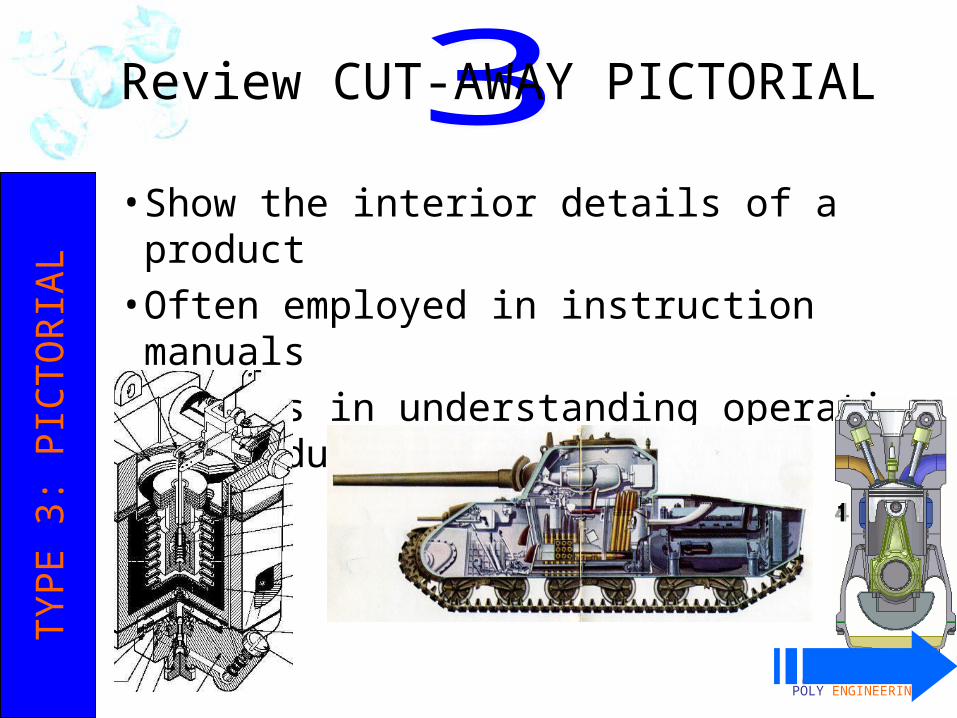
• Show the interior details of a product• Often employed in instruction manuals• Assists in understanding operation of product
Review CUT-AWAY PICTORIALTYPE 3
: PIC
TO
RIA
L
IOT
POLY ENGINEERING2-11
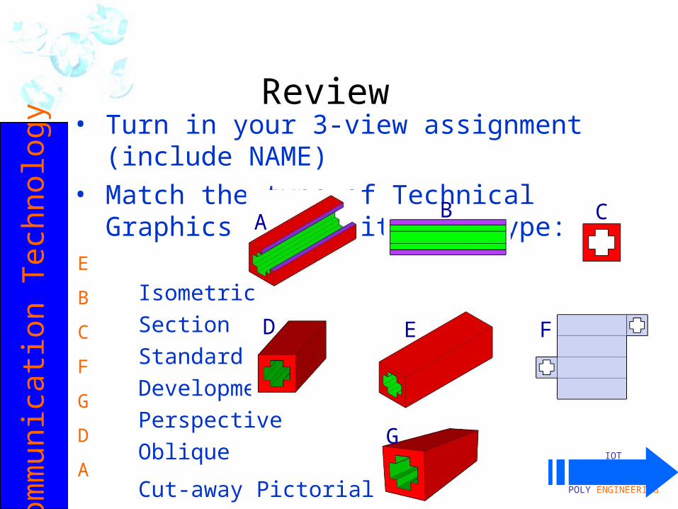
• Turn in your 3-view assignment (include NAME)• Match the type of Technical Graphics below with
its type:
Isometric Section Standard View Development Perspective Oblique
Cut-away Pictorial
Com
mun
icati
on
Tech
nolo
gy
Review
A B C
D E F
G
E
B
C
F
G
D
A
IOT
POLY ENGINEERING2-11
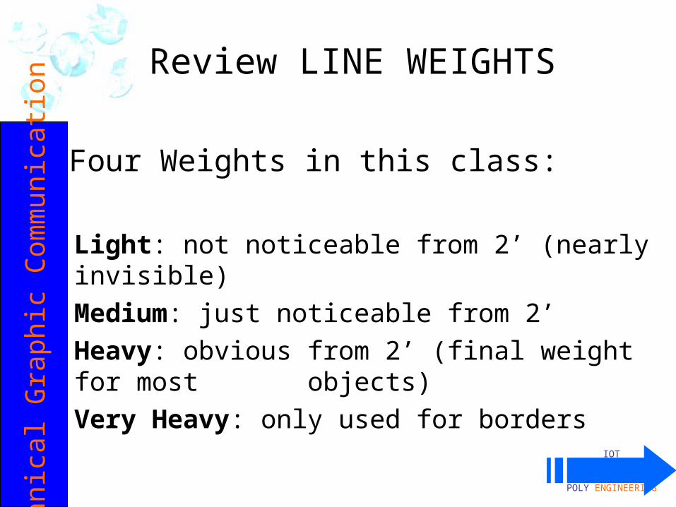
Four Weights in this class:
Light: not noticeable from 2’ (nearly invisible)
Medium: just noticeable from 2’Heavy: obvious from 2’ (final weight
for most objects)Very Heavy: only used for borders
Review LINE WEIGHTSTech
nic
al G
rap
hic
Com
munic
ati
on
IOT
POLY ENGINEERING2-11
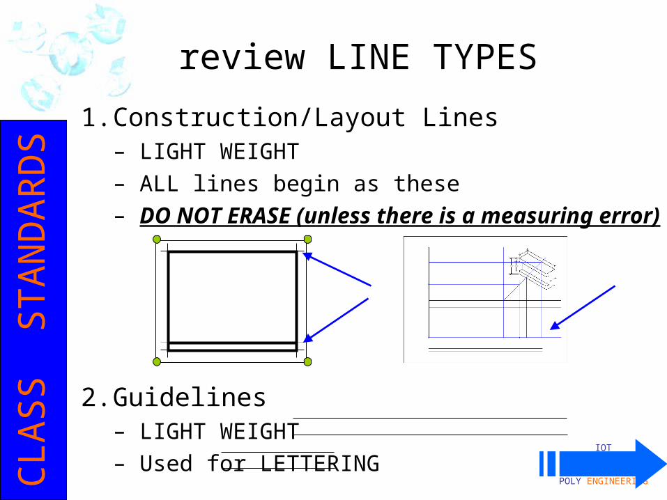
1. Construction/Layout Lines– LIGHT WEIGHT– ALL lines begin as these– DO NOT ERASE (unless there is a measuring error)
2. Guidelines– LIGHT WEIGHT– Used for LETTERING
review LINE TYPESC
LASS
STA
ND
AR
DS

IOT
POLY ENGINEERING2-11
3. Object Lines:– HEAVY WEIGHT– The final line type for most
objects
4. Hidden Lines:– HEAVY WEIGHT– Everything must be represented in each view, whether
or not it can be seen– Interior and exterior features are projected from view
to view in the same way– Parts not seen on the exterior of a view are drawn
with hidden lines – short DASHES
Review LINE TYPESC
LASS
STA
ND
AR
DS
IOT
POLY ENGINEERING2-11
• Objects to be drawn may be small – Nanotechnology machine parts, for example
• Objects to be drawn may be big– Buildings, bridges, airliners, oil rigs, trucks, cars
• Full Scale drawings will not always fit on a sheet of paper
• Scale down or scale up ½” = 1’-0” ¼” = 1’-0” 1” = 14’-0”
• Scale must be indicated in your title block• Architect’s Scale, Engineer’s Scale, Metric Scale
make scaling drawings simpler.
Review SCALESC
LASS
STA
ND
AR
DS
IOT
POLY ENGINEERING2-16
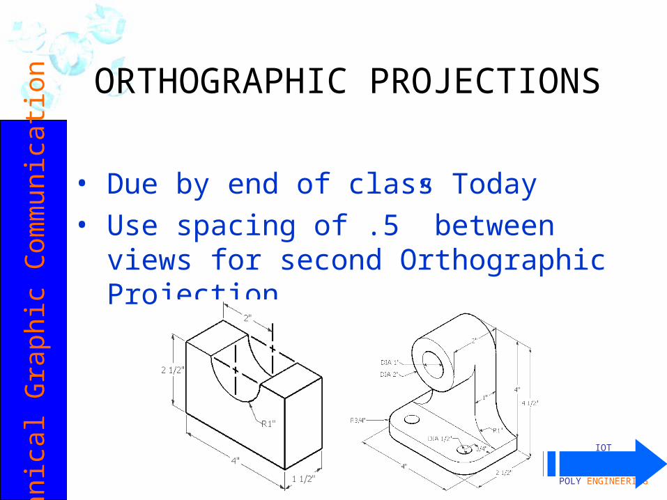
• Due by end of class Today• Use spacing of .5” between views for second
Orthographic Projection
ORTHOGRAPHIC PROJECTIONSTe
chni
cal G
raph
ic C
omm
unic
ation
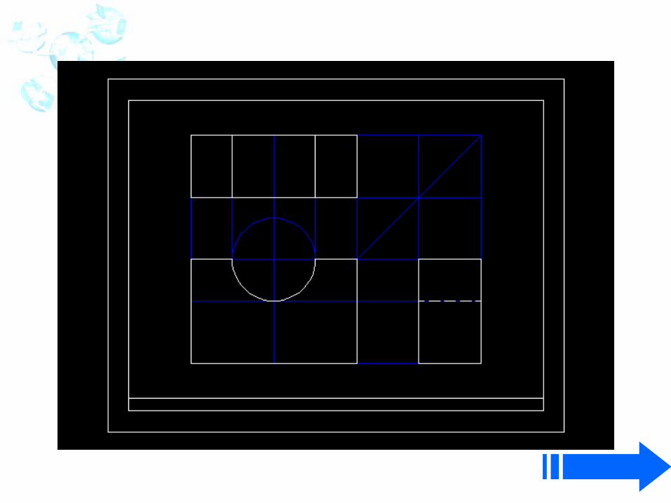

½”
1. Draw ½” border
5/16”
2. Draw a 5/16” title block
3. Add 2 LIGHT lettering guidelines, 1/16” from border lines
LETTER the title block information: BPI-IOT ORTHO PROJ 1 17 OCT 08 LAST, F FULL
SCALE
4. Add scale separator – Heavy Weight
1 ¾”
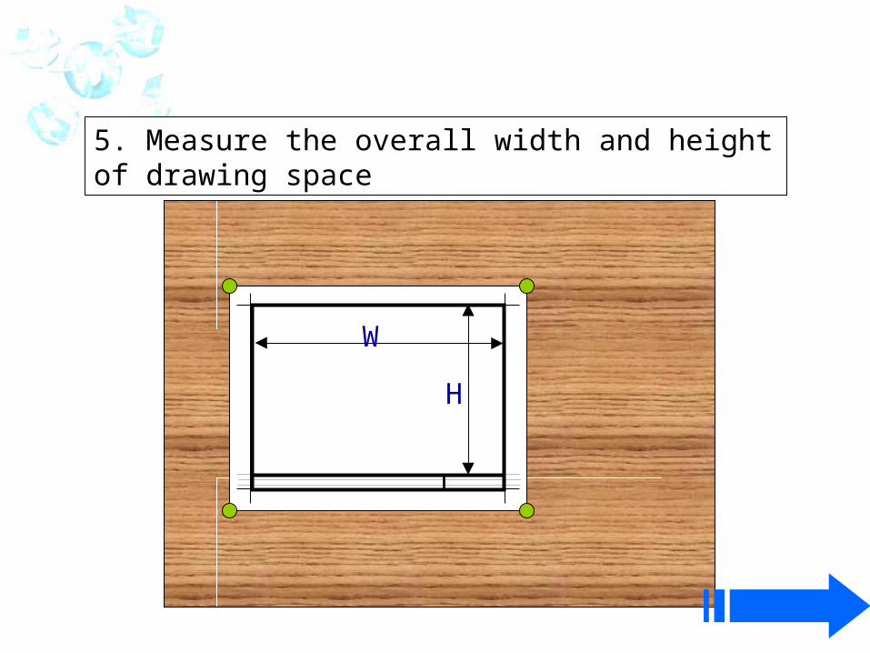
5. Measure the overall width and height of drawing space
W
H
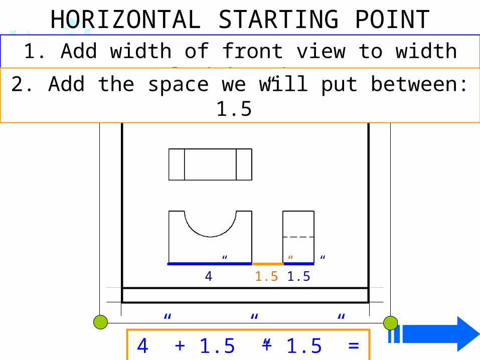
1. Add width of front view to width of right view.
1.5”
2. Add the space we will put between: 1.5”
4” 1.5”
4” + 1.5” + 1.5” = 7”
HORIZONTAL STARTING POINT
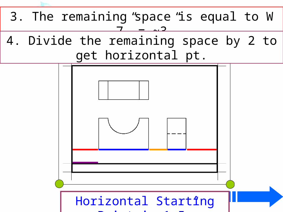
3. The remaining space is equal to W – 7” = ~3”.
4. Divide the remaining space by 2 to get horizontal pt.
Horizontal Starting Point is 1.5”
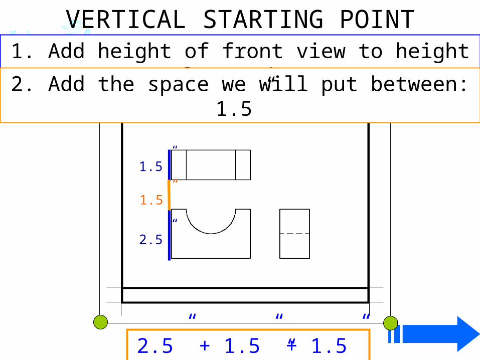
1. Add height of front view to height of top view.
1.5”
2. Add the space we will put between: 1.5”
2.5”
1.5”
2.5” + 1.5” + 1.5” = 5.5”
VERTICAL STARTING POINT
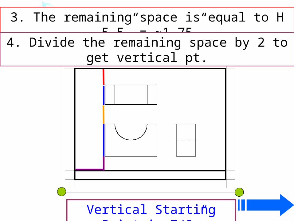
3. The remaining space is equal to H – 5.5” = ~1.75”.
4. Divide the remaining space by 2 to get vertical pt.
Vertical Starting Point is 7/8”
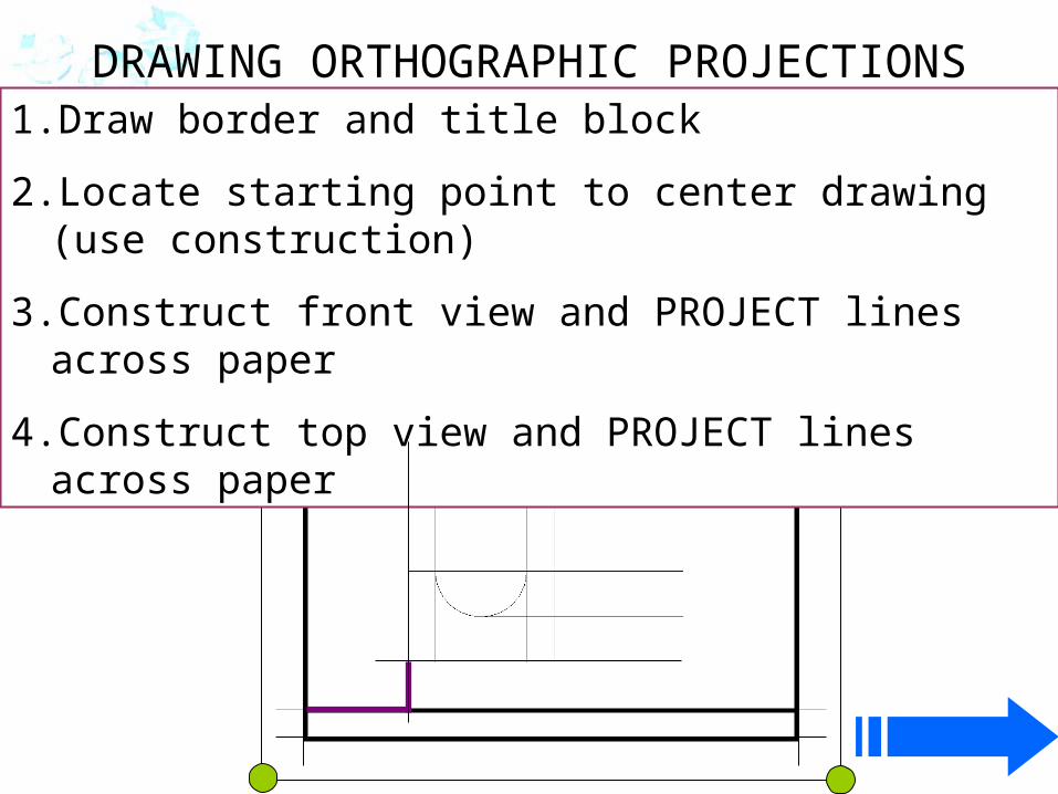
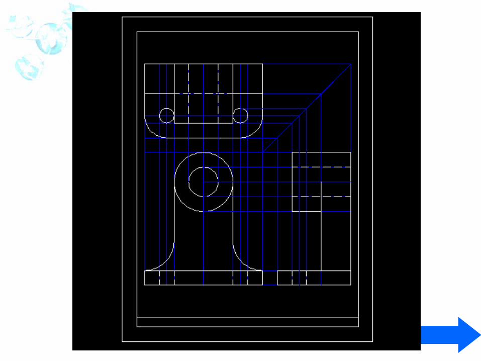
DRAWING ORTHOGRAPHIC PROJECTIONS1. Draw border and title block
2. Locate starting point to center drawing (use construction)
3. Construct front view and PROJECT lines across paper
4. Construct top view and PROJECT lines across paper
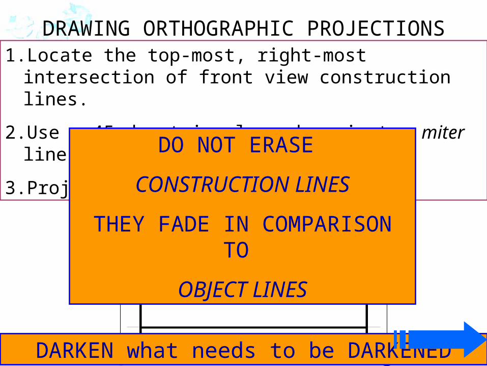
DRAWING ORTHOGRAPHIC PROJECTIONS1. Locate the top-most, right-most intersection of front view
construction lines.
2. Use a 45-deg triangle and project a miter line.
3. Project lines down for right view.
DARKEN what needs to be DARKENED
DO NOT ERASE
CONSTRUCTION LINES
THEY FADE IN COMPARISON TO
OBJECT LINES