Embed Size (px)
Citation preview

Ionic Electrets: Electrostatic Charging of Surfaces byTransferring Mobile Ions upon Contact
Logan S. McCarty, Adam Winkleman, and George M. Whitesides*
Contribution from the Department of Chemistry and Chemical Biology, HarVard UniVersity, 12Oxford Street, Cambridge, Massachusetts 02138
Received October 11, 2006; E-mail: [email protected]
Abstract: This paper describes the fabrication and characterization of ionic electretssmaterials that beara long-lived electrostatic charge because of an imbalance between the number of cationic and anioniccharges in the material. Crosslinked polystyrene microspheres that contain covalently bound ions and mobilecounterions transfer some of their mobile ions in air, in the absence of bulk liquid, to another material uponcontact. According to the ion-transfer model of contact electrification, this selective transfer of mobile ionsyields microspheres that have a net electrostatic charge. A tool that operates on the principle of electrostaticinduction measures the charge on individual microspheres (50-450 µm in diameter). Microspheres with avariety of covalently bound ionic functional groups (tetraalkylammonium, alkyltriphenylphosphonium,alkylsulfonate, and arylsulfonate) acquire charges consistent with this ion-transfer mechanism. The chargeon a microsphere is proportional to its surface area (ca. 1 elementary charge per 2000 nm2) and close tothe theoretical limit imposed by the dielectric breakdown of air. The charge density in an atmosphere ofSF6 is more than twice that in an atmosphere of N2. These observations suggest that the charge densityof these ionic electret microspheres is limited by the dielectric breakdown of the surrounding gas.Functionalizing the surfaces of glass or silicon with covalently bound ions and mobile counterions generatesionic electrets from these inorganic substrates. Soft lithography can pattern charge on a planar siliconsurface (with oxide) and on the surface of 250-µm glass microspheres.
Introduction
This paper describes the fabrication and characterization ofionic electretssmaterials that bear a long-lived electrostaticcharge because of an imbalance between the number of cationicand anionic charges in the material. By introducing ionic groupsinto a solid matrix, we can predictably and reproducibly createionic electrets; these ionic groups must have one type of chargecovalently bound and the other mobile. This method works wellwith crosslinked polystyrene, glass, and silicon (i.e., with thesilicon dioxide layer on the surface of silicon). We charge theseelectrets by contact electrificationsthe transfer of charge fromone surface to another upon contactsusing a strategy based onthe ion-transfer model hypothesized by Diaz and co-workers.1-3
Using a tool that operates on the principle of electrostaticinduction, we measure the charge on these materials, anddemonstrate that the ion-transfer model correctly predicts thesign of their charge. The magnitude of the limiting charge on aspherical ionic electret is proportional to its surface area; thedielectric breakdown of air appears to limit the amount ofcharge. We also pattern charge on the surface of planar andspherical ionic electrets.
Chemists generally assume that bulk matter is electricallyneutral; ionic materials, in particular, are assumed to have anequal number of cationic and anionic charges. This principle
of electroneutrality is taught starting at the beginning ofintroductory chemistry textbooks.4 We challenge this assumptionby preparing various materials with covalently bound ions andmobile counterions that develop a macroscopic electrostaticcharge upon contact with another surface. This charge arises asa result of an imbalance between the number of cationic andanionic charges in (or on) the material that occurs, on contact,when a small number of mobile ions transfer from one surfaceto the other.
Similar materials find wide application in photocopying andlaser printing, and the current understanding of the ion-transfermechanism of contact electrification comes from studies oftoners used in photocopiers.5 Because contact electrification isa simple and inexpensive technique for creating charged objects,an improved understanding of this phenomenon could lead towider use of electrostatically charged materials and to the abilityto predict, engineer, and pattern regions of net electrostaticcharge. Electrostatically charged materials are otherwise pre-pared by techniques such as bombardment with an electron-beam or ion-beam or by exposure to a corona from a high-voltage electrode.6 Improved knowledge of the factors thatdetermine contact electrification could also aid in the preventionand control of unwanted charging of materials.7,8
(1) Diaz, A. F.J. Adhes.1998, 67, 111-122.(2) Diaz, A. F.; Fenzel-Alexander, D.Langmuir1993, 9, 1009-1015.(3) Diaz, A. F.; Guay, J.IBM J. Res. DeV. 1993, 37, 249-259.
(4) See, for example: Petrucci, R. M.; Harwood, W. S.; Herring, F. G.; Madura,J. D. General Chemistry: Principles and Modern Applications; PearsonPrentice Hall: Upper Saddle River, NJ, 2007.
(5) Pai, D. M.; Springett, B. E.ReV. Mod. Phys.1993, 65, 163-211.
Published on Web 02/21/2007
10.1021/ja067301e CCC: $37.00 © 2007 American Chemical Society J. AM. CHEM. SOC. 2007 , 129, 4075-4088 9 4075

Background
Properties and Uses of Electrets.The termelectretorigi-nated in the late 19th century to describe a material that is anelectrostatic analogue of a permanent magnet. Although poledelectrets have macroscopic electric dipole moments, and areanalogous in some sense to permanent magnets, space-chargeelectrets, which bear a net electrostatic charge, have no magneticanalogue. Classical wax electrets, formed by cooling andsolidifying molten wax in a strong electric field, have amacroscopic electric dipole moment due to a net orientation ofmolecular dipoles; similarly, poly(vinylidine difluoride), PVDF,can be poled by subjecting it to a strong electric field above itsglass transition temperature (Tg) and cooling it to belowTg inthat field.6 Space-charge electrets are typically formed by addingcharge onto the surface or into the bulk of a material with anelectron-beam, an ion-beam, corona discharge from a high-voltage electrode, or direct contact with a charged electrode.These techniques can also pattern charge in an electret.9-11
Electronic or ionic charges in space-charge electrets may remainon the surface or deeper in the bulk of the material.
Electrets are applied broadly in technologies that make apowder or liquid adhere selectively to another object. Aftercharging the powder, the target object, or both, electrostaticforces guide the powder to coat certain regions of the target.One well-known technology that uses charge-guided patterningis xerography, in which a corona charges a photoconductiveimaging drum, light depletes the charge in certain regions, andtoner powder (usually charged by contact electrification) adheresspecifically to the regions of charge on the drum.5 Electrostaticseparation technologies can separate coal from various impuri-ties, and separate powders composed of different types of plasticfor recycling.12,13Electrostatic powder coating and electrostaticspray painting coat large objects with a uniform layer of plasticpowder or paint;14,15similar techniques apply powdered flavor-ings and salt to potato chips16 and popcorn.17 (Our recentdemonstration of electrostatic self-assembly of chemicallymodified polystyrene microspheres18 is similar to electrostaticpowder coating, though on a much smaller size scale.) Otherapplications of electrets include electret microphones, in whichthe acoustical vibration of a thin electret membrane inducesvoltage fluctuations between two electrodes,6 and Van de Graaffgenerators, which rely on the storage and transport of chargeon an electrically insulating belt.19
There are many instances in which electrostatic charging mustbe avoided. Helicopter blades (and helicopters) develop sub-
stantial electrical charge when moving through air; this chargecan be lethal if a person approaches an ungrounded helicopterthat is near the ground.20 The flow of liquids or powders throughpipes often leads to electrostatic charging. This charging canbe a substantial hazard with pharmaceutical powders21 orhydrocarbon fuels.7,22 The charge accumulated on a person’sbody in a low-humidity environment is sufficient to destroysensitive electronic equipment.8,23,24
The Ion-Transfer Model of Contact Electrification. Whentwo solid surfaces are brought into contact and separated (withor without rubbing), charge is often transferred from one surfaceto the other in a process known as “contact electrification” or“tribocharging”.25,26 Despite its economic significance (bothbeneficial and harmful), contact electrification remains poorlyunderstood, especially at the molecular or atomic level. Eventhe most fundamental question of whether the charge carrier isan electron or an ion is still under debate.3,25-37 Nearly allmaterials (metals, semiconductors, and insulators) undergocontact electrification under a wide range of environmentalconditions; it is likely that different mechanisms of electrificationdominate in different circumstances. There are two kinds ofmaterials for which there is general agreement on the mechanismof contact electrification: (i) contact between two differentmetals results in the transfer of electrons owing to the differencein work functions of the metals,38 and (ii) any contact with amaterial that has covalently bound ions and mobile counterionsresults in the transfer of some of the mobile ions to the contactedsurface.1 Diaz and co-workers investigated the latter processand developed the ion-transfer model of contact electrification,shown schematically in Figure 1.2,3
The ion-transfer model makes two qualitative predictions.First, the sign of charge acquired by the ionic material (theionomer) should be the same as the sign of the covalently boundion. Second, the mobile ion should be observed on the othersurface after contact. Diaz confirmed both predictions using
(6) Electrets; Sessler, G. M., Gerhard-Multhaupt, R., Eds.; Laplacian Press:Morgan Hill, CA, 1998.
(7) Gibson, N.J. Electrostat.1997, 40-41, 21-30.(8) Greason, W. D.IEEE Trans. Ind. Appl.1987, 23, 205-216.(9) Jacobs, H. O.; Whitesides, G. M.Science2001, 291, 1763-1766.
(10) Mikihiko, K.; Norio, S.; Takehiro, D.; Hiroshi, F.; Takeshi, K.; Mitsuru,E. Proc. SPIE-Int. Soc. Opt. Eng.2001, 4334, 263-270.
(11) Rezek, B.; Stuchlik, J.; Kocka, J.; Stemmer, A.J. Non-Cryst. Solids2005,351, 3127-3131.
(12) Kwetkus, B. A.Particulate Sci. Technol.1998, 16, 55-68.(13) Higashiyama, Y.; Asano, K.Particulate Sci. Technol.1998, 16, 77-90.(14) Richart, D. S. InKirk-Othmer Encyclopedia of Chemical Technology, 4th
ed.; Kroschwitz, J. I., Howe-Grant, M., Eds.; Wiley: New York, 1992;Vol. 6, pp 635-661.
(15) Bailey, A. G.J. Electrostat.1998, 45, 85-120.(16) Ratanatriwong, P.; Barringer, S.; Delwiche, J.J. Food Sci.2003, 68, 1542-
1547.(17) Miller, M. J.; Barringer, S. A.J. Food Sci.2002, 67, 198-201.(18) McCarty, L. S.; Winkleman, A.; Whitesides, G. M.Angew. Chem., Int.
Ed. 2006, 46, 206-209.(19) Halliday, D.; Resnick, R.; Walker, J.Fundamentals of Physics; J. Wiley
& Sons: Hoboken, NJ, 2005.
(20) Felici, N.; Larigaldie, S.J. Electrostat.1980, 9, 59-70.(21) Bailey, A. G.Powder Technol.1984, 37, 71-85.(22) Morrison, I. D.Colloids Surf. A1993, 71, 1-37.(23) Davies, D. K.J. Electrostat.1985, 16, 329-342.(24) Crockett, R. G. M.; Hughes, J. F.; Pude, J. R. G.; Sno, H. M.J. Electrostat.
1985, 16, 343-352.(25) Harper, W. R.Contact and Frictional Electrification; Laplacian Press:
Morgan Hill, CA, 1998.(26) Lowell, J.; Rose-Innes, A. C.AdV. Phys.1980, 29, 947-1023.(27) Medley, J. A.Nature1953, 171, 1077-1077.(28) Davies, D. K.J. Phys. D: Appl. Phys.1969, 2, 1533-1537.(29) Lee, L. H.Photog. Sci. Eng.1978, 22, 228-231.(30) Duke, C. B.; Fabish, T. J.J. Appl. Phys.1978, 49, 315-321.(31) Gibson, H. W.Polymer1984, 25, 3-27.(32) Anderson, J. H.J. Imaging Sci.1989, 33, 200-203.(33) Sakaguchi, M.; Shimada, S.; Kashiwabara, H.Macromolecules1990, 23,
5038-5040.(34) Horn, R. G.; Smith, D. T.; Grabbe, A.Nature1993, 366, 442-443.(35) Clint, J. H.; Dunstan, T. S.Europhys. Lett.2001, 54, 320-322.(36) Hoshino, K.; Ohoka, H.; Kokado, H.; Kitamura, T.Macromol. Chem. Phys.
2001, 202, 367-374.(37) Grzybowski, B. A.; Fialkowski, M.; Wiles, J. A.J. Phys. Chem. B2005,
109, 20511-20515.(38) Harper, W. R.Proc. R. Soc. London, Ser. A1951, 205, 83-103.
Figure 1. Schematic illustration of the ion-transfer mechanism of contactelectrification.
A R T I C L E S McCarty et al.
4076 J. AM. CHEM. SOC. 9 VOL. 129, NO. 13, 2007

materials that were made by melt-mixing a styrene-butylmethacrylate random copolymer with various ionomers, suchas poly(N-methylvinylpyridinium toluenesulfonate). These ma-terials served as models for xerographic toners;39 they weremilled and sorted by size to yield ca. 10-µm particles. Diazand co-workers measured the contact electrification of thesepowders using a “blow-off” Faraday cage commonly used inthe photocopying industry,40 and found that the sign of chargeagreed with the predictions of the ion-transfer model. He usedX-ray photoelectron spectroscopy to demonstrate transfer of themobile ion but not the covalently bound ion following contact.41
Other researchers also observed that ion-transfer accompaniedthe contact electrification of polymers doped with variousorganic salts.42,43
The ion-transfer model, in its most basic form, does not makeany predictions about the magnitude of charge expected fromcontact electrification. There are physical limitations on theamount of charge that can be stored on an electret: when theelectric field at the surface of the electret exceeds certain limits,dielectric breakdown of the surrounding gas, or field emissionin a vacuum, will partially discharge the electret.6,25,44Previousstudies of the magnitude of charge attained by contact electri-fication had several limitations. The “blow-off” Faraday cagemeasures the charge per unitmassof bulk powder, while thecharge per unitareadetermines the electric field at the surface.Melt-mixed polymer powders, though relevant as a model fortoner, likely exhibit phase segregation, an unknown surfacecomposition, and uncontrolled surface morphology.
Experimental Design
We had five experimental objectives. (i) We wanted to testthe usefulness of the ion-transfer model of contact electrificationin the design of materials that develop a certain sign of chargeupon contact. Chloromethylated crosslinked polystyrene mi-crospheres (Merrifield resin) offered a versatile matrix on whichwe could generate various ionic functional groups. Upon contactwith another surface, microspheres with bound cations becamepositively charged, while microspheres with bound anionsbecame negatively charged. (ii) We wanted to measure thecharge per unit area of these ionic electret materials. Using atool specifically developed for this purpose that can measurethe electrostatic charge on single microspheres, we measuredcharge as a function of surface area for microspheres withdiameters of 50-450 µm. (iii) We wanted to determine themaximum charge that an electret can acquire through contactelectrification and identify the factors that influence thismaximum charge. By comparing the maximum charge ofelectret microspheres containing various ionic groups undervarious conditions (different humidity, various gases), we foundthat the dielectric breakdown of air or the surrounding gas limitsthe maximum stable charge on a spherical electret. (iv) Wewanted to make ionic electrets from materials other thanpolymers. The surfaces of glass and silicon, functionalized with
silanes containing covalently bound ions and mobile counterions,acquired charge upon contact, in accord with the ion-transfermodel. (v) We wanted to demonstrate that ionic electrets couldbe prepared with a pattern of charge. Using the techniques ofsoft lithography,45 we patterned charge on planar silicon surfacesand on glass microspheres and imaged the patterns of chargeusing Kelvin probe force microscopy (KFM)46-48 and electro-static self-assembly.18
Results and Discussion
Fabrication of Ionic Electrets from Polystyrene Micro-spheres.Scheme 1 shows our approach to the functionalizationof monodisperse crosslinked polystyrene microspheres of vari-ous sizes. After chloromethylating the polystyrene spheres,49
we introduced various ionic functional groups, such as tet-raalkylammonium (1), sulfonate (2), and alkyltriphenylphos-phonium (3). We also used a sulfonated azobenzene moiety(4).18 The degree of functional group substitution was suf-ficiently low (∼5 to 10% of the styrene residues) that thesepolystyrene resins remained hydrophobic: they did not swellin water (unlike typical ion-exchange resins). Because there isa suggestion in the literature that water might play a role in theion-transfer mechanism of contact electrification,50 we preparedderivatives with both hydrophilic counterions (sodium orchloride) and hydrophobic counterions (tetraphenylphosphoniumor tetraphenylborate) using ion exchange.
A Tool for Measuring the Charge on Ionic ElectretMicrospheres.We designed and built a tool that can measurethe electrostatic charge on single microspheres. Figure 2a showsthe basic design of the tool; Figure S5 in the SupportingInformation has a photgraph. This tool consists of fourconcentric cylinders: a central polyethylene tube surroundedby two aluminum cylinders (electrically insulated from eachother), all enclosed inside a grounded steel cylinder that shieldsthe device from stray electric fields. A shielded triaxial cableconnects the two aluminum cylinders to an electrometer. Oneend of the polyethylene tube is connected to house vacuum,while the other end is open to the atmosphere. When the openend of this tube is brought near a charged bead, the flow of airdraws the bead through the polyethylene tube.
The electrometer, in charge-measurement mode, acts as anintegrating ammeter: it maintains the two aluminum cylindersat the same electrical potential and measures the total flow ofcharge (the time integral of the current) between them. Theelectrometer averages this charge over a period of 1/60 of asecond and records the average charge. Because there are nofree charges in the space between the cylinders, the potentialin that region is described by Laplace’s equation. The constantelectrostatic potential on the boundary yields a unique solu-tion: a constant electrostatic potential throughout the regionbetween the cylinders. This constant potential means that thereis no electric field in the space between the cylinders, so thetotal flux of the electric field through a cylindrical Gaussian
(39) Macholdt, H. T.; Sieber, A.J. Imaging Technol.1988, 14, 89-93.(40) Schein, L. B.Electrophotography and DeVelopment Physics; Laplacian
Press: Morgan Hill, CA, 1996.(41) Diaz, A. F.; Wollmann, D.; Dreblow, D.Chem. Mater.1991, 3, 997-999.(42) Mizes, H. A.; Conwell, E. M.; Salamida, D. P.Appl. Phys. Lett.1990, 56,
1597-1599.(43) Law, K. Y.; Tarnawskyj, I. W.; Salamida, D.; Debies, T.Chem. Mater.
1995, 7, 2090-2095.(44) Meek, J. M.; Craggs, J. D.Electrical Breakdown of Gases; Clarendon
Press: Oxford, 1953.
(45) Xia, Y. N.; Whitesides, G. M.Angew. Chem., Int. Ed.1998, 37, 551-575.(46) Martin, Y.; Abraham, D. W.; Wickramasinghe, H. K.Appl. Phys. Lett.
1988, 52, 1103-1105.(47) Nonnenmacher, M.; Oboyle, M. P.; Wickramasinghe, H. K.Appl. Phys.
Lett. 1991, 58, 2921-2923.(48) Jacobs, H. O.; Knapp, H. F.; Stemmer, A.ReV. Sci. Instrum.1999, 70,
1756-1760.(49) Itsuno, S.; Uchikoshi, K.; Ito, K.J. Am. Chem. Soc.1990, 112, 8187-
8188.(50) Pence, S.; Novotny, V. J.; Diaz, A. F.Langmuir1994, 10, 592-596.
Electrostatic Charging of Surfaces A R T I C L E S
J. AM. CHEM. SOC. 9 VOL. 129, NO. 13, 2007 4077

surface constructed between the inner and outer cylinders mustbe zero. By Gauss’s Law, the total charge on the inner cylinderand any of its contents (e.g., a charged bead) will always bezero. When a positively charged bead enters the centralaluminum cylinder, electrons flow from the outer cylinder tothe inner cylinder (Figure 2b) in order that thetotal charge onthe inner cylinder plus the bead remains equal to zero. Theamount of charge that flows through the electrometer is equalto the charge on the bead. When the bead exits the innercylinder, these induced charges flow back through the elec-trometer. The device makes two measurements of charge foreach bead: first, when the bead enters the inner cylinder, andsecond, when the bead exits the cylinder.
Ideally, a graph of charge as a function of time for a singlebead should yield a symmetric square-shaped peak. Figure 3ashows an example of an actual peak. The internal averaging ofthe electrometer results in some interpolated data points, suchas the one marked with an asterisk in the figure. The width ofthe square peak indicates the length of time (∼60 microseconds)required for the bead to traverse the central aluminum cylinder(a distance of 1 meter). The charge on the bead when it entersthe device (the leading-edge charge) is equal to the differencebetween the top of the peak and the initial baseline, while thecharge on the bead when it exits the device (the lagging-edgecharge) is equal to the difference between the top of the peakand the final baseline. Note that the baseline shifts: the leading-edge charge is not equal to the lagging-edge charge. Apparently,the bead emerges with a different charge than it had when itentered. We believe that the bead collides with the walls of thepolyethylene tube as it travels through the device, and thesecollisions result in contact electrification reflecting transfer ofcharge between the bead and the tube. The flow of air throughthe device is turbulent (average velocity∼70 m/s, for a Reynoldsnumber of∼6000), and the tube is not perfectly straight, so
such collisions are likely. As we shall discuss later, however,this baseline shift is not statistically significant.
Measuring the flow of charge between two concentriccylinders, rather than measuring the charge induced on oneelectrode relative to ground, helps to minimize the inevitablenoise and charge fluctuations of the ground. The digitalelectrometer has a precision of 10 fC (∼60 000 elementarycharges); the baseline rms noise (peak-to-peak) of our devicewas less than 20 fC. The smallest beads that we measured (50-µm diameter) had charges that were ca. 40 times the rms noise.
We scrutinized any peaks that lay more than three standarddeviations from the mean for a given sample of beads and wouldexclude a peak from our analysis of the data in two situations.Sometimes, more than one bead would pass through the deviceat the same time. We usually noticed these events during thecollection of data, and the resulting peaks had multiple plateaus,as shown in Figure 3b. These peaks were higher than the otherpeaks, and had a total charge that was a whole-number multipleof the charge on a single bead. At other times, a bead wouldpass through the device so rapidly that the electrometer, withits internal averaging, would not capture the full charge of thebead. Since a very narrow square peak, upon averaging, yieldsa much lower triangular peak, these events would lead to peakswith only a single data point at the apex, and an unusually lowcharge. Using both of these criteria, we rejected about 5% ofthe peaks collected in any given experiment. We retained anystatistical outliers that did not have an obviously erroneous peakshape.
Figure 4a shows an example of the raw output from theelectrometer for measurements of charge of 41 positivelycharged, 200-µm-diameter beads with alkyltriphenylphospho-nium functionality (3). We eliminated one peak from the databecause it had an unusually low charge and only a single datapoint at its apex. The peaks have various widths, indicating that
Scheme 1. Synthetic Scheme for the Functionalization of Crosslinked Polystyrene to Yield Ionic Electrets with Various Ionic FunctionalGroupsa
a The Experimental Section provides experimental details.
A R T I C L E S McCarty et al.
4078 J. AM. CHEM. SOC. 9 VOL. 129, NO. 13, 2007

beads traverse the device at different average speeds. Theturbulent flow of air and random collisions between the beadand the tube are consistent with this observation. The width ofeach peak is not correlated with the charge measured for thatbead. The heights of the peaks appear to be similar. Bothbaseline shift (bead-to-bead) and overall baseline drift areevident.
A simple peak-finding algorithm calculated the leading-edgecharge and the lagging-edge charge for each peak. Figure 4 partsb, c, and d show histograms of the leading-edge charge, thelagging-edge charge, and the average charge, respectively, forthe 41 beads measured in Figure 4a. The differences betweenthe mean charges determined by these three methods are notstatistically significant, as confirmed by pairedt-tests. Forconsistency in comparing different experiments, we used onlythe leading-edge charge, which better represents the charge onthe bead when it enters the device and is more informative, webelieve, than the other measures of charge. We presenthistograms to highlight any statistical outliers: in particular,we wish to draw attention to any beads that had a different signof charge from the other beads in a sample. (Later in this paper,we will provide evidence that the broad distributions of chargeseen in these histograms indicate an actual distribution of
charges on the beads, and are not mere artifacts of theuncertainty of our measuring device.)
Figure 5a shows measurements of the reproducibility of ourcharge-measuring device using 200-µm-diameter beads havingimmobilized tetraalkylammonium cations and mobile anions (1).Measurements of three different samples of these beads on asingle day yielded mean charges that were statistically indis-tinguishable. Measurements made on three other days, over aspan of 7 months, under various ambient conditions of tem-perature and humidity, had statistically significant differences.When we sought quantitative comparisons between differentbatches of beads, we measured the various beads on a singleday to ensure that these comparisons would be statisticallymeaningful. Measurements made on different days are repro-ducible to within about one standard deviation (ca. 25% of themean charge). We show later that differences in the ambienthumidity can explain the variations in the amounts of chargeobserved on different days.
Following the procedure used in our previous communica-tion,18 we charged the electret beads by placing them in analuminum dish and manually agitating the dish at a frequencyof ∼3 Hz for ∼1 min before making the measurements ofcharge. (We later found that extensive agitation was notnecessary. As we discuss in the next paragraph, the brief contactbetween the beads and the polyethylene tube inside the charge-measuring device imparted substantial charges to these beads.)
Figure 2. (a) Schematic illustration of the apparatus used for measuringthe charge on individual microspheres; (b) schematic of the process by whichthe apparatus measures the charge on a microsphere.
Figure 3. (a) An example of a peak resulting from the passage of a singlepositively charged bead through the apparatus. The leading-edge charge,lagging-edge charge, and baseline shift are indicated. The datum indicatedwith an asterisk (/) is an artifact of the internal averaging used by theelectrometer. (b) An example of a peak resulting from the passage of twopositively charged beads together through the apparatus. Such a peak wouldbe excluded from the data analysis. (c) An example of a peak with only asingle datum at its apex that resulted from the very rapid passage of a singlepositively charged bead through the apparatus. The mean and standarddeviation of other beads in the same sample is indicated; the observed peakfalls more than three standard deviations below the mean. Such a peak wouldalso be excluded from the analysis.
Electrostatic Charging of Surfaces A R T I C L E S
J. AM. CHEM. SOC. 9 VOL. 129, NO. 13, 2007 4079

Figure 5b compares the results of using various other materialsfor the contact electrification of these beads. The beads wereagitated in a glass vial, or rolled between two sheets of polymerfilmspolyethylene (PE), poly(hexamethylene adipamide) (Nylon-6,6), or poly(tetrafluoroethylene) (PTFE)sbefore making themeasurements of charge. Although the differences between someof these measurements are statistically significant, the generalmagnitude of charge is the same; more importantly, the sign ofcharge is always the same. In particular, the similar results forNylon and PTFE, two materials that are at opposite ends of the“triboelectric series”,25,51,52suggest that the ion-transfer mech-anism of contact electrification for ionic electrets overrides anyintrinsic triboelectric properties of the contacted material. Theintroduction of covalently bound ions and mobile counterionsyields predictable electrification upon contact with a wide varietyof materials.
We sprayed beads with neutralizing ions from an antistaticgun (Zerostat) and measured their charge. Figure 5c shows themeasurements of charge before and after this antistatic treatment.The neutralizing ions reduced the charge on the beads (measuredat the leading edge) to 20% of their full charge. The chargemeasured at the lagging edge, however, was nearly the samefor samples that had been treated with the antistatic gun andthose that had not been treated. This observation confirms thatcontact with the polyethylene tube charges the bead as it passesthrough the charge-measuring device. Evidently, there is suf-ficient contact between the bead and the 1-meter-long tube tocharge the bead to∼80% of its full charge; this contact occursover a duration of 15-150 milliseconds (the range of transittimes observed for this sample of beads). This observation isconsistent with our hypothesis that the turbulent flow of air
(51) Diaz, A. F.; Felix-Navarro, R. M.J. Electrostat.2004, 62, 277-290.(52) Henniker, J.Nature1962, 196, 474.
Figure 4. (a) The electrometer output from the measurement of 41positively charged 200-µm-diameter beads with alkyltriphenylphosphoniumfunctionality (3); contact with aluminum charged the beads. The peakindicated with an asterisk (/) was excluded from the data analysis for reasonsexplained in the text. (b-d) Histograms of the measurements of chargeextracted from the electrometer output shown above; the superimposed curveis the normal distribution calculated from the mean and standard devia-tion: (b) the leading-edge charge, (c) the lagging edge charge, and (d) theaverage of the leading-edge and lagging-edge charge.
Figure 5. (a) Comparisons of the measurements of charge (mean, standarddeviation, and number of beadsN) for different samples of 200-µm-diametertetraalkylammonium beads (1) obtained on a single day or on different days.Contact with aluminum charged the beads. (b) Comparisons of themeasurements of charge (from a single day) for different samples of 200-µm-diameter tetraalkylammonium beads (1) charged by contact electrifica-tion against various materials. The dashed line indicates the mean of themeans. (c) Measurements (on a single day) showing the effect of an antistaticgun (Zerostat) on the charge of 200-µm-diameter tetraalkylammonium beads(1) charged by contact electrification against polyethylene. (Figures S1, S2,and S3 in the Supporting Information provide histograms of all the datashown in this figure.)
A R T I C L E S McCarty et al.
4080 J. AM. CHEM. SOC. 9 VOL. 129, NO. 13, 2007

inside the tube leads to repeated collisions between the beadand the walls of the tube.
The Charge on Various Ionic Electrets is Consistent withthe Ion-Transfer Model. Figure 6 shows histograms of chargemeasurements for 200-µm-diameter microspheres with variousionic functional groups. Every bead had the same sign of chargeas the covalently bound ion, as predicted by the ion-transfermodel of contact electrification. No beads were uncharged.Changes in the functional group or the counterion did not leadto significant differences in the amount of charge. These resultsindicate that the ion-transfer model offers a predictable andrational approach to materials that will become electrostaticallycharged upon contact. It is difficult to see how an electron-transfer mechanism can explain these results. For instance, weobserved the same sign and magnitude of contact electrificationwhen we replaced the chloride anion (1) with the tetraphe-nylborate anion (5), even though the latter is a far better electrondonor.
The magnitude of charge (∼0.01 nC per bead) was similarfor both positively charged and negatively charged microspheres.Assuming that the charge is distributed uniformly on the surfaceof each bead, the magnitude of charge corresponds to ca. oneelementary charge per 2000 nm2. On the basis of the degree of
functionalization of these microspheres, we estimate that thereis roughly one functional group per 10 nm2 of surface, so contactelectrification appears to separate only a small fraction (∼0.5%)of the mobile counterions on the surface from their covalentlybound partners. We obtained similar measurements of chargefor beads that had been stored in air for several months or forbeads that had already been passed once through the charge-measuring device.
The Charge on a Spherical Ionic Electret Is Proportionalto Its Surface Area. We measured the charge on tetraalky-lammonium-functionalized microspheres (1) with diameters of50, 100, 200, and 450µm. The inset in Figure 7a shows thelinear correlation between the charge on a bead and its surfacearea; because two of the data cluster near the origin, we showon the larger graph the correlation between the square root ofthe charge and the diameter of the bead. (Compared with theother beads, the 450-µm beads had greater polydispersity in size,which could contribute to the larger standard deviation in theircharge.) All beads had roughly the same surface charge density,ca. 1 elementary charge per 2000 nm2. Although the ion-transfermodel of contact electrification does not specifically predict thatcharge should be proportional to surface area, this observationis not surprising for a process that takes place at a surface.
Figure 6. Histograms (charge per bead) for functionalized polystyrene beads (200-µm diameter) charged by contact with aluminum. The superimposedcurves show the normal distributions calculated from the mean and standard deviation of each set of data.
Electrostatic Charging of Surfaces A R T I C L E S
J. AM. CHEM. SOC. 9 VOL. 129, NO. 13, 2007 4081

The Maximum Charge on a Spherical Ionic Electret IsLimited by the Dielectric Breakdown of the SurroundingMedium. The maximum stable charge on an electret is typicallydetermined by the process of dielectric breakdownsthe flowof current through an otherwise insulating material owing tocascading ionization in a high electric field.6,25,44Charge on thesurface of an insulating sphere can be discharged by twomethods: (i) through a gas (by dielectric breakdown of the gas),or (ii) upon contact with another surface because of someconductivity (presumably, in this case, ionic) on the surface ofthe sphere. In the case of gaseous breakdown, charge on thesphere will flow through the ionized gas to some other materialthat need not be in contact with the sphere. In the case of surfaceconductivity, charge can flow along the surface of the sphereand dissipate onto a material in contact with the sphere. As weshall discuss, the adsorption of water at high ambient humidityincreases the surface conductivity of most materials.53
The threshold for dielectric breakdown of air in a uniformelectric field is approximately 30 kV/cm.44 Applying thiscriterion to our electrets, and assuming that the charge isuniformly distributed on the spherical surface, we would predicta limiting charge density of 1 charge per 6000 nm2; our electrets
have charge densities about three times that limit. The electricfield around a spherical distribution of charge depends only onthe total charge inside the sphere (by Gauss’s law), and doesnot depend on whether the charge is on the surface or in theinterior of the sphere.19 According to Harper,25 electric fieldsstronger than 30 kV/cm will not cause dielectric breakdown ifthe high field is confined to a small region of space. Becausethe magnitude of the electric field at a distancer from the centerof a charged sphere diminishes in proportion to 1/r2, a smallcharged sphere will have a strong electric field only near itssurface. In addition, since the electric field around a sphericaldistribution of charge depends only on the total charge insidethe sphere, the dielectric constant or other properties of thesphere itself do not affect the electric field at the surface or thepropensity for dielectric breakdown. Harper proposed that theminimum electric field that will cause dielectric breakdownaround a small charged sphere in dry air is empirically describedby the formula in eq 1 (r ) radius in cm):
The dashed line in Figure 7a shows the limiting chargecalculated using this formula. (The limiting charge is not exactlyproportional to the surface area: small beads can sustain a higherelectric field than large beads.) The average charge on our ionicelectrets is close to this breakdown limit, which suggests thatthe dielectric breakdown of air determines the ultimate limit ofthe stable charge on these materials: any charge separationbeyond this limit would result in a discharge. This hypothesismay explain why we observe only a small fraction of the chargethat could be attained if every mobile ion were transferred duringcontact electrification.
Different gases have different thresholds for dielectricbreakdown.54 Dry air, humid air, oxygen, nitrogen, and carbondioxide all have similar dielectric strengths. The noble gaseshave dielectric strengths that are much lower than that of air(argon, for instance, has a dielectric strength about one-fourththat of air). Halogenated gases such as CCl4, chlorofluorocar-bons, and SF6 have the highest dielectric strengths (SF6 has adielectric strength about 2.5 times that of air). We comparedthe charges attained by ionic electrets in atmospheres of argon,nitrogen, and SF6 (Figure 7b). The beads charged in argon hadcharges about one-third that of beads charged in nitrogen, whilethe beads charged in SF6 had charges more than twice that ofbeads charged in nitrogen. Although we cannot compare theseratios quantitatively with the relative dielectric strengths deter-mined in uniform electric fields (the relative dielectric strengthsof various gases depend on the geometry of the electric field),the general trend is consistent with our hypothesis: dielectricbreakdown of the surrounding gas determines the maximumcharge on these ionic electret microspheres. Since the strengthof the electric field causes dielectric breakdown, and the electricfield outside a charged sphere depends only on the charge insidethe sphere, the dielectric breakdown of air (or the surroundingmedium) would presumably impose a similar limit on allspherical electrets. (Dielectric breakdown imposes an ultimatelimit on the stable charge ofall electrets,6 but the electric fieldstrength for nonspherical geometries depends on the specificcharge distribution and dielectric properties of the materials.)
(53) Seaver, A. E.J. Electrostat.2005, 63, 203-222.(54) Blair, D. T. A. InElectrical Breakdown of Gases; Meek, J. M., Craggs, J.
D., Eds.; John Wiley and Sons: Chichester, U.K., 1978; pp 533-653.
Figure 7. (a) Linear correlation between the square root of the bead chargeand the diameter of the bead. (All beads had tetraalkylammoniumfunctionality1 and were charged by contact with aluminum; measurementswere made on a single day.) The dashed line indicates the surface charge(calculated using eq 1) that would lead to dielectric breakdown of air arounda small charged sphere. The inset shows the linear correlation between thebead charge and the surface area of the bead. (b) Measurements of chargefor 200-µm-diameter tetraalkylammonium beads (1) charged by contact withaluminum in a polyethylene bag purged with argon, N2, or SF6 gases, or atvarious levels of humidity (dry nitrogen, 40% RH, or 80% RH).
E ) 37(r/cm)-0.3kV/cm (1)
A R T I C L E S McCarty et al.
4082 J. AM. CHEM. SOC. 9 VOL. 129, NO. 13, 2007

Humidity plays a complicated role in the discharge ofelectrets. The threshold for dielectric breakdown of air increasesslightly with humidity: the dielectric strength of air at roomtemperature increases by about 2% when the relative humidityis increased from 40% to 95%.44 This observation suggests thatslightly greater charge could be stored under humid conditionsthan under dry conditions before the onset of breakdown.Surface conductivity, on the other hand, increases substantiallywith humidity, as conductive layers of water form on solidsurfaces.25 We compared the charges on electret microspherescharged at three different levels of humidity: in dry nitrogen,at 40% RH, and at 80% RH (Figure 7b). The limiting charge at40% RH was comparable to that observed in dry nitrogen, butthe limiting charge at 80% RH was about 35% less than thatobserved in dry nitrogen. Note that the charge observed underambient conditions on different days (Figure 5a) also varied by∼35%. We speculate that at high humidity, the layer of adsorbedwater on the surface of these microspheres makes the surfacemore conductive than at low humidity (presumably through ionicconductivity). Under these conditions, charge on a sphere candissipate when that sphere comes in contact with another surface.Other reports have found an increase in the rate of contactelectrification with increased humidity,55 or a maximum incontact electrification for moderate humidity, with less contactelectrification under very dry or very moist conditions.50
The Phenomenon of Dielectric Breakdown Explains theBroad Distribution of Charge. To understand better theelectrical discharge of these microspheres, we built a modifiedversion of our charge-measuring device that could measurerepeatedly the charge on a single bead as it traveled through a
long tube. The new device had a 16-meter-long polyethylenetube that looped 25 times through two charge-measuringconcentric cylinders. (Figure S6 in the Supporting Informationhas a schematic and photograph of this device.) Because theflow of air through this tube resulted from the drop in pressurebetween atmospheric pressure and house vacuum over a distanceof 16 meters, the average velocity of air was slower in thisdevice (∼8 m/s) than in the other device (∼70 m/s). TheReynolds number was∼450, within the regime of laminar air-flow. The flow of air drew a single charged bead through thetube, and the charge-measuring cylinders (connected to anelectrometer) measured the charge on that bead 25 times as ittraversed the coiled 16-meter tube. Presumably, the laminar flowof air reduced the frequency of collisions between the bead andthe walls of the tube, although some collisions still occurredbecause the path of the bead through the coiled tube was notstraight. In addition, the slower flow of air (compared with theother device) meant that a bead would sometimes adhere to theside of the tube and stop moving; applying a “puff” ofpressurized nitrogen dislodged the bead and allowed it to moveagain. Typically, a bead passed through the charge-measuringcylinders every 0.5 s.
With this device, we can study the kinetics of contactelectrification of an uncharged bead; we will report on suchkinetic measurements in a subsequent publication. Of interestfor this paper is our direct observation of electrical discharges(Figure 8a). The graph on the left shows examples of repeatedmeasurements of the charge of a single positively charged, 450-µm-diameter microsphere as it cycled through the device. (Thefour separate curves on that graph represent four different beads.)The charge on each bead gradually increased with each cyclethrough the device, sharply decreased in a single cycle
(55) Wiles, J. A.; Fialkowski, M.; Radowski, M. R.; Whitesides, G. M.;Grzybowski, B. A.J. Phys. Chem. B2004, 108, 20296-20302.
Figure 8. (a) The left graph shows repeated measurements of charge on four different 450-µm-diameter microspheres with tetraalkylammonium functionality(1); the right graph shows a histogram of single measurements of charge for 65 such beads. (b) Histogram of the measurements of charge of 200-µm-diameter microspheres with tetraalkylammonium functionality (1), fit with a Gaussian distribution. (c) The same histogram shown in panel b, fit with aâ-distribution.
Electrostatic Charging of Surfaces A R T I C L E S
J. AM. CHEM. SOC. 9 VOL. 129, NO. 13, 2007 4083

(highlighted in bold on the graph), and gradually increased again.These results show the charging of the bead by contactelectrification between the bead and the polyethylene tube,interrupted by a discharge event that presumably results fromthe breakdown of air. (We note that the rate of charging of beadsin this device is much slower than that observed in the otherdevice, presumably because the turbulent flow of air in the otherdevice results in more frequent contacts between the bead andthe polyethylene tube.) The dotted line on the graph shows thethreshold for dielectric breakdown (estimated by eq 1). In eachcase the charge on a bead increases to some amount above thatlimit, and then the discharge reduces the charge to significantlybelow that limit. The initiation of a breakdown event requiresthe adventitious presence of a gaseous ion or electron in theregion of high electric field near a bead,44 and the cascadingionization of the gas is a highly nonlinear process, so eachbreakdown event is different.
The somewhat random nature of these breakdown events canexplain the broad distributions we observe for these chargedelectret microspheres. The histogram at the right in Figure 8ashows the distribution of charges for 65 of the same 450-µm-diameter positively charged beads, measured using our usualdevice. Note that the range of charges observed during repeatedmeasurements of single beads (the graph on the left) iscomparable to the range of charges observed for singlemeasurements on many beads (the graph on the right).
To determine better the shape of this distribution, wemeasured the charge on 414 individual 200-µm-diameterpositively charged microspheres using our usual charge-measur-ing device. Figure 8b shows the histogram of these measure-ments, along with the best-fit Gaussian curve. The Gaussiandistribution cannot model the slight but obvious skewness inthe experimental data. Figure 8c shows the same experimentaldata fit with a beta distribution.56 The parameters of the betadistribution have no physical significance, but this distributionfits the skewed experimental data better than the Gaussiandistribution does. Indeed, most of our measurements of chargeshow skewed distributions, although the distributions are notall skewed in the same direction. Considering the observationsof dielectric breakdown in Figure 8a, we believe these skeweddistributions are physically meaningful: the two tails of thedistribution result from different physical phenomena, so weshould not expect the distribution to be symmetric. In this case,above the breakdown limit, the distribution tails off relativelyquickly, as beads with charges above this limit are inherentlyunstable and will eventually suffer a breakdown event. Belowthe breakdown limit, there is a relatively long tail, as eachbreakdown event reduces the charge on a bead to far below thelimit; one of the examples in Figure 7a shows a discharge toless than half of the breakdown limit.
Fabrication of Ionic Electrets from Glass Microspheres.We functionalized the surface of 250-µm-diameter glass mi-crospheres with silanes57 to determine if the ion-transfermechanism could be applied to materials other than polymersand to examine a system in which the ionic functional groupswere confined to the surface, rather than being distributedthroughout the bulk of the material. An alkyltrimethylammonium
chloride-containing silane generated a surface with covalentlybound cations, and an alkylsulfonic acid-containing silaneyielded a surface with covalently bound anions (the Experi-mental Section provides details). We also hypothesized that wecould prepare glass spheres that would havezerooverall charge(but a net electric dipole) if one hemisphere had bound cationsand the other hemisphere had bound anions. Figure 9 showsthe process used to fabricate these “half-and-half” glass micro-spheres: we thermally evaporated a sacrificial layer of zinc tocoat half of each sphere, silanized the other half of the glasssphere with an alkyltrimethylammonium chloride silane, dis-solved the zinc with 5% acetic acid in ethanol, and silanizedthe newly exposed glass surface with an alkylsulfonic acidsilane.
Figure 10 shows histograms of the measurements of chargeof these three types of silane-functionalized glass microspheres.As predicted by the ion-transfer mechanism, the spheres withbound cations all charged positively, while the spheres withbound anions all charged negatively. The surface charge density
(56) Evans, M.; Hastings, N.; Peacock, B.Statistical Distributions, 3rd ed.; JohnWiley and Sons: New York, 2000.
(57) Onclin, S.; Ravoo, B. J.; Reinhoudt, D. N.Angew. Chem., Int. Ed.2005,44, 6282-6304.
Figure 9. Schematic representation of the procedure for fabricating glassbeads with half-and-half functionality: half of the bead has covalently boundsulfonate groups, while the other half has covalently bound alkyltrimethy-lammonium groups. The inset shows a dark-field optical micrograph ofglass beads that are half-coated with zinc. The micrograph shows thatthe edges of the zinc are rough, unlike the sharp edges shown in theschematic.
A R T I C L E S McCarty et al.
4084 J. AM. CHEM. SOC. 9 VOL. 129, NO. 13, 2007

(about one elementary charge per 2000 nm2) was similar to thatof the polystyrene-based ionic electrets.
The “half-and-half” spheres had approximately zero overallcharge, as predicted. The small charge of these beads confirmsour earlier observation that the surface charge density ofpositively charged ionic electrets is similar to that of negativelycharged ionic electrets. We note that the standard deviation ofthe charge on the “half-and-half” spheres is about three timessmaller than the standard deviations of other types of spheres;this observation suggests that the broad distribution of chargeof the other ionic electrets is not merely an artifact of our charge-measuring device. We used electrostatic self-assembly18 toimage the distribution of charge on these spheres. The glassbeads were agitated with 20-µm-diameter tetraalkylammonium-functionalized polystyrene microspheres (1) in a glass dish. Thesmall microspheres became positively charged by contactelectrification and adhered only to the negatively charged regionsof the glass beads. As shown in the inset in Figure 10c, themicrospheres adhered to roughly half of the glass bead; this
observation confirms that each glass bead was roughly halfnegatively charged and half positively charged.
Patterning of Charge on a Planar Ionic Electret. Wehypothesized that patterns of chemical functionality on a surface,with bound cations in one region and bound anions in another,would yield patterns of charge on that surface. Silanes can bepatterned on oxide surfaces using photolithography,58-60 focusedion beams,61 scanning-probe techniques such as dip-pen nano-lithography,62,63and soft lithography.45,64,65We used microcon-tact printing,66 a type of soft lithography, to pattern silanes ona silicon wafer with a 300-nm layer of thermally grown oxide.Figure 11a shows our approach: we spin-coated a solution ofalkyltrimethylammonium silane on a gold “inker pad”, whichwe used to “ink” a topographically patterned PDMS stamp. Westamped this silane on the SiO2 surface, cured the silanelayer, treated the rest of the surface with an alkylsulfonicacid silane, and imaged the resulting patterns of charge byKFM.46-48 (Since the sulfonic acid was deposited from a water/ethanol mixture, the sulfonic acid is probably dissociated intosulfonate and H3O+.) The KFM image (Figure 11b) shows thepattern of surface potential; the topography (Figure 11c) wasessentially flat. The regions with covalently bound cations hada more positive potential, while the regions with covalentlybound anions had a more negative potential. These patterns werestable for several days under ambient conditions; we did notinvestigate their long-term stability. We cannot calculate thecharge density on the surface from these measurements ofsurface potential, because the KFM technique measures therelative surface potential between different locations on thesurface, rather than the absolute electric field above the surface.We presume that the net charge in this case also results fromthe loss of some mobile counterions during the preparation andwashing of the sample; this may be an example of contactelectrification between the solid and the washing liquid(ethanol).6
Patterning of Charge on Glass Microspheres.The use ofsoft materials such as PDMS enables patterning of nonplanarsurfaces;45 we used this feature of soft lithography to patternregions of charge on 250-µm-diameter glass microspheres.Figure 12a shows the procedure: we clamped a single layer ofglass microspheres between a slab of PDMS and a glass slideand immersed the entire assembly in a solution of alkyltrim-ethylammonium-containing silane. The PDMS conformallycontacted a small region around the “north pole” of each sphere,and prevented the silane from reacting with that region. Afterremoving the beads, we silanized the newly exposed north poleregion with an alkylsulfonic acid-containing silane. The resultingpatterns of charge cannot be imaged using KFM, which requiresflat, conductive substrates. Instead, we used electrostatic self-assembly18 to image the region of charge around the north pole.
(58) Dulcey, C. S.; Georger, J. H.; Krauthamer, V.; Stenger, D. A.; Fare, T. L.;Calvert, J. M.Science1991, 252, 551-554.
(59) Sugimura, H.; Ushiyama, K.; Hozumi, A.; Takai, O.Langmuir2000, 16,885-888.
(60) Calvert, J. M.J. Vac. Sci. Technol., B1993, 11, 2155-2163.(61) Ada, E. T.; Hanley, L.; Etchin, S.; Melngailis, J.; Dressick, W. J.; Chen,
M. S.; Calvert, J. M.J. Vac. Sci. Technol., B1995, 13, 2189-2196.(62) Ivanisevic, A.; Mirkin, C. A.J. Am. Chem. Soc.2001, 123, 7887-7889.(63) Pena, D. J.; Raphael, M. P.; Byers, J. M.Langmuir2003, 19, 9028-9032.(64) Jeon, N. L.; Finnie, K.; Branshaw, K.; Nuzzo, R. G.Langmuir1997, 13,
3382-3391.(65) Geissler, M.; Kind, H.; Schmidt-Winkel, P.; Michel, B.; Delamarche, E.
Langmuir2003, 19, 6283-6296.(66) Kumar, A.; Biebuyck, H. A.; Whitesides, G. M.Langmuir1994, 10, 1498-
1511.
Figure 10. Histograms (charge per bead) for glass beads (250-µm diameter)charged by contact with aluminum. The half-and-half beads (c) had half oftheir surface functionalized with sulfonate as in panel a and half function-alized with tetraalkylammonium as in panel b. The inset in panel c showsthe selective adhesion of positively charged 20-µm-diameter microspheresto only one hemisphere of the half-and-half glass beads.
Electrostatic Charging of Surfaces A R T I C L E S
J. AM. CHEM. SOC. 9 VOL. 129, NO. 13, 2007 4085

The glass beads were agitated with 20-µm-diameter tetraalky-lammonium-functionalized polystyrene microspheres (1) in analuminum dish. The small microspheres became positivelycharged by contact electrification and adhered only to thenegatively charged regions of the glass beads. As shown inFigure 12 parts b, c, and d, the microspheres adhered only tothe small north pole region on each bead; this observationconfirms that each glass bead had a small region of negativecharge.
Conclusion
We fabricated ionic electrets from monodisperse microspheresmade of crosslinked polystyrene or glass and measured thecharges on individual microspheres to show that charge wasproportional to surface area. The ion-transfer model correctlypredicted the sign of charge that these electrets acquired throughcontact electrification, and the dielectric breakdown of air limitsthe magnitude of charge. We extended this technique to patternregions of charge on the surface of silicon (with oxide) and onglass microspheres.
These results demonstrate that the ion-transfer mechanismoffers a rational approach to materials that bear a net electrostaticcharge. The dielectric breakdown of air imposes a universal limiton the stable charge on an electret, and the charges on theseionic electrets are close to this limit; thus, other methods ofcharging, such as bombardment with an electron-beam, cannotcreate stable spherical electrets with more charge than these ionicelectrets. These materials could replace electrets that arecurrently charged using an electron-beam or ion-beam, such asthe space-charge electrets used in microphones. In addition, ourpreparation of half-and-half glass microspheres that acquiredno net electrical charge suggests a possible strategy for makingnew materials that do not develop a net charge upon contactbut may develop dipoles or higher multipoles instead.
Figure 11. (a) Schematic representation of the procedure for microcontactprinting of silanes on a silicon surface using a patterned PDMS stamp anda gold “inker pad.” (b) KFM image of the surface electrostatic potentialfor a silicon surface that has been patterned with silanes. The surfacepotential is negative in the regions with the alkylsulfonate (-) silane andpositive in the regions with the tetraalkylammonium (+) silane. (c) AFMimage of the topography of the same region shown in part b. The regionsof positive surface potential are very slightly raised (<1 nm) above thebackground. (Deposition of silanes often leads to multilayers; an AFM imageof the printed silane layer taken before deposition of the second silaneshowed that the printed layer is∼2 nm thick.)
Figure 12. (a) Schematic representation of the procedure for patterningsilanes on the surface of glass beads. The PDMS blocks the tetraalkylam-monium silane from reacting with a region around the north pole of eachbead. (b-d) Optical micrographs (all on the same scale) of three differentself-assembled structures. The selective adhesion of the small positivelycharged beads to a small region on each large bead shows that the negativecharge on the surface of each large bead is confined to that region.
A R T I C L E S McCarty et al.
4086 J. AM. CHEM. SOC. 9 VOL. 129, NO. 13, 2007
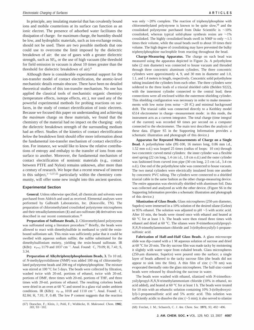
In principle, any insulating material that has covalently boundions and mobile counterions at its surface can function as anionic electret. The presence of adsorbed water facilitates thedissipation of charge: for maximum charge, the humidity shouldbe low, and hydrophilic materials, such as ion-exchange resins,should not be used. There are two possible methods that onecould use to overcome the limit imposed by the dielectricbreakdown of air: the use of gases with a greater dielectricstrength, such as SF6, or the use of high vacuum (the thresholdfor field emission in vacuum is about 10 times greater than thethreshold for dielectric breakdown of air).6
Although there is considerable experimental support for theion-transfer model of contact electrification, the atomic-levelmechanistic details remain obscure. There have been no detailedtheoretical studies of this ion-transfer mechanism. No one hasapplied the classical tools of mechanistic organic chemistry(temperature effects, isotope effects, etc.), nor used any of thepowerful experimental methods for probing reactions on sur-faces, in the study of contact electrification of ionic electrets.Because we focused this paper on understanding and achievingthe maximumcharge on these materials, we found that thechemistry of the material had no impact on the charging: onlythe dielectric breakdown strength of the surrounding mediumhad an effect. Studies of the kinetics of contact electrificationbelowthe breakdown limit should offer more information aboutthe fundamental ion-transfer mechanism of contact electrifica-tion. For instance, we would like to know the relative contribu-tions of entropy and enthalpy to the transfer of ions from onesurface to another. Moreover, the fundamental mechanism ofcontact electrification of nonionic materials (e.g., contactbetween PTFE and Nylon) remains unknown, after more thana century of research. We hope that a recent renewal of interestin this subject,1-3,37,55 particularly within the chemistry com-munity, will offer some new insight into this ancient question.
Experimental Section
General. Unless otherwise specified, all chemicals and solvents werepurchased from Aldrich and used as received. Elemental analyses wereperformed by Galbraith Laboratories, Inc. (Knoxville, TN). Thepreparation of chloromethylated crosslinked polystyrene microspheresand their tetraalkylammonium (1) and azo-sulfonate (4) derivatives wasdescribed in our recent communication.18
Preparation of Sulfonate Beads, 2.Chloromethylated polystyrenewas sulfonated using a literature procedure.67 Briefly, the beads wereallowed to react with dimethylsulfide in methanol to yield the resin-bound sulfonium salt. This resin was sufficiently polar that it could beswelled with aqueous sodium sulfite; the sulfite substituted for thedimethylsulfonium moiety, yielding the resin-bound sulfonate. IR(KBr): νSdO 1179 and 1037 cm-1. Anal. Found: C, 79.09; H, 7.41; S,3.34.
Preparation of Alkyltriphenylphosphonium Beads, 3.To 10 mLof N-methylpyrrolidinone (NMP) was added 100 mg of chloromethy-lated polystyrene beads and 200 mg of triphenylphosphine. The mixturewas stirred at 100°C for 5 days. The beads were collected by filtration,washed twice with 20-mL portions of ethanol, twice with 20-mLportions of DMF, three times with 20-mL portions of THF, and threetimes with 20-mL portions of ethanol. The resulting colorless beadswere dried in an oven at 60°C and stored in a glass vial under ambientconditions. IR (KBr): νP-Ph 1018 and 1110 cm-1. Anal. Found: C,82.84; H, 7.01; P, 0.48. The low P content suggests that the reaction
was only∼20% complete. The reaction of triphenylphosphine withchloromethylated polystyrene is known to be quite slow,68 and thecrosslinked polystyrene purchased from Duke Scientific is∼10%crosslinked, whereas typical solid-phase synthesis resins are∼1%crosslinked. The highly crosslinked beads swell in NMP to only∼1.5times their volume, while the usual beads swell to about 10 times theirvolume. The high degree of crosslinking may have prevented the bulkytriphenylphosphine nucleophile from reacting throughout the bead.
Charge-Measuring Apparatus. The charge on each bead wasmeasured using the apparatus depicted in Figure 2a. A polyethylenetube (2 mm diameter) was connected to house vacuum and threadedthrough three concentric aluminum cylinders. The three concentriccylinders were approximately 4, 9, and 30 mm in diameter and 1.0,1.1, and 1.4 meters in length, respectively. Concentric solid polyethylenetubing insulated the cylinders from each other. The three cylinders weresoldered to the three leads of a triaxial shielded cable (Belden 9222),with the innermost cylinder connected to the central lead; theseconnections were all enclosed within the outermost shielding cylinder.This shielding configuration was necessary in order to make measure-ments with low noise (rms noise∼20 fC) and minimal backgrounddrift. The triaxial cable was connected directly to a Keithley model6514 electrometer in charge-measurement mode: in this mode, theinstrument acts as a current integrator. The total charge (time integralof the current) was recorded 60 times per second on a computerconnected to the electrometer. The main text describes the analysis ofthese data. (Figure S5 in the Supporting Information provides aschematic illustration and photograph of this device.)
Apparatus for Repeated Measurements of Charge on a SingleBead. A polyethylene tube (PE-100, 16 meters long, 0.86 mm i.d.,1.52 mm o.d.) was looped 25 times (radius of loops: 10 cm) throughtwo concentric curved metal cylinders: the inner cylinder was a flexiblesteel spring (22 cm long, 1.4 cm i.d., 1.8 cm o.d.) and the outer cylinderwas fashioned from curved iron pipe (30 cm long, 2.5 cm i.d., 3.4 cmo.d.). One end of the polyethylene tube was connected to house vacuum.The two metal cylinders were electrically insulated from one anotherby concentric PVC tubing. The cylinders were connected to a shieldedtriaxial cable in the same fashion as the other charge-measuring device.The entire apparatus was electrically shielded with aluminum foil. Datawas collected and analyzed as with the other device. (Figure S6 in theSupporting Information provides a schematic illustration and photographof this device.)
Silanization of Glass Beads.Glass microspheres (250-µm diameter,Supelco) were immersed in a 10% solution of the desired silane (Gelest)in 95% ethanol. The solution was adjusted to pH∼5 with acetic acid.After 10 min, the beads were rinsed once with ethanol and heated at60 °C for at least 1 h. The beads were then rinsed three times withethanol and dried at 60°C. The silanes wereN-trimethoxysilylpropyl-N,N,N-trimethylammonium chloride and 3-(trihydroxysilyl)-1-propane-sulfonic acid.
Fabrication of Half-and-Half Glass Beads.A glass microscopeslide was dip-coated with a 1 Maqueous solution of sucrose and driedat 60°C for 20 min. The dry sucrose film was made tacky by moisteningit slightly with water vapor from exhaled breath. Glass microspheres(250-µm diameter, Supelco) were poured onto the surface; a singlelayer of beads adhered to the tacky sucrose film (the beads did notappear to sink into the film). A thin film of zinc (∼70 nm) wasevaporated thermally onto the glass microspheres. The half-zinc-coatedbeads were released by dissolving the sucrose in water.
The beads were washed with ethanol, silanized withN-trimethox-ysilylpropyl-N,N,N-trimethylammonium chloride (10% in ethanol, noacid added), and heated at 60°C for at least 1 h. The beads were treatedfor 10 min with an ethanolic solution containing 10% 3-(trihydroxysi-lyl)-1-propanesulfonic acid and 5% acetic acid. This solution wassufficiently acidic to dissolve the zinc (∼5 min); it also served to silanize
(67) Doescher, F.; Klein, J.; Pohl, F.; Widdecke, H.Makromol. Chem.1982,183, 93-102. (68) Frechet, J. M.; Schuerch, C.J. Am. Chem. Soc.1971, 93, 492-496.
Electrostatic Charging of Surfaces A R T I C L E S
J. AM. CHEM. SOC. 9 VOL. 129, NO. 13, 2007 4087

the newly exposed glass surface. The beads were washed once withethanol and dried at 60°C. To image the distribution of charge onthese glass beads, we combined in a glass dish ca. 0.5 mg of 20-µm-diameter polystyrene microspheres with tetraalkylammonium function-ality (1) with ca. 30 of the glass microspheres with half-and-half surfacecharge. The dish was agitated manually for 30 s. Each glass bead hada disordered, incomplete monolayer of 20-µm polystyrene spheresadhered to roughly one-half of the bead, as shown in the inset in Figure10c.
Patterning of Silanes on a Silicon Surface.Silanes were printedon a silicon surface (with oxide) using microcontact printing.45 Poly-(dimethylsiloxane), PDMS (Dow Corning, Sylgard 184), was pouredover a photolithographically fabricated master. After curing at 65°Cfor 2 h, the PDMS was oxidized in an oxygen plasma for∼60 s andsilanized with the desired silane (1%N-trimethoxysilylpropyl-N,N,N-trimethylammonium chloride in 95% ethanol/water). The stamp waswashed thoroughly with ethanol and dried with a stream of N2. A 0.05%solution of the same silane in ethanol was spin-coated on a gold “inkerpad”65 (a silicon wafer with∼5 nm of Cr and∼70 nm of Au) at 3000rpm for 30 s. The silanized PDMS stamp was “inked” by contact withthis inker pad for 60 s. The stamp was then placed for 30 s on a plasma-cleaned silicon wafer with a∼300 nm thermally grown oxide layer(Universitywafer.com). This silanized wafer was allowed to sit at roomtemperature for 2 h and then immersed in a 1% solution of 3-(trihy-droxysilyl)-1-propanesulfonic acid in 95% ethanol/water for 10 min.The wafer was washed thoroughly with ethanol and dried with a streamof N2.
Surface Potential Measurements.The surface topography andsurface potential were imaged with an AFM (D3100, NSIV; DigitalInstruments). The topographic images were obtained using the AFMin tapping mode and the KFM images were obtained using the AFMin surface potential mode.
Patterning of Silanes on Glass Microspheres.A glass microscopeslide was coated with a∼1 mm layer of PDMS (Sylgard 184, Dow
Corning). Glass microspheres (250-µm diameter, Supelco) wereclamped between this PDMS-coated slide and a plain glass microscopeslide. The PDMS conformed to a small spot around the north pole ofeach sphere. The spheres were immersed in a solution ofN-trimethox-ysilylpropyl-N,N,N-trimethylammonium chloride (10% in ethanol,adjusted to pH∼5 with acetic acid) for 10 min. The spheres were washedonce with ethanol and the silane layer cured at 60°C for 1 h. Thebeads were removed, washed again with ethanol, and silanized with asolution of 3-(trihydroxysilyl)-1-propanesulfonic acid (10% in ethanol,adjusted to pH∼5 with acetic acid). The beads were washed threetimes with ethanol and dried at 60°C.
Self-Assembly on Glass Microspheres with Patterned Charge.Following the procedure reported in our recent communication,18 wecombined in an aluminum dish ca. 0.5 mg of 20-µm-diameterpolystyrene microspheres with tetraalkylammonium functionality (1)with ca. 30 of the glass microspheres with patterned surface charge.The dish was agitated manually for 30 s. Most of the glass sphereshad a small “clump” of adherent 20-µm beads (as shown in Figure11b); about a quarter of the glass spheres had no adherent beads.
Acknowledgment. This research was supported by the ArmyResearch Office (Grant W911NF-04-1-0170) and used theshared Resource Facilities supported by the National ScienceFoundation under NSEC (PHY-0117795) and MRSEC (DMR-0213805) awards. The authors would like to thank Dr. EmilyWeiss for assistance with the KFM measurements.
Supporting Information Available: Histograms of the mea-surements of charge for all experiments discussed in the article,and photographs of the two devices used to measure charge onsingle microspheres. This material is available free of chargevia the Internet at http://pubs.acs.org.
JA067301E
A R T I C L E S McCarty et al.
4088 J. AM. CHEM. SOC. 9 VOL. 129, NO. 13, 2007