Embed Size (px)
Citation preview
Pram~na, Vol. 19, No. 3, September 1982, pp. 279-288. ¢~) Printed in India.
Ion source scaling laws
R JONES Department of Physics, National University of Singapore, Kent Ridge, Singapore 0511
MS received 16 March 1982; revised 1 July I982
Abstract. Simple theory and basic plasma physics experiments are used to deduce scaling laws for ion source discharges.
Keywords. Ion sources; plasma discharges.
1. Introduction
Much o f the progress made in controlled thermonuclear research can be traced to the advent of intense and effiicient neutral beam injectors. Conversely, these promising results serve to spur on the development of still more efficient sources having improved characteristics.
Despite the considerable worldwide effort there is still only a partial understanding of the impedance characteristics and operating regimes o f such ion source devices. The present paper is par t of a continuing long range effort to develop sealing laws for the modelling o f ion source discharges.
2. The experimental device
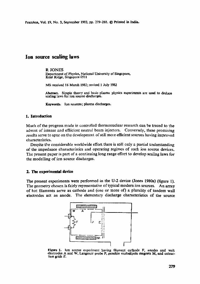
The present experiments were performed in the U-2 device (Jones 1980a) (figure 1). The geometry chosen is fairly representative o f typical m o d e m ion sources. An array o f hot filaments serve as cathode and (one or more of) a plurality o f tandem wall electrodes act as anode. The elementary discharge characteristics o f the source
~/////////////A W A
[
,11
Eij2 . , .
~ ° .
° , .
M: jl[ I I
Figure 1. Ion source experiment having filament cathode F, anodes and wall electrodes A and W, Langmuir probe P, possible multldipole magnets M, and extrac- tion grids E.
279

280 R Jones
(but neglecting details due to geometry and electrode biasing) are well understood within the context of zero-dimensional (Jones 1979a) and one-dimensional (Tonks and Langmuir 1929, Jones 1977a) particle and energy balance models while anomalous transport (Jones 1977b, 1980b) and noise (Jones 1978a, 1979b) can be neglected for the present purposes.
Diagnostics consist of Langmuir probes and high resolution planar-gridded retarding field electrostatic energy analyzers (Jones 1978b). The ambient source parameters for the present experiments range according to: 0.4<T~<3, l < T e < 1 5 , 108<ne<10 lz, and 10-6<p< 10 -2 where Tl and Te are the ion and electron plasma temperatures respectively (in electronvolts), ne is the plasma density (in cm -3) andp is the neutral gas pressure (in torr).
Details of the anode (and overall source) geometry and electrical configuration are variable from one ion source design to another and can be neglected when asking certain rather basic questions. Elementary particle balance, for instance, is often obtained under the assumption that the plasma is in contact with a single, uniform, conducting wall (Auer 1961). That is, anode and cathode bias are ignored altogether. While rigorously derivable only for certain RF sustained discharges this model can nonetheless be applied with considerable success (Jones 1977a) to a wide range of devices.
3. Simple zero-dimensional theory
It is well-known that for gas pressures less than some critical value no discharge can be struck (or sustained) at all (Bohm 1949). This behaviour holds true over quite a range of electrode geometries and electrical circuitry and biasing. Minimum opera- ting pressures are now understood for ion source plasmas sustained solely by secondary (plasma) electron-gas ionization (Jones 1978c, 1979b). Primary electron sustained discharges also have clitical gas pressures (which are lower still), however, and this limitation has remained a mystery for some years now. (Primary sustained dis- charges having ionization mean free paths exceeding the plasma dimensions are often preferred because of the high degree of plasma homogeneity (Jones 1980c) and, thence, low ion beam energy spread that results.)
We have been assuming that the source discharge has a filament cathode which emits a surplus of (primary) electrons into the surrounding ionizable gas. The space charge limitation of this electron emission current density Je is then relaxed by the addition of plasma ions into the plasma-filament sheath. According to Tonks and Langmuir (1929):
de/d i <~ (rndme)t/~, (1)
where Jl is the ion current density entering the sheath. This relation has been verified repeatedly. For a recent example, under similar plasma conditions, Stenzel (1978) may be referred to.
The total ion current flowing in the source li is limited by the gas ionization rate (Stifling et al 1979):
v (2) I, = Zon . I~ ~ ,

1on source scaling laws 281
where Z is the ionic change, ~ is the electron-gas ionization crossseetion, n, is the neutral density (in cm-3), le is the total primary (ionizing) electron current, A is the discharge area and V is the discharge volume. We assume here that the discharge is sustained solely by monoenergetic primary electrons (Jones 1978c). Pressure limitation for discharges sustained by thermal (plasma) electrons has been tleated in previous publications (Jones 1978c, 1979a).
As the gas pressure is reduced, the plasma ion density drops, the filament sheath expands, the plasma potential becomes negative (with respect to the wall, figure 2), and the ion flow is directed towards the (more negative) filament cathode. Relating de,i and 1~, i via a common sheath area and combining (1) and (2), we obtain (for Z = 1) the neutral density limitation:
A n, >1 (melton) 1/2 .~-~, (3)
which indicates how the discharge (electrode) area establishes the low pressure operat- ing limit.
Equation (3) has been compared with experiments conducted in a number of gases and for several electrode configurations. The comparisons (table 1) are reasonably close considering the simplifications made in the theory and the usual experimental uncertainties.
For higher neutral pressures, the plasma density and available ion beam current at first increase (as suggested by equation (2)). As the ionization mean free pa th drops (to values less than the plasma dimensions), however, the plasma density and homo- geneity again deteriorate. (High neutral pressure also enhances the magnetic cusp leak width and hence, particle losses.)
i ,
- 6 0 - -
Vp - 4 T
--4 --
-2 8
I I I o 10 -5 10-3
P
Figure 2. Electron temperature T (in.eV) and plasma, potential, F'p (in voltsl) as a f u n c t i o n o f neutral pressure P (in torrJ.

282 R Jones
Table 1. Discharge neutral pressure limitation.
Ionization Pmin Pmin Gas Wall area (cm0 cross-section (theory, (experiment, (cm 2) torr) torr)
Argon 300 3 x 10 -xs 8 × 10 -~ 2 × 10 -5 Argon 10 (effective) 3 x 10 -is 3 x I0 -s 1 x 10 -4 Helium 300 5 × 10 -17 3 x 10 -4 1 × 10 -4 Helium 10 (effective) 5 × 10 -x~ 1 × 10 -5 1 × l0 -s Hydrogen 10 (effective) 7 × 10 -~7 1 × 10 -5 7 × 10 -6
Source volume = 2000 cm s
4. Model of the double anode discharge
Many ion sources make use of multiple anodes o f differing size and/or electrical bias potential. We have studied such discharges in their archetypal form, the 'double anode' discharge. (The 2 anodes having areas A A and As, respectively.) (generali-
zation to N anodes is straightforward). For equal 'effective electrode areas' (physical size plus the effect of any magnetic
insulation) the most positively-biased electrode fixes the plasma potential (at the electrode voltage plus a few Te). For unequal effective electrode area, however, a non- trivial problem results, provided that the smaller 'anode" is the more positively-biased (this problem was qualitatively discussed in Tonks and Langmuir 1929). In this ease, the plasma potential may fall somewhere between the potentials of the various electrodes ( 'anodes').
In the presence o f only one single (large) anode (defined, conventionally, as the zero o f voltage) the plasma will assume a space potential V n which is some few T, positive with respect to the anode. This potential difference will assure that electrons are electrostatically confined and maintain discharge neutrality. A small 'auxiliary' electrode can be added and, so long as it is biased negatively with respect to the large anode, will have little influence on the discharge.
If, however, the (small) auxiliary electrode is biased very positively it will act as an effective electron sink despite its small area As. Assuming a Maxwellian distribution, the electron current flowing to this 'auxiliary anode ' will be approximately
( eV~ -- eVp~ e ne(Td2zrme) xn As 1 + ~ ], 1 <.~ oc ~ 2, (4)
where Vs is the bias voltage (positive) placed on the auxiliary anode. The first term in the second set of brackets in (4) accounts for the usual electron
saturation current. In ideal theory, the second term would not appear. In most real plasma electrode experiments, however, the electron current does not saturate but continues to rise following a roughlyl inear dependence on bias voltage. This is discussed in Taylor and Leung (I976) and Spalding (1970). For the present experi- ment (with small auxiliary anode), this current-voltage relationship has been verified

Ion source scaling laws 283
experimental ly (figure 3). At the same time, the electron current flowing to the large anode will be limited to:
e n~(T~/2~m]) 1/'~ A A exp ( - - eV./T~). (5)
where A n is the area o f tile large anode and its potential is again defined to be zero.
To maintain charge neutrali ty in the source, these two currents (equations (4) and (5)) must balance the ion current:
[3 Z e n~ (2T~/mi) ~ ~ A A, (6)
with/3 a constant o f order I. (We assume that the cathode area is much less than A A
and that the auxiliary anode is too positive to collect ions.) Combining (4), (5) and (6) and assuming that /3 and Z = 1, we obtain:
AA(4wm~)l/e = m~/2 ~ A A e x p ( _ eVp/T~) + A~[1 + e(V~ -- Vp)]i " (7) • aT~
We can see f rom (7) that as V~ increases the plasma potential , Vo must also increase. Physically, as the auxil iary anode becomes more positive, the plasma potential must rise also in order to mainta in a satisfactory overall electron confinement.
P.---6
le
9 --
6 -
l
j 1 o l
10 v~
Figure 3. Electron current le (in mA) drawn to a small auxiliary electrode as a func- tion of electrode (positive) bias voltage V s. Solid curve: experiment. Dotted curve: theory equation (4), a ~ 1.

284 R Jones
5. Experimental observations
We have sought to verify the behaviour of (7) experimentally. The filament cathode was biased 50 volts negative and the entire source wall served as the large grounded anode. A small 4 cm square tantalum plate was immersed in the centre of the plasma and served as the small, variably biased, auxiliary anode. The current flowing to the large anode (source wall) remained roughly constant at 4.4 amperes as the auxiliary anode voltage was adjusted.
Langmuir p robe observations of the plasma were made as a function of bias on the auxiliary anode (figure 4). Negative biases on the auxiliary anode had no effect on the p lasma whatever. As the bias exceeded a few T e positive with respect to ground, however, the p lasma potential began to lise. The current to the auxiliary anode (4) also rose with the bias, as indicated in figure 4. Clearly, the auxiliary electrode is beginning to share in the role of current collector and is altering the plasma potential as predicted by eq. (7).
In table 2, we compare the observed values o f e V p / T e with those computed f rom (7). Just as in conventional single anode discharges (Liu 1974), the theory over- estimates the experimental values somewhat (perhaps at tr ibutable to pr imary electron injection).
We have also investigated the impedance characteristics o f the dishcarge by varying the arc voltage while keeping the filament (heating) current and neutral gas pressure fixed. Results were obtained for several different anode areas in a magnetic field free discharge (figure 5) and for a single anode a r rangement but with variable multi- dipole confining magnetic field (figure 6). In the later case, the anode area is given approximately by the ion gyroradius multiplied by the total cusp length (Jones 1979c; Stirling et a l 1979; Pechacek 1980).
Small effective anode areas are desired in order to reduce parasitic energy, pr imary
(¢)
f
0 10 V
Figure 4. Differentiated Langmuir probe characteristics ( f versus probe voltage V) obtained in the source plasma for various values of lauxiliary anode bias. Auxiliary anode bias; a = between - 50 and 0 V, b = ÷20V, c = +35V, rd = ÷37V. Auxi- liary anode current: a = <1 mA, b = 10 rnA, c = 40 mA and d = 53 mA.

e Vp/Te e V~/Te (experiment) (theory)
285
100
20 7 3 5
35 14 3"5 7
37 15 4 8-8
B
V
Ion source scaling laws
Table 2. Plasma potential variation.
V s e ( V s - - V I ~ ) / T e
(volts) (experiment)
I 0 8
[
Figure 5. Arc current I (in amperes) as a function of arc voltag• V (in volts). Anode a r e a : a = 8 0 c m 2 , b = 30cm 2 , c = 1 5 c m z. Source volume=2000cm 3.
electron and plasma loss. In the multiple electrode source configuration, a small anode can be held positive to control the plasma potential (which must be positive with respect to the outside world if ions are to be extracted) while the walls proper are biased negatively to repel electrons. Unfortunately, for the smallest anode areas investigated experimentally discharges could only be struck (or maintain- ed) at relatively high arc voltages (anode-to-cathode voltage drop). The high voltage portions of figures 5 and 6 are emission-limited (the filament heating being fixed) while the lower voltage operating region (where accessible, for large enough anode area) is the space charge limit studied by us previously (Jones 1978c).
For small anode area low discharge voltage results in zero ion extraction. This is shown in detail in figure 7 where the minimum permissible arc voltage is displayed as a function of neutral pressure. Similar curves are generated when we regulate (fix) the arc current (or, alternatively, the ion beam current) at some (arbitrary) value and measure the arc voltage drop observed as a function o f gas pressure (figure 8).

2 8 6 R Jones
1 0 0 - -
(0)
0
Figure 6. r ive a n o d e a r e a : a : 75 cna 2, b = 30 cm ~, c =: 15 crn 2.
I 4 8 t
A r c c u r r e n t I ( in a m p e r e s ) a s a f u n c t i o n o f a r c v o l t a g e V ( in vol t s ) . Effec . S o u r c e v o l u m e - 2 0 0 0 c m a-
100
(a l I I
O 10
g
F i g u r e 7. M i n i m u m a rc v o l t a g e Vudn (ill v o l t s ) a s a f u n c t i o n o f s o u r c e n e u t r a l g a s p r e s s u r e P, ( in m t o r r ) A n o d e a r e a : a - - 30 c m -~, b = 25 cm% c : 1 5 c m ~.
V I 0 °
0 I I 10
P
F i g u r e g. O b s e r v e d a r c v o l t a g e V ( in v o l t s ) a t c o n s t a n l a r c c u r r e n t ( I ~ 3 aml~cres) a s a f u n c t i o n o f s o u r c e n e u t r a l ga s p r e s s u r e P, in m t o r r . A n o d e a r e a ~ 50 c m L

Ion source scaling laws 287
6. Anode area l imitation model
It is common practice to bias the source wall negative, in order to maximize electron confinement, and use (as small as possible) a positive anode V~, A~ to maintain Vp > 0 (as required for subsequent ion extraction from the source plasma to an outside world at ground potential).
We can treat this problem using (7) (assuming V~ > V~) where the wall (including ion beana area) is identified as A A and is biased sufficiently negatively so as
to repel primaries (and thence, plasma electrons as well). Under this assumption, the current ofeq . (5) is neglected and (7) simplifies to (keeping/3 and Z):
f l Z , - l~ff[-~, A A = A ~ l } - . (8 )
Combining this with our requirement for beam extraction:
Ve ~>0, (9)
we obtain:
A , . . /3z(4 rrm~"mi)~ - - ~ , ( l O ) A 4 1 - - (e V~/~ re ) '
(but not so large as to violate V~ > Vp). Equation (10) is in qualitative agreement with figure 7. A minimum anode area
_4~, is observed experimentally and this limitation is relaxed as the arc voltage (and hence V~) increases. A pressure dependence (figure 7) is not contained explicitly in the model but it is known, experimentally (figure 2), that T~ (in eq (10)) varies inversely with gas pressure so that a pressure increase can play the role of an increase in /,~ (in agreement with figures 7 and 8). (For fixed discharge parameters I~ power P, ionization energy E 1, etc., simultaneous particle,
\ tFI i ]
and energy balance,
P Ane tni ( E l l eVp I-2T,.), (12)
predict such a dependence of T,. on n,:
E" [~ Ie V \ I _ (2 T e -~ eV, ~- i) [e--ff'A)' (13) MI!
(Jones 1979a). We have assumed here that the neutral density is an independent, externally controlled variable. At very high powers, however, neutral penetration
288 R J o n e s
o f the p l a s m a b e c o m e s difficult, ' a r c s t a rva t i on ' sets in, a n d the neu t ra l dens i ty in the p l a s m a core d rops . This, in turn, a l lows a co re e l ec t ron t empe ra tu r e rise.
7. Conclusions
Simple t heo ry a n d bas ic p l a s m a physics exper imen t s have been used to deduce some scal ing laws for ion source discharges. The L a n g m u i r shea th s tab i l i ty equa t ion a n d the gas i on i za t i on r a t e comb ine to impose a l i m i t a t i o n o n t h e neu t ra l fill p ressure . The de ta i l ed resu l t is verified exper imenta l ly . Th is p r e s su re l imi ta t ion in tu rn c o m b i n e s wi th p o w e r and par t ic le ba lance to i m p o s e r e s t r a in t s on e lec t ron p l a s m a
t empe ra tu r e . T h e or ig in a n d i m p o r t a n c e o f a n o d e area l im i t a t i on Ls p o i n t e d out and a mode l
o f the d o u b l e a n o d e d ischarge is f o rmu la t ed a n d c o m p a r e d (qual i ta t ive ly) with
exper imen t .
R eferences
Auer P L 1961 Proc. 5th International Conf. on lonisation Phenomena in Gases, Munich, p. 297 Bohm D 1949 Characteristics o f electrical discharge in m~gnetic fields (eds.) A. Guthrie and
R. Wakerling, (New York : McGraw-Hill) Jones R 1977a Ptasnta Phys. 19 259 Jones R 1977b Can. J. Phys. 55 1356 Jones R 1978a J. PlasJmt Phys. 20 221 Jones R 1978b Rev. Sci. lnstrum. 49 21 and 50 392 Jones R 1978cJ. Indian Inst. Sci. 60 71 Jones R 1979a Pramana 12 1 Jones R 1979b Plasma Phys. 21 399 Jones R 1979c Plasma Phys. 21 505 Jones R 1980a Pramana 18 99 Jones R 1980b 1EEE Trans. Plasma Sci. 8 14 Jones R 1980c Phys. Rep. 61 295 Liu H 1974 Ph.D. thesis, Plasma production by beam plasma discharge Stevens Institute of Tech. Pechacek R E 1980 NRL report 4162 Spalding I 1970 Advances in plasma physics, Vol. 4, (New York: Wiley) Stirling W L, Ryan P M, Tsai C C and Leung K N 1979 Rev. Sei. Instrum. 50 102 Stenzel R L 1978 Phys. Fluids 21 93 Tonks L and Langmuir I 1929 Phys. Rev. 34 876 Taylor G R and Leung K N 1976 Rev. Sci. lnstrum. 47 614