Embed Size (px)
Citation preview
Carnegie Mellon
1
Design of Digital Circuits 2017Srdjan CapkunFrank K. Gürkaynak
Adapted from Digital Design and Computer Architecture, David Money Harris & Sarah L. Harris ©2007 Elsevier
http://www.syssec.ethz.ch/education/Digitaltechnik_17
I/O Systems

Carnegie Mellon
2
What Will We Learn?
How to Interface Peripherals
Memory Mapped I/O
Memory Mapped I/O Example
▪ Speech Chip (SPO 256)
Carnegie Mellon
3
What Can Our Processor Do So Far?
We can:
▪ Calculate
▪ Write to and Read from memories
▪ Branch, loop, jump and return to sub-programs
But how do we interact with the environment?
▪ Light the LEDs on the board
▪ Read the buttons
▪ More complex interfaces, keyboards, video connections

Carnegie Mellon
4
Memory-Mapped Input/Output (I/O)
Access I/O devices (like keyboards, monitors, printers) just like it accesses memory
▪ Each I/O device assigned one or more address
▪ When that address is detected, data is read from or written to I/O device instead of memory
▪ A portion of the address space dedicated to I/O devices(for example, addresses 0xFFFF0000 to 0xFFFFFFFF in reserved segment of memory map)
But we need additional hardware to help us
▪ After all we will not really write to and read from memory
Carnegie Mellon
5
Memory-Mapped I/O Hardware
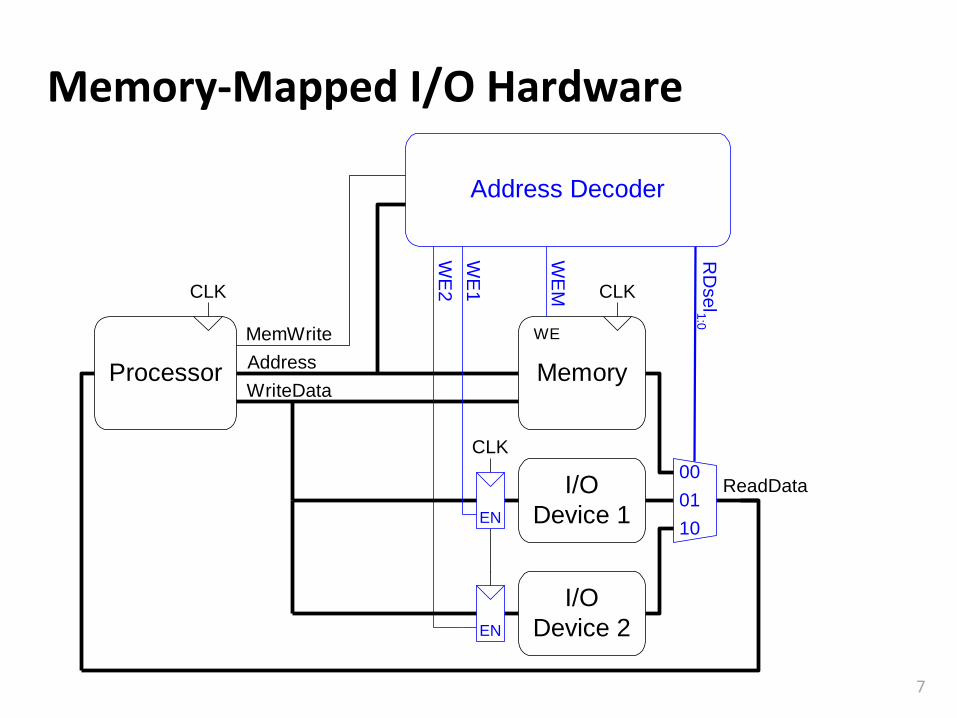
Address Decoder:
▪ Looks at address to determine which device/memory communicates with the processor
I/O Registers:
▪ Hold values written to the I/O devices
ReadData Multiplexer:
▪ Selects between memory and I/O devices as source of data sent to the processor
Carnegie Mellon
6
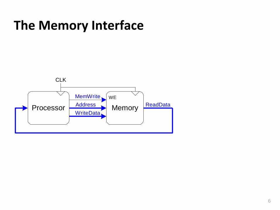
The Memory Interface
Processor MemoryAddress
MemWrite
WriteData
ReadData
WE
CLK
Carnegie Mellon
7
Memory-Mapped I/O Hardware
Processor MemoryAddress
MemWrite
WriteData
ReadDataI/O
Device 1
I/O
Device 2
CLK
EN
EN
Address Decoder
WE
WE
M
RD
se
l1:0
WE
2
WE
1 CLK
00
01
10
CLK
Carnegie Mellon
8
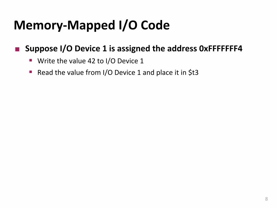
Memory-Mapped I/O Code
Suppose I/O Device 1 is assigned the address 0xFFFFFFF4
▪ Write the value 42 to I/O Device 1
▪ Read the value from I/O Device 1 and place it in $t3

Carnegie Mellon
9
Memory-Mapped I/O Code: Write
addi $t0, $0, 42sw $t0, 0xFFF4($0)
# Recall that the 16-bit immediate # is sign-extended to 0xFFFFFFF4
Processor MemoryAddress
MemWrite
WriteData
ReadDataI/O
Device 1
I/O
Device 2
CLK
EN
EN
Address Decoder
WE
WE
M
RD
se
l1:0
WE
2
WE
1 =
1
CLK
00
01
10
CLK
Write 42 to I/O Device 1 (0xFFFFFFF4)
Carnegie Mellon
10
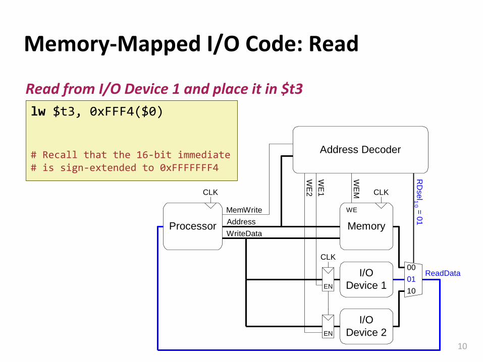
Memory-Mapped I/O Code: Read
lw $t3, 0xFFF4($0)
# Recall that the 16-bit immediate # is sign-extended to 0xFFFFFFF4
Processor MemoryAddress
MemWrite
WriteData
ReadDataI/O
Device 1
I/O
Device 2
CLK
EN
EN
Address Decoder
WE
WE
M
RD
se
l1:0 =
01
WE
2
WE
1 CLK
00
01
10
CLK
Read from I/O Device 1 and place it in $t3
Carnegie Mellon
11
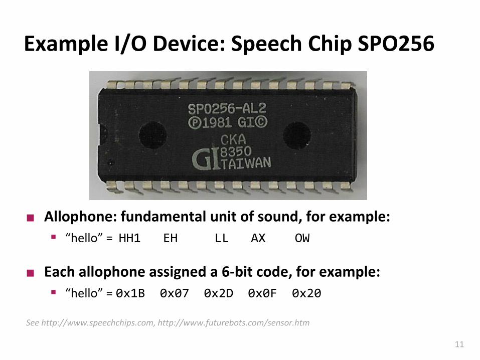
Example I/O Device: Speech Chip SPO256
Allophone: fundamental unit of sound, for example:
▪ “hello” = HH1 EH LL AX OW
Each allophone assigned a 6-bit code, for example:
▪ “hello” = 0x1B 0x07 0x2D 0x0F 0x20
See http://www.speechchips.com, http://www.futurebots.com/sensor.htm
Carnegie Mellon
12
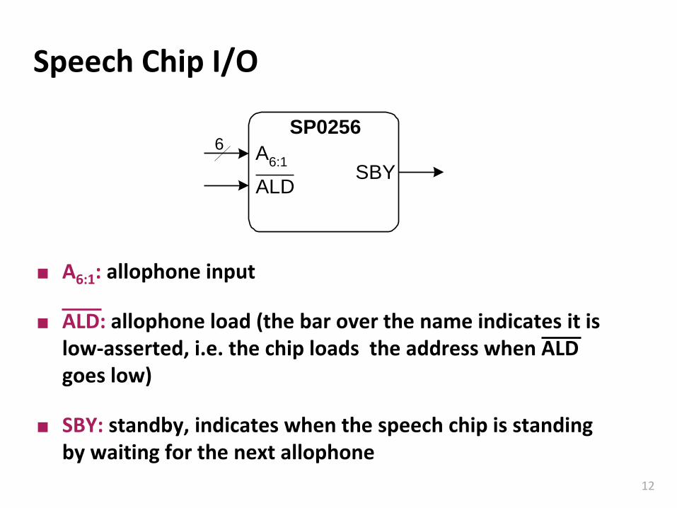
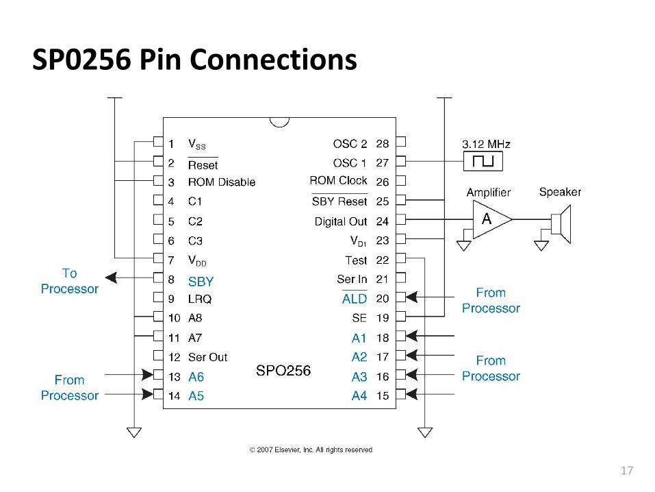
Speech Chip I/O
SP0256
A6:1
ALDSBY
6
A6:1: allophone input
ALD: allophone load (the bar over the name indicates it is low-asserted, i.e. the chip loads the address when ALD goes low)
SBY: standby, indicates when the speech chip is standing by waiting for the next allophone
Carnegie Mellon
13
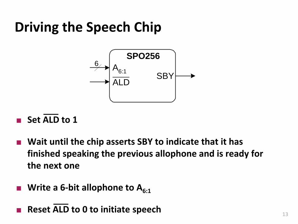
Driving the Speech Chip
SPO256
A6:1
ALDSBY
6
Set ALD to 1
Wait until the chip asserts SBY to indicate that it has finished speaking the previous allophone and is ready for the next one
Write a 6-bit allophone to A6:1
Reset ALD to 0 to initiate speech
Carnegie Mellon
14
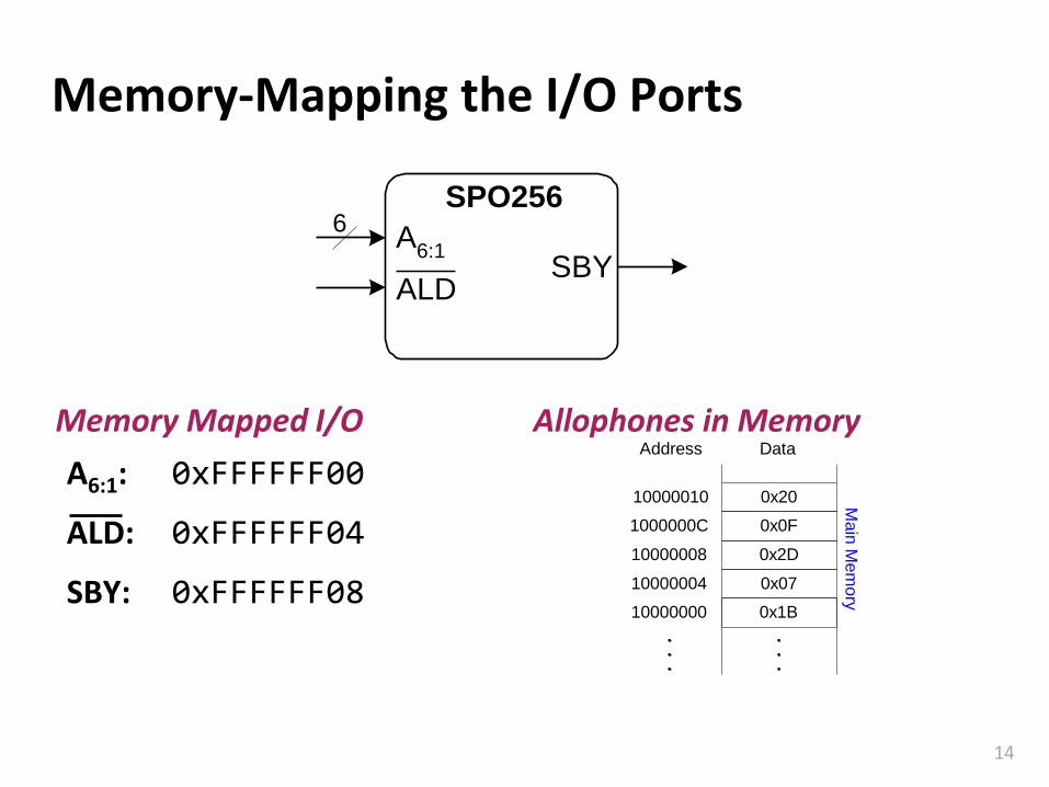
Memory-Mapping the I/O Ports
A6:1: 0xFFFFFF00
ALD: 0xFFFFFF04
SBY: 0xFFFFFF08
Data
1000000C
10000008
10000004
Address
0x20
0x0F
0x2D
0x07
0x1B10000000
10000010 Main
Mem
ory
Memory Mapped I/O Allophones in Memory
SPO256
A6:1
ALDSBY
6
Carnegie Mellon
15
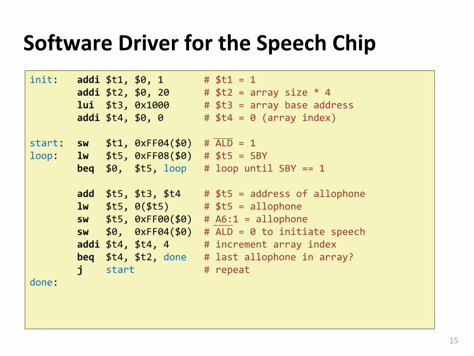
Software Driver for the Speech Chip
init: addi $t1, $0, 1 # $t1 = 1 addi $t2, $0, 20 # $t2 = array size * 4lui $t3, 0x1000 # $t3 = array base addressaddi $t4, $0, 0 # $t4 = 0 (array index)
start: sw $t1, 0xFF04($0) # ALD = 1loop: lw $t5, 0xFF08($0) # $t5 = SBY
beq $0, $t5, loop # loop until SBY == 1
add $t5, $t3, $t4 # $t5 = address of allophonelw $t5, 0($t5) # $t5 = allophonesw $t5, 0xFF00($0) # A6:1 = allophonesw $0, 0xFF04($0) # ALD = 0 to initiate speechaddi $t4, $t4, 4 # increment array indexbeq $t4, $t2, done # last allophone in array?j start # repeat
done:
Carnegie Mellon
16
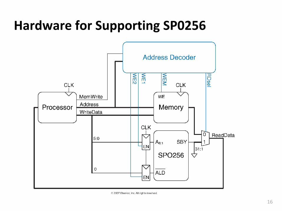
Hardware for Supporting SP0256
Carnegie Mellon
17
SP0256 Pin Connections
Carnegie Mellon
18
Summary
Processors access I/O devices just like memory
A range of memory addresses is reserved for I/O
An address decoder detects when we access I/O
▪ It enables the I/O device or memory for writing
▪ Selects between the I/O device or memory for reading
A device driver is customized software routine to allow interfacing the I/O device.
▪ Device driver knows how the external hardware needs to be accessed.