Embed Size (px)
Citation preview
20-GSample/s (10 GHz � 2 Clocks) Burst-Mode CDR Based on Injection Locking and Space Sampling for Multiaccess NetworksVolume 4, Number 5, October 2012
Bhavin J. Shastri, Member, IEEEPaul R. Prucnal, Fellow, IEEEDavid V. Plant, Fellow, IEEE
DOI: 10.1109/JPHOT.2012.22165151943-0655/$31.00 ©2012 IEEE
Invited Paper
20-GSample/s (10 GHz � 2 Clocks)Burst-Mode CDR Based on InjectionLocking and Space Sampling for
Multiaccess NetworksBhavin J. Shastri,1 Member, IEEE, Paul R. Prucnal,1 Fellow, IEEE, and
David V. Plant,2 Fellow, IEEE
(Invited Paper)
1Lightwave Communications Laboratory, Department of Electrical Engineering,Princeton University, Princeton, NJ 08544 USA
2Photonic Systems Group, Department of Electrical and Computer Engineering,McGill University, Montreal, QC H3A 2A7, Canada
DOI: 10.1109/JPHOT.2012.22165151943-0655/$31.00 �2012 IEEE
Manuscript received July 11, 2012; revised August 17, 2012; accepted August 28, 2012. Date ofpublication August 31, 2012; date of current version September 11, 2012. The work of B. J. Shastri wassupported by the Natural Sciences and Engineering Research Council of Canada (NSERC)Postdoctoral Fellowship. Corresponding author: B. J. Shastri (e-mail: [email protected]).
Abstract: In this paper, we demonstrate a novel 20-GSample/s burst-mode clock and datarecovery (BM-CDR) technique for optical multiaccess networks. The BM-CDR incorporatesan injection-locking method for clock recovery and a clock phase aligner employing spacesampling with two multiphase clocks at 10 GHz and a phase-picking algorithm for automaticclock phase acquisition. The design provides low latency and fast response withoutrequiring a reset signal from the network layer. The BM-CDR achieves a bit error rateG 10�10 while featuring instantaneous (0-bit) phase acquisition for any phase step ð�2� radÞbetween successive bursts. We also compare the data with probabilistic theoretical pre-dictions to validate the experimental results.
Index Terms: Access networks, burst mode (BM), clock and data recovery (CDR), clockphase aligner (CPA), injection locking, probabilistic theory, space sampling.
1. IntroductionThe past decade has seen profound changes not only in the way we communicate but also in ourexpectations of what networks will deliver in terms of speed and bandwidth. More specifically, theexplosive growth in Internet traffic has spurred the development of fiber-to-the-home (FTTH)systems for high-speed broadband access [1], [2]. Among them, passive optical network (PON) isrecognized as the most economical FTTH solution to alleviate the bandwidth bottleneck in accessnetworks [2], [3]. PON standards based on time-division multiplexing (TDM) such as the IEEE802.3ah gigabit ethernet PON (GEPON) [4] and ITU-T G.984 gigabit-capable PON (GPON) [5]have already been widely deployed worldwide; FTTH rollout has recently surpassed 30 million userson the globe and is continuing to grow at a rapid rate [6]. The coming decade promises to demandmore capacity and bandwidth in these networks. In this context, the IEEE802.3av 10G-EPON [7] hasrecently been standardized to attain a total bandwidth of 10 Gb/s. Related research activities arebeing aggressively pursued [8], [9] due to 10G-EPON inherent cost-effective user-shared
Vol. 4, No. 5, October 2012 Page 1783
IEEE Photonics Journal 20-GSample/s (10 GHz x 2 Clocks) BM-CDR

configuration, good backward compatibility, and smooth upgradability from GEPON. It is no longer aquestion of Bif[ 10G-EPON holds great promise for next-generation optical access networks (NGA),it is a question of Bwhen.[
Fig. 1 is a schematic of a PON system showing our study in context. In the downstream direction,continuous data are broadcast from the optical line terminal (OLT) to the optical network units(ONUs) using TDM. The transmit side of the OLT and the receive side of the ONUs can thereforeuse continuous-mode integrated circuits (ICs). The challenge in the design of a chip set comes fromthe upstream data path. In the upstream direction, using time-division multiple access (TDMA),multiple ONUs transmit data to the OLT in the central office (CO). Because of optical pathdifferences, the upstream traffic is inherently bursty with asynchronous phase steps �’ � 2� rad,which exist between the consecutive k th and ðk þ 1Þth packets. This inevitably causesconventional clock and data recovery (CDR) circuits to lose pattern synchronization leading topacket loss. Preamble bits can be inserted at the beginning of each packet to allow the CDRfeedback loop enough time to settle down and thus acquire lock. However, the use of a preambleintroduces overhead, reducing the effective throughput and increasing delay. Consequently, anOLT requires a burst-mode (BM) CDR, which is responsible for phase recovery and must beachieved at the beginning of every packet. The most important characteristics of the BM-CDR areits phase acquisition time, which must be as short as possible, and its robustness to long runs ofconsecutive identical digits (CIDs).
Different approaches have been proposed to build BM-CDRs with short phase acquisition times.The first approach, based on feedback, consists in trading off the loop bandwidth of phase-lockedloop (PLL)-based CDR to reduce the settling time [10]. The disadvantages include stability issues,jitter peaking, and limited jitter filtering. The second approach, based on feedforward, consists ofgated voltage-controlled oscillators (GVCOs) [11]. Here, clock phase alignment is done bytriggering a local clock on each transition of the input data. Phase acquisition is rapid, but thissolution is susceptible to pulse distortions and does not filter out input jitter. The last approach isbased on oversampling. One can either oversample in the time domain [12]–[14] or in the spacedomain [9], [15]. Oversampling in time is achieved by using a clock frequency higher than the bitrate. This requires faster electronics operating at twice or thrice the aggregate bit rate resulting inwasted power consumption, in addition to the knowledge of a predefined unique delimiter (start ofpacket) that is exploited as a signature for phase picking. These BM-CDRs are limited to interpacketphase acquisitionVbetween consecutive packets. Oversampling in space requiresmultiphase clockswith a frequency equal to the bit rate. This requires a generation ofmultiple (8 to 10) phasesof the clockwith low skew between them. This technique suffers from high complexity and power consumption.
In this paper, we present a novel BM-CDR architecture based on injection locking and spacesampling with a hybrid topology of feedback and feedforward. The BM-CDR uses electronicsoperated at the bit rate with only two phase clocks, leading to more efficient power consumption.Furthermore, the BM-CDR requires no a priori knowledge of the packet delimiter. Hence, this BM-CDR can also acquire phase in even more stringent conditions; that is, for intrapacket phaseacquisitionVwithin a packetVmaking it trulymodular across application testbeds.Our 20-GSample/s(10GHz� 2 phase clocks) BM-CDRachieves a bit error rate (BER) G 10�10 with instantaneous (0-bit)
Fig. 1. Generic PON for FTTH showing our work on BM-CDR in context (APD: avalanche photodiode;BM-LA: BM limiting amplifier; BMRx: BM receiver; PS: power splitter; TIA: transimpedance amplifier).
IEEE Photonics Journal 20-GSample/s (10 GHz x 2 Clocks) BM-CDR
Vol. 4, No. 5, October 2012 Page 1784

phase acquisition for any phase step j�’j � 2� rad, between consecutive bits, and no trading-off inthe loop bandwidth.
The rest of this paper is organized as follows: Section 2 details the architecture of the proposedBM-CDR. Section 3 is devoted to the presentation and analysis of the experimental results. Finally,this paper is concluded in Section 4.
2. Novel BM-CDR ArchitectureA block diagram of the proposed BM-CDR is shown in Fig. 2. The BM-CDR is composed of a clockrecovery circuit (CRC) and a CPA. The CRC employs an injection-locking technique, whereas theCPA is based on oversampling in the space domain with two multiphase clocks and a phase-picking algorithm.
Under ideal conditions, with no intersymbol interference (ISI), error-free data recovery is achievedwhen the received data are sampled within half-bit period of the nominal sampling point. For aconventional PLL-based CDR, the ideal sampling point by the recovered clock is in the center of thedata eye, and the phase error process is modulo-2� rad. For this BM-CDR, with 2�-oversamplingwith multiphase clocks separated by � rad, the sampling points are located at ��=2 rad andþ�=2 rad, respectively, from the center of the data bit. In this case, the phase error process ismodulo-� rad.
2.1. Clock RecoveryPON systems employ a simple binary amplitude modulation data formatVnonreturn to zero
(NRZ)Vfor ease of detection. Random NRZ data have characteristic properties that directlyinfluence the design of CRCs. The power spectral density (PSD) SNRZðf Þ of an NRZ data sequencewith normalized average power of unity is expressed as
SNRZðf Þ ¼Tb
2sinð�fTbÞ�fTb
� �2(1)
where f is the frequency parameter, and Tb is the bit period. The spectrum of the NRZ data, asdepicted in Fig. 3(a) (solid curve), exhibits no spectral component (nulls) at integer multiples of the
Fig. 2. Block diagram of the BM-CDR architecture based on injection-locking and space sampling.
Fig. 3. (a) Power spectral density (in logarithmic scale) of NRZ data for Tb and Tb=2 pulse widths.(b) Waveforms of the XOR gate with a half bit-period ðTb=2Þ pulse width between the two inputs.
IEEE Photonics Journal 20-GSample/s (10 GHz x 2 Clocks) BM-CDR
Vol. 4, No. 5, October 2012 Page 1785

bit rate frequency f ¼ n=Tb; n ¼ 1; 2; . . .; thus, providing no direct information for clock extraction.This implies that a CRC can lock to these spurious signals instead of the bit rate frequency or not atall. Furthermore, a linear time-invariant (LTI) operation cannot extract a periodic clock from thesedata [16]. However, the information about the frequency of the data can be extracted from thespacing between the data transitions. These transitions appear as the rising and falling edges of thedata signal. Thus, a nonlinear function may be used to recover the clock.
In Fig. 2, clock recovery is performed by using a method comprised of a nonlinear elementVanedge detectorVin front of the data signal. The edge detection is performed by an XOR gateoperating on the input data Din and its delayed replica bDin, as illustrated in Fig. 4(a). Fig. 3(b)shows that pulse D0in, generated by the XOR gate indicates the data transitions. Furthermore,since the transition of a random data sequence is still random, the spectrum of the generatedpulses resembles that of a return to zero (RZ). That is, the spectrum of pulse D0in displays as asquare of sinc function with strong clock spectral lines at the data rate and its harmonics, asdepicted in Fig. 3(a) (dotted curve). From (1), the spectrum for a bit-period ðTbÞ pulse nulls at1=Tb, whereas the spectrum for a half-bit-period ðTb=2Þ pulse expands twice wider (nulls at 2=Tb)but with lower magnitude. Consequently, this facilitates the injection locking of the subsequentVCO to the date rate or even its harmonics [17]. Theoretical derivations indicate that bymaintaining a Tb=2 delay between the two inputs of the XOR gate yields the strongest injection[16]. As shown in Fig. 2, the clock signal CK is recovered from the edge-detected waveform bypassing through the PLL-based VCO tuned near the clock frequency. In order to reduce jitter onthe recovered clock signal, the VCO should have a good selectivity to suppress the unwanteddata-dependent signal that results in amplitude and phase modulation. The recovered clock isthen fed to the CPA.
2.2. CPAThe CPA utilizes multiphase clocks at the bit rate and a novel phase-picking algorithm based on an
Bearly–late[ detection principle that is simple, fast, and effective. As illustrated in Fig. 2, the CPA isbased on a feedforward topology and comprises of phase (�-) shifters, an Alexander phase detector(PD), a phase picker, and a D flip-flop (D-FF). The �-shifters utilize the clock recovered by the CDRCK to provide multiple clocks, i.e.,CKo,CK��=2, andCKþ�=2, with low skew and different phases, i.e.,0 rad, ��=2 rad, and þ�=2 rad, respectively, with respect to CK . Next, an Alexander PD [18], whichinherently exhibits bang-bang (binary) characteristics, is used to strobe the data waveform Din, withconsecutive clock CKo edges, at multiple points in the vicinity of expected transitions. This results inthree data samples as shown in Fig. 5(a): 1) previous bit A; 2) the current bit B; and 3) a sample of thecurrent bit at the zero crossing T . Depending on the phase difference between the consecutivepackets, the PD aided by these samples, i.e., X � T � B and Y � A� T , can determine the locationof the clock edge with respect to the data edge as follows: 1) if A 6¼ T ¼ B (X # and Y "), then CKo
lags Din (is late) when �� G �’ G 0 rad [see Fig. 5(b)]; 2) if A ¼ T 6¼ B (X " and Y #), then CKo
leads Din (is early) when 0 G �’ Gþ � rad [see Fig. 5(c)]; 3) if A ¼ T ¼ B (X # and Y #), then nodata transition is present due to CIDs; and 4) if A ¼ B 6¼ T (X " and Y "), then no decision is possibleas CKo is either in-phase with Din when �’ ¼ 0 rad or antiphase with Din when j�’j ¼ � rad. The
Fig. 4. Hardware implementation of the (a) edge detector and (b) Alexander PD with phase picker.
IEEE Photonics Journal 20-GSample/s (10 GHz x 2 Clocks) BM-CDR
Vol. 4, No. 5, October 2012 Page 1786
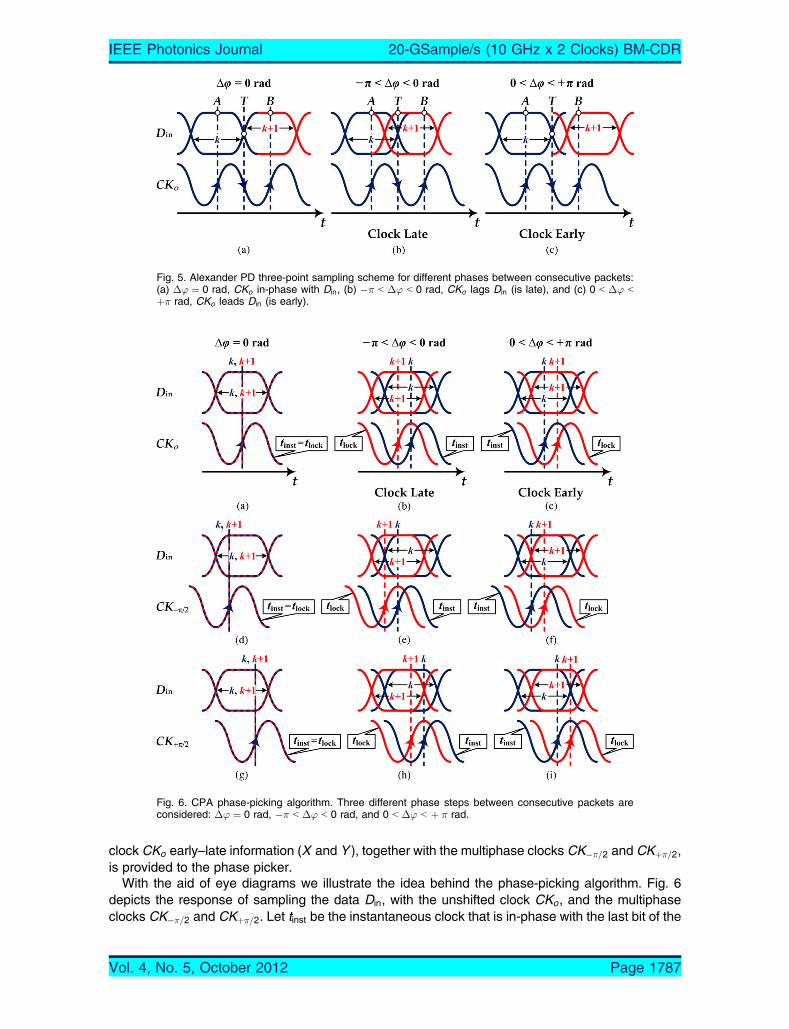
clock CKo early–late information (X and Y ), together with the multiphase clocks CK��=2 and CKþ�=2,is provided to the phase picker.
With the aid of eye diagrams we illustrate the idea behind the phase-picking algorithm. Fig. 6depicts the response of sampling the data Din, with the unshifted clock CKo, and the multiphaseclocks CK��=2 and CKþ�=2. Let tinst be the instantaneous clock that is in-phase with the last bit of the
Fig. 5. Alexander PD three-point sampling scheme for different phases between consecutive packets:(a) �’ ¼ 0 rad, CKo in-phase with Din, (b) �� G �’ G 0 rad, CKo lags Din (is late), and (c) 0 G �’ Gþ� rad, CKo leads Din (is early).
Fig. 6. CPA phase-picking algorithm. Three different phase steps between consecutive packets areconsidered: �’ ¼ 0 rad, �� G �’ G 0 rad, and 0 G �’ G þ � rad.
IEEE Photonics Journal 20-GSample/s (10 GHz x 2 Clocks) BM-CDR
Vol. 4, No. 5, October 2012 Page 1787

k th packet and out-of-phase by j�’j � 2� rad with the first bit of the ðk þ 1Þth packet. To achieveinstantaneous phase acquisition, the CPA must use the instantaneous clock tinst to correctly samplethe bits of the ðk þ 1Þth packet. Note, in the case of a conventional PLL-based CDR, its feedbackloop would need finite time to settle down and acquire lock; that is, align the instantaneous clock tinstto the lock state tlock so as to sample in the middle of the data bit.
When there is no phase difference between the consecutive packets �’ ¼ 0 rad, either of clocksCK��=2 orCKþ�=2 will correctly sample the data bits of the phase shifted ðk þ 1Þth packet [see Fig. 6(d)and (g)]. This is also true for an antiphase step �’ ¼ �� rad, (not shown in Fig. 6 because thescenario is similar to the 0-rad phase stepVamodulo-� process). For a phase step�� G �’ G 0 rad,clock CKo will lag the data [see Fig. 6(b)]; clock CKþ�=2 will sample the bits on or close to thetransitions of the data eye [see Fig. 6(h)] and thus corrupt the data. On the other hand, clock CK��=2will correctly sample the data [see Fig. 6(e)]. Similarly, for a phase step 0 G �’ G þ � rad, clock CKo
will lead the data [see Fig. 6(c)]; clock CK��=2 will sample the bits on or close to the transitions [seeFig. 6(f)], whereas clockCK��=2 will correctly sample the data [see Fig. 6(i)]. That is, regardless of anyphase step j�’j � 2� rad, there will be at least one sampling clock, either CK��=2 or CKþ�=2, that willyield an accurate sample. The phase picker then selects the most accurate sampling clock CKout,from these two possibilities for driving the D-FF to retime the data; that is, sample the noisy datayielding an outputDout, with less jitter. The foregoing concepts on the Alexander PD and phase pickerare summarized in Table 1, leading to the circuit topology in Fig. 4(b). The result is that the CPAachieves instantaneous phase acquisition (0 bit) for any phase step j�’j � 2� rad; that is, nopreamble bits ðl ¼ 0Þ at the beginning of the packet are necessary. Next, we provide an experimentaldemonstration for this, backed by a probabilistic theoretical prediction.
3. Results and DiscussionThe proposed BM-CDR is built from low cost/complexity commercial off-the-shelf (COTS)components rated at 13 Gb/s. It is built by integrating the following evaluation boards from HittiteMicrowave: XOR gate (HMC721LC3C), �-shifters (HMC538LP4), Alexander PD (HMC6032LC4B),AND gate (HMC722LC3C), 2:1 selector (HMC678LC3C), and D-FF (HMC723LC3C).
The BM-CDR is tested in a conventional BM test setup [9], [10]. Bursty traffic is generated froman Anritsu pattern generator by adjusting phase �’ in between packets or within a packet with aphase shifter. The packets are formed from guard bits, preamble bits, delimiter bits, 215 � 1pseudorandom binary sequence (PRBS) payload bits, and comma bits. The phase steps can be setbetween �125 ps with a 1-ps resolution, corresponding to a �1.25 unit interval (UI) at 10 Gb/s. Notethat 1 UI or 2� rad corresponds to 100 ps (1-bit period) at 10 Gb/s.
The plots in Fig. 7 depict the BER performance of a conventional CDR and the proposed BM-CDRat 10 Gb/s as a function of the phase step j�’j � 2� rad, between two consecutive data bits, for azero preamble length. For the CDR, we observe two bell-shaped curves centered at approximately�50 ps [see Fig. 7(a)]. As expected, these represent the half-bit periods corresponding to the worst-case phase steps at �’ ¼ �� rad, respectively. It follows that the CDR is sampling near the edge ofthe data eye, resulting in a loss of lock. At relatively small phase shifts (near) �’ 2 f0 rad;�2� radg,we can easily achieve error-free operation, BER G 10�10, because the CDR is almost sampling atthe middle of each data bit. For our BM-CDR, we achieve error-free operation for any phase stepj�’j � 2� rad with zero preamble bits allowing for instantaneous phase acquisition [see Fig. 7(a)].Additionally, we note that the BM-CDR can support up to 1000 CIDs with error-free operation. As the
TABLE 1
CPA (Alexander PD AND �-Picker) logic
IEEE Photonics Journal 20-GSample/s (10 GHz x 2 Clocks) BM-CDR
Vol. 4, No. 5, October 2012 Page 1788

length of the CIDs is increased to �2000 bits, the phase error between the successive bursts canaccumulate up to j�’ej ¼ � rad, resulting in a BER � 0:5.
At this point, it is interesting to compare the experimental results with probabilistic theoreticalpredictions to draw some important conclusions. The sampling error probability Ps of the CDR inpresence of phase steps j�’j � 2� rad and an l-bit preamble can be expressed as [12]
Psðj�’jÞ ¼12
Q�� j�’j � ð Þ 1� �ðlÞð Þ
2��ts ½UI
� �þQ
�þ j�’j � ð Þ 1� �ðlÞð Þ2��ts ½UI
� �� �(2)
where QðÞ, called the BQ function,[ is the normalized Gaussian-tail probability defined as
QðxÞ ¼� 1ffiffiffiffiffiffi2�p
Z1x
exp ��2
2
� �d� (3)
where �ts is the root mean square (RMS) jitter on the sampling clock in UI, is the correcting factorintroduced to account for the symmetrical performance about the edges of the data bit at �Tb=2 andþTb=2 as
¼ 0; if j�’j � � rad2�; if � G j�’j � 2� rad
�(4)
and �ðlÞ measures the CDR’s lock acquisition time, analytically derived to be [16]
�ðlÞ ¼ 1� expð�l�!nTbÞ � coshðl!nTb
ffiffiffiffiffiffiffiffiffiffiffiffiffi�2 � 1
pÞ � �ffiffiffiffiffiffiffiffiffiffiffiffiffi
�2 � 1p sinhðl!nTb
ffiffiffiffiffiffiffiffiffiffiffiffiffi�2 � 1
pÞ
( )(5)
where � 9 0 is the Bdamping ratio[ and !n in radians per second is the Bnatural frequency,[ bothbeing functions of the CDR circuit parameters [16].
Moving forward, the Alexander PD’s probability of correctly determining an early or late clock CKo
can be written as
PrðCKoÞ ¼ PrðAÞ � PrðBÞ � PrðT Þ (6)
and the probabilities of correctly sampling points A, B, and T can be given as:
PrðAÞ ¼PrðBÞ � 1� Ps j�’jð Þ½ (7)
PrðBÞ ¼ 1� Ps j�’jð Þ (8)
PrðT Þ ¼ 1� # Ps j�’j � �ð Þ þ Ps j�’j þ �ð Þ½ f g � 1� Ps j�’jð Þ½ (9)
Fig. 7. BER performance versus phase step for a zero preamble length (solid lines for experimentalcurves; dashed line from theoretical predictions). (a) Conventional CDR. (b) Proposed BM-CDR.
IEEE Photonics Journal 20-GSample/s (10 GHz x 2 Clocks) BM-CDR
Vol. 4, No. 5, October 2012 Page 1789
where Psðj�’jÞ ¼ Psðj�’j; l ¼ 0Þ sampling error probability of a bit, and # is another correctingfactor introduced to account for the symmetrical performance about the edges of the data bit as
# ¼12 ; if j�’j � � rad1; if � G j�’j � 2� rad.
�(10)
The sampling points of the multiphase clocks CK��=2 or CKþ�=2 are located at tk 2 f��=2;þ�=2g,respectively, about the center of the data eye. The sampling error probabilities Pk
s of the multiphaseclocks can be calculated by convolving Psðj�’jÞ in (2), with the sampling points tk , as
Pks ¼ Ps j�’jð Þ � � j�’j � tkð Þ (11)
where
� j�’j � tkð Þ ¼� 1; if j�’j ¼ tk0; if j�’j 6¼ tk
�(12)
is the Dirac-delta function. It follows from the sifting property
Pks ¼
Zþ1�1
Ps j�’j � �ð Þ�ð�� tk Þd� ¼ Ps j�’j � tkð Þ:
The phase-picking algorithm determines the clock sample CK��=2 or CKþ�=2, closest to the centerof the data eye upon detecting an early or late clock CKo, with respect to data Din. Consequently,the sampling error probability of the BM-CDR PBM�CDR
s can be expressed as
PBM�CDRs ¼ PrðCKoÞ �min Ps j�’j � tkð Þf g: (13)
Finally, we define the BER, denoted as Pe, of the CDR and BM-CDR, from the sampling errorprobabilities in (2) and (13), respectively, as follows:
BER � Pe ¼� Ps j�’jð Þ; for PLL-based CDR
PBM�CDRs ; for BM-CDR.
�(14)
We compare the experimental results with the theoretical predictions for the CDR and the BM-CDR from (2) and (13) in Fig. 7(a) and (b), respectively. For BER G 10�6, the results are in closeagreement. However, for the CDR, the theoretical bound is optimistic for BER 9 10�6 as theprobabilistic model accounts for the jitter input to the receiver and not for jitter generated by the
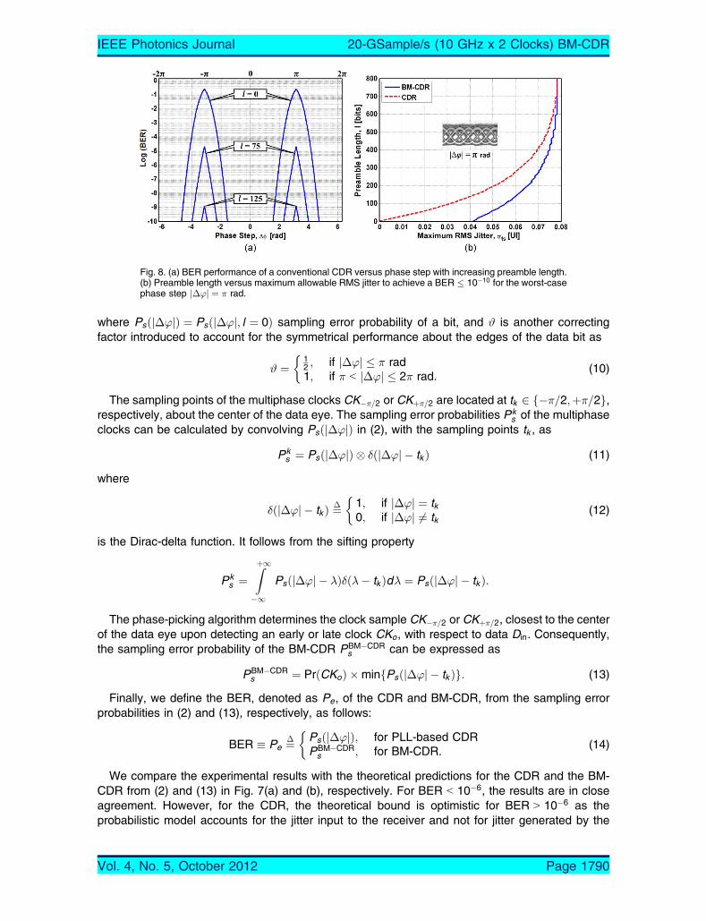
Fig. 8. (a) BER performance of a conventional CDR versus phase step with increasing preamble length.(b) Preamble length versus maximum allowable RMS jitter to achieve a BER � 10�10 for the worst-casephase step j�’j ¼ � rad.
IEEE Photonics Journal 20-GSample/s (10 GHz x 2 Clocks) BM-CDR
Vol. 4, No. 5, October 2012 Page 1790

circuitry. This may be a result of VCO phase noise in the CDR and data bits being asymmetric withdifferent rise and fall times leading to different jitter distribution on the edges of the data eye.
To measure the phase acquisition time of the CDR, preamble bits (B1010 . . .[ pattern) can beinserted at the beginning of the packet to help the PLL of the CDR to settle down and acquire lockuntil error-free operation is achieved. In Fig. 8(a), as the preamble length is increased, there is animprovement in the BER. After 125 preamble bits, we perceive error-free operation for any phasestep. However, the use of a preamble introduces overhead, reducing the effective throughput andincreasing delay.
To compare the jitter tolerance of the CDR with the proposed BM-CDR, examine the plots inFig. 8(b), which show the number of preamble bits required to obtain a BER � 10�10 as a function ofthe maximum allowable RMS jitter for the worst-case phase step j�’j ¼ � rad. Our BM-CDR is ableto achieve instantaneous phase acquisition ðl ¼ 0Þ when the RMS jitter �ts � 0:04 UI. This is truefor any phase step j�’j ¼ 2� rad, as shown in Fig. 7(b). This is not the case for the CDR as thetolerance to jitter is 0 UI to obtain instantaneous phase acquisition for the worst-case phase step.This implies that it is not feasible for the CDR to obtain instantaneous phase acquisition since ajitter-free sampling clock is practically impossible. These theoretical limits can be summarized as:
liml!0�maxts ¼ 0 UI; for CDR
0:04 UI; for BM-CDR
�forj�’j ¼ � rad: (15)
With increasing preamble length, the jitter tolerance of the CDR and BM-CDR on the samplingclock increases for a given phase step. It tends to become independent of the phase step in thepresence of a large number of preamble bits
liml!1�maxts ¼ 0:08 UI; for all j�’j � 2� rad: (16)
In Fig. 9, we plot the BER performance of the CDR and BM-CDR as a function of phase steps fordifferent RMS jitter and zero preamble bits. When the RMS jitter is �ts 9 0:04 UI, the shaded area inFig. 9(a) depicts the tradeoff region with the phase steps j�’j � �=4 rad, where the CDR has abetter jitter tolerance than the BM-CDR. This is expected as the CDR’s recovered clock is samplingcloser to the middle of the data bit compared with the BM-CDR’s multiphase clocks, which aresampling further away from the center of the data eye for phase steps j�’j � �=4 rad (see Fig. 6).However, for phase steps �=4 G j�’j � � rad, the BM-CDR has a better jitter tolerance.Furthermore, Fig. 9(b) shows that, while the BM-CDR achieves instantaneous phase acquisitionfor any phase step j�’j � 2� rad when the RMS jitter �ts � 0:04 UI, the CDR performancedegrades with increasing RMS jitter.
Fig. 9. BER performance of the BM-CDR and CDR versus phase step for different RMS jitter andzero preamble bits. (a) �ts 9 0:04 UI depicting the tradeoff region in the range j�’j � �=4 rad.(b) �ts � 0:04 UI.
IEEE Photonics Journal 20-GSample/s (10 GHz x 2 Clocks) BM-CDR
Vol. 4, No. 5, October 2012 Page 1791
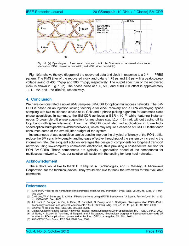
Fig. 10(a) shows the eye diagram of the recovered data and clock in response to a 215 � 1 PRBSpattern. The RMS jitter of the recovered clock and data is 1.75 ps and 2.5 ps with a peak-to-peakvoltage swing of 435 mVp-p and 300 mVp-p, respectively. The output spectrum of the recoveredclock is shown in Fig. 10(b). The phase noise at 100, 500, and 1000 kHz offset is approximately�24, �62, and �68 dBc/Hz, respectively.
4. ConclusionWe have demonstrated a novel 20-GSample/s BM-CDR for optical multiaccess networks. The BM-CDR is based on an injection-locking technique for clock recovery and a CPA employing spacesampling with two multiphase clocks at 10 GHz and a phase-picking algorithm for automatic clockphase acquisition. In summary, the BM-CDR achieves a BER G 10�10 while featuring instanta-neous (0 preamble bit) phase acquisition for any phase step j�’j � 2� rad, without trading off itsloop bandwidth (jitter tolerance). Thus, the BM-CDR could also find applications in future high-speed optical burst/packet switched networks, which may require a cascade of BM-CDRs that eachconsumes some of the overall jitter budget of the system.
Instantaneous phase acquisition can be used to improve the physical efficiency of the PON traffic,reduce the BM sensitivity penalty, and increase effective throughput of the system by increasing theinformation rate. Our eloquent solution leverages the design of components for long-haul transportnetworks using low-complexity commercial electronics, thus providing a cost-effective solution forPON BM-CDRs. These components are typically a generation ahead of the components formultiaccess networks. Thus, our solution will scale with the scaling for long-haul networks.
AcknowledgmentThe authors would like to thank R. Karlquist, A. Technologies, and B. Massey, H. Microwave
Corporation, for the technical advice. They would also like to thank the reviewers for their valuablecomments.
References[1] T. Koonen, BFiber to the home/fiber to the premises: What, where, and when,[ Proc. IEEE, vol. 94, no. 5, pp. 911–934,
May 2006.[2] C.-H. Lee, W. V. Sorin, and B. Y. Kim, BFiber to the home using a PON infrastructure,[ J. Lightw. Technol., vol. 24, no. 12,
pp. 4568–4583, Dec. 2006.[3] J.-I. Kani, F. Bourgart, A. Cui, A. Rafel, M. Campbell, R. Davey, and S. Rodrigues, BNext-generation PONVPart I:
Technology roadmap and general requirements,[ IEEE Commun. Mag., vol. 47, no. 11, pp. 43–49, Nov. 2009.[4] Ethernet in the First Mile, IEEE Std. 802.3ah, 2004.[5] Gigabit-Capable Passive Optical Networks: Physical Media Dependent Layer Specification, ITU-T Std. G.984.2, 2003.[6] M. Noda, N. Suzuki, S. Yoshima, M. Nogami, and J. Nakagawa, BTechnology progress of high-speed burst-mode 3R
receiver for PON applications,[ presented at the Proc. OFC, Los Angeles, CA, Mar. 2012.[7] 10G-EPON Task Force, IEEE Std. P802.3av, 2009.
Fig. 10. (a) Eye diagram of recovered data and clock. (b) Spectrum of recovered clock (Atten:attenuation; RBW: resolution bandwidth; and VBW: video bandwidth).
IEEE Photonics Journal 20-GSample/s (10 GHz x 2 Clocks) BM-CDR
Vol. 4, No. 5, October 2012 Page 1792
[8] T. Ito, T. Kurosaki, M. Nakamura, S. Nishihara, Y. Ohtomo, A. Okada, and M. Yoneyama, BA burst-mode APD-ROSAusing reset signal with less than 100 ns response for 1G/10G-EPON dual-rate optical transceivers,[ J. Lightw. Technol.,vol. 29, no. 14, pp. 2089–2101, Jul. 2011.
[9] J. Nakagawa, M. Nogami, N. Suzuki, M. Noda, S. Yoshima, and H. Tagami, B10.3-Gb/s burst-mode 3R receiverincorporating full AGC optical receiver and 82.5-GS/s over-sampling CDR for 10G-EPON systems,[ IEEE Photon.Technol. Lett., vol. 22, no. 7, pp. 471–473, Apr. 2010.
[10] A. Li, J. Faucher, and D. V. Plant, BBurst-mode clock and data recovery in optical multiaccess networks using broad-band PLLs,[ IEEE Photon. Technol. Lett., vol. 18, no. 1, pp. 73–75, Jan. 2006.
[11] J. Terada, K. Nishimura, S. Kimura, H. Katsurai, N. Yoshimoto, and Y. Ohtomo, BA 10.3 Gb/s burst-mode CDR using a�� DAC,[ IEEE J. Solid-State Circuits, vol. 43, no. 12, pp. 2921–2928, Dec. 2008.
[12] B. J. Shastri and D. V. Plant, B5/10-Gb/s burst-mode clock and data recovery based on semiblind oversamplingfor PONs: Theoretical and experimental,[ IEEE J. Sel. Topics Quantum Electron., vol. 16, no. 5, pp. 1298–1320,Sep./Oct. 2010.
[13] B. J. Shastri, Y.-B. M’Sallem, N. Zicha, L. A. Rusch, S. LaRochelle, and D. V. Plant, BAn experimental study of burst-mode reception in a 1300-km deployed fiber link,[ IEEE/OSA J. Opt. Commun. Netw., vol. 2, no. 1, pp. 1–9, Jan. 2010.
[14] B. J. Shastri, Z. A. El-Sahn, M. Zeng, N. Kheder, D. V. Plant, and L. A. Rusch, BA standalone burst-mode receiver withclock and data recovery, clock phase alignment, and RS(255,239) codes for SAC-OCDMA applications,[ IEEE Photon.Technol. Lett., vol. 20, no. 5, pp. 363–365, Mar. 2008.
[15] B. J. Shastri and D. V. Plant, BTruly modular burst-mode CDR with instantaneous phase acquisition for multiaccessnetworks,[ IEEE Photon. Technol. Lett., vol. 24, no. 2, pp. 134–136, Jan. 2012.
[16] B. Razavi, Design of Integrated Circuits for Optical Communication Systems. New York: McGraw-Hill, 2003.[17] J.-H. C. Zhan, J. S. Duster, and K. T. Kornegay, BFull-rate injection-locked 10.3 Gb/s clock and data recovery circuit in a
45 GHz-fT SiGe process,[ in Proc. IEEE CICC, Sep. 2005, pp. 552–557.[18] J. D. H. Alexander, BClock recovery from random binary data,[ Electron. Lett., vol. 11, no. 22, pp. 541–542, Oct. 1975.
IEEE Photonics Journal 20-GSample/s (10 GHz x 2 Clocks) BM-CDR
Vol. 4, No. 5, October 2012 Page 1793