Embed Size (px)
Citation preview

1 | P a g e
Advances in Shell Room with quick setting polymer additive for ceramic back up slurries
Gavin Dooley1., Matt Cavins2 ,Manuel Guerra3 , Matthew Everden1
1.REMET UK, Ltd., 2. O’Fallon Casting, 3.REMET PIC Inc.
Submitted to
Investment Casting Institute
Topic Area: Process Improvement - Shell
Abstract
REMET has formulated the industry’s first quick setting polymer which confers the
advantage of fast drying whilst maintaining reliable and convenient slurry characteristics
and maintenance. In order to quantify the performance and operating mechanism of the
polymer, a series of experiments have been carried out to compare the new formulation
with one of REMET’s most popular traditional enhancement polymers. Measurement of
the modulus of a the new enhanced slurry and a traditional slurry by DMA during drying
has enabled the gelation points of each system to be accurately determined.
Measurement of temperature drop during drying has been used to compare the facility of
water evaporation from the quick drying slurry and traditional slurry under identical
conditions. The results confirm that not only is the quick drying polymer system faster to
gel, but that the rate of water evaporation is unimpeded by the gelation process.
O’Fallon Casting is using this polymer and a colloidal silica binder in an experimental
capacity for the replacement of an ethyl silicate slurry system. The application of ammonia
vapors to an ethyl silicate shell layer induces a quick gelling of the binder, offering control
of the drying process. Traditional polymer systems have failed to support the conversion
to a colloidal silica binder while preserving the low viscosity range achievable with ethyl
silicate. New formulations using the novel polymer concentrate have performed
2 | P a g e
successfully in achieving two principle qualities of an alcohol slurry system: a rapid gelling
time, and a reduced cold strength for ease of knockout. A case study is presented here
to demonstrate the development of a trial slurry recipe at O’Fallon Casting using the quick
drying polymer, and the iterative progression of the formula through MOR testing and the
reduction of shell-related casting defects.

3 | P a g e
Introduction
With increasing demands on the Investment Casting industries to reduce lead time by
novel technologies including Additive Manufacturing, there have been many attempts to
reduce the lead time through the shell room. These have been met with limited success
and are summarized below.
Remet set out to product a novel material which would reduce lead times while
maintaining or improving the strength of the shell system. QUIKSET™, a novel polymer
concentration was introduced and tested.
Background
Polymer science has gone from strength to strength since the introduction of polymers to
shell systems. The addition of the polymer affects the green strength of the shell during
drying and autoclave de-wax while also improving dry time. Following burnout, the
polymer is no longer present which creates voids, weakening the shell to allow for easier
knockout. While cooled, the shell exhibits similar strengths to a shell system with no
polymer, allowing for easy shell removal. This can be seen within figure 1 below.

4 | P a g e
Figure 1 Development of strength with different generations of polymer
With this increase in strength, issues of BoilerClave cracking and drying defects are
greatly reduced. However, the drying times are still quite long and delay processing of
components within the process. Within this paper we will present AdBond® Quickset ™
polymer concentrate technology which greatly reduces dry time without the need for
infrastructure or modified dipping programs.
Fundamentals of drying
There are two ways of drying a colloidal silica sol, one is through the change in pH toward
pH 7 as indicated in Figure 2.
0
0.2
0.4
0.6
0.8
1
1.2
1.4
1.6
1.8
2
No polymer 1st Generation 2nd Generation
Rel
ativ
e St
ren
gth
sDEVELOPMENT OF STRENGTH WITH DIFFERENT GENERATIONS OF
POLYMER
Green Hot Cold

5 | P a g e
Figure 2 Gel time as a function of pH
The second mechanism is through the removal of the water, which brings the silica
particles together to gel the sol and create a solid matrix. This solid matrix then stiffens
and creates bonding of the ceramic.
Within a shell system, it is difficult altering the pH, as the slurry life will shorten and cause
instabilities within the process. Increasing the water removal rate has been attempted
through many methods. These include:
1. Rapid Air Drying – High speed air drying system technology have been introduced
to increase the water removal rates [1]. The infrared technology utilizes rapid removal
of water while counteracting the temperature drop of the wax by infrared light to
maintain dimensional stability.
2. Microwave drying - Microwave drying has been utilized to remove water from the
shell [2]. This system allows reports it can control drying conditions to affect the
mechanical properties of the shell.
3. Rapid Shell Drying – Rapid Shell Drying has utilized the use of Super Absorbent
Polymers to reduce drying times by pulling the water from the sol and storing it within

6 | P a g e
the absorbent polymer. There are drawbacks to this method, including a reduction in
strength of the ceramic [3].
4. Desiccant based systems – These systems used a silica gel to remove water from
the shell system and into the stucco layer [4]. Again, the drawback of these methods
is the retention of water within the shell during drying.
Within items 1 & 2 mentioned above, significant capital investment is required. These can
be unfeasible for many foundries. For items 3&4 the retention of water within the shell
can reduce the strength of the shell and be susceptible to cracking and bulging during
firing.
Remet has formulated an innovative AdBond® QUIKSET™(QS) technology to accelerate
removal of water from the shell to ensure no water is trapped within the matrix during re-
dipping. Using a proprietary polymer combination, it allows for the gelation of the slurry
but also keeps a path free for water to travel to the surface of the mould and be removed
during drying. This can be seen visually within Figure 3 Simplified gelation of slurry within
a shell system.
(a)
(b)
(c)
Figure 3 Simplified gelation of slurry within a shell system (a) ungelled slurry (b) gelation of traditional polymer shells (c) Gelation of QuikSet Slurry
7 | P a g e
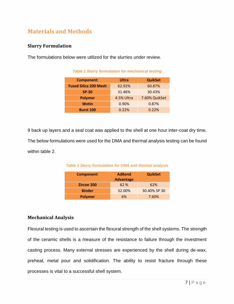
Materials and Methods
Slurry Formulation
The formulations below were utilized for the slurries under review.
Table 1 Slurry formulation for mechanical testing
Component: Ultra QuikSet
Fused Silica 200 Mesh 62.92% 60.87%
SP-30 31.46% 30.43%
Polymer 4.5% Ultra 7.60% QuikSet
Wetin 0.90% 0.87%
Burst 100 0.22% 0.22%
9 back up layers and a seal coat was applied to the shell at one hour inter-coat dry time.
The below formulations were used for the DMA and thermal analysis testing can be found
within table 2.
Table 2 Slurry formulation for DMA and thermal analysis
Component: AdBond Advantage
QuikSet
Zircon 200 62 % 62%
Binder 32.00% 30.40% SP 30
Polymer 6% 7.60%
Mechanical Analysis
Flexural testing is used to ascertain the flexural strength of the shell systems. The strength
of the ceramic shells is a measure of the resistance to failure through the investment
casting process. Many external stresses are experienced by the shell during de-wax,
preheat, metal pour and solidification. The ability to resist fracture through these
processes is vital to a successful shell system.
8 | P a g e
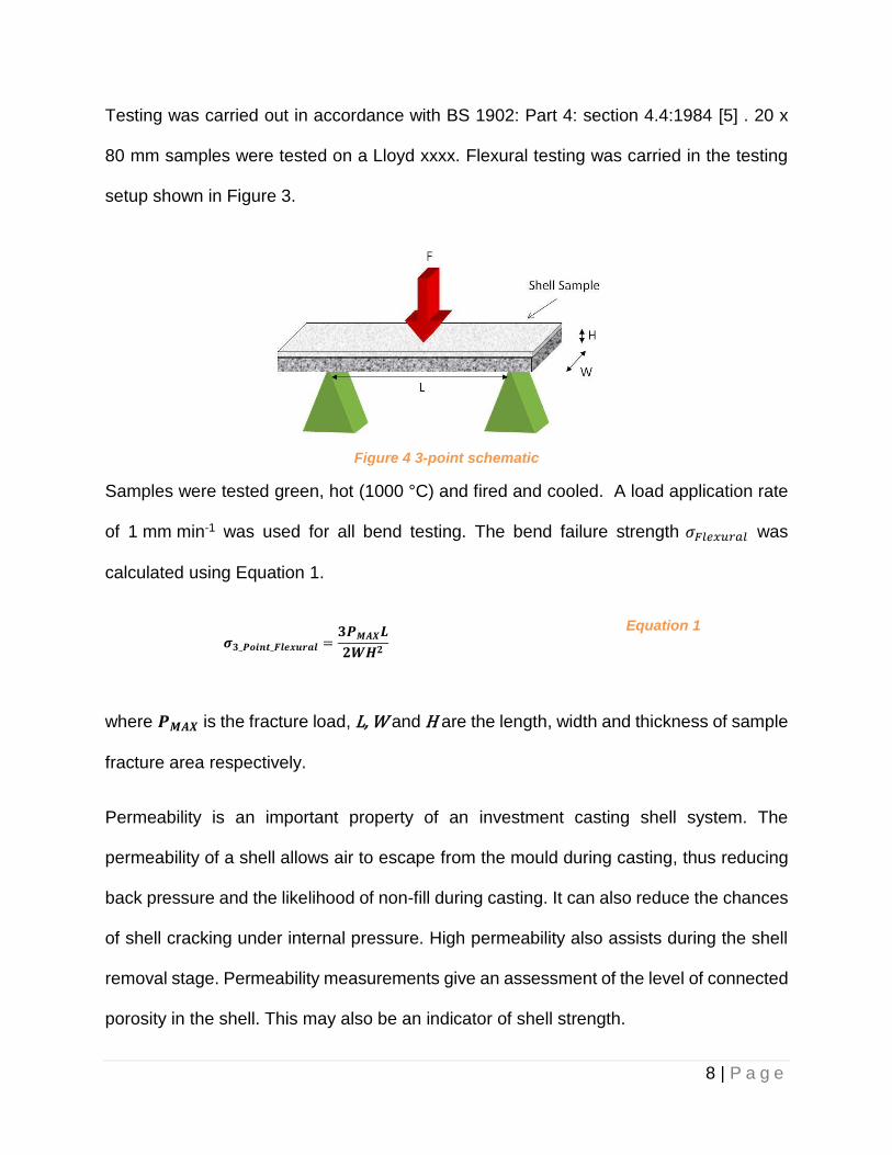
Testing was carried out in accordance with BS 1902: Part 4: section 4.4:1984 [5] . 20 x
80 mm samples were tested on a Lloyd xxxx. Flexural testing was carried in the testing
setup shown in Figure 3.
Figure 4 3-point schematic
Samples were tested green, hot (1000 °C) and fired and cooled. A load application rate
of 1 mm min-1 was used for all bend testing. The bend failure strength 𝜎𝐹𝑙𝑒𝑥𝑢𝑟𝑎𝑙 was
calculated using Equation 1.
𝝈𝟑_𝑷𝒐𝒊𝒏𝒕_𝑭𝒍𝒆𝒙𝒖𝒓𝒂𝒍 =𝟑𝑷𝑴𝑨𝑿𝑳
𝟐𝑾𝑯𝟐
Equation 1
where 𝑷𝑴𝑨𝑿 is the fracture load, L, W and H are the length, width and thickness of sample
fracture area respectively.
Permeability is an important property of an investment casting shell system. The
permeability of a shell allows air to escape from the mould during casting, thus reducing
back pressure and the likelihood of non-fill during casting. It can also reduce the chances
of shell cracking under internal pressure. High permeability also assists during the shell
removal stage. Permeability measurements give an assessment of the level of connected
porosity in the shell. This may also be an indicator of shell strength.

9 | P a g e
Tests were performed in accordance with BS 1902: Section 10.2:1994. Test pieces were
made using “International Table Tennis Federation (ITTF) approved 3 star table tennis
balls and impervious mullite (Si4Al6O13) rods” at a temperature of 1000°C [6].
Figure 5 Permeability Sample with and without ping pong ball
Permeability measurements were taken at time intervals up to one hour to assess the
effect of sintering on the samples analysed. Equation 2 was used to determine the
permeability of the samples:
𝝁 =
𝒔𝑽𝒄𝜼
𝒂∆𝑷
Equation 2
where µ is the permeability, s is the wall thickness of the sample, Vc is the volumetric flow
rate, 𝜼 is the dynamic viscosity of air at the elevated temperature, 𝒂 is the inner surface
area of the tennis ball and ΔP is the pressure difference.
Dynamic Mechanical Analysis
Dynamic Mechanical Analysis (DMA) is a mechanical method of analyzing material
properties while under a dynamic response. This cutting edge testing can analyse the
expansion and contraction of waxes, the dynamic loading of a wax at different
temperatures, and also the gelation of slurry.

10 | P a g e
A defined volume of slurry was thinly coated on a rubber sample, this sample was then
oscillated at a constant deflection to assess the force required to stress the sample. A
control sample of slurry was compared to the new QuikSet ™ slurry at constant
temperature and humidity settings.
(a)
(b) (c) Figure 6 DMA Setup to assess gelation of slurries. (a) Testing Schematic (b) Test Rig (c)
Samples within sample holder
Infrared Image Analysis
The temperature difference between the two slurries was also calculated using thermal
imaging. Samples of the same volume were place in a defined wax substrate to mimic
drying on a wax pattern. The samples were placed in a controlled temperature and
humidity environment with low air flow rate.

11 | P a g e
A video was captured using a micro epsilon thermo imager and a single point on each
sample was logged for temperature over time. This data was then inputted into excel to
give a relationship of temperature over time.
(a)
(b) (c) Figure 7 Thermal imaging camera setup (a) Testing schematic (b) Test setup (c) IR image
captured of the slurries drying
Results & Discussion
Mechanical Analysis
The flexural strength results for the samples can be found within Figure 8.

12 | P a g e
Figure 8 Flexural Strength (MOR) of Ultra vs. QuikSet slurries [N=4]
The permeability results can be found in Figure 9.
Figure 9 Permeability of Ultra Vs. QuikSet materials using the ping pong method [n=3]
13 | P a g e
The mechanical testing shows the strength of the QuickSet slurry is 49 % stronger in the
green strength with a 22 % increase while hot. This increase in strength then drops to
comparable values when fired and cooled, allowing for easy knock out.
Even with this increase in strength, there is also an increase in permeability by 46 %. This
is due to a high polymer content within the system opening voids and improving air flow
through the shell.
Thermal Analysis
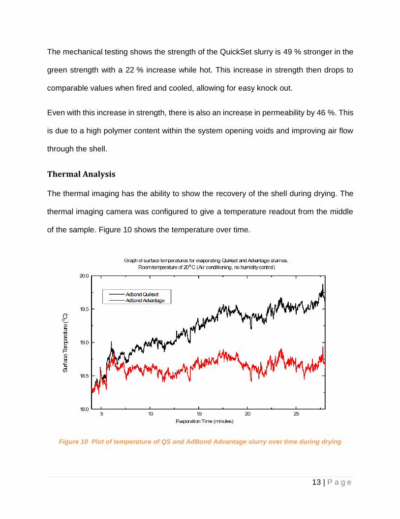
The thermal imaging has the ability to show the recovery of the shell during drying. The
thermal imaging camera was configured to give a temperature readout from the middle
of the sample. Figure 10 shows the temperature over time.
Figure 10 Plot of temperature of QS and AdBond Advantage slurry over time during drying
14 | P a g e
As can be seen within this graph, the QS slurry has recovered temperature much quicker
than the traditional slurry. After 30 minutes, there was over a 1 °C difference in
temperature between both slurries. This indicates that the QS slurry is drying quicker and
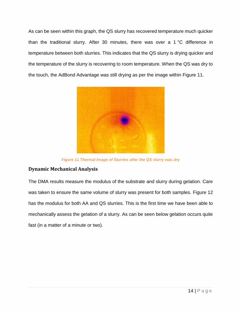
the temperature of the slurry is recovering to room temperature. When the QS was dry to
the touch, the AdBond Advantage was still drying as per the image within Figure 11.
Figure 11 Thermal Image of Slurries after the QS slurry was dry
Dynamic Mechanical Analysis
The DMA results measure the modulus of the substrate and slurry during gelation. Care
was taken to ensure the same volume of slurry was present for both samples. Figure 12
has the modulus for both AA and QS slurries. This is the first time we have been able to
mechanically assess the gelation of a slurry. As can be seen below gelation occurs quite
fast (in a matter of a minute or two).

15 | P a g e
Figure 12 Plot of modulus vs. Evaporation time AA Slurry vs. QS slurry
The DMA results show the slow increase in modulus within the AA slurry sample as it
slowly dries during testing. This then follows the sharp increase in modulus during
gelation.
For QS, the gelation of the sol happens much quicker than with AA slurries due to the
novel polymer present within the shell matrix. The onset of gelation occurs much quicker
(71% quicker!) than the standard sol. Following gelation, there is still some increase in
modulus as the slurry continues to dry.
16 | P a g e
Shell Trial
A shell trial was conducted within O’Fallon Casting to assess the feasibility of transferring
from Ethyl Silicate (ES) shell system, to the QS shell system. O’Fallon Casting uses the
ES system as an intermediate slurry for 3 to 5 layers between a single prime and backups.
The ES system provides improved shell drying by using ammonia gelling. With this in
mind, one of the main objective of the trial was to produce complex investment castings
using QS but maintaining the same dry times as used for the ES system. In addition, the
ease of knockout was critical to a successful trial. Improvements in one area of the plant
cannot be successful if it reduces efficiency down the line. The final objective was to
maintain similar dimensional results.
Initially, the slurry formulation was based on the current ES system. O’Fallon Casting
uses mullite flour for the ES. To assist in maintaining dimensional results, it was also used
in the trial slurry. The % solids and viscosity were kept constant, the % silica was
controlled at 21%. Viscosity was measured using a #3 Zahn and silica was determined
using density. The trial was conducted on multiple parts with a variety of complexity.
Beginning the trial, parts were hand dipped; but as the trial progressed, robot dipping was
utilized. In both cases, the same dry time and same environmental conditions (68-72F
and 55-65% RH) as the ethyl silicate system were maintained. The samples were
autoclaved and fired to 1450 °F for 1 hour, then pre-heated to part dependant mold temps.
Parts were poured using A 356 aluminum, A 357 aluminum and aluminum matrix silicon
carbide composites. Positive results occurred initially showing good surface finish without
cracking or other shell related defects.
17 | P a g e
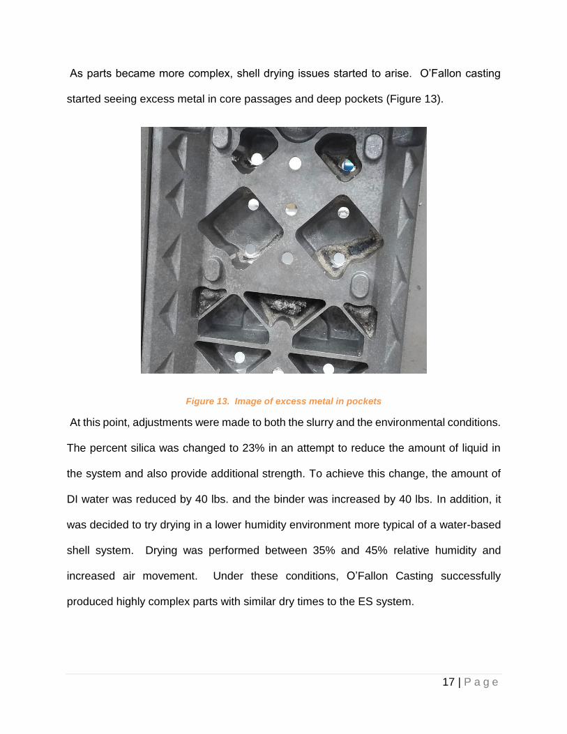
As parts became more complex, shell drying issues started to arise. O’Fallon casting
started seeing excess metal in core passages and deep pockets (Figure 13).
Figure 13. Image of excess metal in pockets
At this point, adjustments were made to both the slurry and the environmental conditions.
The percent silica was changed to 23% in an attempt to reduce the amount of liquid in
the system and also provide additional strength. To achieve this change, the amount of
DI water was reduced by 40 lbs. and the binder was increased by 40 lbs. In addition, it
was decided to try drying in a lower humidity environment more typical of a water-based
shell system. Drying was performed between 35% and 45% relative humidity and
increased air movement. Under these conditions, O’Fallon Casting successfully
produced highly complex parts with similar dry times to the ES system.
18 | P a g e
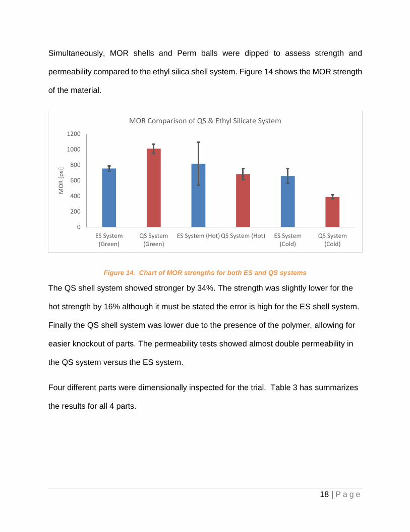
Simultaneously, MOR shells and Perm balls were dipped to assess strength and
permeability compared to the ethyl silica shell system. Figure 14 shows the MOR strength
of the material.
Figure 14. Chart of MOR strengths for both ES and QS systems
The QS shell system showed stronger by 34%. The strength was slightly lower for the
hot strength by 16% although it must be stated the error is high for the ES shell system.
Finally the QS shell system was lower due to the presence of the polymer, allowing for
easier knockout of parts. The permeability tests showed almost double permeability in
the QS system versus the ES system.
Four different parts were dimensionally inspected for the trial. Table 3 has summarizes
the results for all 4 parts.
0
200
400
600
800
1000
1200
ES System(Green)
QS System(Green)
ES System (Hot) QS System (Hot) ES System(Cold)
QS System(Cold)
MO
R [
psi
]
MOR Comparison of QS & Ethyl Silicate System

19 | P a g e
Table 3. Dimensional results of trial parts
Part # Drawing Dimension with tolerence (inch)
ES Dimension (inch)
QS Dimension (inch)
Change from ES to QS (inch)
1 0.720 ± 0.020 0.7220 0.7228 0.0007
2 1.50 ± 0.015 1.4995 1.5034 0.0039
2 3.78 ± 0.020 3.7841 3.7785 -0.0056
3 13.31 ± 0.075 13.3434 13.3503 0.0068
4 1.590 ± 0.010 1.5950 1.5955 0.0005
4 0.630 ± .010 0.6279 0.6310 0.0031
4 1.380 ± .010 1.3742 1.3785 0.0043
All measurements for all parts fell within the dimensional tolerance allowed by the
drawings and a few dimensions had almost no change between the 2 shell systems.
However, several of the dimensions showed a significant difference between the ES and
QS system. More dimensional testing is needed on a larger sample set to determine the
exact impact of the QS system.
Conclusion
Remet has developed the use of DMA to assess the gelation of slurries. The increase in
modulus of a slurry can be seen when an oscillating load is applied to an elastic rubber
substrate with an applied slurry material.
QuikSet™ Polymer Concentrate can offer significant advances in shell room building with
no requirement for capital investment. When compared to current slurries on the markets,
QS can reduce dry times, occurrences of cracks and defects and improve permeability of
the shell during casting. The QS polymer can ensure temperature and humidity deviations
do not result in scrap and yield issues.

20 | P a g e
The trials conducted at O’Fallon Casting showed that QS can be used to replace ES, but
will require conversion to a lower relative humidity with increased air movement. The
presence of the polymer within the shell also works to reduce the cold strength allowing
for better knock off. It has been found over the years that there have been some
dimensional differences noted between ethyl silicate and water-based binder systems,
even using the same refractory. Some speculate that the differences in sodium content
of the binders plays a large part in this
References
[1] M. Kugelen, Latest Developments and Trends for Ceramic Shell Building with Water
Based Slurries, in 13th World Conference on Investment Casting. 2012: Kyoto, Japan.
[2] N. Chida, Microwave Drying Furnace Drying the Complex Shaped Molds in Short
Time, in 60th ICI Technical Conference. 2013: Pittsburgh, PN.
[3] G. Dooley, Characterisation Of Rapid Shell Manufacturing System For Improved Lead
Times In The Manufacture Of Investment Cast Parts. 2012: Nashville, TN.
[4] E E Hellstrom and D S Mc Guire, A New Generation of Stucco Mixtures to Build Shells
Rapidly in 57th ICI Technical Conference. 2010: Dearborn
[5] BSI, Methods of test for Dense shaped refractory products - Part 6: Determination of
modulus of rupture at ambient temperature, in BS EN 993-6:1995 BS 1902-4.4: 1995.
1995.
[6] BSI, Methods of testing Refractory materials - Part 10: Investment casting shell mould
systems — Section 10.2: Determination of permeability and standard air flow capacity at
elevated temperatures, in BS 1902-10.2:1994. 1994.