Embed Size (px)
Citation preview
HAL Id: hal-00824272https://hal.archives-ouvertes.fr/hal-00824272
Submitted on 21 May 2013
HAL is a multi-disciplinary open accessarchive for the deposit and dissemination of sci-entific research documents, whether they are pub-lished or not. The documents may come fromteaching and research institutions in France orabroad, or from public or private research centers.
L’archive ouverte pluridisciplinaire HAL, estdestinée au dépôt et à la diffusion de documentsscientifiques de niveau recherche, publiés ou non,émanant des établissements d’enseignement et derecherche français ou étrangers, des laboratoirespublics ou privés.
Investigations on the critical speed suppressing by usingelectromagnetic actuatorsJarir Mahfoud, Johan Der Hagopian
To cite this version:Jarir Mahfoud, Johan Der Hagopian. Investigations on the critical speed suppressing by using elec-tromagnetic actuators. Smart Structures and Systems, Korea : Techno-Press, 2012, 9 (4), pp.303-311.�hal-00824272�

1
Investigations on the critical speed suppressing by using
electromagnetic actuators
Jarir Mahfoud1* and Johan Der Hagopian1
1 Université de Lyon - Laboratoire de Mécanique des Contacts et des Structures - UMR CNRS 5259,
Institut National des Sciences Appliquées de Lyon, FRANCE.
Abstract
The possibility of suppressing critical speeds by using electromagnetic actuators (EMAs) is
assessed experimentally in this paper. The system studied is composed of a horizontal
flexible shaft supported by two ball bearings at one end and one roller bearing that is located
in a squirrel cage at the other end. Four identical EMAs supplied with constant current are
utilized. The EMAs associated to the squirrel cage constitutes the hybrid bearing. Results
obtained, show that the constant current, when applied to the EMAs, produces a shift of the
first critical speed toward lower values. Moreover, the application of constant current for a
speed interval around the critical speed enables a smooth run-up or run-down without
crossing any resonance.
Keywords:
Critical speeds, Electromagnetic actuators, Rotordynamics, Hybrid bearings, Experiments.
*Corresponding author. Associate Professor, E-mail: [email protected]
2
1. Introduction
Modern rotating machinery becomes lighter and operates with higher speed due to
the enhancement of its performance and efficiency. Consequently, the number of critical
speeds included in the operating frequency range increases, and the rotor is more sensitive
to external excitations. In addition, the rotor requires more stable operating conditions and
the attenuation of the generated vibrations. These vibrations are responsible for the
performance degradations and also the excessive acoustic noises and fatigue-related
damages.
Due to the rapid development in actuator technology, electronics, sensors, signal
processing and machine design, the smart machine technology is an actual research topic
for mechatronic and engineering (Larsonneur 2008, Maslen 2008).
Rotating machines mounted on Active Magnetic Bearings (AMB) are representative of
tendency of developing smart machine and have been successfully applied in industrial
turbomachinery (Schweitzer 2003). Their main advantages are contact-less working
environments, no sealing constraints, frictionless suspension, and their capacity to operate in
active systems. They are well-suited for contactless operation as actuators and sensors in
rotating machinery (Kulesza 2010, Lei 2008, Kasarda 2007, Mani 2006, Aenis 2002, Kasarda
2004). AMB devices in conjunction with conventional support bearings are utilized either as
active magnetic dampers (Souza 2010), or for controlling the instability (El-Shafei 2007,
Souza 2009). In this case, the AMB is considered as an ElectroMagnetic Actuator (EMA).
The work presented in this paper is part of a research program aimed at controlling
the dynamic behavior of rotating machinery when the latter crosses critical speeds and
instability zones. In a previous work (Der Hagopian 2010), the influence of EMAs on the
frequency response of a harmonically excited cantilever beam is investigated numerically
and experimentally. The EMAs was powered with different constant electrical currents, and
the effect of the current variation on the dynamic behavior of the system was analyzed.

3
Results indicated that EMAs produce a softening behavior in the system, the resonance
curve shifts toward smaller values. The aim in this paper is to analyze the dynamic behavior
of a rotating machine in the presence of EMAs supplied with constant current. The softening
effects of EMA is well known, the objective here is to use these effects to make it simpler to
cross a critical speed. The developed approach is not an alternative for the active control,
which is necessary to attenuate the effects of the external excitations.
The paper is organized as follow: the test rig is first described then; the designed
EMAs are presented and identified experimentally and finally the results stemming from
experimentations are discussed.
2. Experimental test rig
The system studied (Fig. 1) is a test machine composed of a horizontal flexible shaft
of 0.04 m diameter containing two rigid discs. The rotor is driven by an electrical motor that
can accelerate the shaft until the rotation of 10,000 rev/min including 2 first critical speeds. In
this study, only the first critical speed is considered. The shaft is supported by bearings
located at its ends, as follows: a roller bearing (B2) near the drive end and two ball bearings
at the other end (B1). The roller bearing is located in a squirrel cage attached to the
framework of the test rig by three identical flexible steel beams; this arrangement leads to a
slight dissymmetric dynamic behavior of the test rig. The Electro-Magnetic Actuators (EMAs)
located on the external cage constitutes a smart active bearing and provides nonlinearity in
the dynamics of the system.
The displacements are measured by using four proximity sensors (Vibrometer TQ
103) arranged perpendicularly in two measurement planes located along the y axis (Fig. 1),
namely, measurement plane #1 and measurement plane #2, the latter is located close to the
hybrid bearing. The sensors are labeled C1 and C4 for the horizontal direction and C2 and
C3 for the vertical direction.

4
The data acquisition device used to collect experimental data was the SCADAIII
interface of LMS® that enables real time data acquisition. Several codes of LMS® modal
analysis software were used for data processing. The sampling frequency was set to 4096
Hz.
3. Actuators design and identification
EMAs are designed to deliver a maximum attraction force of 300 N, and the maximum
possible current is 5.0 A. The control input could be either a current or a voltage. For
practical reasons, aiming at simplifying the electrical EMA model, a current control
configuration was utilized.
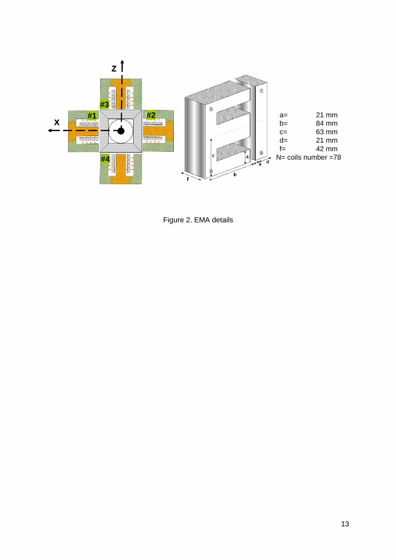
Since an EMA can only produce attractive forces, Four “identical” EMA supplied by
constant currents are utilized. Each EMA is composed of a ferromagnetic circuit and an
electrical circuit. The ferromagnetic circuit has two parts: an (E) shape, which receives the
induction coil, and an (I) shape, which is fixed to the squirrel cage. Both parts are made of
sets of insulated ferromagnetic sheets. The quality of the ferromagnetic circuit alloy is
considered high enough and the nominal air gap between the stator and the beam is small
enough to consider magnetic loss as negligible. The geometries of the actuators are
summarized in Fig. 2.
Assuming negligible eddy current effects and conservative flux, the relationship
between the electromagnetic force (Fem), air gap (e), gap distance (δa) and current (I) for an
action axe can be expressed as:
( ) ( )
2 2 2 20 0
2 22 2
2 2
= − + + − + + −+ + − +
em
a ar r
N a f I N a f IF
b c d a b c d ae e
µ µ
δ δµ µ
(1)
where (a, b, c, d and f ) correspond to the geometrical characteristics of the actuator and µ0
is the magnetic permeability of a vacuum (4π×10-7 H/m). µr is the relative magnetic
permeability (dimensionless) that is a function of the air gap and can be varied according to

5
temperature. Its value is based on manufacturer’s specifications and is generally not known
with great accuracy and has to be identified.
The presence of these electromagnetic forces introduce a softening effects on the
dynamics of the system and produce a shift of the first resonance frequency towards lower
values. Mahfoud et al. (2011) show that this shift depends on the constant current value
applied for a given air gap value.
A model of the actuator is necessary in order to adjust and to control the actual air
gaps. In this model, the inputs are the current and the gap distance; the output is the force.
The geometrical parameters could be measured precisely; the only unknown is the relative
permeability that has to be determined experimentally. The relative permeability is
determined as:
( )
2 20
2 2;
1
+ + −= =
−em
r
b c d a F
e N a f I
βµ β
β µ (2)
A specific experimental arrangement was realized (Fig. 3) in order to measure the
force generated by one actuator, for several air gaps and for increasing and decreasing
values of the input current. We supposed that the three other actuators have the same
characteristics.
The generated forces due to increasing and decreasing input currents are measured
for several air gaps (Fig. 4).
The results obtained show that the hysteresis effect (due to electromagnetic flux)
appears to be negligible and the generated forces are proportional to the current square
value. In the model presented here, the relative permeability is assumed to be constant for
low flux density. The mean value determined for the model is 950.
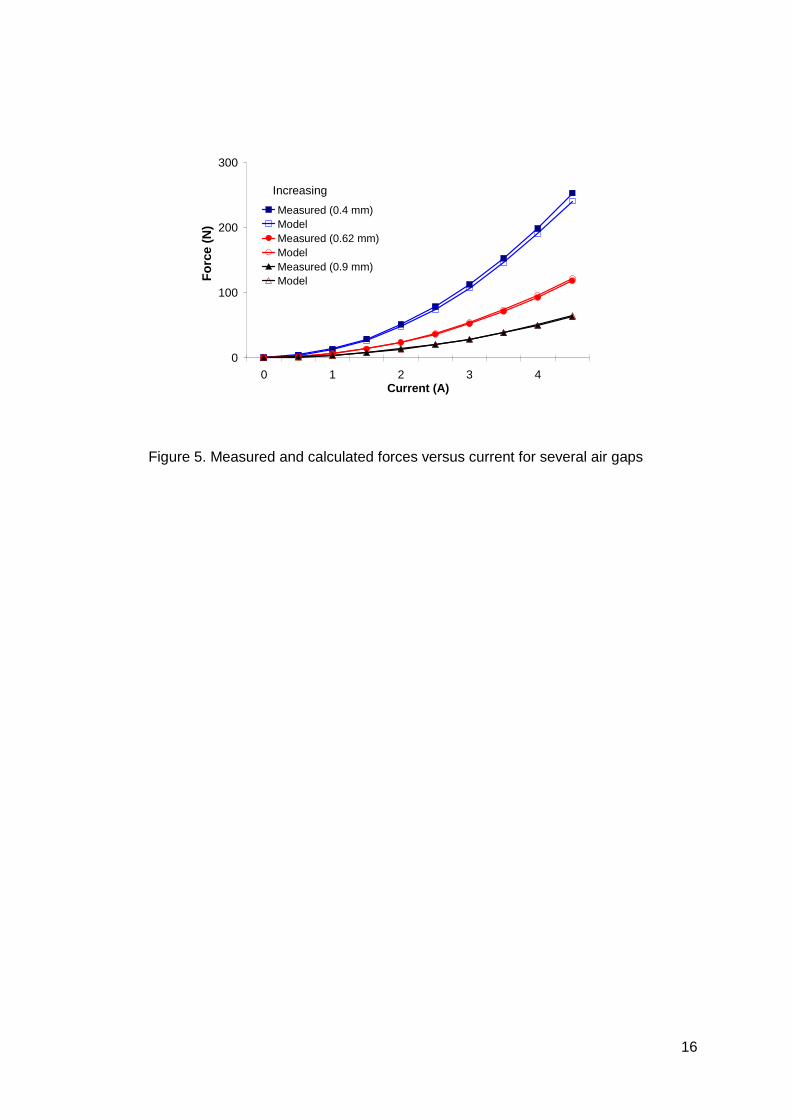
The measured forces due to an increasing current sweep are compared with those
generated by the model for different air gaps in Fig. 5. Same trends were observed for a
decreasing sweep. The model identified, describes closely the behavior of the EMAs

6
especially for large air gaps. From the results obtained, the operating conditions are chosen
as 0.6 mm for the air gap (theoretical value) and 4 A for the current.
4. Experimental investigations
Experiments are carried out in order to assess the dynamic behavior with and without
constant current. Actuators are mounted with the same air gap of 0.6 mm. The
measurements show that the air gaps realized are: 0.621 mm for actuator #1, 0.666 mm for
#2, 0.641 mm for #3 and 0.715 mm for actuator #4. Two configurations are considered in this
paper: without current (0 A) and with constant current (4 A). Even if the air gaps were
different, the actuators have been supplied with the same current. The dynamic behavior of
the test rig is assessed first at rest, and then during run-up or run-down.
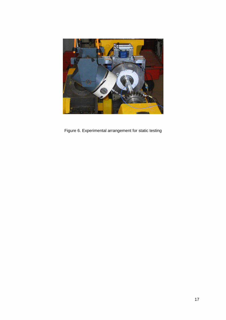
4.1. Behavior at rest
This step is important in order to quantify the shift value of the first critical speed, and
to verify the stability of the behavior with the chosen operating conditions. A GWV20B of 110
N electro-dynamic shaker provided by SS100 power amplifier of Gearing & Watson LTD is
utilized (Fig.6).
An increasing and decreasing, sinusoidal sweep from 22 to 55 Hz is performed for the
two configurations (with and without current). The sweep rate is chosen such that the
measurements correspond to the steady state permanent conditions. The frequency range
chosen includes the first resonance of the test rig. It is worth mentioning that for the
configuration without current, no difference is observed between the two sweeps. Thus, this
configuration is presented by only one curve. The excitation is introduced on disc D2 for both
directions, horizontal and vertical. The applied forces are measured by using a piezoelectric
force sensor (B&K 8200).
The transfer functions measured in the vertical direction at measurement plane #2 are
presented in Fig. 7. The dissymmetric behavior could be noticed easily on the system "linear"
response (without current). Two frequencies, 44.4 and 45.6 Hz are observed; they
7
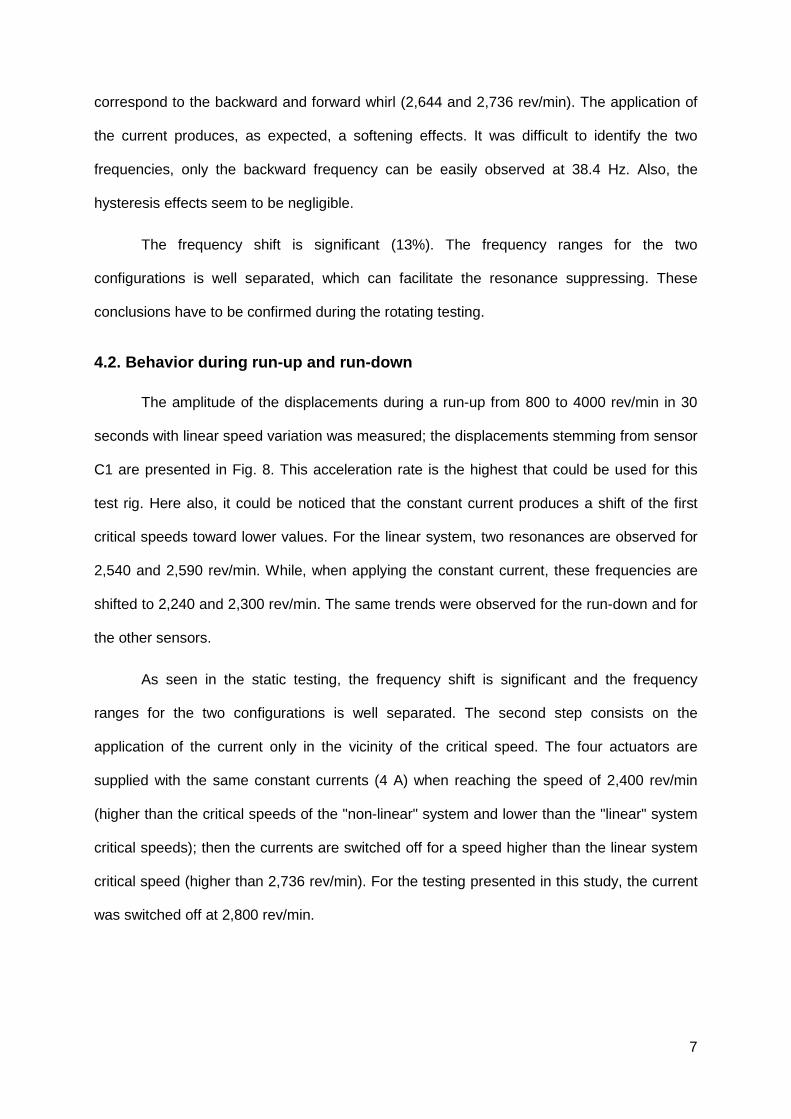
correspond to the backward and forward whirl (2,644 and 2,736 rev/min). The application of
the current produces, as expected, a softening effects. It was difficult to identify the two
frequencies, only the backward frequency can be easily observed at 38.4 Hz. Also, the
hysteresis effects seem to be negligible.
The frequency shift is significant (13%). The frequency ranges for the two
configurations is well separated, which can facilitate the resonance suppressing. These
conclusions have to be confirmed during the rotating testing.
4.2. Behavior during run-up and run-down
The amplitude of the displacements during a run-up from 800 to 4000 rev/min in 30
seconds with linear speed variation was measured; the displacements stemming from sensor
C1 are presented in Fig. 8. This acceleration rate is the highest that could be used for this
test rig. Here also, it could be noticed that the constant current produces a shift of the first
critical speeds toward lower values. For the linear system, two resonances are observed for
2,540 and 2,590 rev/min. While, when applying the constant current, these frequencies are
shifted to 2,240 and 2,300 rev/min. The same trends were observed for the run-down and for
the other sensors.
As seen in the static testing, the frequency shift is significant and the frequency
ranges for the two configurations is well separated. The second step consists on the
application of the current only in the vicinity of the critical speed. The four actuators are
supplied with the same constant currents (4 A) when reaching the speed of 2,400 rev/min
(higher than the critical speeds of the "non-linear" system and lower than the "linear" system
critical speeds); then the currents are switched off for a speed higher than the linear system
critical speed (higher than 2,736 rev/min). For the testing presented in this study, the current
was switched off at 2,800 rev/min.

8
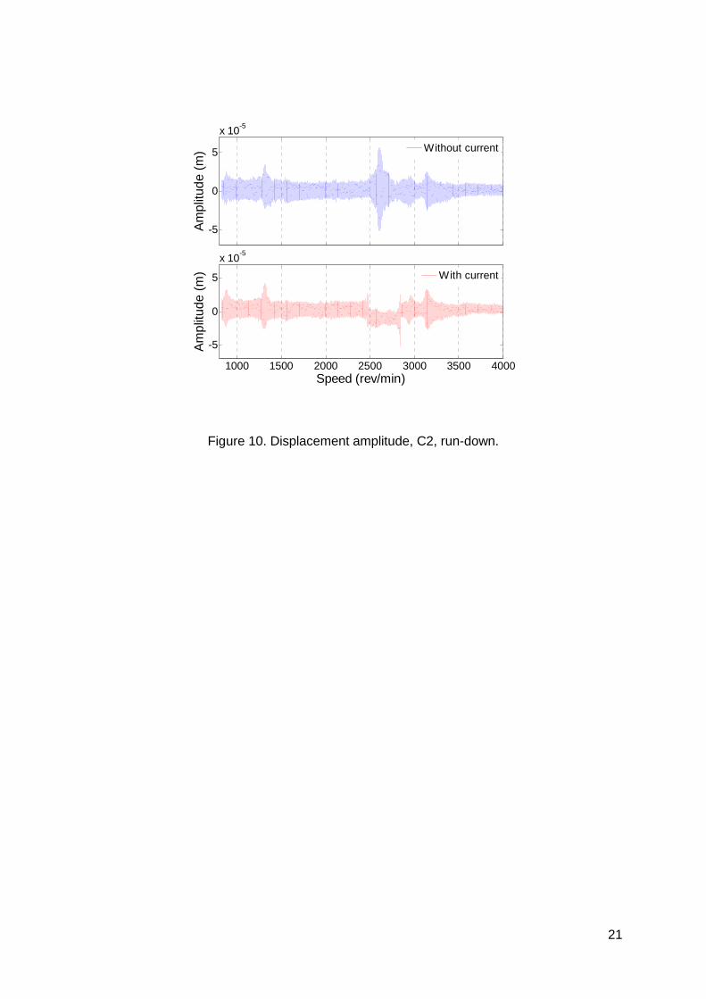
The displacements stemming from sensor C2 during the run-up from 800 to 4000
rev/min in 90 seconds with linear speed variation are presented in Fig. 9. This acceleration
rate is the usual rate utilized for the test rig.
It could be noticed that the rotor does not cross the critical speed during the run-up.
The same behavior was also noticed during the run-down (Fig. 10).
The electromagnetic actuators, utilized in this configuration, provide a "smooth" run-
up or run-down and could enable the suppression of critical speeds. It is worth mentioning
that only the first critical speed was monitored in this study. The position of the hybrid bearing
corresponds to a vibration node for the second mode; consequently the electromagnetic
actuators have no effects on the dynamic behavior.
5. Conclusions
The possibility of suppressing critical speeds by using electromagnetic actuators is
assessed in this study. The approach consists on introducing "when needed" a softening
behavior during operation so that the rotating machine does not cross any critical speeds
during run-up or run-down.
The constant current, when applied to the EMAs, produces a shift of the first critical
speed toward lower values. The phenomena of amplitude jump and the hysteresis effects
produced during run-up or run-down are negligible. The application of a constant current for
a speed interval around the critical speed enables a smooth run-up or run-down without
crossing any resonance.
In this study, only the first critical speed was monitored. The position of the hybrid
bearing corresponds to a vibration node for the second mode; consequently the
electromagnetic actuators have no effects on the dynamic behavior. This approach requires
a good knowledge of the dynamic behavior of the studied system in order to apply the
current for the suitable speed range. It was noticed that the produced dynamic behavior
depends on (and is sensitive to) the current intensity and the air gap value.

9
The amplitude response increases when applying the current (step input), on the
other hand introducing the current with a given rate may introduce instability. Researches are
going on in order to optimize the dynamic behavior as a function of the current intensity and
the air gap values.
This study is an additional interesting utilization of EMA and is not an alternative for
the active control, which is necessary to attenuate the effects of the external excitations.
References
Aenis, M., Knopf, E. and Nordmann, R. (2002), "Active magnetic bearings for the
identification and fault diagnosis in turbomachinery", Mechatronics, 12, 1011-1021.
Der Hagopian, J., Belhaq, M., Seibold, Z. et Mahfoud, J. (2010), "Maîtrise de Phénomènes
de Saut dans les Réponses Fréquentielles des Structures avec Non Linéarité Localisée",
Machines et Industries, 11 (5), 419-425.
El-Shafei, A. and Dimitri, A.S. (2010), "Controlling journal bearing instability using active
magnetic bearings", Journal of Engineering for Gas Turbines and Power, 132, 1-9.
Kasarda, M., Marshall, J. and Prins, R. (2007), "Active magnetic bearing based force
measurement using the multi-point technique", Mechanics Research Communications, 34,
pp. 44-53.
Kasarda, M., Mendoza, H., Kirk, R.G. and Wicks, A. (2004), "Reduction of subsynchronous
vibrations in a single-disk rotor using an active magnetic damper", Mechanics Research
Communications, 31, 689-695.
Kulesza, Z., Sawicki, J.T. and Storozhev, D.L. (2010), "Smart Properties of AMB Supported
Machines for Rotor Crack Detection: Experimental and Analytical Study", Proceedings of the
8th IFToMM International Conference on Rotordynamics, September 12-15, KIST, Seoul,
Korea.

10
Larsonneur, R. and Richard, P. (2008), "Smart Turbomachines using Active Magnetic
Bearings", Paper GT2008-51299, ASME Turbo Expo, Berlin, Germany, June 9-13.
Lei, S. and Palazzolo, A. (2008), "Control of flexible rotor systems with active magnetic
bearings", Journal of Sound and Vibration, 314 (1-2), 19-38.
Mahfoud, J. and Der Hagopian, J. (2011), "Fuzzy Active Control Of Flexible Structures By
Using Electromagnetic Actuators", ASCE's Journal of Aerospace Engineering, 24 (3), 329-
337.
Mani, G., Quinn, D.D. and Kasaeda, M. (2006), "Active health monitoring in a rotating
cracked shaft using active magnetic bearings as force actuators", Journal of Sound and
Vibration, 294, 454-465.
Maslen, E. H. (2008), "Smart Machine Advances in Rotating Machinery". IMechE, Exeter,
UK, 8-10 September.
Schweitzer, G., Bleuler, H. and Traxler, A. (2003), Active Magnetic Bearings - Basics,
Properties and Applications, vdf Hochschulverlag AG, ETH, Zurich.
Souza Morais, T., Steffen Jr, V., Mahfoud, J. and Der Hagopian, J. (2010), "Unbalance
Identification in Nonlinear Rotors", Proceedings of the 8th IFToMM International Conference
on Rotordynamics, September 12-15, KIST, Seoul, Korea.
Souza Morais, T., Steffen Jr, V., Mahfoud, J. and Der Hagopian, J. (2009), "Monitoring
Cracked Shaft By Using Active Electro-Magnetic Actuator - Numerical Simulation", 20th
International Congress of Mechanical Engineering, COBEM 2009, November 15-20,
Gramado, RS, Brazil.
11
Figure caption
Figure 1 Experimental test rig
Figure 2 EMA details
Figure 3 Experimental arrangement for the actuator identification
Figure 4 Measured forces and relative permeability versus current for several air gaps
Figure 5 Measured and calculated forces versus current for several air gaps
Figure 6 Experimental arrangement for static testing
Figure 7 Transfer function, C3, sinusoidal sweep, with and without current
Figure 8 Displacement amplitude, C2, 800 to 4000 rev/min in 30 sec
Figure 9 Displacement amplitude, C2, run-up
Figure 10 Displacement amplitude, C2, run-down

12
FIGURES
Tacho
Measurement Planes#1
#2
B2
D1
D2
B1 B2
Y
X
Z
0.120.1940.3290.269
0.959
D1D2
Tacho
Measurement Planes#1
#2
B2
D1
D2
B1 B2
Y
X
Z
0.120.1940.3290.269
0.959
D1D2
Figure 1. Experimental test rig
13
#1 #2
#4
#3
X
Z
#1 #2
#4
#3
X
Z
a= 21 mmb= 84 mmc= 63 mmd= 21 mmf= 42 mm
N= coils number =78
Figure 2. EMA details

14
Figure 3. Experimental arrangement for the actuator identification

15
0
100
200
300
0 1 2 3 4 5Current (A)
Fo
rce
(N)
0.4 mm Increasing
Decreasing
0.62 mm Increasing
Decreasing
0.9 mm Increasing
Decreasing
500
2000
3500
5000
0 1 2 3 4 5Current (A)
µµ µµ_r
Figure 4. Measured forces and relative permeability versus current for several air gaps
16
Increasing
0
100
200
300
0 1 2 3 4Current (A)
Fo
rce
(N)
Measured (0.4 mm)ModelMeasured (0.62 mm)ModelMeasured (0.9 mm)Model
Figure 5. Measured and calculated forces versus current for several air gaps
17
Figure 6. Experimental arrangement for static testing

18
25 30 35 40 45 50 5510
-9
10-8
10-7
10-6
10-5
Frequency (Hz)
Am
plitu
de (
Z/F
)
IncreasingDecreasingWithout current
Figure 7. Transfer function, C3, sinusoidal sweep, with and without current

19
-5
0
5
x 10-5
Am
plitu
de (
m)
1000 1500 2000 2500 3000
-5
0
5
x 10-5
Speed (rev/min)
Am
plitu
de (
m)
With current
Without current
Figure 8. Displacement amplitude, C2, 800 to 4000 rev/min in 30 sec

20
-5
0
5
x 10-5
Am
plitu
de (
m)
1000 1500 2000 2500 3000 3500 4000
-5
0
5
x 10-5
Speed (rev/min)
Am
plitu
de (
m)
Without current
With current
Figure 9. Displacement amplitude, C2, run-up.
21
-5
0
5
x 10-5
Am
plitu
de (
m)
1000 1500 2000 2500 3000 3500 4000
-5
0
5
x 10-5
Speed (rev/min)
Am
plitu
de (
m)
With current
Without current
Figure 10. Displacement amplitude, C2, run-down.