Embed Size (px)
Citation preview
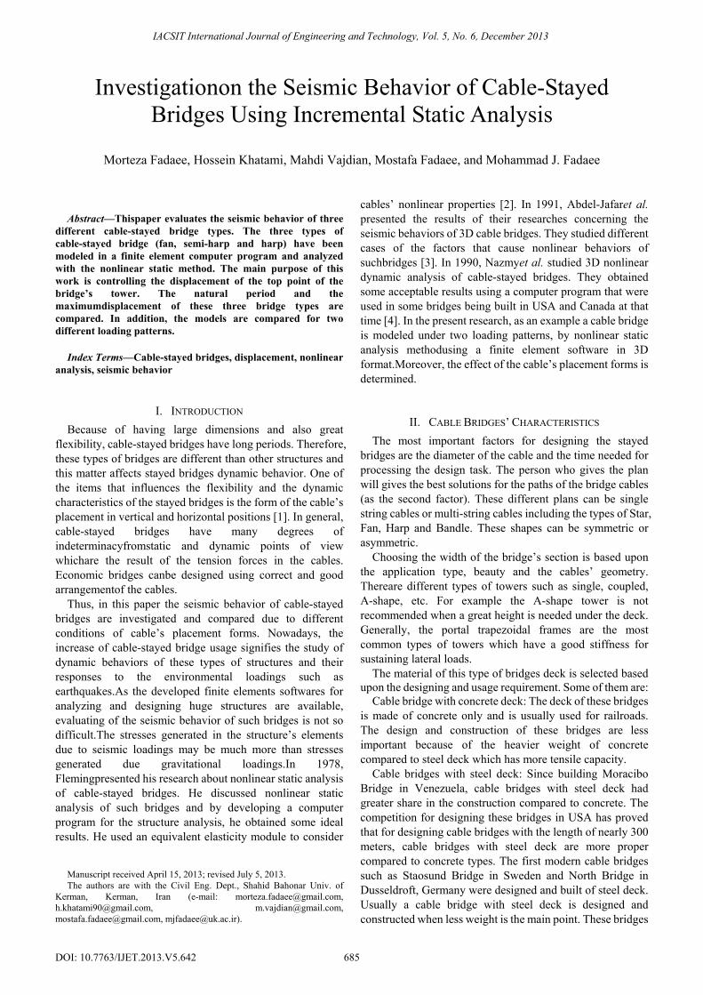
Abstract—Thispaper evaluates the seismic behavior of three
different cable-stayed bridge types. The three types of cable-stayed bridge (fan, semi-harp and harp) have been modeled in a finite element computer program and analyzed with the nonlinear static method. The main purpose of this work is controlling the displacement of the top point of the bridge’s tower. The natural period and the maximumdisplacement of these three bridge types are compared. In addition, the models are compared for two different loading patterns.
Index Terms—Cable-stayed bridges, displacement, nonlinear analysis, seismic behavior
I. INTRODUCTION Because of having large dimensions and also great
flexibility, cable-stayed bridges have long periods. Therefore, these types of bridges are different than other structures and this matter affects stayed bridges dynamic behavior. One of the items that influences the flexibility and the dynamic characteristics of the stayed bridges is the form of the cable’s placement in vertical and horizontal positions [1]. In general, cable-stayed bridges have many degrees of indeterminacyfromstatic and dynamic points of view whichare the result of the tension forces in the cables. Economic bridges canbe designed using correct and good arrangementof the cables.
Thus, in this paper the seismic behavior of cable-stayed bridges are investigated and compared due to different conditions of cable’s placement forms. Nowadays, the increase of cable-stayed bridge usage signifies the study of dynamic behaviors of these types of structures and their responses to the environmental loadings such as earthquakes.As the developed finite elements softwares for analyzing and designing huge structures are available, evaluating of the seismic behavior of such bridges is not so difficult.The stresses generated in the structure’s elements due to seismic loadings may be much more than stresses generated due gravitational loadings.In 1978, Flemingpresented his research about nonlinear static analysis of cable-stayed bridges. He discussed nonlinear static analysis of such bridges and by developing a computer program for the structure analysis, he obtained some ideal results. He used an equivalent elasticity module to consider
The authors are with the Civil Eng. Dept., Shahid Bahonar Univ. of Kerman, Kerman, Iran (e-mail: [email protected], [email protected], [email protected], [email protected], [email protected]).
cables’ nonlinear properties [2]. In 1991, Abdel-Jafaret al. presented the results of their researches concerning the seismic behaviors of 3D cable bridges. They studied different cases of the factors that cause nonlinear behaviors of suchbridges [3]. In 1990, Nazmyet al. studied 3D nonlinear dynamic analysis of cable-stayed bridges. They obtained some acceptable results using a computer program that were used in some bridges being built in USA and Canada at that time [4]. In the present research, as an example a cable bridge is modeled under two loading patterns, by nonlinear static analysis methodusing a finite element software in 3D format.Moreover, the effect of the cable’s placement forms is determined.
II. CABLE BRIDGES’ CHARACTERISTICS The most important factors for designing the stayed
bridges are the diameter of the cable and the time needed for processing the design task. The person who gives the plan will gives the best solutions for the paths of the bridge cables (as the second factor). These different plans can be single string cables or multi-string cables including the types of Star, Fan, Harp and Bandle. These shapes can be symmetric or asymmetric.
Choosing the width of the bridge’s section is based upon the application type, beauty and the cables’ geometry. Thereare different types of towers such as single, coupled, A-shape, etc. For example the A-shape tower is not recommended when a great height is needed under the deck. Generally, the portal trapezoidal frames are the most common types of towers which have a good stiffness for sustaining lateral loads.
The material of this type of bridges deck is selected based upon the designing and usage requirement. Some of them are:
Cable bridge with concrete deck: The deck of these bridges is made of concrete only and is usually used for railroads. The design and construction of these bridges are less important because of the heavier weight of concrete compared to steel deck which has more tensile capacity.
Cable bridges with steel deck: Since building Moracibo Bridge in Venezuela, cable bridges with steel deck had greater share in the construction compared to concrete. The competition for designing these bridges in USA has proved that for designing cable bridges with the length of nearly 300 meters, cable bridges with steel deck are more proper compared to concrete types. The first modern cable bridges such as Staosund Bridge in Sweden and North Bridge in Dusseldroft, Germany were designed and built of steel deck. Usually a cable bridge with steel deck is designed and constructed when less weight is the main point. These bridges
Investigationon the Seismic Behavior of Cable-Stayed Bridges Using Incremental Static Analysis
Morteza Fadaee, Hossein Khatami, Mahdi Vajdian, Mostafa Fadaee, and Mohammad J. Fadaee
IACSIT International Journal of Engineering and Technology, Vol. 5, No. 6, December 2013
685DOI: 10.7763/IJET.2013.V5.642
Manuscript received April 15, 2013; revised July 5, 2013.
are designed for places that have a low resistant soil and a long span is considered.
Cable bridges with combination of steel and concrete deck: These types of bridges are more economic than other used types. The Sunshine Bridge in Tampa gulf in Florida, USA, is for a 6-lane highway. The main span of the bridge is 336 meters long and the length of the pathways is 147 meters. Its height from the water surface is 55 meters and the towers have a height of 84 meters from the above of the deck. The combined deck is made of steel grids and prefabricated concrete parts. This bridge has the ability to resist great tornados.
Other Sections are the prefabricated types and trusses that are used as carrier beams.
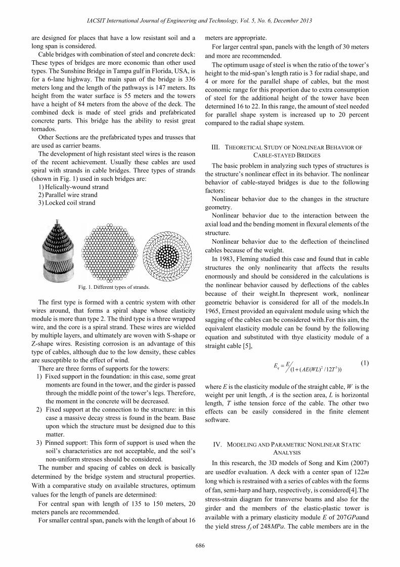
The development of high resistant steel wires is the reason of the recent achievement. Usually these cables are used spiral with strands in cable bridges. Three types of strands (shown in Fig. 1) used in such bridges are:
1) Helically-wound strand 2) Parallel wire strand 3) Locked coil strand
Fig. 1. Different types of strands.
The first type is formed with a centric system with other
wires around, that forms a spiral shape whose elasticity module is more than type 2. The third type is a three wrapped wire, and the core is a spiral strand. These wires are wielded by multiple layers, and ultimately are woven with S-shape or Z-shape wires. Resisting corrosion is an advantage of this type of cables, although due to the low density, these cables are susceptible to the effect of wind.
There are three forms of supports for the towers: 1) Fixed support in the foundation: in this case, some great
moments are found in the tower, and the girder is passed through the middle point of the tower’s legs. Therefore, the moment in the concrete will be decreased.
2) Fixed support at the connection to the structure: in this case a massive decay stress is found in the beam. Base upon which the structure must be designed due to this matter.
3) Pinned support: This form of support is used when the soil’s characteristics are not acceptable, and the soil’s non-uniform stresses should be considered.
The number and spacing of cables on deck is basically determined by the bridge system and structural properties. With a comparative study on available structures, optimum values for the length of panels are determined:
For central span with length of 135 to 150 meters, 20 meters panels are recommended.
For smaller central span, panels with the length of about 16
meters are appropriate. For larger central span, panels with the length of 30 meters
and more are recommended. The optimum usage of steel is when the ratio of the tower’s
height to the mid-span’s length ratio is 3 for radial shape, and 4 or more for the parallel shape of cables, but the most economic range for this proportion due to extra consumption of steel for the additional height of the tower have been determined 16 to 22. In this range, the amount of steel needed for parallel shape system is increased up to 20 percent compared to the radial shape system.
III. THEORETICAL STUDY OF NONLINEAR BEHAVIOR OF CABLE-STAYED BRIDGES
The basic problem in analyzing such types of structures is the structure’s nonlinear effect in its behavior. The nonlinear behavior of cable-stayed bridges is due to the following factors:
Nonlinear behavior due to the changes in the structure geometry.
Nonlinear behavior due to the interaction between the axial load and the bending moment in flexural elements of the structure.
Nonlinear behavior due to the deflection of theinclined cables because of the weight.
In 1983, Fleming studied this case and found that in cable structures the only nonlinearity that affects the results enormously and should be considered in the calculations is the nonlinear behavior caused by deflections of the cables because of their weight.In thepresent work, nonlinear geometric behavior is considered for all of the models.In 1965, Ernest provided an equivalent module using which the sagging of the cables can be considered with.For this aim, the equivalent elasticity module can be found by the following equation and substituted with thye elasticity module of a straight cable [5],
))12/)((1( 32 TWLAEEEq += (1)
where E is the elasticity module of the straight cable, W is the weight per unit length, A is the section area, L is horizontal length, T isthe tension force of the cable. The other two effects can be easily considered in the finite element software.
IV. MODELING AND PARAMETRIC NONLINEAR STATIC ANALYSIS
In this research, the 3D models of Song and Kim (2007) are usedfor evaluation. A deck with a center span of 122m long which is restrained with a series of cables with the forms of fan, semi-harp and harp, respectively, is considered[4].The stress-strain diagram for transverse beams and also for the girder and the members of the elastic-plastic tower is available with a primary elasticity module E of 207GPaand the yield stress fy of 248MPa. The cable members are in the
IACSIT International Journal of Engineering and Technology, Vol. 5, No. 6, December 2013
686
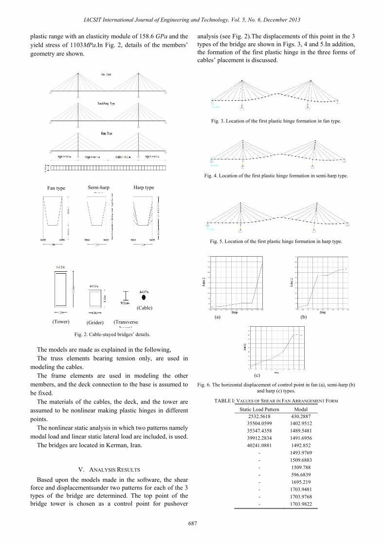
plastic range with an elasticity module of 158.6 GPa and the yield stress of 1103MPa.In Fig. 2, details of the members’ geometry are shown.
Fig. 2. Cable-stayed bridges’ details.
The models are made as explained in the following, The truss elements bearing tension only, are used in
modeling the cables. The frame elements are used in modeling the other
members, and the deck connection to the base is assumed to be fixed.
The materials of the cables, the deck, and the tower are assumed to be nonlinear making plastic hinges in different points.
The nonlinear static analysis in which two patterns namely modal load and linear static lateral load are included, is used.
The bridges are located in Kerman, Iran.
V. ANALYSIS RESULTS Based upon the models made in the software, the shear
force and displacementsunder two patterns for each of the 3 types of the bridge are determined. The top point of the bridge tower is chosen as a control point for pushover
analysis (see Fig. 2).The displacements of this point in the 3 types of the bridge are shown in Figs. 3, 4 and 5.In addition, the formation of the first plastic hinge in the three forms of cables’ placement is discussed.
Fig. 3. Location of the first plastic hinge formation in fan type.
Fig. 4. Location of the first plastic hinge formation in semi-harp type.
Fig. 5. Location of the first plastic hinge formation in harp type.
Fig. 6. The horizontal displacement of control point in fan (a), semi-harp (b)
and harp (c) types.
TABLE I: VALUES OF SHEAR IN FAN ARRANGEMENT FORM
Static Load Pattern Modal 2532.5618 430.2887 35504.0599 1402.9512 35347.4358 1489.5481 39912.2834 1491.6956 40241.0881 1492.852
- 1493.9769 - 1509.6883 - 1509.788 - 596.6839 - 1695.219 - 1703.9481 - 1703.9768 - 1703.9822
(a) (b)
(c)
Fan type Semi-harp type
Harp type
(Tower) (Grider) (Transverse beam)
(Cable)
IACSIT International Journal of Engineering and Technology, Vol. 5, No. 6, December 2013
687
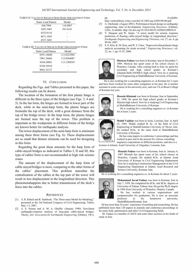
TABLE II: VALUES OF SHEAR IN SEMI-HARP ARRANGEMENT FORM
Static Load Pattern Modal 368.7994 118.0907
1693.3465 391.6141 4332.0116 - 4871.3585 - 4527.2402 -
TABLE III: VALUES OF SHEAR IN HARP ARRANGEMENT FORM
Static Load Pattern Modal 6591.14660 113.0222905 7901.24686 113.0264087 4344.28801 113.1388545 8749.35918 - 9042.32127 -
VI. CONCLUSION Regarding the Figs. and Tables presented in this paper, the
following results can be drawn. The location of the formation of the first plastic hinge is
different in the three types of the bridgen (see Figs. 3, 4 and 5). In the fan form, the hinges are formed in lower part of the deck, while in the semi-harp form, the plastic hinges are formedin the top of the deck, with a great distance from the top of the bridge tower. In the harp form, the plastic hinges are formed near the top of the tower. This problem is important as the weakpoints in different forms of the bridge are known better for earthquake analysis.
The tower displacement of the semi-harp form is minimum among these three forms (see Fig. 6). These displacements are so small that thinner elements can be used for designing in this form.
Regarding the great shear amounts for the harp form of cable-stayed bridges as indicated in Tables I, II and III, this type of cables’form is not recommended in high risk seismic zones.
The amount of the displacement of the harp form of cable-stayed bridges is more, comparing to the other forms of the cables’ placement. This problem statesthat the centralization of the cables at the top part of the tower will result in less displacement in the longitudinal direction. This phenomenahappens due to better transmission of the deck’s force into the cables.
REFERENCES [1] A. R. Rahaii and R. Sarkhosh, “The Three-mass Model for Modeling,”
presented at the 3rd National Congress of Civil Engineering, Tabriz, May 1-3, 2007.
[2] A. S. Nazmy and A. M. A. Ghaffar. (January 1990). Non-linear earthquake-response analysis of long-span cable-stayed bridges: Theory. Intl. Association for Earthquake Engineering. [Online]. 19(1).
pp. Available: http://onlinelibrary.wiley.com/doi/10.1002/eqe.4290190106/pdf
[3] A. Ghobarah. (August 2001). Performance-based design in earthquake engineering: state of development. Engineering Structures. [Online]. 23(8). Available: http://dx.doi.org/10.1016/S0141-0296(01)00036-0
[4] Y. Haiquan and W. Junjie, “A tower model for seismic response prediction of floating cable-stayed bridge in longitudinal direction,” Earthquake Engineering and Engineering Vibration, vol. 27, no. 4, pp 80-86, 2007.
[5] S. E. Kim, K. M. Kim, and W. F. Chen, “Improved refined plastic hinge analysis accounting for strain reversal,” Engineering Structures, vol. 22, no. 1, pp 15-25, 2000.
Morteza Fadaee was born in Kerman, Iran in December 7, 1989. Morteza has spent some of his school classes in Waterloo, Canada. After coming back to Iran, he spent his secondary and high school grades at Kerman’s Allameh-Helli (NODET) high school. Now he is studying Civil Engineering at ShahidBahonar University of Kerman.
He is also working for a consulting engineers co. in Kerman for 2 years and have been worked for some other companies in his past. He is teacher assistant in some courses in his university now, and was TA in Besat College of Kerman last year.
Hossein Khatami was born in Kerman, Iran in September 21, 1990. He spent his high school grades at Kerman’s Shariati high school. Now he is studying Civil Engineering at ShahidBahonar University of Kerman.
He is working for a consulting engineers co. in Kerman for at least 2 years.
Mahdi Vajdian was born in Azna, Lorestan, Iran in April 25, 1985. Mahdi studied B. Sc. of the field of Civil Engineering at ShahidChamran University of Ahvaz, Iran. He studied M.Sc. in the same field at ShahidBahonar University of Kerman.
He has some papers in conference’s proceedings and has worked in past and in the present for various consulting engineers corporations in different positions, and also is a
lecturer in Islamic Azad University of Aligudarz, Lorestan, Iran.
Mostafa Fadaee was born in Kerman, Iran in January 4, 1987 Mostafa has spent some of his school classes in Waterloo, Canada. He studied B.Sc. at Islamic Azad University of Kerman in Civil Engineering Deptartment Now he is studying Construction Management in the Civil Engineering Department at Islamic Azad Research and Science University, Kerman, Iran.
He is working for a consulting engineers co. in Kerman for about 3 years.
Mohammad Javad Fadaee was born in Kerman, Iran in July 7, 1958. He completed his B.Sc. and M.Sc. degrees at University of Tehran, Tehran, Iran. He got his Ph.D. degree in 1996 from University of Waterloo, Ontario, Canada.
He has worked in various organizations and companiesafter his graduation. He is now an associate professor in his hometown university; ShahidBahonarKerman, Iran.
He has more than 26 years’ experience of teaching and researching. He has published more than 120 papers in journals and conference proceedings in his main field, optimization and other Civil Engineering fields.
Dr. Fadaee is a member of ASCE and some other societies in his fields of study in Iran.
IACSIT International Journal of Engineering and Technology, Vol. 5, No. 6, December 2013
688