Embed Size (px)
Citation preview
DRO Deakin Research Online, Deakin University’s Research Repository Deakin University CRICOS Provider Code: 00113B
Investigation on the effect of a pre-center drill hole and tool material on thrust force, surface roughness, and cylindricity in the drilling of Al7075
Citation: Ghasemi, Amir Hossein, Khorasani, Amir Mahyar and Gibson, Ian 2018, Investigation on the effect of a pre-center drill hole and tool material on thrust force, surface roughness, and cylindricity in the drilling of Al7075, Materials, vol. 11, no. 1, Article number: 140, pp. 1-15.
DOI: http://www.dx.doi.org/10.3390/ma11010140
© 2018, The Authors
Reproduced by Deakin University under the terms of the Creative Commons Attribution Licence
Downloaded from DRO: http://hdl.handle.net/10536/DRO/DU:30109270
materials
Article
Investigation on the Effect of a Pre-Center Drill Holeand Tool Material on Thrust Force, SurfaceRoughness, and Cylindricity in the Drilling of Al7075
Amir Hossein Ghasemi 1, Amir Mahyar Khorasani 2,* and Ian Gibson 2 ID
1 Department of Manufacturing and Production, University of Kashan, Qotb-e Ravandi Blvd.,Kashan 8731753153, Iran; [email protected]
2 School of Engineering, Faculty of Science, Engineering and Built Environment, Deakin University,Victoria 3216, Australia; [email protected]
* Correspondence: [email protected]
Received: 8 December 2017; Accepted: 6 January 2018; Published: 16 January 2018
Abstract: Drilling is one of the most useful metal cutting processes and is used in various applications,such as aerospace, electronics, and automotive. In traditional drilling methods, the thrust force,torque, tolerance, and tribology (surface roughness) are related to the cutting condition and toolgeometry. In this paper, the effects of a pre-center drill hole, tool material, and drilling strategy(including continuous and non-continuous feed) on thrust force, surface roughness, and dimensionalaccuracy (cylindricity) have been investigated. The results show that using pre-center drill holesleads to a reduction of the engagement force and an improvement in the surface quality andcylindricity. Non-continuous drilling reduces the average thrust force and cylindricity value, andHigh Speed Steels HSS-Mo (high steel speed + 5–8% Mo) reduces the maximum quantity of cuttingforces. Moreover, cylindricity is directly related to cutting temperature and is improved by using anon-continuous drilling strategy.
Keywords: drilling; thrust force; pre-center drill hole; surface roughness
1. Introduction
Drilling is one of the popular machining methods and is used in most assembly processes. Variousaspects of drilling have been investigated, such as process modelling, tool material, cutting force, andsurface roughness [1–5].
Klocke and Krieg studied various properties of coated drills. They found tool coating life isassociated with workpiece materials due to the formation of a built-up edge on cutting edges, andthis problem can be solved by using appropriate cutting fluids. The affinity of coated layers andworkpiece materials is found to be the main reason for a reduction in tool life [6]. Kelly and Cotterellcompared the effects of traditional and minimum quantity lubricant (MQL) to analyse the effect oflubrication on surface roughness, thrust force, and machining torque. The results proved that the MQLnozzle, workpiece material, and MQL particle size are significant to the generation of thrust forceand surface roughness [7]. Tsao and Hocheng investigated the effects of cutting-edge length and tooldiameter on composite delamination during the drilling of fibre-reinforced composites. The outcomesof this research illustrated that increasing the cutting-edge length and feed rate is a direct function ofdelamination. Furthermore, the value of thrust force is related to the hole depth. They also presentedanalytical models with acceptable accuracy compared to the experimental results [8]. Paro et al., studiedthe drilling of X2 Cr Ni 19 11 stainless steel by using TiN- and TiCN-coated tools. They investigatedthe effect of feed rate and cutting speed on thrust force and tool life, and found that feed rate is themost influential factor on chip formation [9]. Bakkal et al. studied bulk metallic glass (BMG) drilling
Materials 2018, 11, 140; doi:10.3390/ma11010140 www.mdpi.com/journal/materials
Materials 2018, 11, 140 2 of 15
and analysed the effect of the cutting condition on thrust force, torque, and tool wear. They foundthat WC-Co (Tungsten carbide + Cobalte) is an acceptable tool for drilling BMG, and by increasing thecutting speed and decreasing the feed rate the mentioned results were improved. However, drillingat a higher speed causes faster and more tool wear [10]. Astakhov and Galitsky studied tool life onmalleable cast iron by using single-edge drill bits. The effect of different tool angles and feed rateswas studied and optimized [11]. Bagci and Ozcelik studied the effect of depth, feed rate, and cuttingspeed on drilling temperature and thrust force in Al7075 by using TiN/TiAlN-coated carbide drills.The result showed that drilling depth is an effective parameter on machining temperature followed bycutting speed and feed rate [12]. Ke et al. investigated chip formation during deep hole drilling andproposed an analytical model to predict the machining force during the drilling process [13]. Using acore drill leads to increased feed without increasing delamination in the drilling of composites, and theefficiency of the process improves by optimization in tool design. Also, in the machining of composites,using coated HSS drills leads to an enhancement of surface quality [14–16]. Olovsjo et al. studiedgrain size and hardness effects in the drilling of Inconel 718 by a cemented carbide tool and observedthat the hardness and grain size affect the deformation layer of workpieces [17]. Using design ofexperiment methods, such as Taguchi and response surface, showed that feed rate and cutting speedare the most influential parameters on the drilling of steels. Different machining methods, such asultrasonic drilling, and tool selection leads to better surface quality and drilling of soft materials, suchas Al, and helical milling increases fatigue life [18–20]. The effect of pre-hole drilling on Al 6061-7075with uncoated HSS drills showed that pre-holes reduce cutting force and improve surface roughnessand chip generation [21].
P. Nieslony et al. studied the effects of tool coating in the drilling of explosively clad Ti–steelplates and found that tool material affects drilling force, torque, and surface morphology [22]. Theyalso compared the surface morphology produced by WC-Co- and TiAlN-coated tools in differentmachining zones and found that drilling with carbide tools can achieve better surface quality [23].M. Percin et al. [24] studied the effect of machining parameters and machining conditions on the force,torque, surface roughness, and tool wear in the micro-drilling of Ti-6Al-4V and found that both themachining parameters and cutting condition have an effect on drilling force and torque and that thebuilt-up edge (BUE) is highly related to the tool wear mechanism. F. Berzosa et al. [25] studied toolselection and cutting condition in the drilling of Magnesium UNSM11917. They found that minimumquantity lubricant has a significant effect on reducing surface roughness and that cutting speed isthe most effective parameter that affects surface roughness. B. Vakili Azghandi et al. [26] studiedthe relation between ultrasonic vibration-assisted drilling and cutting force, and found that usingultrasonic vibration causes a decrease in the average force of drilling. Suman Chatterjee et al. studiedthe simulation and optimization of cutting force and torque in the drilling of Ti-6Al-4V alloy usingDeformed 3D software, and they report optimal values of cutting speed and feed rate to achieve thelowest drilling force [27].
However, there appears to be a lack of research into the use of different cutters, drilling strategies,and pre-center hole drilling on cutting force, surface quality, and cylindricity.
Tool selection and tolerances are the most important factors in the machining of Al7075.An accurate tool selection and low dimensional deviations improves industrial parts in terms ofproduction cost, time, and quality. This paper investigates the effects of tool material, a pre-center drillhole, and drilling strategy on the thrust force in and surface roughness of drilled holes. A full factorialdesign of experiment (DOE) has been selected to achieve higher accuracy.
2. Material and Methods
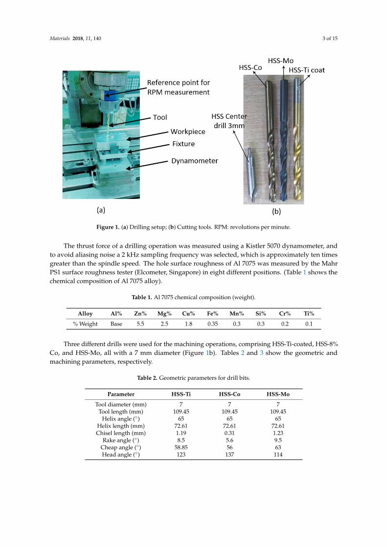
Our experimental procedure includes drilling followed by the measurement of force, surfaceroughness, and cylindricity. A computer numerical control (CNC) milling machine with a hydraulictransfer system was used as shown in Figure 1a.
Materials 2018, 11, 140 3 of 15
Materials 2018, 11, 140 3 of 14
surface roughness tester (Elcometer, Singapore) in eight different positions. (Table 1 shows the chemical composition of Al 7075 alloy).
Table 1. Al 7075 chemical composition (weight).
Alloy Al% Zn% Mg% Cu% Fe% Mn% Si% Cr% Ti% % Weight Base 5.5 2.5 1.8 0.35 0.3 0.3 0.2 0.1
Three different drills were used for the machining operations, comprising HSS-Ti-coated, HSS-8% Co, and HSS-Mo, all with a 7 mm diameter (Figure 1b). Tables 2 and 3 show the geometric and machining parameters, respectively.
Figure 1. (a) Drilling setup; (b) Cutting tools. RPM: revolutions per minute.
Table 2. Geometric parameters for drill bits.
Parameter HSS-Ti HSS-Co HSS-MoTool diameter (mm) 7 7 7
Tool length (mm) 109.45 109.45 109.45 Helix angle (°) 65 65 65
Helix length (mm) 72.61 72.61 72.61 Chisel length (mm) 1.19 0.31 1.23
Rake angle (°) 8.5 5.6 9.5 Cheap angle (°) 58.85 56 63 Head angle (°) 123 137 114
To obtain higher accuracy, a full factorial DOE for two factors in three levels has been used [28,29].
Table 3. Machining parameters.
Parameter ValueCutting speed 25 m/min (1137 RPM)
Feed rate 50 mm/min (0.44 mm/rev) Tool overhang length 73.52 mm
Figure 1. (a) Drilling setup; (b) Cutting tools. RPM: revolutions per minute.
The thrust force of a drilling operation was measured using a Kistler 5070 dynamometer, andto avoid aliasing noise a 2 kHz sampling frequency was selected, which is approximately ten timesgreater than the spindle speed. The hole surface roughness of Al 7075 was measured by the MahrPS1 surface roughness tester (Elcometer, Singapore) in eight different positions. (Table 1 shows thechemical composition of Al 7075 alloy).
Table 1. Al 7075 chemical composition (weight).
Alloy Al% Zn% Mg% Cu% Fe% Mn% Si% Cr% Ti%
% Weight Base 5.5 2.5 1.8 0.35 0.3 0.3 0.2 0.1
Three different drills were used for the machining operations, comprising HSS-Ti-coated, HSS-8%Co, and HSS-Mo, all with a 7 mm diameter (Figure 1b). Tables 2 and 3 show the geometric andmachining parameters, respectively.
Table 2. Geometric parameters for drill bits.
Parameter HSS-Ti HSS-Co HSS-Mo
Tool diameter (mm) 7 7 7Tool length (mm) 109.45 109.45 109.45
Helix angle (◦) 65 65 65Helix length (mm) 72.61 72.61 72.61Chisel length (mm) 1.19 0.31 1.23
Rake angle (◦) 8.5 5.6 9.5Cheap angle (◦) 58.85 56 63Head angle (◦) 123 137 114
Materials 2018, 11, 140 4 of 15
Table 3. Machining parameters.
Parameter Value
Cutting speed 25 m/min (1137 RPM)Feed rate 50 mm/min (0.44 mm/rev)
Tool overhang length 73.52 mm
To obtain higher accuracy, a full factorial DOE for two factors in three levels has been used [28,29].Three different drilling strategies—continuous, non-continuous with 1 mm reciprocation
movement (G82), and non-continuous with full reciprocating movement (G83)—were used in thisexperiment. The effect of drilling with and without the pre-center drill holes was also studied inall experiments. Tool overhang was 73.52 ± 0.02 mm and was controlled before each machiningoperation. The orthogonality of the cutting tool and the workpiece was monitored by a dial indicatorafter each tool change and±5 µm was obtained, which was considered acceptable. To have a consistenttemperature throughout the experiments, between each two tests the machine was turned off for30 min. After each test, the cutting edge was monitored by a Visual Measuring Machine (VMM, Yihui,Guangdong, China) to check tool wear and maintain consistency in the experiments.
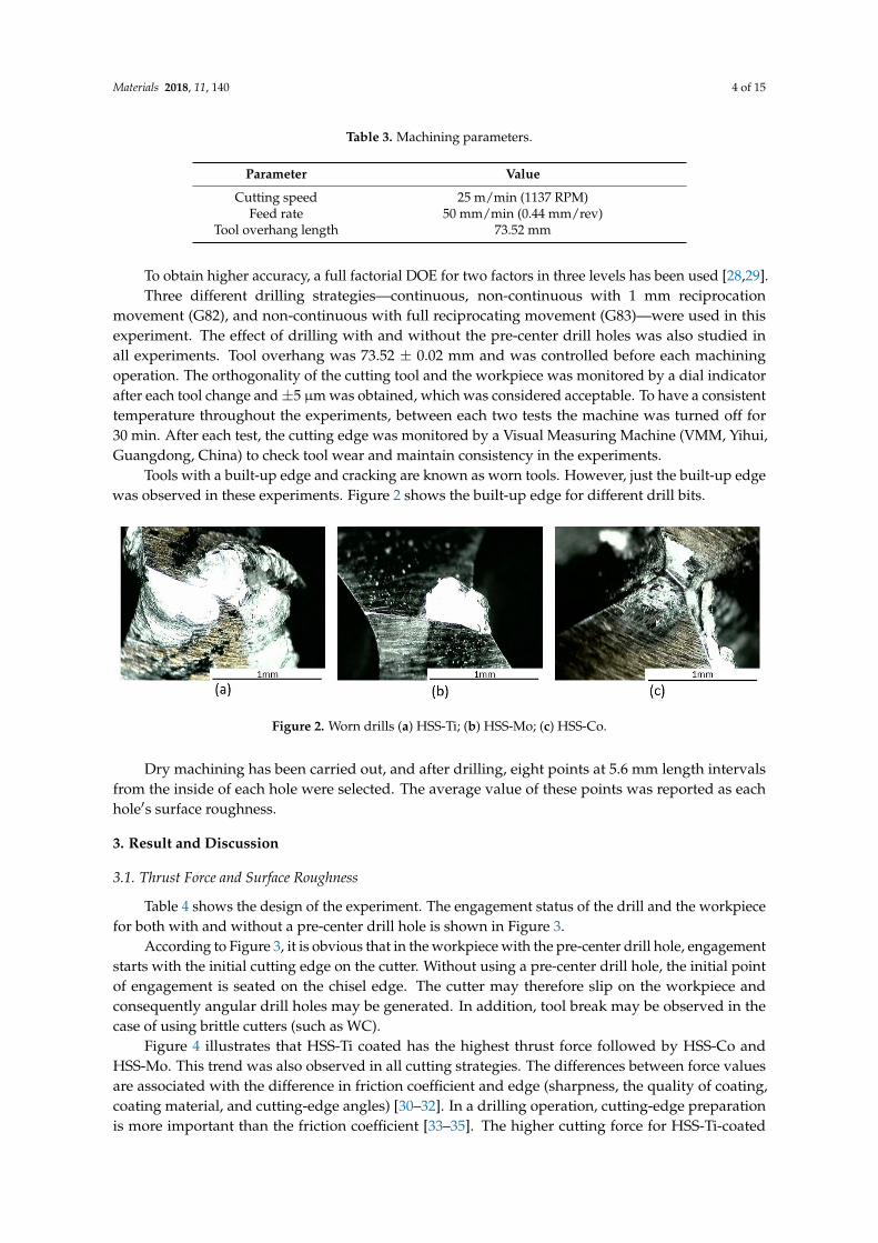
Tools with a built-up edge and cracking are known as worn tools. However, just the built-up edgewas observed in these experiments. Figure 2 shows the built-up edge for different drill bits.
Materials 2018, 11, 140 4 of 14
Three different drilling strategies—continuous, non-continuous with 1 mm reciprocation movement (G82), and non-continuous with full reciprocating movement (G83)—were used in this experiment. The effect of drilling with and without the pre-center drill holes was also studied in all experiments. Tool overhang was 73.52 ± 0.02 mm and was controlled before each machining operation. The orthogonality of the cutting tool and the workpiece was monitored by a dial indicator after each tool change and ±5 µm was obtained, which was considered acceptable. To have a consistent temperature throughout the experiments, between each two tests the machine was turned off for 30 min. After each test, the cutting edge was monitored by a Visual Measuring Machine (VMM, Yihui, Guangdong, China) to check tool wear and maintain consistency in the experiments.
Tools with a built-up edge and cracking are known as worn tools. However, just the built-up edge was observed in these experiments. Figure 2 shows the built-up edge for different drill bits.
Figure 2. Worn drills (a) HSS-Ti; (b) HSS-Mo; (c) HSS-Co.
Dry machining has been carried out, and after drilling, eight points at 5.6 mm length intervals from the inside of each hole were selected. The average value of these points was reported as each hole′s surface roughness.
3. Result and Discussion
3.1. Thrust Force and Surface Roughness
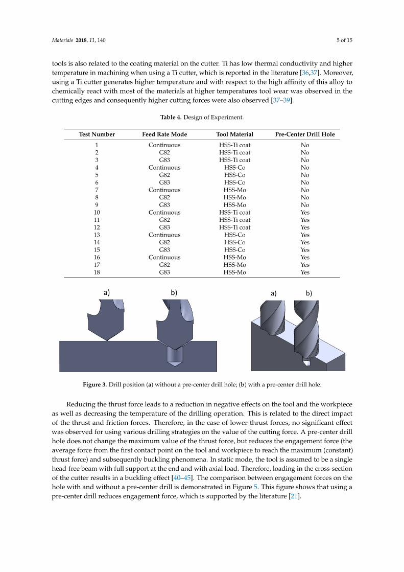
Table 4 shows the design of the experiment. The engagement status of the drill and the workpiece for both with and without a pre-center drill hole is shown in Figure 3.
Table 4. Design of Experiment.
Test Number Feed Rate Mode Tool Material Pre-Center Drill Hole 1 Continuous HSS-Ti coat No 2 G82 HSS-Ti coat No 3 G83 HSS-Ti coat No 4 Continuous HSS-Co No 5 G82 HSS-Co No 6 G83 HSS-Co No 7 Continuous HSS-Mo No 8 G82 HSS-Mo No 9 G83 HSS-Mo No 10 Continuous HSS-Ti coat Yes 11 G82 HSS-Ti coat Yes 12 G83 HSS-Ti coat Yes 13 Continuous HSS-Co Yes 14 G82 HSS-Co Yes 15 G83 HSS-Co Yes 16 Continuous HSS-Mo Yes 17 G82 HSS-Mo Yes 18 G83 HSS-Mo Yes
Figure 2. Worn drills (a) HSS-Ti; (b) HSS-Mo; (c) HSS-Co.
Dry machining has been carried out, and after drilling, eight points at 5.6 mm length intervalsfrom the inside of each hole were selected. The average value of these points was reported as eachhole′s surface roughness.
3. Result and Discussion
3.1. Thrust Force and Surface Roughness
Table 4 shows the design of the experiment. The engagement status of the drill and the workpiecefor both with and without a pre-center drill hole is shown in Figure 3.
According to Figure 3, it is obvious that in the workpiece with the pre-center drill hole, engagementstarts with the initial cutting edge on the cutter. Without using a pre-center drill hole, the initial pointof engagement is seated on the chisel edge. The cutter may therefore slip on the workpiece andconsequently angular drill holes may be generated. In addition, tool break may be observed in thecase of using brittle cutters (such as WC).
Figure 4 illustrates that HSS-Ti coated has the highest thrust force followed by HSS-Co andHSS-Mo. This trend was also observed in all cutting strategies. The differences between force valuesare associated with the difference in friction coefficient and edge (sharpness, the quality of coating,coating material, and cutting-edge angles) [30–32]. In a drilling operation, cutting-edge preparationis more important than the friction coefficient [33–35]. The higher cutting force for HSS-Ti-coated
Materials 2018, 11, 140 5 of 15
tools is also related to the coating material on the cutter. Ti has low thermal conductivity and highertemperature in machining when using a Ti cutter, which is reported in the literature [36,37]. Moreover,using a Ti cutter generates higher temperature and with respect to the high affinity of this alloy tochemically react with most of the materials at higher temperatures tool wear was observed in thecutting edges and consequently higher cutting forces were also observed [37–39].
Table 4. Design of Experiment.
Test Number Feed Rate Mode Tool Material Pre-Center Drill Hole
1 Continuous HSS-Ti coat No2 G82 HSS-Ti coat No3 G83 HSS-Ti coat No4 Continuous HSS-Co No5 G82 HSS-Co No6 G83 HSS-Co No7 Continuous HSS-Mo No8 G82 HSS-Mo No9 G83 HSS-Mo No
10 Continuous HSS-Ti coat Yes11 G82 HSS-Ti coat Yes12 G83 HSS-Ti coat Yes13 Continuous HSS-Co Yes14 G82 HSS-Co Yes15 G83 HSS-Co Yes16 Continuous HSS-Mo Yes17 G82 HSS-Mo Yes18 G83 HSS-Mo Yes
Materials 2018, 11, 140 5 of 14
According to Figure 3, it is obvious that in the workpiece with the pre-center drill hole, engagement starts with the initial cutting edge on the cutter. Without using a pre-center drill hole, the initial point of engagement is seated on the chisel edge. The cutter may therefore slip on the workpiece and consequently angular drill holes may be generated. In addition, tool break may be observed in the case of using brittle cutters (such as WC).
Figure 3. Drill position (a) without a pre-center drill hole; (b) with a pre-center drill hole.
Figure 4 illustrates that HSS-Ti coated has the highest thrust force followed by HSS-Co and HSS-Mo. This trend was also observed in all cutting strategies. The differences between force values are associated with the difference in friction coefficient and edge (sharpness, the quality of coating, coating material, and cutting-edge angles) [30–32]. In a drilling operation, cutting-edge preparation is more important than the friction coefficient [33–35]. The higher cutting force for HSS-Ti-coated tools is also related to the coating material on the cutter. Ti has low thermal conductivity and higher temperature in machining when using a Ti cutter, which is reported in the literature [36,37]. Moreover, using a Ti cutter generates higher temperature and with respect to the high affinity of this alloy to chemically react with most of the materials at higher temperatures tool wear was observed in the cutting edges and consequently higher cutting forces were also observed [37–39].
Figure 4. Cutting thrust force results for different cutters and strategies.
Reducing the thrust force leads to a reduction in negative effects on the tool and the workpiece as well as decreasing the temperature of the drilling operation. This is related to the direct impact of the thrust and friction forces. Therefore, in the case of lower thrust forces, no significant effect was observed for using various drilling strategies on the value of the cutting force. A pre-center drill hole does not change the maximum value of the thrust force, but reduces the engagement force (the average force from the first contact point on the tool and workpiece to reach the maximum (constant) thrust force) and subsequently buckling phenomena. In static mode, the tool is assumed to be a single
Figure 3. Drill position (a) without a pre-center drill hole; (b) with a pre-center drill hole.
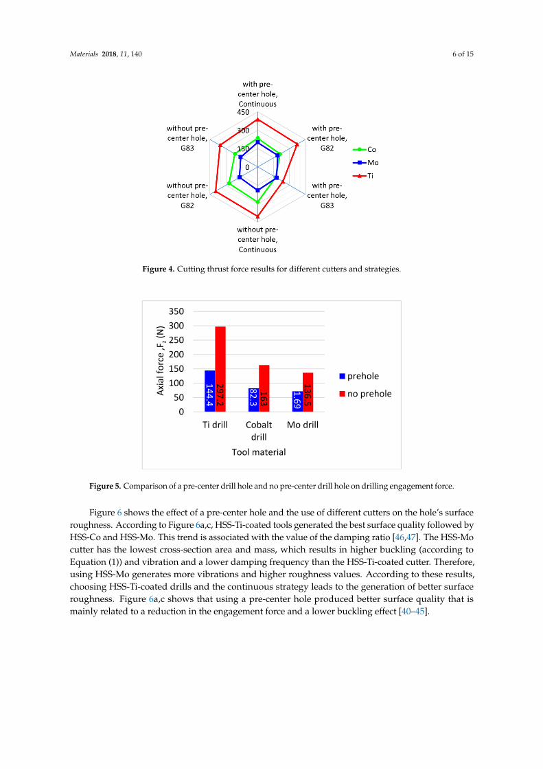
Reducing the thrust force leads to a reduction in negative effects on the tool and the workpieceas well as decreasing the temperature of the drilling operation. This is related to the direct impactof the thrust and friction forces. Therefore, in the case of lower thrust forces, no significant effectwas observed for using various drilling strategies on the value of the cutting force. A pre-center drillhole does not change the maximum value of the thrust force, but reduces the engagement force (theaverage force from the first contact point on the tool and workpiece to reach the maximum (constant)thrust force) and subsequently buckling phenomena. In static mode, the tool is assumed to be a singlehead-free beam with full support at the end and with axial load. Therefore, loading in the cross-sectionof the cutter results in a buckling effect [40–45]. The comparison between engagement forces on thehole with and without a pre-center drill is demonstrated in Figure 5. This figure shows that using apre-center drill reduces engagement force, which is supported by the literature [21].
Materials 2018, 11, 140 6 of 15
Materials 2018, 11, 140 5 of 14
According to Figure 3, it is obvious that in the workpiece with the pre-center drill hole, engagement starts with the initial cutting edge on the cutter. Without using a pre-center drill hole, the initial point of engagement is seated on the chisel edge. The cutter may therefore slip on the workpiece and consequently angular drill holes may be generated. In addition, tool break may be observed in the case of using brittle cutters (such as WC).
Figure 3. Drill position (a) without a pre-center drill hole; (b) with a pre-center drill hole.
Figure 4 illustrates that HSS-Ti coated has the highest thrust force followed by HSS-Co and HSS-Mo. This trend was also observed in all cutting strategies. The differences between force values are associated with the difference in friction coefficient and edge (sharpness, the quality of coating, coating material, and cutting-edge angles) [30–32]. In a drilling operation, cutting-edge preparation is more important than the friction coefficient [33–35]. The higher cutting force for HSS-Ti-coated tools is also related to the coating material on the cutter. Ti has low thermal conductivity and higher temperature in machining when using a Ti cutter, which is reported in the literature [36,37]. Moreover, using a Ti cutter generates higher temperature and with respect to the high affinity of this alloy to chemically react with most of the materials at higher temperatures tool wear was observed in the cutting edges and consequently higher cutting forces were also observed [37–39].
Figure 4. Cutting thrust force results for different cutters and strategies.
Reducing the thrust force leads to a reduction in negative effects on the tool and the workpiece as well as decreasing the temperature of the drilling operation. This is related to the direct impact of the thrust and friction forces. Therefore, in the case of lower thrust forces, no significant effect was observed for using various drilling strategies on the value of the cutting force. A pre-center drill hole does not change the maximum value of the thrust force, but reduces the engagement force (the average force from the first contact point on the tool and workpiece to reach the maximum (constant) thrust force) and subsequently buckling phenomena. In static mode, the tool is assumed to be a single
Figure 4. Cutting thrust force results for different cutters and strategies.
Materials 2018, 11, 140 6 of 14
head-free beam with full support at the end and with axial load. Therefore, loading in the cross-section of the cutter results in a buckling effect [40–45]. The comparison between engagement forces on the hole with and without a pre-center drill is demonstrated in Figure 5. This figure shows that using a pre-center drill reduces engagement force, which is supported by the literature [21].
Figure 5. Comparison of a pre-center drill hole and no pre-center drill hole on drilling engagement force.
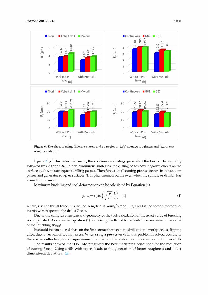
Figures 6 shows the effect of a pre-center hole and the use of different cutters on the hole’s surface roughness. According to Figure 6a,c, HSS-Ti-coated tools generated the best surface quality followed by HSS-Co and HSS-Mo. This trend is associated with the value of the damping ratio [46,47]. The HSS-Mo cutter has the lowest cross-section area and mass, which results in higher buckling (according to Equation (1)) and vibration and a lower damping frequency than the HSS-Ti-coated cutter. Therefore, using HSS-Mo generates more vibrations and higher roughness values. According to these results, choosing HSS-Ti-coated drills and the continuous strategy leads to the generation of better surface roughness. Figure 6a,c shows that using a pre-center hole produced better surface quality that is mainly related to a reduction in the engagement force and a lower buckling effect [40–45].
Figure 6b,d illustrates that using the continuous strategy generated the best surface quality followed by G83 and G82. In non-continuous strategies, the cutting edges have negative effects on the surface quality in subsequent drilling passes. Therefore, a small cutting process occurs in subsequent passes and generates rougher surfaces. This phenomenon occurs even when the spindle or drill bit has a small imbalance.
144.4
82.3
71.69
297.2
163
136.5
050
100150200250300350
Ti drill Cobaltdrill
Mo drill
Axia
l for
ce ,F
z(N
)
Tool material
prehole
no prehole
0
2
4
6
Without Pre-hole
With Pre-hole
3.46
6
2.87
4
3.69
1
3.40
34.41
0
3.65
3
R a(μ
m)
(a)
Ti drill Cobalt drill Mo drill
0
1
2
3
4
Without Pre-hole
With Pre-hole
3.68
1
3.04
93.94
9
3.56
5
3.93
7
3.31
5
R a (μ
m)
(b)
Continuous G82 G83
Figure 5. Comparison of a pre-center drill hole and no pre-center drill hole on drilling engagement force.
Figure 6 shows the effect of a pre-center hole and the use of different cutters on the hole’s surfaceroughness. According to Figure 6a,c, HSS-Ti-coated tools generated the best surface quality followed byHSS-Co and HSS-Mo. This trend is associated with the value of the damping ratio [46,47]. The HSS-Mocutter has the lowest cross-section area and mass, which results in higher buckling (according toEquation (1)) and vibration and a lower damping frequency than the HSS-Ti-coated cutter. Therefore,using HSS-Mo generates more vibrations and higher roughness values. According to these results,choosing HSS-Ti-coated drills and the continuous strategy leads to the generation of better surfaceroughness. Figure 6a,c shows that using a pre-center hole produced better surface quality that ismainly related to a reduction in the engagement force and a lower buckling effect [40–45].
Materials 2018, 11, 140 7 of 15
Materials 2018, 11, 140 6 of 14
head-free beam with full support at the end and with axial load. Therefore, loading in the cross-section of the cutter results in a buckling effect [40–45]. The comparison between engagement forces on the hole with and without a pre-center drill is demonstrated in Figure 5. This figure shows that using a pre-center drill reduces engagement force, which is supported by the literature [21].
Figure 5. Comparison of a pre-center drill hole and no pre-center drill hole on drilling engagement force.
Figures 6 shows the effect of a pre-center hole and the use of different cutters on the hole’s surface roughness. According to Figure 6a,c, HSS-Ti-coated tools generated the best surface quality followed by HSS-Co and HSS-Mo. This trend is associated with the value of the damping ratio [46,47]. The HSS-Mo cutter has the lowest cross-section area and mass, which results in higher buckling (according to Equation (1)) and vibration and a lower damping frequency than the HSS-Ti-coated cutter. Therefore, using HSS-Mo generates more vibrations and higher roughness values. According to these results, choosing HSS-Ti-coated drills and the continuous strategy leads to the generation of better surface roughness. Figure 6a,c shows that using a pre-center hole produced better surface quality that is mainly related to a reduction in the engagement force and a lower buckling effect [40–45].
Figure 6b,d illustrates that using the continuous strategy generated the best surface quality followed by G83 and G82. In non-continuous strategies, the cutting edges have negative effects on the surface quality in subsequent drilling passes. Therefore, a small cutting process occurs in subsequent passes and generates rougher surfaces. This phenomenon occurs even when the spindle or drill bit has a small imbalance.
144.4
82.3
71.69
297.2
163
136.5
050
100150200250300350
Ti drill Cobaltdrill
Mo drill
Axia
l for
ce ,F
z(N
)
Tool material
prehole
no prehole
0
2
4
6
Without Pre-hole
With Pre-hole
3.46
6
2.87
4
3.69
1
3.40
34.41
0
3.65
3
R a(μ
m)
(a)
Ti drill Cobalt drill Mo drill
0
1
2
3
4
Without Pre-hole
With Pre-hole
3.68
1
3.04
93.94
9
3.56
5
3.93
7
3.31
5
R a (μ
m)
(b)
Continuous G82 G83
Materials 2018, 11, 140 7 of 14
Figure 6. The effect of using different cutters and strategies on (a,b) average roughness and (c,d) mean roughness depth.
Maximum buckling and tool deformation can be calculated by Equation (1). = [sec . 2 − 1] (1)
where, P is the thrust force, L is the tool length, E is Young′s modulus, and I is the second moment of inertia with respect to the drill’s Z axis.
Due to the complex structure and geometry of the tool, calculation of the exact value of buckling is complicated. As shown in Equation (1), increasing the thrust force leads to an increase in the value of tool buckling (ymax).
It should be considered that, on the first contact between the drill and the workpiece, a slipping effect due to vertical offset may occur. When using a pre-center drill, this problem is solved because of the smaller cutter length and larger moment of inertia. This problem is more common in thinner drills.
The results showed that HSS-Mo presented the best machining conditions for the reduction of cutting force. Using drills with tapers leads to the generation of better roughness and lower dimensional deviations [48].
3.2. Geometrical Dimension and Tolerance
Cylindricity increased by using a pre-center drill hole for all experiments that are associated with reducing engagement force (Figure 5). According to Equation (1), forces P and L reduce and the value of I increases, therefore lower buckling and higher cylindricity were observed [40–45]. The best cylindricity was obtained when using HSS-Co tools, followed by HSS-Mo and HSS-Ti-coated tools. Figure 4 shows that Ti has the highest cutting force and buckling values and therefore the lowest cylindricity is related to higher vibration. In this experiment, due to using Al as a workpiece and the high hardness of the cutters comprising HSS-Ti: 856.4 Hv, HSS-Co: 910 Hv, and HSS-Mo: 667 Hv, no torsional vibration was observed on the workpiece and it is neglected. Vibrations with external loads are obtained from the following ordinary differential equation. M (t) + C (t) + K (t) = ⋜ + 2 + = (2)
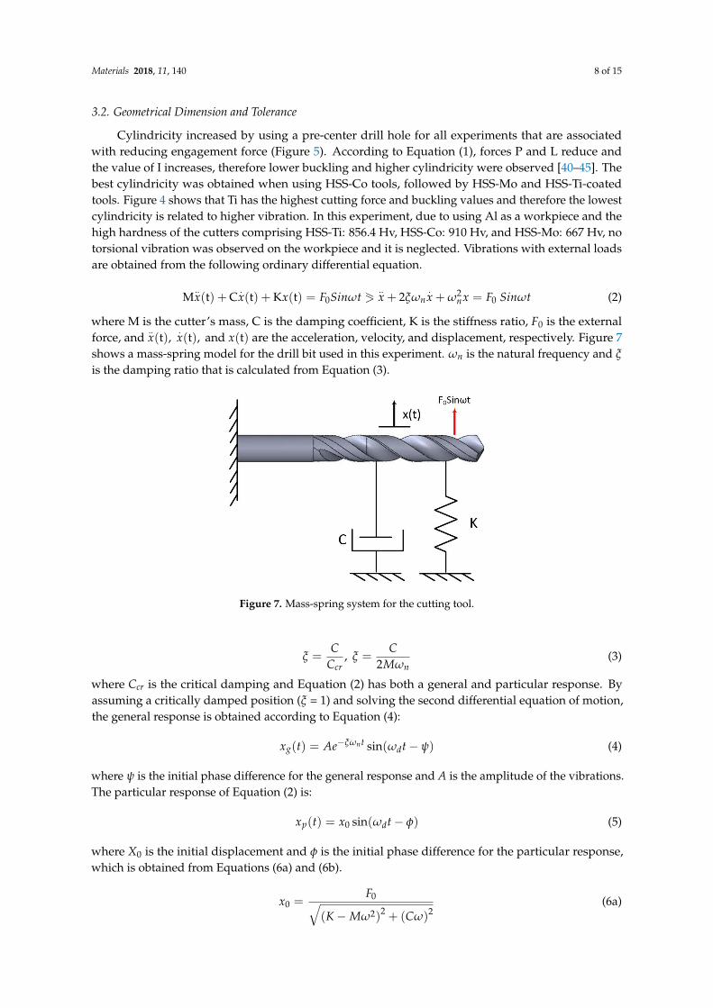
where M is the cutter’s mass, C is the damping coefficient, K is the stiffness ratio, F0 is the external force, and (t), (t), and (t) are the acceleration, velocity, and displacement, respectively. Figure 7 shows a mass-spring model for the drill bit used in this experiment. is the natural frequency and ξ is the damping ratio that is calculated from Equation (3).
0
10
20
30
Without Pre-hole
With Pre-hole
18.4
98
14.7
79
18.1
13
17.7
37
20.5
59
18.7
13
R z(μ
m)
(c)
Ti drill Cobalt drill Mo drill
0
10
20
30
Without Pre-hole
With Pre-hole17
.927
15.6
1320.1
75
18.5
04
19.0
67
17.1
12
R z (μm
)
(d)
Continuous G82 G83
Figure 6. The effect of using different cutters and strategies on (a,b) average roughness and (c,d) meanroughness depth.
Figure 6b,d illustrates that using the continuous strategy generated the best surface qualityfollowed by G83 and G82. In non-continuous strategies, the cutting edges have negative effects on thesurface quality in subsequent drilling passes. Therefore, a small cutting process occurs in subsequentpasses and generates rougher surfaces. This phenomenon occurs even when the spindle or drill bit hasa small imbalance.
Maximum buckling and tool deformation can be calculated by Equation (1).
ymax = e[sec(√
pEI· L2
)− 1] (1)
where, P is the thrust force, L is the tool length, E is Young′s modulus, and I is the second moment ofinertia with respect to the drill’s Z axis.
Due to the complex structure and geometry of the tool, calculation of the exact value of bucklingis complicated. As shown in Equation (1), increasing the thrust force leads to an increase in the valueof tool buckling (ymax).
It should be considered that, on the first contact between the drill and the workpiece, a slippingeffect due to vertical offset may occur. When using a pre-center drill, this problem is solved because ofthe smaller cutter length and larger moment of inertia. This problem is more common in thinner drills.
The results showed that HSS-Mo presented the best machining conditions for the reductionof cutting force. Using drills with tapers leads to the generation of better roughness and lowerdimensional deviations [48].
Materials 2018, 11, 140 8 of 15
3.2. Geometrical Dimension and Tolerance
Cylindricity increased by using a pre-center drill hole for all experiments that are associatedwith reducing engagement force (Figure 5). According to Equation (1), forces P and L reduce andthe value of I increases, therefore lower buckling and higher cylindricity were observed [40–45]. Thebest cylindricity was obtained when using HSS-Co tools, followed by HSS-Mo and HSS-Ti-coatedtools. Figure 4 shows that Ti has the highest cutting force and buckling values and therefore the lowestcylindricity is related to higher vibration. In this experiment, due to using Al as a workpiece and thehigh hardness of the cutters comprising HSS-Ti: 856.4 Hv, HSS-Co: 910 Hv, and HSS-Mo: 667 Hv, notorsional vibration was observed on the workpiece and it is neglected. Vibrations with external loadsare obtained from the following ordinary differential equation.
M..x(t) + C
.x(t) + Kx(t) = F0Sinωt 1
..x + 2ξωn
.x + ω2
nx = F0 Sinωt (2)
where M is the cutter’s mass, C is the damping coefficient, K is the stiffness ratio, F0 is the externalforce, and
..x(t),
.x(t), and x(t) are the acceleration, velocity, and displacement, respectively. Figure 7
shows a mass-spring model for the drill bit used in this experiment. ωn is the natural frequency and ξ
is the damping ratio that is calculated from Equation (3).Materials 2018, 11, 140 8 of 14
Figure 7. Mass-spring system for the cutting tool.
= , = 2 (3)
where Ccr is the critical damping and Equation (2) has both a general and particular response. By assuming a critically damped position (ξ = 1) and solving the second differential equation of motion, the general response is obtained according to Equation (4): ( ) = sin( − ) (4)
where ψ is the initial phase difference for the general response and A is the amplitude of the vibrations. The particular response of Equation (2) is: ( ) = sin( − ) (5)
where X0 is the initial displacement and is the initial phase difference for the particular response, which is obtained from Equations (6a) and (6b). = ( − ) + ( ) (6a)
= tan − (6b)
Based on the following relations, Equations (6a) and (6b) are converted to a dimensionless quantity: = 11 − + [2 ]
(7a)
= tan 21 − . (7b)
In our experiments, the initial conditions are, x(0) = 0 and (0) = 0, so by determining Equations (5)–(7), the particular response is obtained from Equation (8). ( ) ≅ 12 [ 1 − + − ] (8)
In this experiment, due to using cutting tools with a high value of hardness ≈ 0
and assuming = and = , the particular response is:
Figure 7. Mass-spring system for the cutting tool.
ξ =C
Ccr, ξ =
C2Mωn
(3)
where Ccr is the critical damping and Equation (2) has both a general and particular response. Byassuming a critically damped position (ξ = 1) and solving the second differential equation of motion,the general response is obtained according to Equation (4):
xg(t) = Ae−ξωnt sin(ωdt− ψ) (4)
where ψ is the initial phase difference for the general response and A is the amplitude of the vibrations.The particular response of Equation (2) is:
xp(t) = x0 sin(ωdt− φ) (5)
where X0 is the initial displacement and φ is the initial phase difference for the particular response,which is obtained from Equations (6a) and (6b).
x0 =F0√
(K−Mω2)2 + (Cω)2
(6a)
Materials 2018, 11, 140 9 of 15
φ = tan−1 Cω
K−Mω2 (6b)
Based on the following relations, Equations (6a) and (6b) are converted to a dimensionless quantity:
Kx0
F0=
1√[1−
(ωωn
)2]2
+ [2ξ ωωn
]2
(7a)
φ = tan−1 2ξ ωωn
1−(
ωωn
)2 . (7b)
In our experiments, the initial conditions are, x(0) = 0 and.x(0) = 0, so by determining
Equations (5)–(7), the particular response is obtained from Equation (8).
x(t) ∼=1
2ξ
F0
K[e−ξωnt
(ξ√
1− ξ2sinωdt + cosωdt
)− cosωnt] (8)
In this experiment, due to using cutting tools with a high value of hardness ξ√1−ξ2
sinωdt ≈ 0 and
assuming ωn = ωd and φ = π2 , the particular response is:
x(t) ∼=1
2ξ
F0
K
(e−ξωnt − 1
)cosωnt. (9)
According to Equation (9), the amplitude of the vibrations is a function of force, and whenusing HSS-Ti tools a higher force was captured; therefore, by increasing F0 in the right-hand side ofEquation (9), the value of x(t) will increase and cylindricity will decrease. This tool is heavier thanHSS-Mo; however, due to the higher effect of the cutting force on the vibration compared to the impactof the cutter weight, HSS-Ti generates poorer cylindricity.
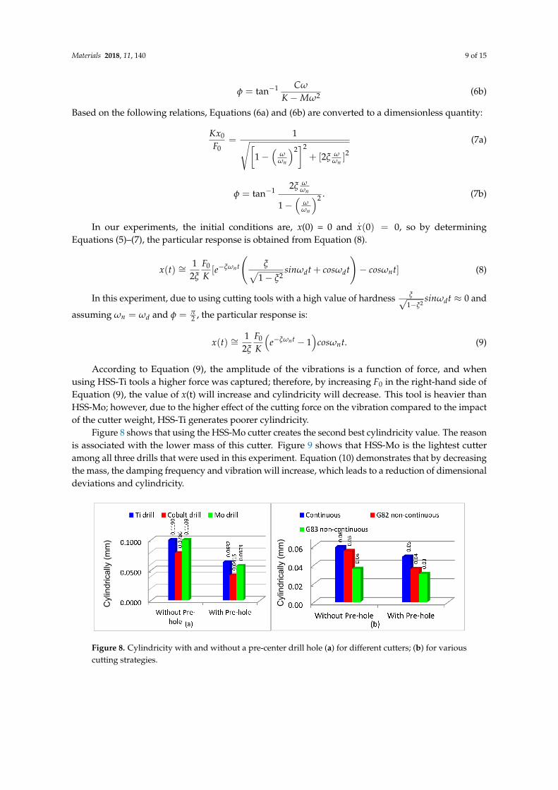
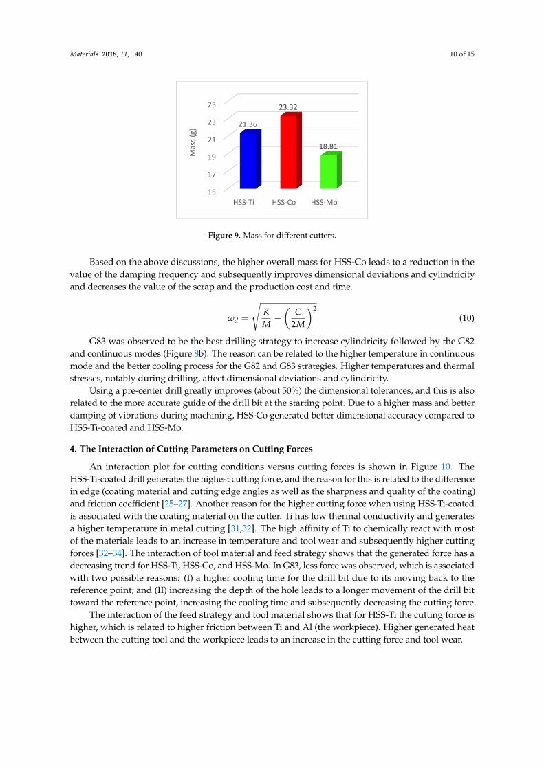
Figure 8 shows that using the HSS-Mo cutter creates the second best cylindricity value. The reasonis associated with the lower mass of this cutter. Figure 9 shows that HSS-Mo is the lightest cutteramong all three drills that were used in this experiment. Equation (10) demonstrates that by decreasingthe mass, the damping frequency and vibration will increase, which leads to a reduction of dimensionaldeviations and cylindricity.
Materials 2018, 11, 140 9 of 14
( ) ≅ 12 − 1 . (9)
According to Equation (9), the amplitude of the vibrations is a function of force, and when using HSS-Ti tools a higher force was captured; therefore, by increasing F0 in the right-hand side of Equation (9), the value of x(t) will increase and cylindricity will decrease. This tool is heavier than HSS-Mo; however, due to the higher effect of the cutting force on the vibration compared to the impact of the cutter weight, HSS-Ti generates poorer cylindricity.
Figure 8 shows that using the HSS-Mo cutter creates the second best cylindricity value. The reason is associated with the lower mass of this cutter. Figure 9 shows that HSS-Mo is the lightest cutter among all three drills that were used in this experiment. Equation (10) demonstrates that by decreasing the mass, the damping frequency and vibration will increase, which leads to a reduction of dimensional deviations and cylindricity.
Based on the above discussions, the higher overall mass for HSS-Co leads to a reduction in the value of the damping frequency and subsequently improves dimensional deviations and cylindricity and decreases the value of the scrap and the production cost and time.
= − 2 (10)
Figure 8. Cylindricity with and without a pre-center drill hole (a) for different cutters; (b) for various cutting strategies.
G83 was observed to be the best drilling strategy to increase cylindricity followed by the G82 and continuous modes (Figure 8b). The reason can be related to the higher temperature in continuous mode and the better cooling process for the G82 and G83 strategies. Higher temperatures and thermal stresses, notably during drilling, affect dimensional deviations and cylindricity.
Figure 9. Mass for different cutters.
15
17
19
21
23
25
HSS-Ti HSS-Co HSS-Mo
21.36
23.32
18.81
Mas
s (g)
Cyl
indr
ical
ly (m
m)
Cyl
indr
ical
ly (m
m)
Figure 8. Cylindricity with and without a pre-center drill hole (a) for different cutters; (b) for variouscutting strategies.
Materials 2018, 11, 140 10 of 15
Materials 2018, 11, 140 9 of 14
( ) ≅ 12 − 1 . (9)
According to Equation (9), the amplitude of the vibrations is a function of force, and when using HSS-Ti tools a higher force was captured; therefore, by increasing F0 in the right-hand side of Equation (9), the value of x(t) will increase and cylindricity will decrease. This tool is heavier than HSS-Mo; however, due to the higher effect of the cutting force on the vibration compared to the impact of the cutter weight, HSS-Ti generates poorer cylindricity.
Figure 8 shows that using the HSS-Mo cutter creates the second best cylindricity value. The reason is associated with the lower mass of this cutter. Figure 9 shows that HSS-Mo is the lightest cutter among all three drills that were used in this experiment. Equation (10) demonstrates that by decreasing the mass, the damping frequency and vibration will increase, which leads to a reduction of dimensional deviations and cylindricity.
Based on the above discussions, the higher overall mass for HSS-Co leads to a reduction in the value of the damping frequency and subsequently improves dimensional deviations and cylindricity and decreases the value of the scrap and the production cost and time.
= − 2 (10)
Figure 8. Cylindricity with and without a pre-center drill hole (a) for different cutters; (b) for various cutting strategies.
G83 was observed to be the best drilling strategy to increase cylindricity followed by the G82 and continuous modes (Figure 8b). The reason can be related to the higher temperature in continuous mode and the better cooling process for the G82 and G83 strategies. Higher temperatures and thermal stresses, notably during drilling, affect dimensional deviations and cylindricity.
Figure 9. Mass for different cutters.
15
17
19
21
23
25
HSS-Ti HSS-Co HSS-Mo
21.36
23.32
18.81
Mas
s (g)
Cyl
indr
ical
ly (m
m)
Cyl
indr
ical
ly (m
m)
Figure 9. Mass for different cutters.
Based on the above discussions, the higher overall mass for HSS-Co leads to a reduction in thevalue of the damping frequency and subsequently improves dimensional deviations and cylindricityand decreases the value of the scrap and the production cost and time.
ωd =
√KM−(
C2M
)2(10)
G83 was observed to be the best drilling strategy to increase cylindricity followed by the G82and continuous modes (Figure 8b). The reason can be related to the higher temperature in continuousmode and the better cooling process for the G82 and G83 strategies. Higher temperatures and thermalstresses, notably during drilling, affect dimensional deviations and cylindricity.
Using a pre-center drill greatly improves (about 50%) the dimensional tolerances, and this is alsorelated to the more accurate guide of the drill bit at the starting point. Due to a higher mass and betterdamping of vibrations during machining, HSS-Co generated better dimensional accuracy compared toHSS-Ti-coated and HSS-Mo.
4. The Interaction of Cutting Parameters on Cutting Forces
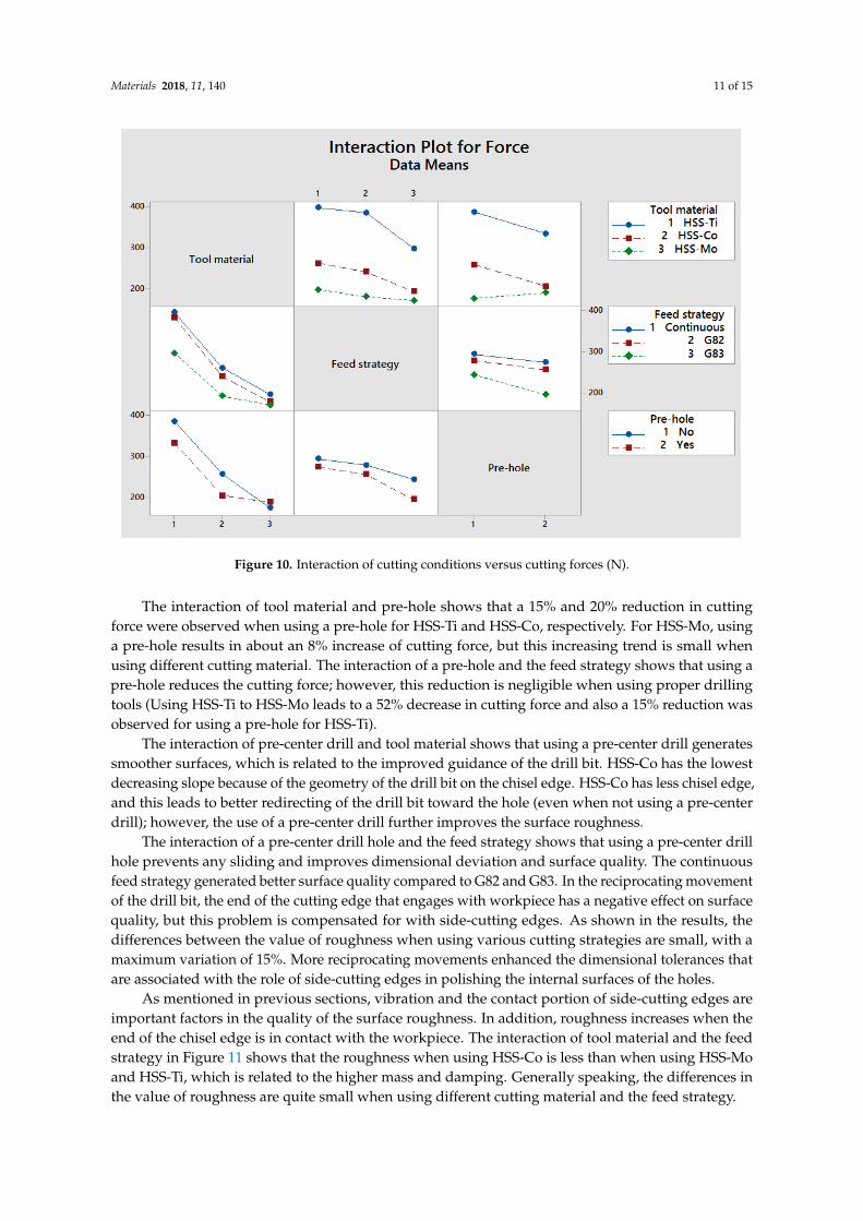
An interaction plot for cutting conditions versus cutting forces is shown in Figure 10. TheHSS-Ti-coated drill generates the highest cutting force, and the reason for this is related to the differencein edge (coating material and cutting edge angles as well as the sharpness and quality of the coating)and friction coefficient [25–27]. Another reason for the higher cutting force when using HSS-Ti-coatedis associated with the coating material on the cutter. Ti has low thermal conductivity and generatesa higher temperature in metal cutting [31,32]. The high affinity of Ti to chemically react with mostof the materials leads to an increase in temperature and tool wear and subsequently higher cuttingforces [32–34]. The interaction of tool material and feed strategy shows that the generated force has adecreasing trend for HSS-Ti, HSS-Co, and HSS-Mo. In G83, less force was observed, which is associatedwith two possible reasons: (I) a higher cooling time for the drill bit due to its moving back to thereference point; and (II) increasing the depth of the hole leads to a longer movement of the drill bittoward the reference point, increasing the cooling time and subsequently decreasing the cutting force.
The interaction of the feed strategy and tool material shows that for HSS-Ti the cutting force ishigher, which is related to higher friction between Ti and Al (the workpiece). Higher generated heatbetween the cutting tool and the workpiece leads to an increase in the cutting force and tool wear.
Materials 2018, 11, 140 11 of 15
Materials 2018, 11, 140 10 of 14
Using a pre-center drill greatly improves (about 50%) the dimensional tolerances, and this is also related to the more accurate guide of the drill bit at the starting point. Due to a higher mass and better damping of vibrations during machining, HSS-Co generated better dimensional accuracy compared to HSS-Ti-coated and HSS-Mo.
4. The Interaction of Cutting Parameters on Cutting Forces
An interaction plot for cutting conditions versus cutting forces is shown in Figure 10. The HSS-Ti-coated drill generates the highest cutting force, and the reason for this is related to the difference in edge (coating material and cutting edge angles as well as the sharpness and quality of the coating) and friction coefficient [25–27]. Another reason for the higher cutting force when using HSS-Ti-coated is associated with the coating material on the cutter. Ti has low thermal conductivity and generates a higher temperature in metal cutting [31,32]. The high affinity of Ti to chemically react with most of the materials leads to an increase in temperature and tool wear and subsequently higher cutting forces [32–34]. The interaction of tool material and feed strategy shows that the generated force has a decreasing trend for HSS-Ti, HSS-Co, and HSS-Mo. In G83, less force was observed, which is associated with two possible reasons: (I) a higher cooling time for the drill bit due to its moving back to the reference point; and (II) increasing the depth of the hole leads to a longer movement of the drill bit toward the reference point, increasing the cooling time and subsequently decreasing the cutting force.
The interaction of the feed strategy and tool material shows that for HSS-Ti the cutting force is higher, which is related to higher friction between Ti and Al (the workpiece). Higher generated heat between the cutting tool and the workpiece leads to an increase in the cutting force and tool wear.
The interaction of tool material and pre-hole shows that a 15% and 20% reduction in cutting force were observed when using a pre-hole for HSS-Ti and HSS-Co, respectively. For HSS-Mo, using a pre-hole results in about an 8% increase of cutting force, but this increasing trend is small when using different cutting material. The interaction of a pre-hole and the feed strategy shows that using a pre-hole reduces the cutting force; however, this reduction is negligible when using proper drilling tools (Using HSS-Ti to HSS-Mo leads to a 52% decrease in cutting force and also a 15% reduction was observed for using a pre-hole for HSS-Ti).
Figure 10. Interaction of cutting conditions versus cutting forces (N). Figure 10. Interaction of cutting conditions versus cutting forces (N).
The interaction of tool material and pre-hole shows that a 15% and 20% reduction in cuttingforce were observed when using a pre-hole for HSS-Ti and HSS-Co, respectively. For HSS-Mo, usinga pre-hole results in about an 8% increase of cutting force, but this increasing trend is small whenusing different cutting material. The interaction of a pre-hole and the feed strategy shows that using apre-hole reduces the cutting force; however, this reduction is negligible when using proper drillingtools (Using HSS-Ti to HSS-Mo leads to a 52% decrease in cutting force and also a 15% reduction wasobserved for using a pre-hole for HSS-Ti).
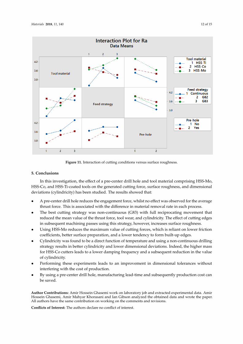
The interaction of pre-center drill and tool material shows that using a pre-center drill generatessmoother surfaces, which is related to the improved guidance of the drill bit. HSS-Co has the lowestdecreasing slope because of the geometry of the drill bit on the chisel edge. HSS-Co has less chisel edge,and this leads to better redirecting of the drill bit toward the hole (even when not using a pre-centerdrill); however, the use of a pre-center drill further improves the surface roughness.
The interaction of a pre-center drill hole and the feed strategy shows that using a pre-center drillhole prevents any sliding and improves dimensional deviation and surface quality. The continuousfeed strategy generated better surface quality compared to G82 and G83. In the reciprocating movementof the drill bit, the end of the cutting edge that engages with workpiece has a negative effect on surfacequality, but this problem is compensated for with side-cutting edges. As shown in the results, thedifferences between the value of roughness when using various cutting strategies are small, with amaximum variation of 15%. More reciprocating movements enhanced the dimensional tolerances thatare associated with the role of side-cutting edges in polishing the internal surfaces of the holes.
As mentioned in previous sections, vibration and the contact portion of side-cutting edges areimportant factors in the quality of the surface roughness. In addition, roughness increases when theend of the chisel edge is in contact with the workpiece. The interaction of tool material and the feedstrategy in Figure 11 shows that the roughness when using HSS-Co is less than when using HSS-Moand HSS-Ti, which is related to the higher mass and damping. Generally speaking, the differences inthe value of roughness are quite small when using different cutting material and the feed strategy.
Materials 2018, 11, 140 12 of 15
Materials 2018, 11, 140 11 of 14
The interaction of pre-center drill and tool material shows that using a pre-center drill generates smoother surfaces, which is related to the improved guidance of the drill bit. HSS-Co has the lowest decreasing slope because of the geometry of the drill bit on the chisel edge. HSS-Co has less chisel edge, and this leads to better redirecting of the drill bit toward the hole (even when not using a pre-center drill); however, the use of a pre-center drill further improves the surface roughness.
The interaction of a pre-center drill hole and the feed strategy shows that using a pre-center drill hole prevents any sliding and improves dimensional deviation and surface quality. The continuous feed strategy generated better surface quality compared to G82 and G83. In the reciprocating movement of the drill bit, the end of the cutting edge that engages with workpiece has a negative effect on surface quality, but this problem is compensated for with side-cutting edges. As shown in the results, the differences between the value of roughness when using various cutting strategies are small, with a maximum variation of 15%. More reciprocating movements enhanced the dimensional tolerances that are associated with the role of side-cutting edges in polishing the internal surfaces of the holes.
As mentioned in previous sections, vibration and the contact portion of side-cutting edges are important factors in the quality of the surface roughness. In addition, roughness increases when the end of the chisel edge is in contact with the workpiece. The interaction of tool material and the feed strategy in Figure 11 shows that the roughness when using HSS-Co is less than when using HSS-Mo and HSS-Ti, which is related to the higher mass and damping. Generally speaking, the differences in the value of roughness are quite small when using different cutting material and the feed strategy.
Figure 11. Interaction of cutting conditions versus surface roughness.
5. Conclusions
In this investigation, the effect of a pre-center drill hole and tool material comprising HSS-Mo, HSS-Co, and HSS-Ti-coated tools on the generated cutting force, surface roughness, and dimensional deviations (cylindricity) has been studied. The results showed that:
A pre-center drill hole reduces the engagement force, whilst no effect was observed for the average thrust force. This is associated with the difference in material removal rate in each process.
Figure 11. Interaction of cutting conditions versus surface roughness.
5. Conclusions
In this investigation, the effect of a pre-center drill hole and tool material comprising HSS-Mo,HSS-Co, and HSS-Ti-coated tools on the generated cutting force, surface roughness, and dimensionaldeviations (cylindricity) has been studied. The results showed that:
• A pre-center drill hole reduces the engagement force, whilst no effect was observed for the averagethrust force. This is associated with the difference in material removal rate in each process.
• The best cutting strategy was non-continuous (G83) with full reciprocating movement thatreduced the mean value of the thrust force, tool wear, and cylindricity. The effect of cutting edgesin subsequent machining passes using this strategy, however, increases surface roughness.
• Using HSS-Mo reduces the maximum value of cutting forces, which is reliant on lower frictioncoefficients, better surface preparation, and a lower tendency to form built-up edges.
• Cylindricity was found to be a direct function of temperature and using a non-continuous drillingstrategy results in better cylindricity and lower dimensional deviations. Indeed, the higher massfor HSS-Co cutters leads to a lower damping frequency and a subsequent reduction in the valueof cylindricity.
• Performing these experiments leads to an improvement in dimensional tolerances withoutinterfering with the cost of production.
• By using a pre-center drill hole, manufacturing lead-time and subsequently production cost canbe saved.
Author Contributions: Amir Hossein Ghasemi work on laboratory job and extracted experimental data. AmirHossein Ghasemi, Amir Mahyar Khorasani and Ian Gibson analyzed the obtained data and wrote the paper.All authors have the same contribution on working on the comments and revisions.
Conflicts of Interest: The authors declare no conflict of interest.
Materials 2018, 11, 140 13 of 15
References
1. Giasin, K.; Ayvar-Soberanis, S. Evaluation of Workpiece Temperature during Drilling of GLARE Fiber MetalLaminates Using Infrared Techniques: Effect of Cutting Parameters, Fiber Orientation and Spray MistApplication. Materials 2016, 9, 622. [CrossRef] [PubMed]
2. Ramulu, M.; Spaulding, M. Drilling of Hybrid Titanium Composite Laminate (HTCL) with ElectricalDischarge Machining. Materials 2016, 9, 746. [CrossRef] [PubMed]
3. Rezende, B.; Silveira, M.L.; Vieira, L.M.G.; Abrão, A.M.; Faria, P.E.; Rubio, J.C.C. Investigation on the Effectof Drill Geometry and Pilot Holes on Thrust Force and Burr Height When Drilling an Aluminium/PESandwich Material. Materials 2016, 9, 774. [CrossRef] [PubMed]
4. Choi, W.; Kim, H.Y.; Jeon, J.W.; Chang, W.S.; Cho, S.-H. Vibration-Assisted Femtosecond Laser Drilling withControllable Taper Angles for AMOLED Fine Metal Mask Fabrication. Materials 2017, 10, 212. [CrossRef][PubMed]
5. Chowdhury, M.; Ullah, A.S.; Anwar, S. Drilling High Precision Holes in Ti6Al4V Using Rotary UltrasonicMachining and Uncertainties Underlying Cutting Force, Tool Wear, and Production Inaccuracies. Materials2017, 10, 1069. [CrossRef] [PubMed]
6. Klocke, F.; Krieg, T. Coated tools for metal cutting–features and applications. CIRP Ann. Manuf. Technol.1999, 48, 515–525. [CrossRef]
7. Kelly, J.; Cotterell, M. Minimal lubrication machining of aluminium alloys. J. Mater. Process. Technol. 2002,120, 327–334. [CrossRef]
8. Tsao, C.; Hocheng, H. The effect of chisel length and associated pilot hole on delamination when drillingcomposite materials. Int. J. Mach. Tools Manuf. 2003, 43, 1087–1092. [CrossRef]
9. Paro, J.; Gustafsson, T.; Koskinen, J. Drilling of X2CrNi 19 11 stainless steel with hiped NiTi coating. J. Mater.Process. Technol. 2004, 150, 309–316. [CrossRef]
10. Bakkal, M.; Shih, A.J.; McSpadden, S.B.; Scattergood, R.O. Thrust force, torque, and tool wear in drilling thebulk metallic glass. Int. J. Mach. Tools Manuf. 2005, 45, 863–872. [CrossRef]
11. Astakhov, V.P.; Galitsky, V.V. Tool life testing in gundrilling: An application of the group method of datahandling (GMDH). Int. J. Mach. Tools Manuf. 2005, 45, 509–517. [CrossRef]
12. Bagci, E.; Ozcelik, B. Analysis of temperature changes on the twist drill under different drilling conditionsbased on Taguchi method during dry drilling of Al 7075-T651. Int. J. Adv. Manuf. Technol. 2006, 29, 629–636.[CrossRef]
13. Ke, F.; Ni, J.; Stephenson, D. Chip thickening in deep-hole drilling. Int. J. Mach. Tools Manuf. 2006, 46,1500–1507. [CrossRef]
14. Hocheng, H.; Tsao, C. Effects of special drill bits on drilling-induced delamination of composite materials.Int. J. Mach. Tools Manuf. 2006, 46, 1403–1416. [CrossRef]
15. Lazar, M.-B.; Xirouchakis, P. Mechanical load distribution along the main cutting edges in drilling. J. Mater.Process. Technol. 2013, 213, 245–260. [CrossRef]
16. Taskesen, A.; Kütükde, K. Experimental investigation and multi-objective analysis on drilling of boroncarbide reinforced metal matrix composites using grey relational analysis. Measurement 2014, 47, 321–330.[CrossRef]
17. Olovsjö, S.; Wretland, A.; Sjöberg, G. The effect of grain size and hardness of wrought Alloy 718 on the wearof cemented carbide tools. Wear 2010, 268, 1045–1052. [CrossRef]
18. Sun, D.; Lemoine, P.; Keys, D.; Doyle, P.; Malinov, S.; Zhao, Q.; Qin, X.; Jin, Y. Hole-making processes andtheir impacts on the microstructure and fatigue response of aircraft alloys. Int. J. Adv. Manuf. Technol. 2016,1–8. [CrossRef]
19. Li, Z.; Zhang, D.; Jiang, X.; Geng, D. Study on rotary ultrasonic-assisted drilling of titanium alloys (Ti6Al4V)using 8-facet drill under no cooling condition. Int. J. Adv. Manuf. Technol. 2017, 90, 3249–3264. [CrossRef]
20. Voss, R.; Henerichs, M.; Harsch, D.; Kuster, F.; Wegener, K. Optimised approach for characterisation ofcutting edge micro-geometry in drilling carbon fibre reinforced plastics(CFRP). Int. J. Adv. Manuf. Technol.2017, 90, 457–472. [CrossRef]
21. Kouam, J.; Djebara, A.; Songmene, V. Experimental investigation on the effect of pre-holes on drilling processperformance of aluminum alloys: Forces, surface finish and dust emission. Adv. Mater. Sci. Appl. 2014, 3,13–23. [CrossRef]
Materials 2018, 11, 140 14 of 15
22. Nieslony, P.; Cichosz, P.; Krolczyk, G.M.; Legutko, S.; Smyczek, D.; Kolodziej, M. Experimental studies ofthe cutting force and surface morphology of explosively clad Ti–steel plates. Measurement 2016, 78, 129–137.[CrossRef]
23. Nieslony, P.; Krolczyk, G.M.; Zak, K.; Maruda, R.W.; Legutko, S. Comparative assessment of the mechanicaland electromagnetic surfaces of explosively clad Ti–steel plates after drilling process. Precis. Eng. 2017, 47,104–110. [CrossRef]
24. Percin, M.; Aslantas, K.; Ucun, I.; Kaynak, Y.; Çicek, A. Micro-drilling of Ti–6Al–4V alloy: The effects ofcooling/lubricating. Precis. Eng. 2016, 45, 450–462. [CrossRef]
25. Berzosa, F.; de Agustina, B.; Rubio, E. Tool Selection in Drilling of Magnesium UNSM11917 Pieces underDry and MQL Conditions Based on Surface Roughness. Procedia Eng. 2017, 184, 117–127. [CrossRef]
26. Azghandi, B.V.; Kadivar, M.; Razfar, M. An Experimental Study on Cutting Forces in Ultrasonic AssistedDrilling. Procedia CIRP 2016, 46, 563–566. [CrossRef]
27. Chatterjee, S.; Mahapatra, S.S.; Abhishek, K. Simulation and optimization of machining parameters indrilling of titanium alloys. Simul. Model. Pract. Theory 2016, 62, 31–48. [CrossRef]
28. Gaaz, T.S.; Sulong, A.B.; Kadhum, A.A.H.; Nassir, M.H.; Al-Amiery, A.A. Optimizing Injection MoldingParameters of Different Halloysites Type-Reinforced Thermoplastic Polyurethane Nanocomposites viaTaguchi Complemented with ANOVA. Materials 2016, 9, 947. [CrossRef] [PubMed]
29. Chen, H.-J.; Chang, S.-N.; Tang, C.-W. Application of the Taguchi Method for Optimizing the ProcessParameters of Producing Lightweight Aggregates by Incorporating Tile Grinding Sludge with ReservoirSediments. Materials 2017, 10, 1294. [CrossRef] [PubMed]
30. Abrão, A.M.; Rubio, J.C.C.; Faria, P.E.; Davim, J.P. The effect of cutting tool geometry on thrust force anddelamination when drilling glass fibre reinforced plastic composite. Mater. Des. 2008, 29, 508–513. [CrossRef]
31. Lucca, D.A.; Seo, Y.W.; Komanduri, R. Effect of Tool Edge Geometry on Energy Dissipation in UltraprecisionMachining. CIRP Ann. Manuf. Technol. 1993, 42, 83–86. [CrossRef]
32. Saglam, H.; Yaldiz, S.; Unsacar, F. The effect of tool geometry and cutting speed on main cutting force andtool tip temperature. Mater. Des. 2007, 28, 101–111. [CrossRef]
33. Ramesh, V. Cutting edge preparation. In Proceedings of the 9th IFR International Conference, Indianapolis,IN, USA, 24–28 March 2014.
34. Özel, T. Modeling of hard part machining: Effect of insert edge preparation in CBN cutting tools. J. Mater.Process. Technol. 2003, 141, 284–293. [CrossRef]
35. Özel, T.; Hsu, T.-K.; Zeren, E. Effects of cutting edge geometry, workpiece hardness, feed rate and cuttingspeed on surface roughness and forces in finish turning of hardened AISI H13 steel. Int. J. Adv. Manuf.Technol. 2005, 25, 262–269. [CrossRef]
36. Davim, J.P. Machining of Titanium Alloys; Springer: Berlin/Heidelberg, Germany, 2014.37. Ezugwu, E.; Wang, Z. Titanium alloys and their machinability—A review. J. Mater. Process. Technol. 1997, 68,
262–274. [CrossRef]38. Khorasani, A.M.; Goldberg, M.; Doeven, E.H.; Littlefair, G. Titanium in Biomedical Applications—Properties
and Fabrication: A Review. J. Biomater. Tissue Eng. 2015, 5, 593–619. [CrossRef]39. Khorasani, A.M.; Gibson, L.; Goldberg, M.; Nornani, J.; Littlefair, G. Machinability of Metallic and Ceramic
Biomaterials: A review. Sci. Adv. Mater. 2016, 8, 1491–1511. [CrossRef]40. Schmitz, T.L.; Donalson, R. Predicting high-speed machining dynamics by substructure analysis. CIRP Ann.
Manuf. Technol. 2000, 49, 303–308. [CrossRef]41. Davies, M.A.; Kennedy, M.D. Tool point frequency response prediction for high-speed machining by RCSA.
J. Manuf. Sci. Eng. 2001, 123, 700–707.42. Schmitz, T.; Davies, M.A.; Snyder, J. Improving high-speed machining material removal rates by rapid
dynamic analysis. CIRP Ann. Manuf. Technol. 2001, 50, 263–268. [CrossRef]43. Schmitz, T.; Burns, T. Receptance Coupling for High-speed machining dynamics prediction. In Proceedings
of the 21st International Modal Analysis Conference, Kissimmee, FL, USA, 3–6 February 2003.44. Kivanc, E.; Budak, E. Structural modeling of end mills for form error and stability analysis. Int. J. Mach. Tools
Manuf. 2004, 44, 1151–1161. [CrossRef]45. Duncan, G.S.; Schmitz, T. An improved RCSA model for tool point frequency response prediction. In
Proceedings of the 23rd International Modal Analysis Conference, Lille, France, 4–6 November 2005.

Materials 2018, 11, 140 15 of 15
46. Thomas, M.; Beauchamp, Y.; Youssef, Y.A. Effect of Lathe Boring Cutting Parameters on Surface RoughnessAni Tool Dynamic Forces. In Proceedings of the 13th Symposium on Engineering Applications of Mechanics:Manufacturing Science and Engineering, Hamilton, ON, Canada, 7–9 May 1996.
47. Patwari, M.A.U.; Bashar, K.; Habib, M.A.; Alam, M. Development of a Passive Damping Tool Holder forthe Improvement of Surace Roughness in Turning Operation of Stainless Steel. Appl. Mech. Mater. 2017.[CrossRef]
48. Yu, D. Deep hole drill with positive taper and principle for elimination of drill deviation using cutting fluid.Int. J. Adv. Manuf. Technol. 2017, 89, 3195–3206. [CrossRef]
© 2018 by the authors. Licensee MDPI, Basel, Switzerland. This article is an open accessarticle distributed under the terms and conditions of the Creative Commons Attribution(CC BY) license (http://creativecommons.org/licenses/by/4.0/).