Embed Size (px)
Citation preview
KIT – The Research University in the Helmholtz Association
Institute of Technical Physics (ITEP)
Institute of Technical Thermodynamics and Refrigeration (ITTK)
www.kit.edu
Conseil Européen pour la Recherche Nucléaire (CERN)
Investigation of Two-Phase Flow in Cryogenic Pressure Relief Devices
C. Weber, C. Heidt, A. Henriques, S. Grohmann
Cryogenic Safety HSE Seminar, 22nd September 2016 , CERN
Institute of Technical Physics
Institute of Technical Thermodynamics and Refrigeration
2 22.09.2016
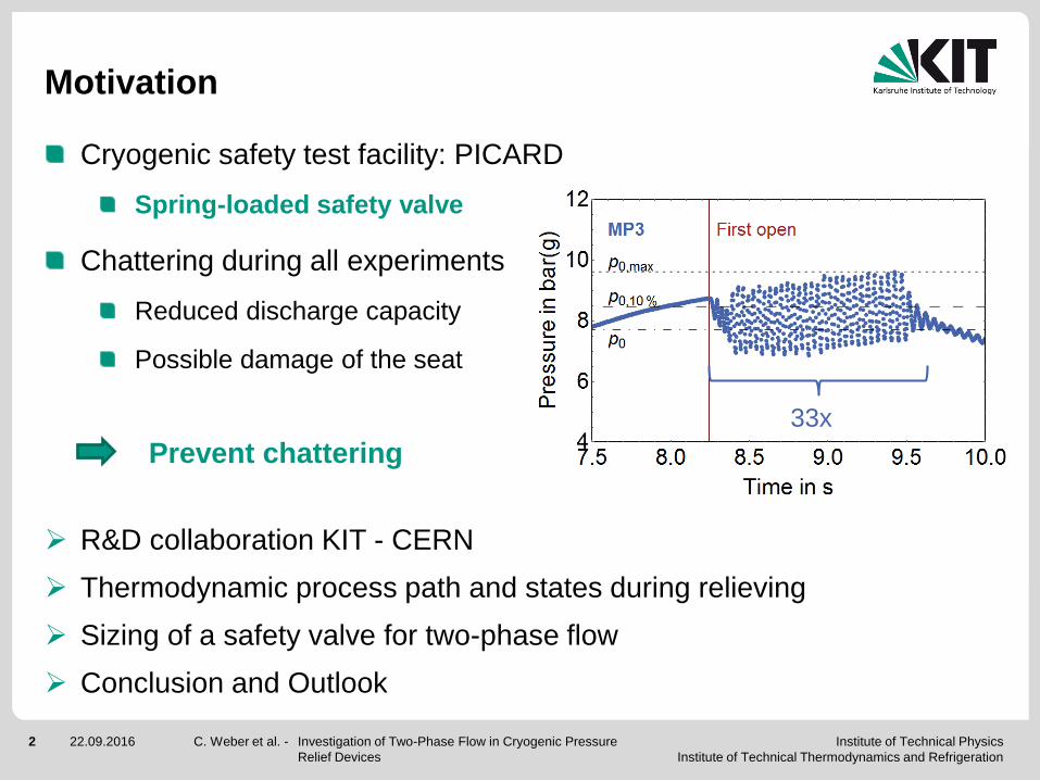
Motivation
C. Weber et al. - Investigation of Two-Phase Flow in Cryogenic Pressure
Relief Devices
Cryogenic safety test facility: PICARD
Spring-loaded safety valve
Chattering during all experiments
Reduced discharge capacity
Possible damage of the seat
Prevent chattering
R&D collaboration KIT - CERN
Thermodynamic process path and states during relieving
Sizing of a safety valve for two-phase flow
Conclusion and Outlook
33x

Institute of Technical Physics
Institute of Technical Thermodynamics and Refrigeration
3 22.09.2016
R&D COLLABORATION
C. Weber et al. - Investigation of Two-Phase Flow in Cryogenic Pressure Relief
Devices
Institute of Technical Physics
Institute of Technical Thermodynamics and Refrigeration
4 22.09.2016
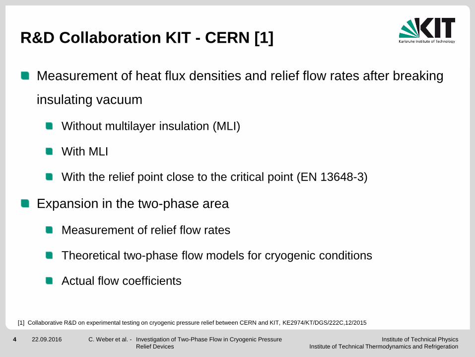
R&D Collaboration KIT - CERN [1]
C. Weber et al. - Investigation of Two-Phase Flow in Cryogenic Pressure
Relief Devices
Measurement of heat flux densities and relief flow rates after breaking
insulating vacuum
Without multilayer insulation (MLI)
With MLI
With the relief point close to the critical point (EN 13648-3)
Expansion in the two-phase area
Measurement of relief flow rates
Theoretical two-phase flow models for cryogenic conditions
Actual flow coefficients
[1] Collaborative R&D on experimental testing on cryogenic pressure relief between CERN and KIT, KE2974/KT/DGS/222C,12/2015

Institute of Technical Physics
Institute of Technical Thermodynamics and Refrigeration
5 22.09.2016
PROCESS PATH DURING
RELIEVING
C. Weber et al. - Investigation of Two-Phase Flow in Cryogenic Pressure Relief
Devices
Institute of Technical Physics
Institute of Technical Thermodynamics and Refrigeration
6 22.09.2016
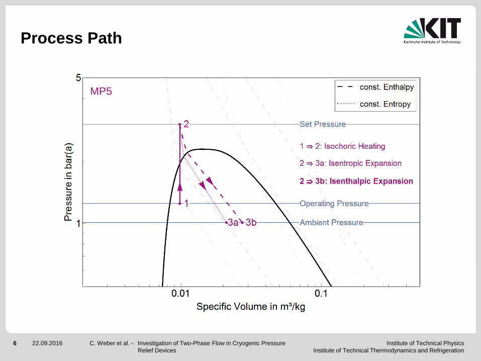
Process Path
C. Weber et al. - Investigation of Two-Phase Flow in Cryogenic Pressure
Relief Devices
MP5
Institute of Technical Physics
Institute of Technical Thermodynamics and Refrigeration
7 22.09.2016
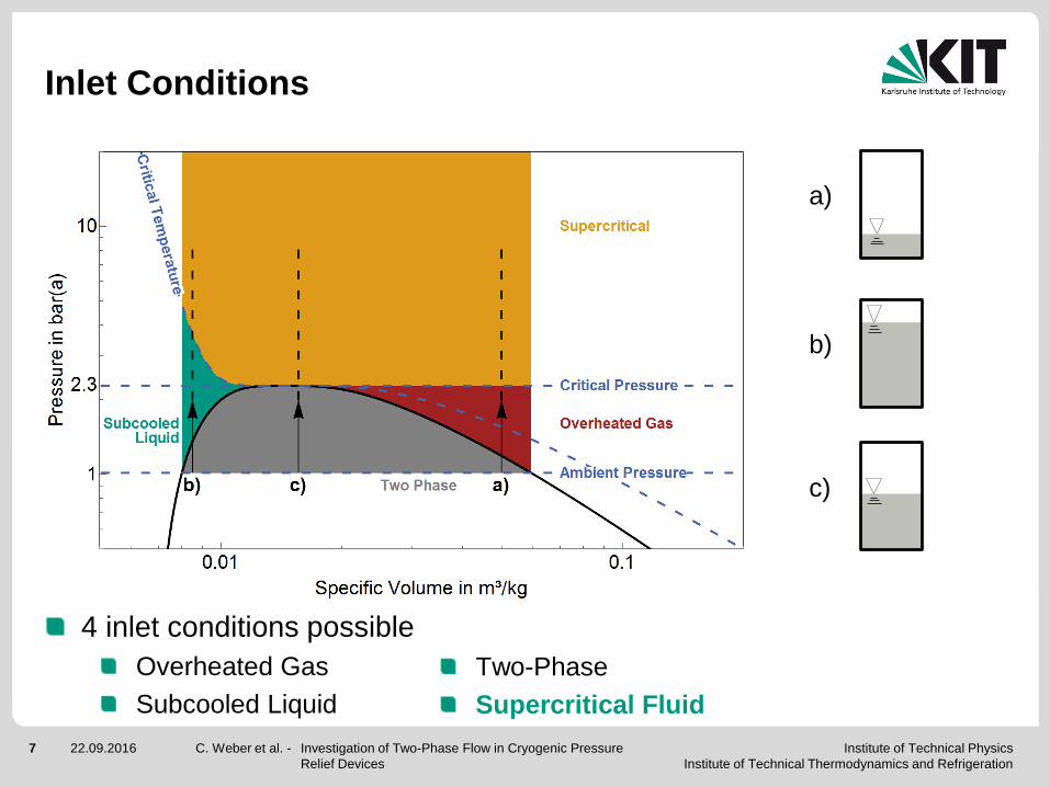
Inlet Conditions
C. Weber et al. - Investigation of Two-Phase Flow in Cryogenic Pressure
Relief Devices
Supercritical Fluid
4 inlet conditions possible
Overheated Gas
Subcooled Liquid
Two-Phase
a)
b)
c)
Institute of Technical Physics
Institute of Technical Thermodynamics and Refrigeration
8 22.09.2016
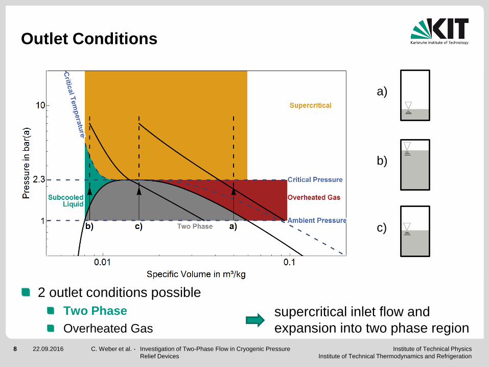
Two Phase
Outlet Conditions
C. Weber et al. - Investigation of Two-Phase Flow in Cryogenic Pressure
Relief Devices
2 outlet conditions possible
Overheated Gas
supercritical inlet flow and
expansion into two phase region
a)
b)
c)

Institute of Technical Physics
Institute of Technical Thermodynamics and Refrigeration
9 22.09.2016
SIZING FOR TWO-PHASE
FLOW
C. Weber et al. - Investigation of Two-Phase Flow in Cryogenic Pressure Relief
Devices
Institute of Technical Physics
Institute of Technical Thermodynamics and Refrigeration
10 22.09.2016
Sizing of Safety Valves
C. Weber et al. - Investigation of Two-Phase Flow in Cryogenic Pressure
Relief Devices
0dr
0id
.
2
pK
vmA
[1] ISO 4126-7, Safety devices for protection against excessive overpressure - Part 7 Common Data, 2013 [German Version].
[2] AD 2000-A2, Sicherheitseinrichtungen gegen Drucküberschreitung – Sicherheitsventile –.
[3] DIN EN 13648-3, Cryogenic vessels – Safety devices for protection against excessive pressure.
id
.
m
K dr
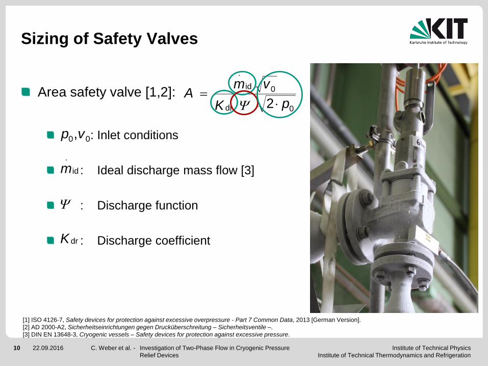
Area safety valve [1,2]:
: Inlet conditions
: Ideal discharge mass flow [3]
: Discharge function
: Discharge coefficient
00,vp
Institute of Technical Physics
Institute of Technical Thermodynamics and Refrigeration
11 22.09.2016
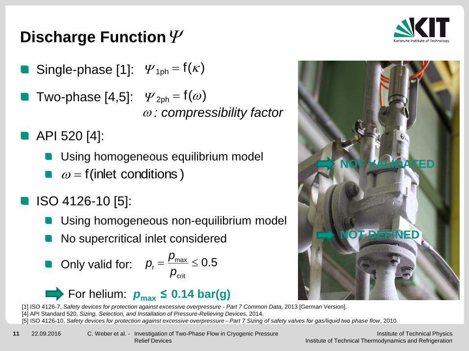
Discharge Function
Single-phase [1]:
Two-phase [4,5]:
: compressibility factor
API 520 [4]:
Using homogeneous equilibrium model
ISO 4126-10 [5]:
Using homogeneous non-equilibrium model
No supercritical inlet considered
Only valid for:
For helium: pmax ≤ 0.14 bar(g)
C. Weber et al. - Investigation of Two-Phase Flow in Cryogenic Pressure
Relief Devices
)(f1ph
)(f2ph
5.0crit
maxr
p
pp
[1] ISO 4126-7, Safety devices for protection against excessive overpressure - Part 7 Common Data, 2013 [German Version].
[4] API Standard 520, Sizing, Selection, and Installation of Pressure-Relieving Devices, 2014.
[5] ISO 4126-10, Safety devices for protection against excessive overpressure - Part 7 Sizing of safety valves for gas/liquid two phase flow, 2010.
NOT VALIDATED
NOT DEFINED
)conditions inlet(f
Institute of Technical Physics
Institute of Technical Thermodynamics and Refrigeration
12 22.09.2016
Sizing of Safety Valves
C. Weber et al. - Investigation of Two-Phase Flow in Cryogenic Pressure
Relief Devices
0dr
0id
.
2
pK
vmA
[1] ISO 4126-7, Safety devices for protection against excessive overpressure - Part 7 Common Data, 2013 [German Version].
[2] AD 2000-A2, Sicherheitseinrichtungen gegen Drucküberschreitung – Sicherheitsventile –.
[3] DIN EN 13648-3, Cryogenic vessels – Safety devices for protection against excessive pressure.
id
.
m
K dr
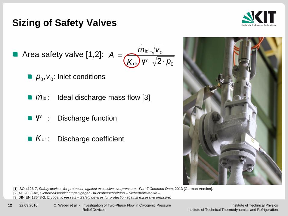
Area safety valve [1,2]:
: Inlet conditions
: Ideal discharge mass flow [3]
: Discharge function
: Discharge coefficient
00,vp
Institute of Technical Physics
Institute of Technical Thermodynamics and Refrigeration
13 22.09.2016
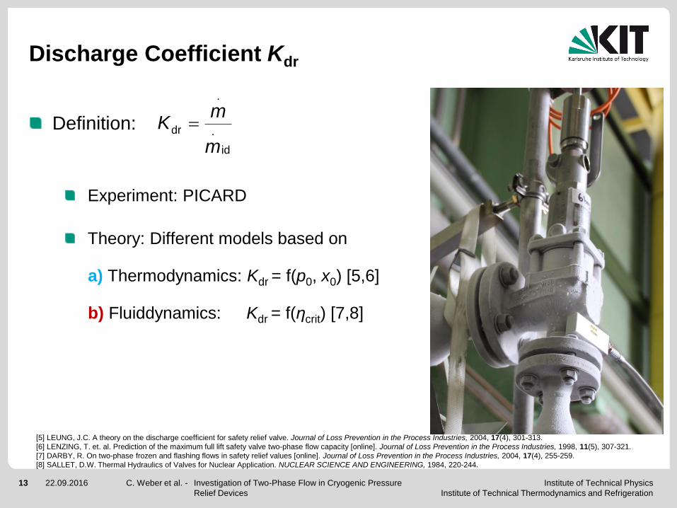
Discharge Coefficient Kdr
Definition:
Experiment: PICARD
Theory: Different models based on
a) Thermodynamics: Kdr = f(p0, x0) [5,6]
b) Fluiddynamics: Kdr = f(ηcrit) [7,8]
C. Weber et al. - Investigation of Two-Phase Flow in Cryogenic Pressure
Relief Devices
id
.
.
dr
m
mK
[5] LEUNG, J.C. A theory on the discharge coefficient for safety relief valve. Journal of Loss Prevention in the Process Industries, 2004, 17(4), 301-313.
[6] LENZING, T. et. al. Prediction of the maximum full lift safety valve two-phase flow capacity [online]. Journal of Loss Prevention in the Process Industries, 1998, 11(5), 307-321.
[7] DARBY, R. On two-phase frozen and flashing flows in safety relief values [online]. Journal of Loss Prevention in the Process Industries, 2004, 17(4), 255-259.
[8] SALLET, D.W. Thermal Hydraulics of Valves for Nuclear Application. NUCLEAR SCIENCE AND ENGINEERING, 1984, 220-244.
Institute of Technical Physics
Institute of Technical Thermodynamics and Refrigeration
14 22.09.2016
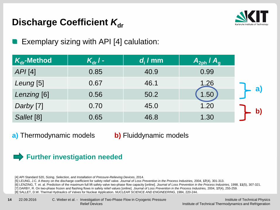
Kdr-Method Kdr / - di / mm A2ph / Ag
API [4] 0.85 40.9 0.99
Leung [5] 0.67 46.1 1.26
Lenzing [6] 0.56 50.2 1.50
Darby [7] 0.70 45.0 1.20
Sallet [8] 0.65 46.8 1.30
Discharge Coefficient Kdr
C. Weber et al. - Investigation of Two-Phase Flow in Cryogenic Pressure
Relief Devices
[4] API Standard 520, Sizing, Selection, and Installation of Pressure-Relieving Devices, 2014.
[5] LEUNG, J.C. A theory on the discharge coefficient for safety relief valve. Journal of Loss Prevention in the Process Industries, 2004, 17(4), 301-313.
[6] LENZING, T. et. al. Prediction of the maximum full lift safety valve two-phase flow capacity [online]. Journal of Loss Prevention in the Process Industries, 1998, 11(5), 307-321.
[7] DARBY, R. On two-phase frozen and flashing flows in safety relief values [online]. Journal of Loss Prevention in the Process Industries, 2004, 17(4), 255-259.
[8] SALLET, D.W. Thermal Hydraulics of Valves for Nuclear Application. NUCLEAR SCIENCE AND ENGINEERING, 1984, 220-244.
a)
b)
a) Thermodynamic models b) Fluiddynamic models
Further investigation needed
Exemplary sizing with API [4] calulation:

Institute of Technical Physics
Institute of Technical Thermodynamics and Refrigeration
15 22.09.2016
CONCLUSION & OUTLOOK
C. Weber et al. - Investigation of Two-Phase Flow in Cryogenic Pressure Relief
Devices
Institute of Technical Physics
Institute of Technical Thermodynamics and Refrigeration
16 22.09.2016
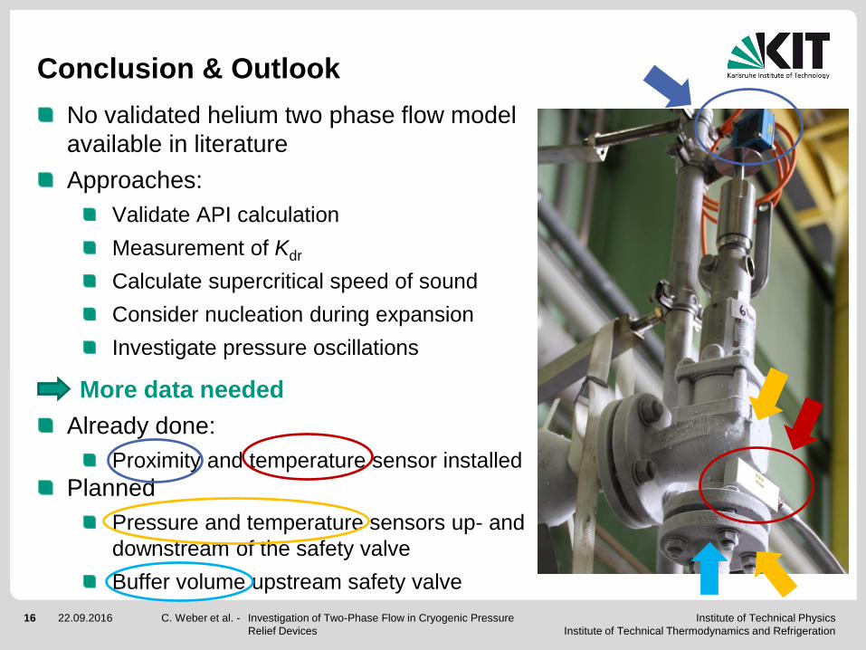
Conclusion & Outlook
No validated helium two phase flow model
available in literature
Approaches:
Validate API calculation
Measurement of Kdr
Calculate supercritical speed of sound
Consider nucleation during expansion
Investigate pressure oscillations
More data needed
Already done:
Proximity and temperature sensor installed
Planned
Pressure and temperature sensors up- and
downstream of the safety valve
Buffer volume upstream safety valve
C. Weber et al. - Investigation of Two-Phase Flow in Cryogenic Pressure
Relief Devices
Institute of Technical Physics
Institute of Technical Thermodynamics and Refrigeration
17 22.09.2016
Thank you for your attention.
C. Weber et al. - Investigation of Two-Phase Flow in Cryogenic Pressure
Relief Devices

![Two Phase Flow Systems. - Aquatherm · Since a Waterfall Flow reduces the flow and a Two Phase Flow creates a lower rate [l/s] than originally calculated, based on a single-phase](https://img.pdfslide.us/doc/110x75/5d67411288c993b2178b622a/two-phase-flow-systems-since-a-waterfall-flow-reduces-the-flow-and-a-two.jpg)