Embed Size (px)
Citation preview
INVESTIGATION OF THERAPY IMPROVEMENT USING
REAL-TIME PHOTOACOUSTIC IMAGING GUIDED
HIGH INTENSITY FOCUSED ULTRASOUND
By
HUIZHONG CUI
Submitted to the graduate degree program in Bioengineering Program and the Graduate
Faculty of the University of Kansas in partial fulfillment of the requirements for the
degree of Doctor of Philosophy.
________________________________
Chairperson Dr. Xinmai Yang
________________________________
Dr. Larry Cook
________________________________
Dr. M. Laird Forrest
________________________________
Dr. Carl W. Luchies
________________________________
Dr. Mihai Popescu
Date Defended: 09/26/2012

ii
The Dissertation Committee for Huizhong Cui
certifies that this is the approved version of the following dissertation:
INVESTIGATION OF THERAPY IMPROVEMENT USING
REAL-TIME PHOTOACOUSTIC IMAGING GUIDED
HIGH INTENSITY FOCUSED ULTRASOUND
________________________________
Chairperson Dr. Xinmai Yang
Date Approved: 09/26/2012

iii
Abstract
There are a lot of risks in cancer treatment by invasive surgery, such as bleeding,
wound infection, and long recovery time, etc. Therefore, there is great need for
minimally- or non-invasive treatment. High intensity focused ultrasound (HIFU) is a
rapidly growing and truly non-invasive technology. It has been widely used in therapeutic
applications, such as rapid tissue heating and tissue ablation. With proper imaging
guidance, HIFU treatment can be performed totally noninvasively. Currently, ultrasound
imaging-guided HIFU has been extensively studied. However, ultrasound imaging
guidance is less precise because of the relatively low imaging contrast, sensitivity, and
specificity for noninvasive detection. In this study, we employed photoacoustic imaging
(PAI) technique, which has been developed a novel promising imaging technique for
early cancer detection, to guide HIFU treatment. The goal of this study is to investigate
the feasibility of PAI to guide, monitor in real time and enhance the HIFU therapy.
In this dissertation, as the first step, the integrated PAI and HIFU system had been
shown to have the feasibility to guide HIFU both ex vivo and in vivo. Then, the system
was improved and developed to a real-time PAI-guided HIFU system. It is demonstrated
that the sensitivity of PA detection for HIFU lesion is very high and the saturation of PA
signals can be used as the indicator for tissue coagulation. During the temperature
measurement using this system, laser-enhanced HIFU heating was found. Thus, we
further investigated the laser enhanced technique in both HIFU heating and pulsed HIFU
thrombolysis. In the HIFU therapy, laser light was employed to illuminate the sample
concurrently with HIFU radiation. The resulting cavitation was detected with a passive

iv
cavitation detector. We demonstrated that concurrent light illumination during HIFU has
the potential to significantly enhance HIFU by reducing cavitation threshold.
v
Acknowledgements
I would like to express my sincerely thanks to all those who gave me the
possibility to complete this dissertation.
First, I wish to express my deepest gratitude to my advisor, Dr. Xinmai Yang, for
his excellent and patient guidance throughout my four years graduate study and research.
When I just arrived at the University of Kansas and struggled with integrating into a
foreign country and lack of necessary expertise, Dr. Yang's support and encouragement
gave me the strength to continue and help me make achievement today. I will never
forget his words which he told me more than once to encourage me to independently
think about the research I was doing but not to be satisfied as an experimentalist or
technician. Dr. Yang and his family are going through a tough time recently, I want to
give my best wishes to him and his family and hopefully everything will get better soon.
I would like to thank my committee members: Dr. Larry Cook, Dr. M. Laird
Forrest, Dr. Carl W. Luchies and Dr. Mihai Popescu. Their comments and suggestions in
my proposal defense are critical and constructive. I would never finish my dissertation
without their guidance. A special thank is given to Dr. Paulette Spencer, who is the
director of BioEngineering Research Center (BERC) and provides us with an excellent
atmosphere for doing research.
I would like to thank Janggun Jo, Jacob Staley and Behrouz Soroushian, who are
my current and former co-workers and also good friends. They were always willing to
help and give their best suggestions. Many thanks to Dr.Anil Misra, Dr. Charles Ye, Dr.

vi
Shiping Huang, Rananathan Parthasarathy, Viraj Singh and other colleagues in BERC. It
would have been a lonely lab without them.
I would also like to thank my parents, grandparents, uncle and parents-in-law who
always support and encourage me with their best wishes unreservedly.
Finally, I would like to thank my wife Ti Zhang for her unwavering love,
considerate care and companionship. I am so blissful to share these wonderful four years
with her, no matter good times or bad.

vii
Table of Contents
Abstract ........................................................................................... iii
Acknowledgements ........................................................................... v
List of Tables ....................................................................................xi
List of Figures ................................................................................ xii
Chapter 1 Introduction ..................................................................... 1
1.1 Background and motivation .................................................................. 1
1.2 The goal of this research ....................................................................... 4
Chapter 2 The integration of photoacoustic imaging and high
intensity focused ultrasound ..................................................... 5
2.1 Introduction .......................................................................................... 5
2.2 Materials and Methods .......................................................................... 8
2.3 Results ................................................................................................ 11
2.4 Discussion and Conclusions ................................................................ 15
viii
Chapter 3 In-vivo imaging and treatment of solid tumor using
integrated photoacoustic imaging and high intensity focused
ultrasound system .................................................................... 17
3.1 Introduction ........................................................................................ 17
3.2 Materials and methods ........................................................................ 18
3.2.1 Integrated PAI/HIFU system ................................................... 18
3.2.2 In vitro test for imaging resolution and depth ........................... 21
3.2.3 In vitro test for gold nanorods .................................................. 23
3.2.4 Animal preparation and experiment procedure ......................... 24
3.3 Results and Discussion........................................................................ 25
3.4 Conclusion .......................................................................................... 28
Chapter 4 Real-time monitoring of high-intensity focused ultrasound
ablations with photoacoustic technique: an in vitro study .... 29
4.1 Introduction ........................................................................................ 29
4.2 Materials and methods ........................................................................ 32
4.3 Results and Discussion........................................................................ 34
4.4 Conclusion .......................................................................................... 39

ix
Chapter 5 Enhanced-heating effect during photoacoustic imaging-
guided high-intensity focused ultrasound .............................. 40
Chapter 6 Laser-enhanced cavitation during high intensity focused
ultrasound: an in vivo study ................................................... 48
6.1 Introduction ........................................................................................ 48
6.2 Materials and Methods ........................................................................ 49
6.2.1 Experimental system ............................................................... 49
6.2.2 In vivo experiment .................................................................. 51
6.3 Results ................................................................................................ 53
6.4 Discussion and conclusions ................................................................. 55
Chapter 7 Laser enhanced high-intensity focused ultrasound
thrombolysis: an in vitro study ............................................... 57
7.1 Introduction ........................................................................................ 57
7.2 Materials and Methods ........................................................................ 59
7.2.1 Experimental system ............................................................... 59
7.2.2 Clot preparation ....................................................................... 60
7.2.3 Experiment procedure ............................................................. 61
7.2.4 Assessment of ultrasound and laser parameters ........................ 61

x
7.3 Results and Discussion........................................................................ 62
7.4 Conclusion .......................................................................................... 65
Chapter 8 Conclusion ..................................................................... 67
8.1 Summary ............................................................................................ 67
8.2 Findings .............................................................................................. 67
8.3 Suggestions for future work ................................................................ 69
Bibliography .................................................................................... 71

xi
List of Tables
Table 5.1 Number of HIFU lesions with cavitation from five HIFU sonications at
each HIFU intensity level with laser on and off. ............................ 46

xii
List of Figures
Figure 2.1 Schematic of the integrated PAI and HIFU system.............................. 8
Figure 2.2 The cross-section of a human hair in water. ...................................... 10
Figure 2.3 (a) Photoacoustic image of a chicken liver after HIFU ablation. The
ultrasound intensity at the focal zone is 104 W/cm2, the ablation duration
is 1 s at each scanning position. (b) Photograph of the chicken liver
after HIFU ablation. The HIFU targeted area is outlined on (a). .... 13
Figure 2.4 Photoacoustic images of a piece of swine liver embedded in the chicken
breast (a) before the HIFU ablation and (b) after HIFU ablation. The
ultrasound intensity at the focal zone is 103 W/cm2, and the ablation
duration is 4 s. (c) and (d) are photographs of the swine liver before and
after HIFU ablation, respectively. .................................................. 14
Figure 3.1 Schematic of the integrated PAI and HIFU system............................ 20
Figure 3.2 (a) B-scan image of a human hair in water. (b) Signal profile at the vertical
dashed line position in (a). (c) Signal profile at the horizontal dashed line
position in (a). ............................................................................... 21
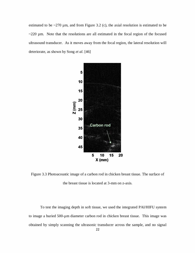
Figure 3.3 Photoacoustic image of a carbon rod in chicken breast tissue. The surface
of the breast tissue is located at 3-mm on z-axis ............................ 22
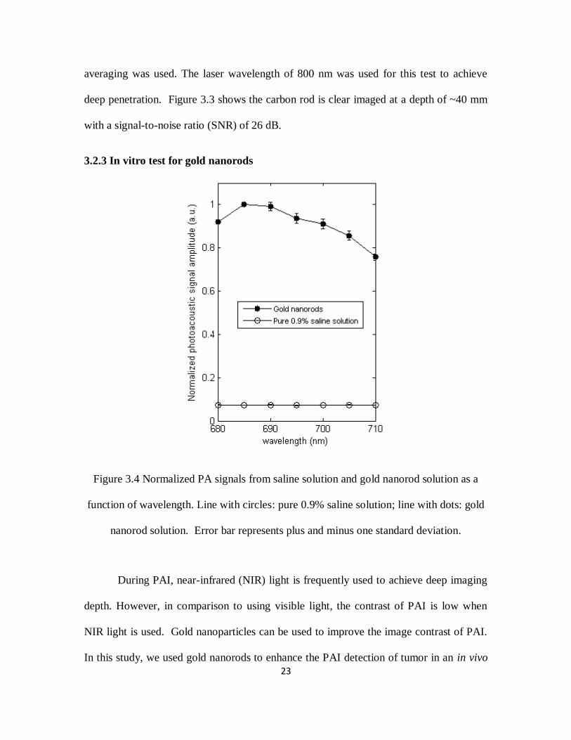
Figure 3.4 Normalized PA signals from saline solution and gold nanorod solution as a
function of wavelength. Line with circles: pure 0.9% saline solution; line
with dots: gold nanorod solution. Error bar represents plus and minus
one standard deviation. .................................................................. 23

xiii
Figure 3.5 Noninvasive MAP images taken before gold nanorod injection (a), after
nanorod injection (b), and after HIFU ablation (c). All PA images are
normalized by the maximum intensity of all three images, and are shown
at the same intensity grayscale ...................................................... 26
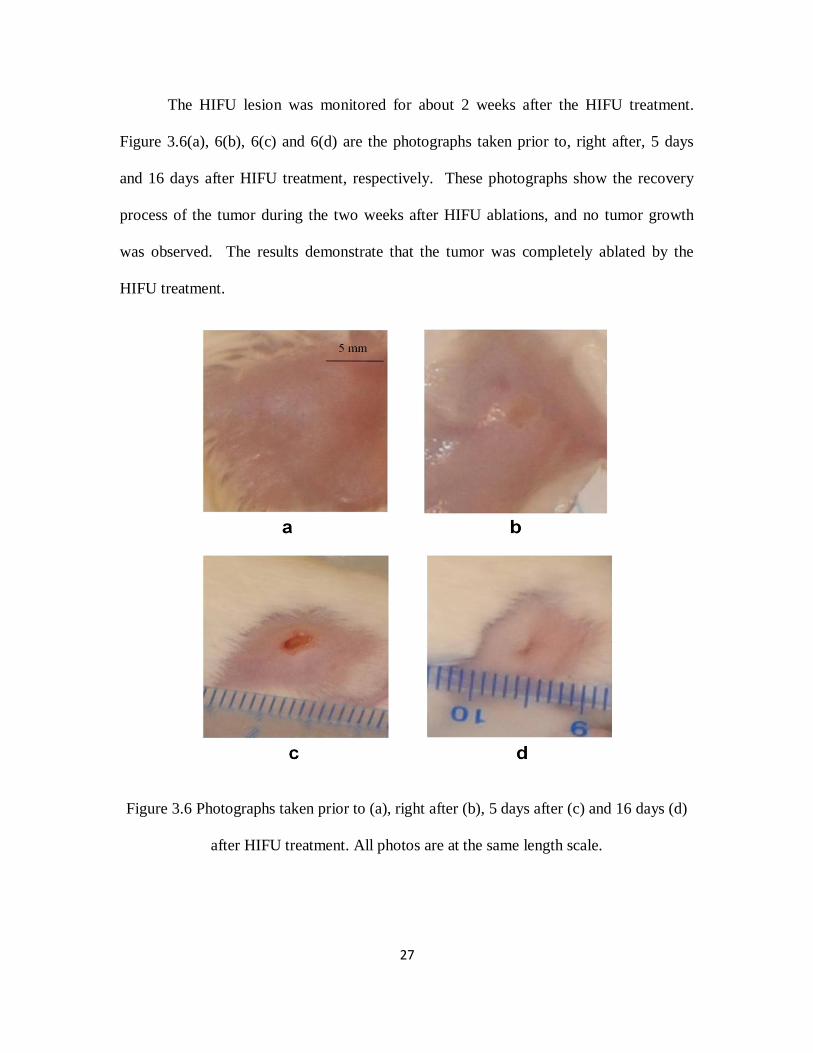
Figure 3.6 Photographs taken prior to (a), right after (b), 5 days after (c) and 16 days
(d) after HIFU treatment. All photos are at the same length scale. . 27
Figure 4.1 Diagram of experimental setup. ........................................................ 32
Figure 4.2 Time sequence of data acquisition and HIFU waves. ........................ 34
Figure 4.3 Results from five separated experiments with an intensity of 1000W/cm2,
14s duration. (a), (b) the averaged PA amplitude and temperature with
standard error of the mean (SEM), respectively, (c) the relation between
the PA amplitude and the calculated thermal dose from the averaged
temperature, and (d) photographs of beef kidney after HIFU treatment.
..................................................................................................... 35
Figure 4.4 PA amplitude as the function of temperature and the linear fit. The
coefficient of determination R2=0.8727. ........................................ 37
Figure 4.5 (a) PA amplitudes from a beef kidney sample placed in a 50˚C temperature
water bath; (b) the relation between the PA amplitude and the calculated
thermal dose. ................................................................................. 38
Figure 5.1 System schematic. ............................................................................ 41

xiv
Figure 5.2 Temperature enhancement during PAI-guided HIFU. Lines with stars and
circles represent the temperature measured by a T-type thermocouple
during HIFU exposure when PAI system was on and off, respectively.
..................................................................................................... 43
Figure 5.3 Photograph of HIFU lesions inside a tissue sample after HIFU exposure.
..................................................................................................... 44
Figure 6.1 System schematic. ............................................................................ 50
Figure 6.2 In vivo measurements of cavitation pressure threshold. The mean acoustic
cavitation thresholds from five measurements were plotted as a function
of laser fluence at the sample surface. Error bars are the standard
deviations of five measurements.(a) 760 nm laser wavelength, 5 mm
treatment depth, 2s HIFU duration time. (b) 760 nm laser wavelength,
10 mm treatment depth, 2s HIFU duration time. (c) 960 nm laser
wavelength, 10 mm treatment depth, 2s HIFU duration time.(d) 760 nm
laser wavelength, 10 mm treatment depth, 4s HIFU duration time. 54
Figure 7.1 System schematic. ............................................................................ 59
Figure 7.2 Thrombolysis efficiency correlated with HIFU wave pulse length in the
treatment with and without laser radiation. .................................... 62
Figure 7.3 Thrombolysis efficiency measured under different HIFU pressures with
and without laser radiation. ........................................................... 63
Figure 7.4 Thrombolysis efficiency with increasing laser fluence. ..................... 64

1
Chapter 1 Introduction
1.1 Background and motivation
High intensity focused ultrasound (HIFU) has been served as a truly non-invasive
tool to treat solid tumors[1-9]. During HIFU, high intensity ultrasound is delivered and
deposits a certain amount of energy to a target. The induced rapid local temperature rise,
which is called hyperthermia or thermal ablation, leads to the irreversible tissue
coagulation and cell death. Since HIFU technique was first introduced by Lynn et al.[10]
in 1942, it has been performed in a growing number of clinical studies on several benign
and malignant tumors (prostate, breast, uterine, liver, kidney, pancreas, bone, and
brain)[9, 11-22].
In the last decade, HIFU have made remarkable achievements in the clinical
studies with the advent of modern imaging modalities such as ultrasound (US) imaging
and magnetic resonance imaging (MRI), which can provide accurate therapy guidance.
Currently, more than 90% of HIFU is performed with ultrasound guidance.
Although ultrasound imaging is inexpensive and can be performed in real time, it has
relatively low imaging contrast, sensitivity, and specificity for noninvasive detection[23-
25], which cause loss of guidance accuracy. In addition, temperature rise during HIFU
cannot yet be accurately measured with ultrasound, although efforts have been made[26-
30]. Magnetic resonance imaging (MRI) is a more viable imaging technique to guide
HIFU therapy because it can produce temperature images[31-36]. However, MRI makes
the treatment expensive and slow. In addition, the patient must remain still in a magnet

2
bore, which may be a problem for claustrophobic patients. In some MRI modes (such as
head and neck imaging), special RF coils are used to fit closely to the patient’s anatomy,
and these coils will interfere with HIFU transducer placement.
Photoacoustic imaging, also called optoacoustic imaging or thermoacoustic
imaging, has been developed as a novel promising imaging technique for early cancer
detection[37-44]. It is a hybrid technique that can image the distribution of optical
absorption deep inside the tissue based on the photoacoustic effect. When short-pulsed
laser beams irradiate on the biological tissues, the ultrasonic waves are generated due to
pressure rise through transient thermoelastic expansion. The ultrasonic waves, referred as
photoacoustic waves, can be detected by an ultrasonic transducer and then converted to
electrical signal that can be collected by PC to analyze or form PA images. PAI
overcomes the limitations of ultrasound imaging modalities and combines optical contrast
with ultrasonic resolution. PAI has demonstrated imaging depth more than 5 cm[45] with
the imaging resolution (from 2 µm to 500 µm) scalable to the imaging depth[42, 46].
Additionally, PAI has the advantages of being inexpensive and portable. It is
demonstrated that PAI has the capability to provide guidance for HIFU treatment on solid
tumors and monitor thermal lesions generated by HIFU or other means[47-50].
While HIFU therapy technique with proper imaging modalities is developing
rapidly, its application is also expanding, e.g. large tumor treatment. It requires larger
amount of energy deposited in the tumor region, which can be fulfilled by enhancing the
local ultrasound absorption and ultrasound intensity. Increasing the HIFU intensity is one
of the simple solutions. However, high power output will induce serve skin burns and

3
also present a great challenge for the design of HIFU system, including the design of
transducer and the electronic circuits. An alternative way to avoid very high ultrasound
intensity in large tumor treatment is to increase the local ultrasound absorption so that
more ultrasound energy can be deposited in the local region at a relatively low HIFU
intensity level. As a result, enhanced HIFU heating would be achieved at a relatively low
HIFU intensity level, and side effects such as skin burns would be avoided. To enhance
HIFU heating, acoustic cavitation has been investigated[51, 52] to have the capacity to
increase the local ultrasound absorption and thus enhance heating.
The use of pulsed HIFU to potentiate thrombolysis is another important
application of HIFU. Catheter-based ultrasound has been extensively studied as an
efficient method to treat deep venous thrombosis (DVT) clinically[53-59]. During the
treatment, the catheter is placed inside the blood clot and dissolves the clot through
oscillating wires at high frequency and high intensity. However, catheter-based
ultrasound is an invasive way to treat thrombus. The non-invasive methods are necessary
to avoid bleeding, wound infection, and long recovery time. Therefore, HIFU technique
has the potential for thrombolysis treatment. When using HIFU to dissolve the blood clot,
the clot disruption are mainly due to cavitation effect[54, 57, 60-62]. However, using
pulsed HIFU treatment alone are limited and have a relatively low thrombolysis
efficiency[63, 64].
As we mentioned, in HIFU applications, acoustic cavitation plays a vital role in
both HIFU ablation and pulsed HIFU thrombolysis. When cavitation occurs, collapse
(stable cavitation) and pulsate violently (inertial cavitation) can damage nearby structures

4
without heating complex overlying layers. However, cavitation thresholds are widely
varying in tissues and cavitation requires high intensities to initiate. Either
microbubbles[65-67] or nanoparticle have been studied as a method of delivering nuclei
into the target region[52]. The addition of intravenously injected microbubbles can
enhance the effects of ultrasound and lower the energy requirement for producing heating
effect through decreasing the cavitation threshold.[57, 62, 68, 69] In addition,
microbubbles and thrombolytic drug can be combined together with HIFU therapy for
targeted drug delivery, drug transport acceleration[70-77] and eventually enhancing
HIFU. However, the use of microbubbles and nanoparticle, however, requires the
systematic injection of foreign particles into the blood stream, and would have a lot
concerns regarding the toxicity, efficiency, etc[78].
1.2 The goal of this research
In this study, we will first demonstrate that the integrated PAI and HIFU system
can be used to provide excellent guidance for HIFU treatment in both ex vivo and in vivo
experiments. Secondly, the integrated system will be modified to monitor HIFU
treatment in real time. Finally, we will develop and evaluate a new system based on the
integrated system for laser-enhanced particle-free HIFU heating. During the experiment,
the laser light will be employed to treat the target area concurrently with HIFU treatment
to help induce cavitation, which is the key factor for both HIFU heating and thrombolysis
treatment. The finding, for the first time, will potentially allow us to enhance HIFU
therapy at a relatively low HIFU intensity level without introducing foreign particles in to
the targeted tissue region.

5
Chapter 2 The integration of photoacoustic imaging and high intensity
focused ultrasound
2.1 Introduction
High intensity focused ultrasound (HIFU) has been used as an effective non-
invasive method to treat solid tumors deep in the body. During a HIFU treatment, the
high intensity ultrasound is delivered to the focal region of the HIFU transducer, and
subsequently absorbed by the soft tissue in the focal region. The absorption of HIFU
energy induces a rapid temperature rise, which results in tissue coagulation, and finally
leads to the irreversible tumor cell death and severe damage to tumor blood vessels in the
treated region. [8, 79] The soft tissue outside the focal region will be undamaged because
the ultrasound intensity is relative low in those regions.
To improve the effectiveness of HIFU treatment, we need to locate and monitor
the treated tissue so that the guidance and feedback on the treatment can be provided.[80]
Current imaging modalities such as magnetic resonance imaging (MRI) and ultrasound
imaging have been used to visualize the treatment process and monitor the immediate
thermal effects.[9, 22, 32, 81, 82] However, MRI makes the treatment cumbersome and
expensive. Although ultrasound imaging is inexpensive and can potentially perform with
the same HIFU transducer in real time, it has relatively low imaging contrast, sensitivity,
and specificity for noninvasive detection.
Photoacoustic imaging (PAI), also called optoacoustic imaging or thermal
acoustic imaging, has been developed as a novel promising imaging technique for early

6
cancer detection.[37, 39-41, 43, 83] PAI is based on the generation of photoacoustic
waves by safely depositing short-pulsed optical energy into tissue. Each laser pulse
causes a rapid temperature rise on the order of 10 millidegrees. The ultrasonic waves
generated due to thermoelastic expansion can be detected with either a single-element
ultrasonic transducer or an array of ultrasonic transducers and then used to reconstruct an
image.[83] PAI technology is designed to overcome the poor spatial resolution of purely
optical imaging yet to retain the high optical contrast in the deep region beyond the depth
limit, which is ~1 mm, for high-resolution optical imaging, and demonstrated the
capability of providing images with optical contrast and ultrasound resolution in regions
up to 5 cm deep in soft tissue.[45]
PAI has demonstrated to be capable of monitoring thermal lesions generated by
HIFU or other means.[49, 50] A study for PAI guidance of HIFU has also been proposed
with the application of time-reversal technique.[84] Currently, PAI and HIFU are
performed by two separate systems. When PAI and HIFU are performed separately by
two systems, a tissue imaging window for PAI, which utilize both light and ultrasound,
and a therapeutic window for HIFU to deliver ultrasound energy will be required. In
clinic practice, two tissue windows are sometimes difficult to be identified. In addition,
when two separate systems are used, the location of the two systems needs to be known
precisely so that the treatment will be performed on the lesion, which is identified on the
image. To align the treatment area with the imaging area could be a challenge and may
result in the ablation of normal tissue.

7
One way to improve PAI-guided HIFU is to use an integrated system for PAI and
HIFU. The combination of PAI and HIFU is technically possible. In PAI technology,
both laser and ultrasound energy are involved in the imaging process. The ultrasonic
transducer’s sole purpose within the modality is to act as a receiver of the acoustic signals.
If the ultrasonic transducer is used as a transmitter to deliver high ultrasound energy to
soft tissue, the PAI system potentially has therapeutic applications as a HIFU system.
HIFU can treat soft tissues up to 10 cm, whereas the deep reflection-mode PAI,
when a 5-MHz ultrasonic transducer is used, can provide penetration depth up to ~3.8 cm
without using any contrast agents.[85] With the aid of PAI contrast agents, the deep
reflection-mode PAI should be able to image even deeper. Therefore, a reflection-mode
PAI-guided HIFU may be used to treat breast tumor, prostate tumor, and tumors in the
lymphatic system, etc..
In this paper, we investigated the feasibility of using an integrated PAI and HIFU
system to non-invasively detect the location of the target tissue sample and then plan and
perform the HIFU ablation on the target tissue sample. The biggest advantage of a
combined reflection-mode PAI and HIFU with one transducer lies on the fact that only
one tissue imaging/therapy window is required with this technique, and therefore, it will
be much friendly to be used in future clinic practice. Furthermore, with the combined
system, the treatment can be performed precisely on the area identified through the
obtained image, and therefore, the treatment location can be very precise. This advantage
may be of more interest when treating small lesions, which may be identified in early
cancer detections.

8
In the combined PAI/HIFU system, we utilize a reflection-mode PAI (also called
PAM)[85, 86] with a standard 5-MHz HIFU transducer as our photoacoustic signal
detector. The HIFU transducer also delivers high intensity ultrasound energy to soft
tissue during tissue ablations. Our results show that the combined PAI/HIFU is capable of
performing imaging and therapy.
2.2 Materials and Methods
Figure 2.1 Schematic of the integrated PAI and HIFU system
Figure 2.1 shows the schematic of the integrated PAI and HIFU system. During
PAI mode, a tunable OPO laser (Surelite OPO PLUS; Continuum), pumped by a Q-
switched Nd:YAG laser (Surelite III; Continuum) is used to generate laser light. The
system operates at 680 nm wavelength with a 10 Hz pulse repetition rate for excitation of
the tissue. The produced laser light is directed to a conical lens via a group of prisms,

9
which enable higher optical energy delivery[85] than the optical fibers-based PAI
systems.[86] The laser passing through the conical lens forms a ring-shaped illumination.
The ring-shaped light is transmitted to an optical condenser and refocused inside the
tissue sample. At the tissue surface, the ring has a diameter of ~5 mm, which has the
advantage of reducing the generation of surface photoacoustic signals, and allowing for
the improvement in the detection of deep photoacoustic signals.[85, 86] The
subsequently generated photoacoustic signals are detected by a 5-MHz focused ultrasonic
transducer (SU-108-013, Sonic Concepts), which has a focal length of 35 mm and
diameter of 33 mm. The transducer delivers the recorded acoustic signal to a pre-
amplifier (5072PR, Olympus-NDT). After signal amplification, the detected
photoacoustic signals are collected by a PC through a digital oscilloscope (Tektronix
DPO 3034). The transducer is mounted in the middle of the condenser lens and driven by
a XYZ-linear translation stage for raster scanning on the tissue sample. Two prisms are
used to enable the beam-folding for the 2D scan. Prism Y can only move on the Y
direction, whereas prism XY can move on both X and Y direction. This design for PAI
has been presented by Song et al.[85] for deep PAI, and proved to generate good-
resolution photoacoustic images in deep regions inside soft tissue.
During HIFU mode, the 5-MHz focused ultrasonic transducer was used as a
transmitter. At each scanning position, a continuous ultrasonic wave, which was
generated by a function generator (HP33250A; Agilent Technologies) and amplified by a
50 dB RF amplifier (350L; ENI Technology, Inc), was sent to the transducer. The
transducer, which was driven by PC-controlled motors, induced the HIFU field step by
step in the tissue sample.

10
In order to quantify the actual resolution of our PAI system with the HIFU
transducer as a receiver, a well-controlled sample (human hair, ~50 µm in diameter) in
water was imaged. Figure 2.2 shows the cross-section of the human hair on a B-mode
scan image. We can achieve a lateral resolution of ~270 µm and an axial resolution of
~200 µm.
Figure 2.2 The cross-section of a human hair in water.
To test the ability of the system in the detection of optical contrast change before
and after HIFU, we performed in vitro test in a chicken liver. A slice (2 mm thick) of

11
chicken liver was imaged first, and then HIFU was used to sonicated a portion of the liver.
After HIFU sonication, PAI was used to image the liver slice again.
To further simulate the tumor detections by PAI and localized ablation by HIFU,
we embedded a thin slice of swine liver tissue (2-mm thick) between two fresh chicken
breast tissues slabs. The thicknesses of the two chicken breast slabs were different. The
upper slab was ~1-mm thick, while the lower slab was approximately 10-mm thick and
much larger than the upper slab in order to reduce the interference from signals generated
at the bottom of the sample. The samples were immersed in water, and air bubbles were
carefully removed before PAI. Since the optical absorption in the swine liver tissue is
much higher than that in the chicken breast tissue, good image contrast should be
achieved between them. During the experiments, PAI was first used to detect the
location of the swine liver, and then, HIFU ablation was performed based on the exact
position of the swine liver sample identified on the photoacoustic image. After HIFU
ablation, PAI was performed again to detect the change on the generated photoacoustic
signals.
For the photoacoustic image formation, we take maximum-amplitude-projected
(MAP) image. On a MAP image, the maximum value of the photoacoustic signal
detected at each scan position is plotted.
2.3 Results
Figure 2.3 (a) shows the photoacoustic image of the chicken liver after a portion
of the liver went through the HIFU ablation, whereas figure 3 (b) shows the photograph
of the chicken liver. Compared with other untreated region, the HIFU treated region

12
shows a great enhancement in the amplitude of photoacoustic signals. On the image, the
averaged contrast ratio between the treated and untreated region is about 3.6, with a
standard deviation of 1.8. The increase in the amplitude of photoacoustic signals after
HIFU treatment is consistent with previous results[49, 50]. The increase in the amplitude
of photoacoustic signals after HIFU can be caused by a combination of several factors.
Notably, the Grüneisen parameter is affected by tissue coagulation.[87] The intensity at
the focal region was estimated to be 104
W/cm2 during the HIFU ablation, and the
treatment duration was 1 s.
Photoacoustic images of the swine liver tissue in chicken breast tissues before and
after HIFU are presented in Figure 2.4. Figure 2.4(a) was taken before HIFU ablation on
the swine liver sample and it shows the location of liver tissue and shape, which acted as
the guidance for the subsequent HIFU ablation. For HIFU ablation, we chose the
scanning area of 5.4 mm×7 mm which accurately cover the entire area of the liver and
avoid burning the surrounding tissue. The step size of the scanning on the sample was
0.2 mm. At each scanning position, the ultrasonic wave was focused into the sample for
4 s, with a focal intensity of 103
W/cm2. Compared with Figure 2.4(a), Figure 2.4(b),
which is the photoacoustic image after HIFU ablation, reveals the swine liver tissue with
approximately the same size and slight increase at PAI contrast, which is shown by the
increased photoacoustic signal amplitudes in the MAP image. Figure 2.4(c) and (d)
shows the photograph of the liver tissue before and after HIFU ablation.
To quantify the change in the photoacoustic image after HIFU, we calculated
averaged enhancement in the amplitude of photoacoustic signals before and after HIFU in

13
the HIFU treated region. The average enhancement is ~6 % with a standard deviation of
4%. The enhancement in photoacoustic signals is small because the ultrasound intensity
at the focal region was only 103 W/cm
2, and the treatment duration was 4 s for current
HIFU ablation. We anticipate that a higher enhancement in photoacoustic signal should
be achieved if a higher ultrasound intensity level at the focal region is used during HIFU
ablation, as shown in Figure 2.3.
Figure 2.3 (a) Photoacoustic image of a chicken liver after HIFU ablation. The
ultrasound intensity at the focal zone is 104 W/cm2, the ablation duration is 1 s at each
scanning position. (b) Photograph of the chicken liver after HIFU ablation. The HIFU
targeted area is outlined on (a).

14
The results in Figure 2.4 demonstrate that the combined PAI/HIFU system with
one transducer is capable of perform PAI-guided HIFU ablation. PAI can be performed
to identify the location of the targeted region, and HIFU can then be performed to ablate
the targeted tissue. At the end, PAI can be performed again to confirm the HIFU ablation.
Figure 2.4 Photoacoustic images of a piece of swine liver embedded in the chicken breast
(a) before the HIFU ablation and (b) after HIFU ablation. The ultrasound intensity at the
focal zone is 103 W/cm2, and the ablation duration is 4 s. (c) and (d) are photographs of
the swine liver before and after HIFU ablation, respectively.
15
2.4 Discussion and Conclusions
An integrated PAI and HIFU system was presented in current research. We
demonstrate that with one system, PAI can be used as a guidance and evaluation tool for
HIFU ablation. A combined reflection-mode PAI and HIFU with one transducer will
only need one tissue window for both imaging and therapy, and therefore, it will be much
friendly to be used in future clinic practice. With the combined system, precise
alignments between treated areas and planned treatment areas, which is indentified on the
image, during the therapeutic phase can be assured relatively easy, and therefore, the
ablation can be performed precisely on the area identified through the obtained image.
We have used a 5-MHz HIFU transducer for PAI in this system. Usually, a
focused, broadband (>70% bandwidth) transducer is preferred for the reflection-mode
PAI (or PAM). A broadband transducer will provide good axial resolution, whereas the
lateral resolution is determined by the focusing effect of the transducer. The drawback of
using a broadband transducer is that a broadband transducer usually has a relative low
sensitivity. For HIFU application, we usually use narrowband transducer to achieve best
energy delivery. When a narrowband transducer is used for PAI, the axial resolution will
become worse than that of using a broadband transducer, whereas lateral resolution
should be the same because it depends on the focusing effect. However, one advantage
of using a narrowband transducer is that a narrowband transducer usually has higher
sensitivity than a broadband transducer. In summary, when we use a HIFU transducer for
PAI, we will sacrifice the axial resolution, but gain high sensitivity. For deep reflection-
mode PAI, a high sensitivity may be of more interest. When we use our HIFU transducer,

16
which has a factional bandwidth of ~ 50%, as a PAI receiver, a reasonable axial
resolution is obtained (Figure 2.2). Therefore, we believe the proposed technique is
feasible and promising.
Additionally, the current system used a single-element transducer for PAI and
HIFU, therefore, mechanical scans are required to conduct the imaging process and HIFU
ablation. A phased array can be used in the future to reduce the time required for
imaging and therapy. We envision that PAI technique may potentially be combined with
HIFU ablation for image-guided therapy.

17
Chapter 3 In-vivo imaging and treatment of solid tumor using
integrated photoacoustic imaging and high intensity focused ultrasound
system
3.1 Introduction
High-intensity focused ultrasound (HIFU) has been used in clinics as a non-
invasive technique for the treatment of solid tumors.[8] During HIFU treatment, a HIFU
transducer is used to ablate soft tissue in the focal zone of the HIFU transducer through
thermal and mechanical effects produced by HIFU beams. By mechanically scanning the
transducer, the whole tumor area can be ablated with little or no damage on the
surrounding tissue. The main advantage of this technology is its non-invasive nature, and
therefore, HIFU has been used in clinical treatment of several types of cancers such as
breast cancer and prostate cancer.[1, 11, 79, 88-90]
To accurately treat a solid tumor, imaging techniques for locating the solid tumor
and monitoring HIFU treatment are always performed before and after HIFU ablation.
Photoacoustic imaging (PAI) technique is a novel promising imaging modality, which
can be used to guide HIFU ablation. PAI is a hybrid technique that can image the
distribution of optical absorption deep inside the tissue based on photoacoustic effect.
When short-pulsed laser beams irradiate on biological tissues, ultrasonic waves are
generated due to pressure rise from transient thermoelastic expansions. The ultrasonic
waves, referred as photoacoustic waves, are detected by an ultrasonic transducer and then
converted to electrical signal that can be collected by a PC to analyze or form

18
photoacoustic images. Although several groups showed that magnetic resonance imaging
(MRI),[32, 91, 92] thermoacoustic tomography (TAT),[93] ultrasound imaging[25, 94]
have the capabilities of monitoring the thermal lesion generated by HIFU in the targeted
region, PAI has certain advantages and has already been used to visualize HIFU
treatment.[49, 50] One of the advantages of PAI over other imaging modalities is its
potential for versatile and minimally invasive molecular imaging for visualization of
solid tumors with the assistance of contrast agents such as nanoparticles. Recently,
photoacoustic microscopy (PAM) had been used to non-invasively image extravasation
and accumulation of gold nanorods within a CT26 murine colon carcinoma tumor in
vivo.[95] Gold nanorods have also been used to provide high contrast between targeted
and nontargeted tissue for photoacoustic molecular imaging in vitro and in vivo.[96, 97]
We have developed an integrated PAI/HIFU system[98] previously. In this study,
we will show the feasibility of the combination of photoacoustic imaging and HIFU
treatment with the integrated PAI and HIFU system in vivo. PAI will be enhanced by
gold nanorods through extravasation in vivo. HIFU ablation of the tumor will then be
performed under the guidance of PAI.
3.2 Materials and methods
3.2.1 Integrated PAI/HIFU system
Figure 3.1 shows the schematic of the integrated PAI and HIFU system.[98]
When the system was operating in PAI mode, pulsed laser light with a 10-Hz repetition
rate was produced by a tunable OPO laser (Surelite OPO PLUS; Continuum, Santa Clara,
CA) that was pumped by a Q-switched Nd:YAG laser (Surelite III; Continuum, Santa

19
Clara, CA). The pulse width of the laser was 6 ns and the tunable wavelength range for
the OPO laser was from 680 to 980 nm. The generated laser pulses were directed by a
couple of prisms and then formed a ring-shaped illumination by a conical lens. A
condenser lens was used to make the laser light confocal with a 5-MHz focused
ultrasonic transducer (SU-108-013; Sonic Concepts, Bothell, WA) which was mounted in
the middle of the condenser lens. The conical and condenser lenses were driven by a 3D
translation stage to enable the transducer to mechanically scan the targeted region. Two
prisms were used to enable the optical beam-folding for a 2D mechanical scanning.
Prism Y could only move on the Y direction, whereas prism XY could move on both X
and Y direction. This design has been presented by Song et al. [46] for deep PAI, and
proved to generate good-resolution photoacoustic images in deep regions inside soft
tissue. The ultrasonic transducer scanned above the sample continuously with a speed of
0.5 mm/s and collected data every 0.05 mm along x-axis, while the step size along y-axis
was 0.1 mm. It took ~45 min to scan a 10 mm × 10 mm area. On the tissue surface, the
laser spot had a diameter of ~5mm and the laser intensity was restricted to 20 mJ/cm2,
which complied with the laser safety limit of American National Standards Institute
(ANSI). The 5-MHz transducer had a fractional bandwidth of 60% with 35 mm focal
length and 33 mm aperture size, respectively. Although the fractional bandwidth is
relatively low, it is a necessary tradeoff in an inexpensive integrated imaging and therapy
transducer. The transducer was immersed in a water tank which had a window on the
bottom sealed with polyethylene membrane. The sample coated with ultrasound gel was
laid on the other side of the membrane. The recorded photoacoustic signals by the
transducer were amplified through a pre- amplifier (5072PR; Olympus-NDT, Waltham,

20
MA) and then collected by a PC through an A/D Scope Card (CS21G8-256MS; Gage,
Lockport, IL) with a 500-MHz sampling rate.
Figure 3.1 Schematic of the integrated PAI and HIFU system.
When the system was operating in HIFU mode, continuous waves were generated
by a function generator (HP33250A; Agilent Technologies, Santa Clara, CA) and
amplified by a 50-dB radio frequency amplifier (350L; ENI Technology, Inc., Rochester,
NY) before the waves were sent to the ultrasonic transducer. HIFU lesions were induced

21
at each scanning position before the transducer was stepped 0.2 mm. The actual
ultrasound intensity at each position was approximately 3000 W/cm2.
3.2.2 In vitro test for imaging resolution and depth
Figure 3.2 (a) B-scan image of a human hair in water. (b) Signal profile at the vertical
dashed line position in (a). (c) Signal profile at the horizontal dashed line position in (a).
As the first step, the imaging capability of the system was tested. A sample
(human hair, ~50 µm in diameter) in water was imaged to quantify the lateral and axial
resolutions of the integrated PAI/HIFU system. The hair was placed in the focal region
of the focused ultrasound transducer, i.e., 35 mm away from the transducer. The laser
wavelength used was 680 nm. Figure 3.2(a) shows the cross-section image of the hair,
whereas Figure 3.2(b) and (c) show the corresponding photoacoustic signals at the
locations that are marked on the image. From Figure 3.2 (b), the lateral resolution is
22
estimated to be ~270 µm, and from Figure 3.2 (c), the axial resolution is estimated to be
~220 µm. Note that the resolutions are all estimated in the focal region of the focused
ultrasound transducer. As it moves away from the focal region, the lateral resolution will
deteriorate, as shown by Song et al. [46]
Figure 3.3 Photoacoustic image of a carbon rod in chicken breast tissue. The surface of
the breast tissue is located at 3-mm on z-axis.
To test the imaging depth in soft tissue, we used the integrated PAI/HIFU system
to image a buried 500-µm diameter carbon rod in chicken breast tissue. This image was
obtained by simply scanning the ultrasonic transducer across the sample, and no signal
23
averaging was used. The laser wavelength of 800 nm was used for this test to achieve
deep penetration. Figure 3.3 shows the carbon rod is clear imaged at a depth of ~40 mm
with a signal-to-noise ratio (SNR) of 26 dB.
3.2.3 In vitro test for gold nanorods
Figure 3.4 Normalized PA signals from saline solution and gold nanorod solution as a
function of wavelength. Line with circles: pure 0.9% saline solution; line with dots: gold
nanorod solution. Error bar represents plus and minus one standard deviation.
During PAI, near-infrared (NIR) light is frequently used to achieve deep imaging
depth. However, in comparison to using visible light, the contrast of PAI is low when
NIR light is used. Gold nanoparticles can be used to improve the image contrast of PAI.
In this study, we used gold nanorods to enhance the PAI detection of tumor in an in vivo

24
small animal model. Prior to animal experiments, the peak optical absorption wavelength
of gold nanorods (30-PM-700-1, Nanopartz, Loveland, CO) was measured using
integrated PAI/HIFU system. Nanorods suspended in 0.9% saline solution with a
concentration of 3×10¹¹
nanorods/ml were injected into a clear Polyvinyl chloride (PVC)
tube (~1 mm inner diameter). The generated PA signals from nanorods at different laser
wavelengths were collected and averaged 64 times. The PA signals from pure saline
solution were also collected for comparison with the signals from the nanorods. The
same laser power was used for all excitation wavelengths, and the wavelength used was
680 nm. Signals from a photodiode were used to compensate for pulse-to-pulse
fluctuations in laser energy. Figure 3.4 shows that strong PA signals are generated from
the nanorod solution, whereas the PA signals from pure saline solution-filled tube are
very weak. Figure 3.4 also shows that these nanorods produce strongest PA signals at the
wavelength of ~685 nm.
3.2.4 Animal preparation and experiment procedure
CT26.WT murine colon carcinoma cells (ATCC, Manassas, VA) were
administered subcutaneously on the hip of BALB/c mice weighting about 20 g. 7 to 10
days after the inoculation, tumors were ready to be imaged and treated. Before the
experiment, a mouse was anesthetized with a mixture of Ketamine (87 mg/kg body
weight) and Xylazine (13 mg/kg body weight). Then hairs at the tumor region were
shaved. After shaving, the animal was coated with ultrasonic gel at the tumor area, and
placed under the membrane of the water tank for imaging and treatment. During the in
vivo experiment, the animal was kept under anesthesia by the inhalation of isoflurane gas
with a dose of 1% in pure oxygen at a 1-L/min flow rate. A pulse oximeter (PulseSense

25
VET; Nonin Medical Inc., Plymouth, MN) was used to monitor the heart beat rate and
saturation of peripheral oxygen (SpO2) of the animal. PAI was first performed to get a
reference image. Then, gold nanorods with a dose of 9×10⁹ nanorods/ g body weight
were injected intravenously through tail vein. PAI was performed again 30 minutes after
the injection of the nanorods. After PA images were obtained, HIFU treatment on the
specific tumor area determined by PA images was performed. HIFU treatment duration
was 1 s at each scanning position, and the actual ultrasound intensity at each position was
approximately 3000 W/cm2. After HIFU ablation, PAI was performed again. Then the
animals were returned to their cages, and the recovery process was monitored for the
following two weeks in order to evaluate whether the tumor was completely ablated by
HIFU. The photographs of HIFU treated area were taken every day.
3.3 Results and Discussion
Maximum-amplitude-projected (MAP) images obtained from the animal
experiment are shown in Figure 3.5. Figure 3.5(a) and (b) are PA images before and after
injection of nanorods, respectively. Because of the low optical absorption in NIR region,
we can only obtain the signals from blood vessels and background tissue with a relatively
low optical absorption contrast in Figure 3.5(a) without nanorod injection. The
significant change from Figure 3.5(a) to Figure 3.5(b) was caused by the accumulation of
nanorods in the tumor, and it revealed the shape and position of the tumor. In addition,
the amplitude of photoacoustic signals from the blood vessel increases, because nanorods
exist in the circulation system of the mouse. Based on the tumor information shown in
the previous images, we planned the HIFU treatment on the tumor area. Figure 3.5(c)

26
presents the MAP image after the HIFU ablation, the tumor region also shows great
photoacoustic signal enhancement comparing with Figure 3.5(a). This enhancement
might be also caused by the increase of Grüneisen parameter due to tissue
coagulation.[99] Some features in Figure 3.5 (a) and (b) are not shown in Figure 3.5(c)
because of the possible position shift during HIFU ablations.
Figure 3.5 Noninvasive MAP images taken before gold nanorod injection (a), after
nanorod injection (b), and after HIFU ablation (c). All PA images are normalized by the
maximum intensity of all three images, and are shown at the same intensity grayscale.
27
The HIFU lesion was monitored for about 2 weeks after the HIFU treatment.
Figure 3.6(a), 6(b), 6(c) and 6(d) are the photographs taken prior to, right after, 5 days
and 16 days after HIFU treatment, respectively. These photographs show the recovery
process of the tumor during the two weeks after HIFU ablations, and no tumor growth
was observed. The results demonstrate that the tumor was completely ablated by the
HIFU treatment.
Figure 3.6 Photographs taken prior to (a), right after (b), 5 days after (c) and 16 days (d)
after HIFU treatment. All photos are at the same length scale.

28
The animal experiment in this study was performed to image and treat
subcutaneous tumors. However, the capacity of imaging deep target in the soft tissue was
also demonstrated in Figure 3.3. Therefore, this technique will be able to apply for the
treatment of relatively deep tumors, such as breast tumor and prostate tumor. In this
study, the sole purpose of nanoparticle is to improve imaging contrast. The application of
nanoparticle-based contrast agents can greatly extend the current technique. From
imaging point of view, nanoparticle-based contrast agents help PAI to image deeper
within tissue with enhanced contrast because nanoparticles are usually designed with
peak absorption in the NIR region. In addition, targeting peptides and antibodies can be
conjugated to the nanoparticle surface for cell specific contrast and molecular imaging,
which may be used to target specific tumor cells during PAI-guided HIFU. The
application of gold nanoparticles can also potentially enhance HIFU by enhancing
cavitation effect.[100]
3.4 Conclusion
In summary, we demonstrated from one case that photoacoustic imaging could act
as the guidance and evaluation tool for HIFU treatment in in vivo tests. The application
of gold nanorods greatly increased the imaging contrast of PAI, and as a results, the solid
tumor was identified and ablated by HIFU. The future work may include of using
actively targeted nanoparticles for photoacoustic molecular imaging and guiding the
subsequent HIFU treatment.
29
Chapter 4 Real-time monitoring of high-intensity focused ultrasound
ablations with photoacoustic technique: an in vitro study
4.1 Introduction
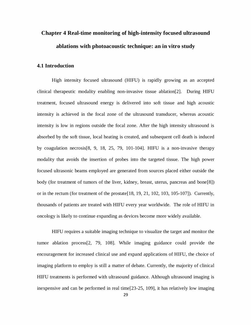
High intensity focused ultrasound (HIFU) is rapidly growing as an accepted
clinical therapeutic modality enabling non-invasive tissue ablation[2]. During HIFU
treatment, focused ultrasound energy is delivered into soft tissue and high acoustic
intensity is achieved in the focal zone of the ultrasound transducer, whereas acoustic
intensity is low in regions outside the focal zone. After the high intensity ultrasound is
absorbed by the soft tissue, local heating is created, and subsequent cell death is induced
by coagulation necrosis[8, 9, 18, 25, 79, 101-104]. HIFU is a non-invasive therapy
modality that avoids the insertion of probes into the targeted tissue. The high power
focused ultrasonic beams employed are generated from sources placed either outside the
body (for treatment of tumors of the liver, kidney, breast, uterus, pancreas and bone[8])
or in the rectum (for treatment of the prostate[18, 19, 21, 102, 103, 105-107]). Currently,
thousands of patients are treated with HIFU every year worldwide. The role of HIFU in
oncology is likely to continue expanding as devices become more widely available.
HIFU requires a suitable imaging technique to visualize the target and monitor the
tumor ablation process[2, 79, 108]. While imaging guidance could provide the
encouragement for increased clinical use and expand applications of HIFU, the choice of
imaging platform to employ is still a matter of debate. Currently, the majority of clinical
HIFU treatments is performed with ultrasound guidance. Although ultrasound imaging is
inexpensive and can be performed in real time[23-25, 109], it has relatively low imaging

30
contrast, sensitivity, and specificity for noninvasive detection. In addition, temperature
rise during HIFU cannot yet be accurately measured with ultrasound, especially when
cavitation occurs, although efforts have been made[26-30]. In some respects, magnetic
resonance imaging (MRI) is a more viable imaging technique to guide HIFU therapy
because it can produce temperature images[8, 22, 80-82]. However, MRI makes the
treatment expensive. In addition to the high equipment and operating costs, MRI requires
the patient to be placed inside a magnet. The magnet bore restricts patient access for
HIFU treatment and complicates positioning of the HIFU applicator. In some MRI modes
(such as head and neck imaging), special RF coils are used to fit closely to the patient’s
anatomy, and these coils will interfere with HIFU transducer placement.
Photoacoustic imaging (PAI), also called optoacoustic imaging or thermoacoustic
imaging, has been developed as a novel promising imaging technique for early cancer
detection[37-41, 44]. PAI is based on the generation of photoacoustic waves by safely
depositing short-pulsed optical energy into tissue, and then detecting these waves with a
diagnostic imaging transducer, acting as a receiver to uncover local tissue
abnormalities[42-44]. PAI overcomes the limitations of other existing modalities and
combines optical contrast with ultrasonic resolution. PAI has demonstrated imaging
depth up to 5 cm[45] with the imaging resolution (from 2 µm to 500 µm) scalable to the
imaging depth[42, 110]. Because PAI is based on optical absorption, it can be
implemented quickly and inexpensively, with relatively simple instrumentation
requirements and no ionization.

31
PAI has demonstrated the capability to monitor thermal lesions generated by
HIFU or other means[47-50, 87, 111]. However, all study up to date was focused on the
monitoring of temperature with PAI during HIFU. Although PA signals are sensitive to
temperature rise, monitoring temperature with PAI during HIFU may not provide
accurate indication for tissue coagulation. The generation of PA signals depends on the
optical properties of the sample. PA signals will change if the optical properties of the
sample changes. For example, tissue samples may coagulate at a constant temperature,
e.g. 50 oC, and therefore, the optical properties of tissue sample will change under the
constant temperature. As a result, PA signals will change at this constant temperature. In
other words, PA signals are related to heating rate, and the signal amplitude is a function
of temperature and heating duration, which are coupled parameters during the
coagulation process and cannot be separated. Therefore, the utilization of PAI to
monitoring temperature rise during thermal ablation without considering heating duration
may not be possible.
In this paper, we propose to use PAI to monitor thermal dose, which is a function
of heating duration and temperature, and a direct indicator for tissue coagulation, during
HIFU exposure. We employed an integrated PAI and HIFU system we developed
previously[112] to monitor HIFU ablation on beef kidney in real time. Two ultrasonic
focused transducers were employed to deliver HIFU energy and receive photoacoustic
signals. Temperature rise during HIFU ablation was also measured with a thermocouple
and the thermal dose was calculated. Therefore, PA signals were related to tissue
coagulation through thermal dose. We demonstrated that a relationship between PA

32
signal amplitude and thermal dose should be developed and used to monitor thermal
ablation.
4.2 Materials and methods
Figure 4.1 Diagram of experimental setup.
The experimental setup is shown in Figure 4.1. A tunable Optical parametric
oscillator (OPO) laser (Surelite OPO PLUS; Continuum, Santa Clara, CA), pumped by a
Q-switched Nd:YAG laser (Surelite; Continuum, Santa Clara, CA) with a pulse repetition
rate of 10 Hz, was employed as the irradiation source. The generated laser pulses were
directed by three prisms and then formed a ring-shaped illumination by a conical lens. A
condenser lens was used to make the laser light confocal with a 5-MHz HIFU transducer
(SU-108-013; Sonic Concepts, Bothell, WA) which was mounted in the middle of the
condenser lens. A 10-MHz focused ultrasonic transducer (37.5 mm focal length; 65.81%
33
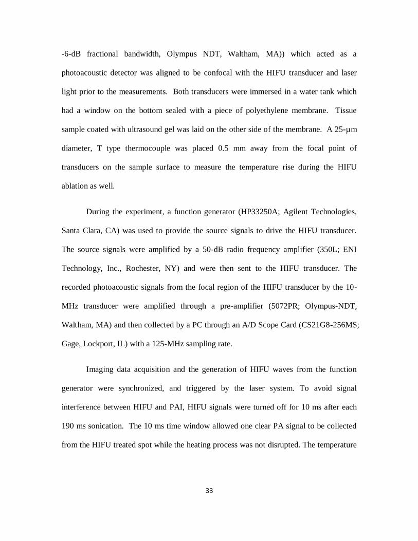
-6-dB fractional bandwidth, Olympus NDT, Waltham, MA)) which acted as a
photoacoustic detector was aligned to be confocal with the HIFU transducer and laser
light prior to the measurements. Both transducers were immersed in a water tank which
had a window on the bottom sealed with a piece of polyethylene membrane. Tissue
sample coated with ultrasound gel was laid on the other side of the membrane. A 25-µm
diameter, T type thermocouple was placed 0.5 mm away from the focal point of
transducers on the sample surface to measure the temperature rise during the HIFU
ablation as well.
During the experiment, a function generator (HP33250A; Agilent Technologies,
Santa Clara, CA) was used to provide the source signals to drive the HIFU transducer.
The source signals were amplified by a 50-dB radio frequency amplifier (350L; ENI
Technology, Inc., Rochester, NY) and were then sent to the HIFU transducer. The
recorded photoacoustic signals from the focal region of the HIFU transducer by the 10-
MHz transducer were amplified through a pre-amplifier (5072PR; Olympus-NDT,
Waltham, MA) and then collected by a PC through an A/D Scope Card (CS21G8-256MS;
Gage, Lockport, IL) with a 125-MHz sampling rate.
Imaging data acquisition and the generation of HIFU waves from the function
generator were synchronized, and triggered by the laser system. To avoid signal
interference between HIFU and PAI, HIFU signals were turned off for 10 ms after each
190 ms sonication. The 10 ms time window allowed one clear PA signal to be collected
from the HIFU treated spot while the heating process was not disrupted. The temperature

34
induced by HIFU was monitored at the same time with the T-type thermocouple. Figure
4.2 shows the time sequence of imaging data acquisition and HIFU treatment.
Figure 4.2 Time sequence of data acquisition and HIFU waves.
Thermal dose was calculated using the formula suggested by Sapareto and Dewey
[113]. Thermal dose at 43˚C is given by the relationship:
TD43 = R43−T∆tt=finalt=0 (1)
where TD43 is the equivalent time at 43°C, R is 0.5 when T is above 43˚C and
0.25 when T is below 43˚C, T is the temperature during Δt. A thermal dose of 240
equivalent minutes at 43 ˚C is widely regarded as the critical value for tissue coagulation.
4.3 Results and Discussion

35
Figure 4.3 Results from five separated experiments with an intensity of 1000W/cm2, 14s
duration. (a), (b) the averaged PA amplitude and temperature with standard error of the
mean (SEM), respectively, (c) the relation between the PA amplitude and the calculated
thermal dose from the averaged temperature, and (d) photographs of beef kidney after
HIFU treatment.
Figure 4.3 shows the averaged results of five experiments with an HIFU focal
intensity of 1000 W/cm2 and 14-second duration in different beef kidney samples. In
Figure 4.3(a) and (b), the averaged PA amplitude and measured temperature with
standard error of the mean (SEM) are presented, where SEM shows the range for the
averaged PA amplitude. In the beginning part of the HIFU ablation, both the PA

36
amplitude and temperature keep increasing. After about 8 s, the PA amplitude and
temperature tends to reach a constant value because the targeted area of the sample is
fully coagulated. Figure 4.3(c) shows the PA amplitude as a function of calculated
thermal dose from measured temperatures by the T-type thermocouple. It shows that the
relative constant amplitude occurs at TD43 of around 240 minutes at 43 ˚C, which
indicates the coagulation of tissue. Additionally, in comparison with the beginning of the
ablation, PA signal amplitude increased 3 times at the end of HIFU ablation. This result
implies that PA detection is highly sensitive to detect HIFU ablation. Figure 4.3(d)
shows the photograph of the lesion generated under this exposure which was on the
surface of the renal cortex tissue of beef kidney.
As we have mentioned previously, HIFU ablation process is a dynamic process,
and the tissue property change, which results in the change in PA amplitude, is a function
of both temperature and heating duration. An experiment such as the one shown in
Figure 4.3 shows the combined effect of both temperature and heating duration. To
separate the effect of these two factors on PA signals, we conducted the follow
experiments.
To monitor the sole effect of temperature, we used HIFU to ablate the targeted
sample for 40 s at 1000 W/cm2 focal intensity to make sure the targeted tissue is fully
coagulated, i.e., no more tissue property change even if the high temperature is
maintained. Then HIFU was turned off, and both PA signals and temperatures were
recorded during the cooling stage. Because the tissue sample was already completely

37
coagulated, the changes in PA signals were purely induced by the changes of temperature
during this process. Figure 4.4 shows the recorded PA amplitude as the function of
temperature. We can observe a linear relation between PA amplitude and temperature.
This liner relationship is not unexpected because it has been shown by others in vitro
[114].
Figure 4.4 PA amplitude as the function of temperature and the linear fit. The coefficient
of determination R2=0.8727.
To monitor the sole effect of heating duration, we placed a piece of beef kidney (3
mm thick) into a constant 50˚C water bath. PA signals generated from the surface of the
beef kidney were monitored continuously. A T-type thermocouple was also placed at the
tissue surface to monitor the temperature. Throughout the experiment, the temperature at
the tissue surface stayed at 50 C 0.2 C. The recorded PA amplitude is presented in
Figure 4.5. From Figure 4.5(a), we observe that PA amplitude increases initially and then

38
after about 3 minutes, PA signals stays at a constant level. Figure 4.5 (b) shows the
calculated thermal dose, which shows that PA amplitude stays relative constant beginning
around 240 TD43 minutes, which indicates the tissue is fully coagulated.
Figure 4.5 (a) PA amplitudes from a beef kidney sample placed in a 50˚C temperature
water bath; (b) the relation between the PA amplitude and the calculated thermal dose.
Figure 4.5 indicates that PA amplitude changes under a constant temperature over
an appreciate time. This result is not unexpected because tissue coagulation occurs at a
constant temperature, e.g. 50 C, and tissue optical properties change during the
coagulation. As a result, PA signals will change. Therefore, it may not be proper to
monitor the temperature changes during HIFU ablation by using PA signal amplitude
because HIFU ablation may not induce instantaneous change in temperature. If HIFU
treatment could induce nearly-instantaneously temperature rise, then PA detection would
be accurate correlated to temperature at the beginning stage of the treatment.
39
4.4 Conclusion
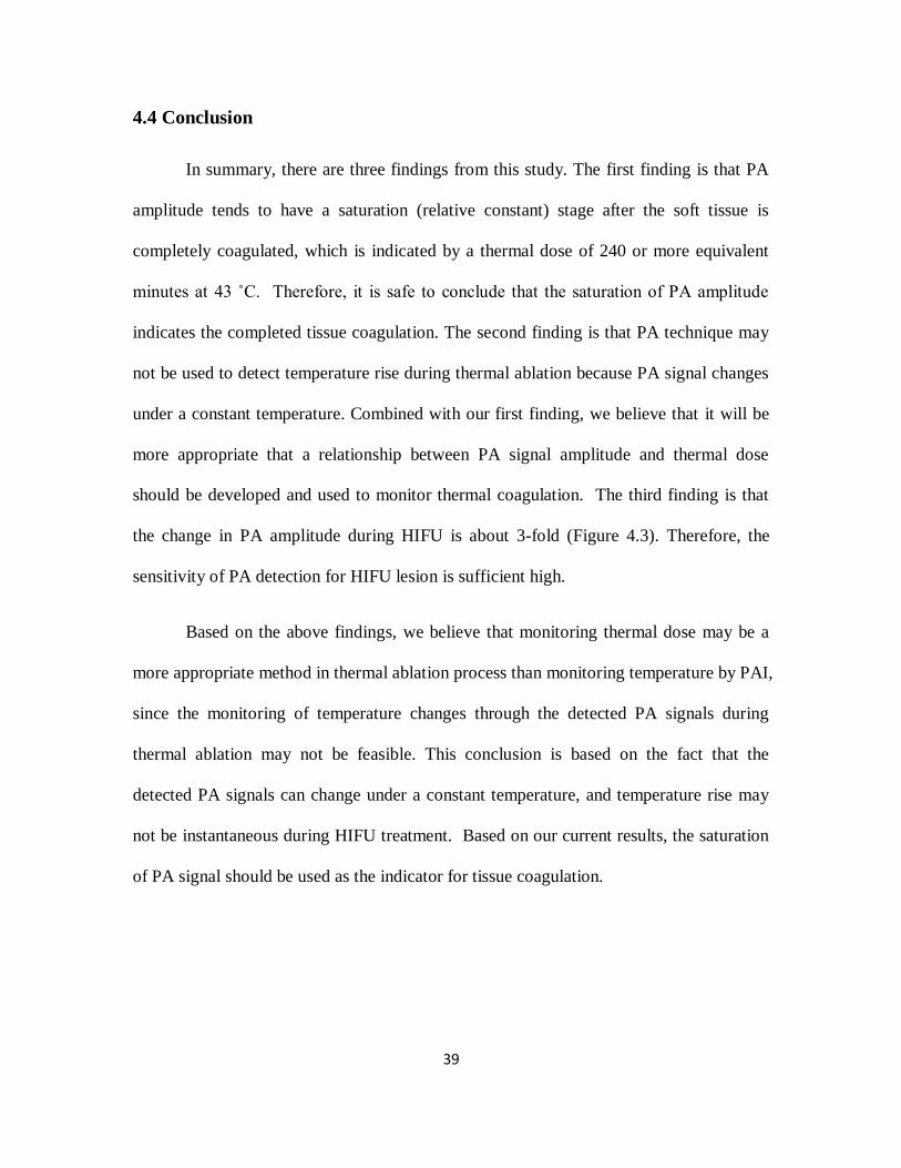
In summary, there are three findings from this study. The first finding is that PA
amplitude tends to have a saturation (relative constant) stage after the soft tissue is
completely coagulated, which is indicated by a thermal dose of 240 or more equivalent
minutes at 43 ˚C. Therefore, it is safe to conclude that the saturation of PA amplitude
indicates the completed tissue coagulation. The second finding is that PA technique may
not be used to detect temperature rise during thermal ablation because PA signal changes
under a constant temperature. Combined with our first finding, we believe that it will be
more appropriate that a relationship between PA signal amplitude and thermal dose
should be developed and used to monitor thermal coagulation. The third finding is that
the change in PA amplitude during HIFU is about 3-fold (Figure 4.3). Therefore, the
sensitivity of PA detection for HIFU lesion is sufficient high.
Based on the above findings, we believe that monitoring thermal dose may be a
more appropriate method in thermal ablation process than monitoring temperature by PAI,
since the monitoring of temperature changes through the detected PA signals during
thermal ablation may not be feasible. This conclusion is based on the fact that the
detected PA signals can change under a constant temperature, and temperature rise may
not be instantaneous during HIFU treatment. Based on our current results, the saturation
of PA signal should be used as the indicator for tissue coagulation.
40
Chapter 5 Enhanced-heating effect during photoacoustic imaging-
guided high-intensity focused ultrasound
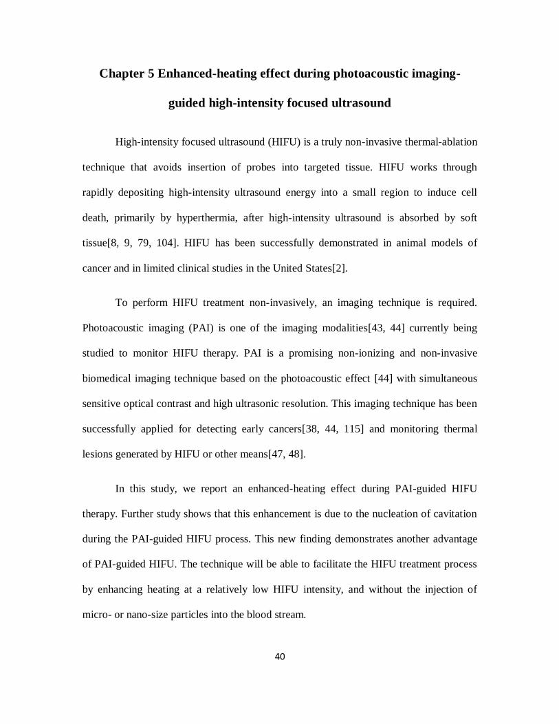
High-intensity focused ultrasound (HIFU) is a truly non-invasive thermal-ablation
technique that avoids insertion of probes into targeted tissue. HIFU works through
rapidly depositing high-intensity ultrasound energy into a small region to induce cell
death, primarily by hyperthermia, after high-intensity ultrasound is absorbed by soft
tissue[8, 9, 79, 104]. HIFU has been successfully demonstrated in animal models of
cancer and in limited clinical studies in the United States[2].
To perform HIFU treatment non-invasively, an imaging technique is required.
Photoacoustic imaging (PAI) is one of the imaging modalities[43, 44] currently being
studied to monitor HIFU therapy. PAI is a promising non-ionizing and non-invasive
biomedical imaging technique based on the photoacoustic effect [44] with simultaneous
sensitive optical contrast and high ultrasonic resolution. This imaging technique has been
successfully applied for detecting early cancers[38, 44, 115] and monitoring thermal
lesions generated by HIFU or other means[47, 48].
In this study, we report an enhanced-heating effect during PAI-guided HIFU
therapy. Further study shows that this enhancement is due to the nucleation of cavitation
during the PAI-guided HIFU process. This new finding demonstrates another advantage
of PAI-guided HIFU. The technique will be able to facilitate the HIFU treatment process
by enhancing heating at a relatively low HIFU intensity, and without the injection of
micro- or nano-size particles into the blood stream.

41
Figure 5.1 System schematic.
Figure 5.1 shows the schematic of the PAI-guided HIFU system. A tunable
optical parameter oscillator (OPO) laser (Surelite OPO PLUS, Continuum, CA), pumped
by a Q-switched Nd:YAG laser with a pulse repetition rate of 10 Hz, was employed as
the irradiation source. The generated laser pulses were directed by a couple of prisms,
and then formed into a ring-shaped illumination by a conical lens. A condenser lens was
used to make the laser light confocal with a 5-MHz HIFU transducer (SU-108-013, Sonic
Concepts, WA) (35 mm focal length), which was mounted in the middle of the condenser
lens. A 10-MHz focused ultrasonic transducer (V315, Olympus NDT, MA) (37.5 mm
focal length; 70% -6-dB fractional bandwidth), which acted as a photoacoustic signal
detector, was aligned to be confocal with the HIFU transducer and laser light prior to the
measurements. The 10-MHz PA detector can also be used as a passive cavitation detector

42
(PCD) to detect cavitation events by sensing the broadband acoustic emissions generated
by the collapse of bubbles during HIFU ablation. Both 10-MHz and 5-MHz transducers
were immersed in a water tank, which had a window on the bottom. The window was
sealed with a polyethylene membrane. Samples coated with ultrasound gels were laid on
the other side of the membrane. A 50-µm diameter, T-type thermocouple was inserted
into the tissue sample through a needle and placed 0.5 mm away from the focal point of
the HIFU transducer to measure the temperature rise during the HIFU ablation. In all
experiments, beef kidney samples were used. The laser intensity on the tissue surface was
measured to be 18 mJ/cm2.
During the experiment, a function generator (HP33250A, Agilent Technologies,
CA) was used to provide the source signals to drive the HIFU transducer. The source
signals were first amplified by a 50-dB radio frequency amplifier (350L, ENI Technology,
Inc., NY), and then sent to the HIFU transducer in order to induce thermal lesions in the
sample. During PAI-guided HIFU, burst HIFU waves with 95% duty cycle were
transmitted by the HIFU transducer with a repetition rate of 5 Hz in order to avoid signal
interference from HIFU on PAI. Therefore, a clear PA signal could be collected by the
10-MHz transducer at 5 Hz when the HIFU waves were off. Because the laser system
was running at 10 Hz, 50% of the laser shots illuminated the tissue sample when HIFU
was running. During the PAI-guided HIFU model, signals from these 50% of the laser
shots were discarded due to the strong interference between the HIFU waves and the PA
signals.

43
Figure 5.2 Temperature enhancement during PAI-guided HIFU. Lines with stars and
circles represent the temperature measured by a T-type thermocouple during HIFU
exposure when PAI system was on and off, respectively.
During temperature measurement, we found that there was a temperature
enhancement when the laser system was operating (PAI was on) during HIFU ablation.
Figure 5.2 shows an example of the measured average temperature with standard
deviation (STD) from five HIFU sonications through the T-type thermocouple. In these
measurements, HIFU focal intensity level was 1000 W/cm2, and the sonication duration
was 20 seconds. Although no temperature rise could be observed when the PAI system
was operating alone, (i.e., HIFU exposure was stopped), there was clearly a temperature
enhancement of ~15 C when the PAI system was operating during HIFU exposure. This

44
result indicates that the HIFU heating is significantly enhanced by the assistance of laser
light.
Figure 5.3 Photograph of HIFU lesions inside a tissue sample after HIFU exposure.
After HIFU exposure, the tissue sample was cut open, and a photograph of the
lesions was taken. Figure 5.3 shows a photograph of HIFU lesions inside the tissue
sample. Each HIFU lesion was induced by a single HIFU sonication. We can clearly
observe that the sizes of the HIFU lesions are bigger when the PAI system is on in
comparison with that of when the PAI system is off. In addition, from one example, the
measured lesion volumes were 3.52 mm3 (with the laser on) and 1.43 mm
3 (with the laser

45
off), respectively. This result shows great enhancement in HIFU ablation due to the
presence of laser light. The histological results further confirm that HIFU heating is
enhanced when PAI and HIFU systems are operating concurrently. Additionally, empty
cavities were observed in the central region of the HIFU lesions and suggested that
cavitation might have occurred during the heating process when the laser system
concurrently illuminated the sample.
To further confirm the occurrence of cavitation and explain the enhanced heating
during PAI-guided HIFU, the 10-MHz photoacoustic detector was used as a PCD [51] to
detect broadband acoustic emission from the HIFU focal zone. During this test, HIFU
was running continuously with different focal intensities and sonication duration of 20 s,
and PCD signals were collected with the laser system on and off. The PCD received two
types of signals. The first type of signals was sound scattered by the tissue sample, which
consisted of primary 5-MHz waves from HIFU. The second type of signals was sound
emission from cavitation, which consisted of higher harmonics of the 5-MHz waves. In
order to separate the emissions of cavitation from the 5 MHz HIFU waves, a 10-MHz
high-pass filter was used. With this system, an abrupt increase in higher harmonics of the
5-MHz waves could appear in the signal spectra when cavitation occurred. For data
collection, detected PCD time-domain signals were amplified by a pre-amplifier (5072PR,
Olympus-NDT, MA), captured by the GageScope (CS21G8-256MSn Gage, IL), and then
downloaded to a personal computer. At each HIFU intensity level, five HIFU lesions
were induced on the sample by five HIFU sonications. The number of HIFU lesions with
acoustic cavitation at different HIFU intensity levels was counted, and the results are
shown in Table 5.1. It is shown that acoustic cavitation occurred at a lower HIFU

46
intensity (800 W/cm2) with the laser illumination. However, without the laser
illumination, cavitation would not occur until the HIFU intensity reached 1700 W/cm2.
Cavitation has been demonstrated to enhance HIFU heating by increasing the effective
ultrasound absorption[116]. Therefore, the HIFU heating enhancement at a relatively low
HIFU intensity when the PAI system was operating in this study was due to the induced
acoustic cavitation in soft tissue.
Table 5.1 Number of HIFU lesions with cavitation from five HIFU sonications at each
HIFU intensity level with laser on and off.
Laser on Laser off
HIFU
intensity
(W/cm2)
Number of lesions with
cavitation
HIFU intensity
(W/cm2)
Number of lesions with
cavitation
600 0 1500 0
700 0 1600 0
800 3 1700 4
900 5 1800 5
1000 5 1900 5
While the application of HIFU therapy is expanding, the concerns related to HIFU
treatment include prolonged treatment time for large tumors and skin burns. To reduce
the prolonged treatment, it is necessary to enhance the heating induced by HIFU exposure.
In general, to enhance HIFU heating, we can simply employ ultrasound waves with
higher intensity levels. However, high-power output will induce severe skin burns and
also present great challenges for the design of the HIFU system, including the design of

47
transducers and the electronic circuits. An alternative to very high ultrasound intensity is
to increase the local ultrasound absorption so that more ultrasound energy can be
deposited in the local region at a relatively low HIFU intensity level. The introduction of
cavitation has been investigated as a mechanism to increase the local ultrasound
absorption and enhance heating in HIFU [51, 52]. Cavitation has been shown to yield
elevated heating rates above those produced by classical absorption in tissue [117, 118]
and can provide a means for improving the efficacy of HIFU treatment. However, pre-
existing nucleation sites for cavitation are not omnipresent in most tissues in vivo. Either
ultrasound contrast agents (UCA) [66, 119, 120] or nanoparticles have been studied as
methods of delivering nuclei into the target region[52]. The use of UCA and
nanoparticles, however, requires the systematic injection of foreign particles into the
blood stream, and would cause much concern regarding the toxicity, efficiency, etc.
This letter reports a particle-free, photo-enhanced HIFU heating method with the
utilization of a diagnostic laser system. HIFU heating was enhanced through inducing
cavitation in soft tissue by the combination of laser light and ultrasound. In comparison
with the other means to enhance HIFU heating, the current technique does not involve the
use of any nanoparticles or UCA. The other advantage of the current technique is that a
diagnostic laser system for PAI can be used. Therefore, the heating enhancement can be
easily achieved while the treatment process is monitored by PAI.

48
Chapter 6 Laser-enhanced cavitation during high intensity focused
ultrasound: an in vivo study
6.1 Introduction
High intensity focused ultrasound (HIFU) is a truly non-invasive thermal-ablation
technique. HIFU works through rapidly depositing high intensity ultrasound energy into a
small region to induce cell death primarily by hyperthermia after high intensity
ultrasound is absorbed by soft tissue[8, 9, 79]. While the application of HIFU therapy is
expanding, one concern related to HIFU treatment is the prolonged treatment time for
large tumors because HIFU lesion is relatively small for each HIFU shot.
Cavitation has been shown to yield elevated heating rate above those produced by
classical acoustic absorption in tissue[51, 117, 118, 121-123] and can provide an
effective method to improve the efficiency of HIFU treatment. However, pre-existing
nucleation sites for cavitation are not omnipresent in most tissues in vivo. Many research
efforts have been made to create nucleation sites for cavitation and reduce cavitation
threshold. Both ultrasound contrast agents (UCA)[66, 67, 119, 120, 124, 125] and
nanoparticles have been studied as methods to deliver cavitation nuclei into the targeted
region[52, 100]. The use of UCA or nanoparticle, however, requires the systematic
injection of foreign particles into the blood stream, and would have a lot of concerns
regarding the toxicity, efficiency, etc.
Laser light has been widely used to induce cavitation through optical breakdown.
This procedure is generally performed with high intensity light, and mostly limited to

49
clear media or sample surfaces[126, 127]. Hence the application of this technique is
limited in the in vivo applications, where treatments in a certain depth in turbid media are
often desired.
In a previous study[128], we reported an enhanced heating effect during
photoacoustic imaging-guided HIFU therapy. The results suggested that cavitation was
enhanced when a diagnostic laser light beam illuminated the sample concurrently with
HIFU radiation. Two features were highlighted in this previous study: 1)a diagnostic
laser light beam was used, and the laser fluence was low and under the safety limit
recommended by American National Standards Institute[129]; 2) cavitation was observed
under the surface layer in a turbid medium. These results motivate us to further study the
feasibility of laser-enhanced cavitation during HIFU, and test the limit of this technique.
In the current study, we further investigated laser-enhanced cavitation effect
during HIFU in an in vivo experiment. Specifically, we investigated the effect of laser on
cavitation threshold as a function of laser wavelength, HIFU duration, and treatment
depth. The significance of this study lies in the fact that it may develop a technique to
facilitate cavitation during HIFU with a diagnostic laser system; hence, HIFU heating can
be enhanced without introducing foreign particles into the targeted tissue region.
6.2 Materials and Methods
6.2.1 Experimental system

50
Figure 6.1 System schematic.
A block diagram of experimental setup is shown in Figure 6.1. A Q-switched,
Nd:YAG laser pumped, tunable optical parameter oscillator (OPO) laser (Surelite OPO
PLUS, Continuum, Santa Clara, CA) with a pulse repetition rate of 10 Hz (5-ns pulse
width), was employed as the irradiation source. The generated laser beam was formed
into a ring-shaped illumination on a condenser lens, which was used to mount a 5-MHz
HIFU transducer (SU-108-013, Sonic Concepts, Bothell, WA) (35 mm focal length) in
the center hole. The condenser lens focused the laser beam underneath the HIFU
transducer, and the optical focus overlapped with the ultrasound focus. A 10-MHz
focused ultrasonic transducer (V315, Olympus-NDT, Waltham, MA) (37.5 mm focal
length; 70% -6-dB fractional bandwidth), which was placed at a 90-degree angle with the

51
HIFU transducer and acted as a passive cavitation detector (PCD), was aligned to be
confocal with the HIFU transducer and the laser beam prior to HIFU treatments. The
signal detected by the PCD was directed to a pre-amplifier (5072PR; Olympus-NDT,
Waltham, MA).Then, the resulting signals were captured by a data acquisition card
(GageScope, CS21G8-256MSn Gage, Lockport, IL), and filtered by a 10-MHz high-pass
filter to remove contributions from the HIFU fundamental and second harmonic
frequencies in order to ensure that the detected signals were mainly received from
broadband acoustic emissions of cavitation. Both the 10-MHz and 5-MHz transducers
were immersed in a water tank that has a window on the bottom. The water tank was
filled with degassed water, and the window at the bottom was sealed by a piece of
polyethylene membrane.
During each experiment, the source signals were generated by a function
generator (HP33250A, Agilent Technologies, Santa Clara, CA), and amplified by a 50-
dB radio frequency amplifier (350L, ENI Technology, Inc., Rochester, NY), before they
were sent to the HIFU transducer through a matching network to induce cavitation in the
sample. Laser light was applied to the sample surface concurrently with HIFU
sonications.
6.2.2 In vivo experiment
During the in vivo experiment, mice (BALB/c, 8-10 weeks old, female or male)
were used. All animals have been handled and cared for in accordance with the Guide for
the Care and Use of Laboratory Animals, and the procedures were approved by the
Institutional Animal Care and Use Committee at the University of Kansas. Before each

52
experiment, one animal was anesthetized with a mixture of ketamine (87 mg/kg body
weight) and xylazine (13 mg/kg body weight) and shaved in the leg region. The shaving
procedure included the use of standard surgical hair removal lotion because hairs
interfere with ultrasound propagation. After shaving, the animal was maintained under
anesthesia with an isoflurane gas anesthesia machine (1-2% isoflurane in pure oxygen)
for at least one hour to allow the animal to reach equilibrium body condition. Surgical
tape was used to gently secure the animal onto a warmed pad. A custom-designed animal
holder was also used to fix the animal with ear-pins and a tooth-pin. The animal was then
secured underneath the membrane at the bottom of the water tank for the subsequent
experiment. Ultrasound coupling gel was applied to the top surface of the sample to
provide coupling between the membrane and the sample surface. Heart−rate and blood
oxygenation were monitored with a pulse−oximeter during the experiment, and breathing
was visually monitored.
During the experiment, different combinations of laser intensities and ultrasound
pressures were applied to the leg muscle of the animal, and the generated cavitation
signals were detected by the PCD to determine the pressure thresholds[118] for cavitation.
Laser wavelengths in near-infrared region such as 760 and 960 nm were used in order to
achieve deep penetration depth.
To obtain HIFU pressure inside the tissue sample, we first calibrated the HIFU
transducer with a standard hydrophone, and then a simulation process was employed to
calculate the HIFU focal pressure in the tissue sample. During the simulation process, a
finite difference time domain (FDTD)[130] was used. The laser fluence was first

53
measured at the surface of the tissue sample. Then Beer’s law was used to estimate the
laser fluence inside the tissue by assuming a diffusion process[131].
In order to test the capability of generating cavitation at different depths, we used
chicken breast tissues with different thicknesses to cover the region of interest on the
small animal. During the experiment, the confocal point of the transducers and the laser
was carefully aligned into a leg of the small animal at the desired depths, which were 5
mm and 10 mm from the top sample surface in this study.
6.3 Results
The measured cavitation thresholds are shown in Figure 6.2. Figure 6.2(a) shows
the measured cavitation threshold at 5 mm depth when the laser wavelength is 760 nm
with a 2-second HIFU sonication. The result shows that the cavitation threshold
decreases as the laser fluence increases. When no laser is applied, the detected cavitation
threshold is 9.80 MPa. When the surface laser fluence is increased to 50 mJ/cm2, which
corresponds to a fluence of 10.7 mJ/cm2in the HIFU focal region, the measured cavitation
threshold is reduced to 7.89 MPa. Figure 6.2(b) shows the results with the similar
parameter settings but the HIFU treatment depth is 10 mm. At this depth, the measured
cavitation threshold is similar between with and without laser (10.43 MPa verses 10.31
MPa). By using Beer’s law, we estimate that the laser fluence at the HIFU focal spot is
only 2.3 mJ/cm2, which is very low and may explain the reason why laser has little effect
on enhancing cavitation.
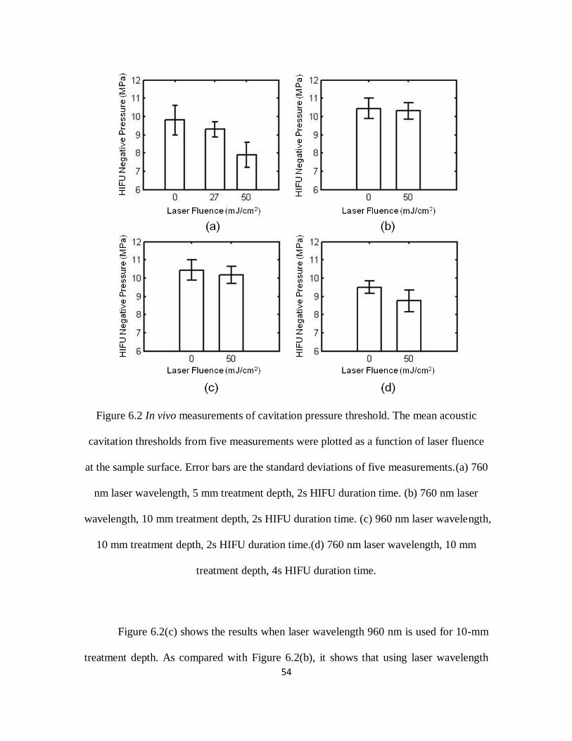
54
Figure 6.2 In vivo measurements of cavitation pressure threshold. The mean acoustic
cavitation thresholds from five measurements were plotted as a function of laser fluence
at the sample surface. Error bars are the standard deviations of five measurements.(a) 760
nm laser wavelength, 5 mm treatment depth, 2s HIFU duration time. (b) 760 nm laser
wavelength, 10 mm treatment depth, 2s HIFU duration time. (c) 960 nm laser wavelength,
10 mm treatment depth, 2s HIFU duration time.(d) 760 nm laser wavelength, 10 mm
treatment depth, 4s HIFU duration time.
Figure 6.2(c) shows the results when laser wavelength 960 nm is used for 10-mm
treatment depth. As compared with Figure 6.2(b), it shows that using laser wavelength

55
960nm reduces the cavitation threshold slightly more than using 760 nm wavelength,
although the differences are in the range of error. The major difficulty at this depth is that
the laser intensity drops to a very low level, and therefore, the enhancement effect on
cavitation threshold becomes low. However, longer wavelength lights should have
advantages to enhance cavitation in the deep region because that as the laser wavelength
increases in near-infrared (NIR) region, light can propagate further, and therefore retain
more energy in a certain treatment depth[132-134].
Figure 6.2(d) shows the measured cavitation thresholds at 10 mm depth with 760
nm laser wavelength and a 4-second HIFU sonication. When laser light is applied, the
cavitation cavitation threshold is reduced from 9.50 MPa to 8.76 MPa. As compared with
Figure 6.2(b), whereas the only difference is the duration of HIFU sonication, Figure
6.2(d) shows that laser-enhanced cavitation can be facilitated by longer HIFU sonication
duration.
6.4 Discussion and conclusions
In this study, we showed in vivo results for laser-enhanced cavitation effect during
HIFU. The results suggest that cavitation effect can be enhanced when laser light is
applied to the sample during HIFU sonications. The magnitude of the enhancement,
however, seems related to the applied laser fluence. The enhancement will be greater if
the applied laser fluence is higher. Laser wavelength and HIFU duration all have effects
on the detected cavitation threshold. The major limitation of this technique will be the
depth because light is strongly scattered in soft tissue.

56
Laser light is well-known for its ability to nucleate cavitation through
vaporization[127, 135]. To vaporize the surrounding fluid through either optical
absorption or optical breakdown, high optical intensity is needed. In this study, however,
we showed that with the combination of laser and ultrasound, cavitation was enhanced at
a relatively low optical fluence, which complies with the laser safety limit for human
recommended by American National Standards Institute[129]. Therefore, the cavitation
effect showed in this study is likely due to the combination effect of laser and ultrasound,
not laser alone.
In summary, concurrent light illumination during HIFU has the potential to
enhance cavitation by reducing cavitation threshold. In comparison with the other
methods to enhance HIFU, this technique does not involve the use of any nanoparticles or
ultrasound contrast agents.

57
Chapter 7 Laser enhanced high-intensity focused ultrasound
thrombolysis: an in vitro study
7.1 Introduction
Catheter-based ultrasound has been extensively studied as an efficient method to
treat deep venous thrombosis (DVT) clinically[53-59]. However, these methods require
the catheter to be placed within the blood clot in order to induce mechanical disruption
through oscillating wires at high frequency and high intensity. Although catheter-based
ultrasound provides an invasive way for thrombolysis, it has shown that the acoustic
energy has the ability to dissolve the clots into small debris without causing arterial
damage, which is the basis of non-invasive ultrasonic treatment.
High intensity focused ultrasound (HIFU) is one of the non-invasive methods to
primarily treat abnormal tissue thermally through hyperthermia[8, 9, 79]. In HIFU
ablation, a rapid temperature elevation due to high energy deposition rate results in the
tissue damage. However, in pulsed-HIFU exposures with low duty cycle, which is used
for thrombolysis, energy deposition rates are low enough that temperature rises are well
below the threshold for thermal damage. Thus, the effect of clot disruption are obtained
more mechanically and cavitation effect are considered to make the biggest contribution
during the process[54, 57, 60-62]. When cavitation occurs, the growth and collapse of
bubbles in a sound field at high frequencies produce microstreaming vortices in sufficient
magnitude, which can dissolve thrombus[136, 137].

58
The applications of thrombolysis by HIFU treatment alone are limited and have a
relatively low thrombolysis efficiency[63, 64], so either microbubbles or thrombolytic
drugs are applied during focused ultrasound exposure to enhance thrombolysis. The
addition of intravenously injected microbubbles can enhance the effects of ultrasound and
lower the energy requirement for producing ultrasound-mediated thrombolysis through
decreasing the cavitation threshold. This enhancement has been shown in several
studies[57, 62, 68, 69]. Also, a few of studies[138] have shown that HIFU can improve
thrombolysis while applying thrombolytic agent by reducing the dosage of the drug and
lowering the risk of hemorrhagic events, but increasing its efficacy. In addition,
microbubbles and thrombolytic drug can be combined together for targeted drug delivery,
drug transport acceleration[70-77] and eventually enhancing thrombolysis. However, the
use of microbubbles and thrombolytic drugs requires the systematic injection of foreign
particles into the blood stream, and would have a lot concerns regarding the toxicity,
efficiency, etc[78].
In our recent study[139], we found that when the laser system of photoacoustic
imaging (PAI) is running simultaneously with HIFU therapy, an enhanced heating effect
can be observed due to low cavitation threshold at a relatively low HIFU intensity. This
finding potentially allows us to enhance HIFU heating without introducing foreign
particles in to the targeted tissue region. Also, we expect that this discovery will be able
to get a wider range of applications, such as thrombolysis.
In this study, we further investigated the feasibility of laser-enhanced HIFU
therapy in the in vitro thrombolysis application. The effects of acoustic and laser

59
parameters (pulsed HIFU wave pulse length, pressure and laser intensity) were assessed.
More importantly, the thrombolysis efficiency were measured in both HIFU treatments
with and without laser illumination to explore the enhancement of HIFU thrombolysis.
7.2 Materials and Methods
7.2.1 Experimental system
Figure 7.1 System schematic.
The overall experimental arrangement is shown in Figure 7.1. The laser source
with a pulse repetition rate of 10 Hz (5-ns pulse width) consists of a pumped Q-switched,
Nd:YAG laser and a tunable optical parameter oscillator (OPO) laser (Surelite OPO
PLUS, Continuum, Santa Clara, CA). The generated laser beam was formed into a ring-

60
shaped illumination on a condenser lens and refocused underneath a 5-MHz HIFU
transducer (SU-108-013, Sonic Concepts, Bothell, WA) (35 mm focal length), which was
mounted on the condenser lens in the center hole. The focal point (-6 dB) of HIFU
transducer is 2.61×0.51×0.51 mm. A 10-MHz focused ultrasonic transducer (V315,
Olympus-NDT, Waltham, MA) (37.5 mm focal length; 70% -6-dB fractional bandwidth),
which was placed at a 90-degree angle with the HIFU transducer and acted as a passive
cavitation detector (PCD), was aligned to be confocal with the HIFU transducer and the
laser beam prior to HIFU treatments. The HIFU source waves were generated by a
function generator (HP33250A, Agilent Technologies, Santa Clara, CA), and amplified
by a 50-dB radio frequency amplifier (350L, ENI Technology, Inc., Rochester, NY),
before they were sent to the HIFU transducer through a matching network to induce
cavitation in the sample. The PCD signal was received by a pre-amplifier (5072PR;
Olympus-NDT, Waltham, MA) and captured by a data acquisition card (GageScope,
CS21G8-256MSn Gage, Lockport, IL) in the personal computer. A 10-MHz high-pass
filter was used to remove contributions from the HIFU fundamental and second harmonic
frequencies in order to ensure that the detected signals were mainly received from
broadband acoustic emissions of cavitation. Both the 10-MHz and 5-MHz transducers
were immersed in a water tank filled with degassed water during the treatment.
7.2.2 Clot preparation
Whole bovine blood mixed with CaCl2 in ~6 mm inner diameter tygon tubing,
was immersed in a 37ºC water bath for 2 hours and then stored at 4ºC for up to 3 days to
generate clots. Before the experiment, the clots cut into roughly cylindrical small pieces

61
with a diameter of 5 mm and a length of 5 mm were placed in a tygon tubing (6.25 mm
ID and 7.81 mm OD). The blood clots have a initial mass weight of 205±41 mg (n=155).
7.2.3 Experiment procedure
All experiments were conducted in a water container filled with degassed water.
Each blood clot were cut and weighted before the treatment and then placed in a tygon
tubing for exposure under HIFU transducer and laser light. During the sonication, HIFU
transducers, PCD detector and laser beams were driven by 3-D translation stages along x,
y and z directions. The predetermined speed of the movement along x direction was 0.25
mm/s and the step size for y and z directions were set to 0.5 mm and 1 mm according to
the size of the clot and HIFU transducer focal point. After the treatment, the clots were
flushed with saline solution on a 400 µm pore size filter for weighting. The difference
between the initial clot weight and the weight on the filter was used to calculate the
weight loss, which is thrombolysis efficiency, and expressed by percentage.
7.2.4 Assessment of ultrasound and laser parameters
The experiments were performed in 3 groups. Each group contained only one
variable (HIFU pulse length, HIFU pressure or laser fluence) with the other parameter
remained same in order to examine the influence of each variable on thrombolysis
efficiency. The treatment was repeated 5 times at each variable and performed both with
and without laser illumination for comparison. The duty cycle for all treatments was 1:10.
The laser wavelength used in this study was 760 nm.

62
7.3 Results and Discussion
Figure 7.2 Thrombolysis efficiency correlated with HIFU wave pulse length in the
treatment with and without laser radiation.
The mean thrombolysis efficiency was plotted as a function of pulse length in Figure 7.2.
The HIFU pressure and laser fluence used in this group was 13.2 MPa and 27 mJ/cm2,
respectively. This laser fluence at 760 nm laser wavelength was slightly higher than the
safety limit recommended by American National Standards Institute[129], which is 26.4
mJ/cm2. As we can see in the figure, longer pulse length yielded higher thrombolysis
efficiency until it tended to reach a saturation stage. With laser, the saturation point (800
µs pulse length) was reached earlier than it in the treatment without laser (1000 µs). In

63
the rise stage of the curves, the thrombolysis efficiency was greatly enhanced by laser. At
the pulse length of 800 µs, the enhancement was about 53.1%. To further investigate the
possible reason of this enhancement, acoustic cavitation signals were detected at each
pulse length by the transducer. It is shown that cavitation threshold in the treatments with
laser was at 400 µs pulse length. However, without the laser illumination, the cavitation
will not occur until the pulse length reached 1000 µs. As we know, cavitation has been
demonstrated to enhance thrombolysis effect. Therefore, the enhancement of HIFU
thrombolysis treatment was due to the laser-induced acoustic cavitation.
Figure 7.3 Thrombolysis efficiency measured under different HIFU pressures with and
without laser radiation.

64
To test the influence of HIFU pressure on thrombolysis efficiency, HIFU pulse
length (1000 µs) and laser fluence (27 mJ/cm2) were fixed. It is indicated in Figure 7.3
that at 5 and 7 MPa HIFU pressure, the thrombolysis efficiency were only about 21.1±3.0%
and 18.6±3.9%. However, as the HIFU pressure increases, a maximum of 74.2±2.8% clot
weight loss can be reached. Also, treatment with ultrasound alone produced less
thrombolysis than it with the presence of laser. In addition, acoustic cavitation can be
observed at 7 and 9 MPa with and without laser help. Thus, similarly, it is demonstrated
again that the laser illumination has successfully lowered cavitation threshold and
therefore enhanced the HIFU thrombolysis efficiency.
Figure 7.4 Thrombolysis efficiency with increasing laser fluence.

65
The increasing laser effect on thrombolysis effect was also examined as shown in
Figure 7.4. The HIFU pressure was determined to be 9.18 MPa and HIFU wave pulse
length was 1000 µs in these treatments. Acoustic cavitation threshold was observed at
laser fluence of 16 mJ/cm2. At laser fluence smaller than 16 mJ/cm
2, there was low
thrombolysis efficiency. However, as the laser fluence increased, a steep increase in
thrombolysis efficiency can be seen in the plot, which attributes the success to the laser
induced cavitation.
7.4 Conclusion
This study investigated the feasibility of using laser induced cavitation to enhance
in vitro HIFU thrombolysis treatment without any addition of thrombolytic agent or
microbubbles. Three important ultrasound and laser parameters (HIFU wave pulse length,
HIFU pressure, laser fluence) were chosen to test their influence on thrombolysis
efficiency. In most case, the larger the pulse length, HIFU pressure and laser fluence, the
better the thrombolysis efficiency can be obtained. The optimal parameters were a pulse
length of 1000 µs, HIFU pressure of 13 MPa and under 27 mJ/cm2 laser radiation, at
which a maximum thrombolysis efficiency (74.2±2.8%)were achieved. This in vitro data
will help to establish an optimal strategy for laser enhanced HIFU thrombolysis.
In addition, significant enhancement of thrombolysis efficiency was observed
with laser illumination. Laser induced cavitation was considered to be a primary factor in
the enhancement of HIFU thrombolysis treatment, because it is shown that cavitation
threshold was greatly reduced when laser was running concurrently with HIFU treatment.

66
We have shown in our previous study[139] that laser enhanced HIFU treatment
can be used in soft tissue thermal ablation. In this study, the results implied that this
technique without any external agent added has successfully shown another potential
application in the thrombolysis field. More future work is need to evaluate its in vivo and
clinical feasibility and potential risk of injury of vessel wall and surrounding tissue.

67
Chapter 8 Conclusion
8.1 Summary
The goal of this dissertation is to understand that photoacoustic imaging can be
performed to increase the accuracy and efficacy of HIFU treatment. Four main sections
were presented in this study. First, our results included the investigation of feasibility of
integrated PAI and HIFU system to guide HIFU thermal necrosis both ex vivo and in
vivo. Second, the real time PAI monitoring HIFU was applied for accurate evaluation of
thermal ablation outcomes. Third, during PAI monitoring HIFU, a significant
enhancement of both temperature elevation and lesion size were found, therefore, laser
enhanced HIFU treatment were presented with cavitation detection. Finally, we expanded
this laser enhanced technique to thrombolysis application. The results obtained from
above four applications form the primary contribution of this dissertation, which is to
demonstrate photoacoustic imaging, other than ultrasound imaging and MRI, can not
only be used to guide, monitor HIFU treatment, but also improve HIFU treatment by
enhancing cavitation effect.
8.2 Findings
According to the obtained results for the four sections, we concluded a set of
findings.
In the first section, an integrated PAI and HIFU system was developed and used
to treat soft tissue. Based on the successful experience with ex vivo experiment, the in
vivo HIFU ablation on tumors was performed. In the in vivo experiment, gold nanorods

68
was employed as a contrast agent to enhance the target imaging contrast. Two weeks
after the treatment, the tumor on the leg area of the BALB/c mouse cannot be observed
and the lesion was healed. The outcome of both ex vivo and in vivo PAI guided HIFU
ablation is to prove that it is feasible for PAI to be a guidance and evaluation tool for
HIFU therapy.
Generally, the transducers used in treatment operate in the 1-10 MHz frequency
range, with 2-4 MHz being the most common. However, a HIFU transducer with 5 MHz
central frequency was used throughout this work. The reason of choosing 5 MHz is that
the HIFU transducer in this study was not only acted as an ultrasound transmitter, but
also a photoacoustic signal receiver. Thus, choosing 5 MHz central frequency can allow
us to find a balance between transducer sensitivity (energy delivery) and imaging quality
(axial resolution).
The second section is to find out a better way to monitor HIFU ablation in soft
tissue in real time. Currently, all studies were using temperature change to estimate the
tissue necrosis, and the temperature was measured indirectly by using the change of
sound speed. However, the drawback is that the sound speed measurement may not be
accurate since the tissue property changes during the heating. Thus, the temperature
measurement is not a reliable methods for tissue coagulation. In our experiment, a 10
MHz ultrasonic transducer was added to the system for receiving photoacoustic signals
between two HIFU burst cycles to eliminate the interference of strong HIFU signals. The
results showed that PA amplitude increased during HIFU and finally reached a saturation
stage, which was an indication of complete tissue coagulation. The third finding is that

69
the change in PA amplitude during HIFU is about 3-fold (Fig.9). Therefore, the
sensitivity of PA detection using 5-MHz HIFU transducer seems very high.
In the third section, we found that HIFU heating is enhanced when PAI technique
is used to monitor HIFU lesion formation. We tested this technique both in ex vivo soft
tissue and in vivo mice tissue. The 10 MHz transducer was not used as a photoacoustic
signal detector but a passive cavitation detector. It is observed in the ex vivo experiment
that a 15ºC temperature difference and a larger lesion volume when laser was running
concurrently with HIFU heating. In the in vivo measurement, the cavitation pressure
threshold was significantly lowered when laser presented. It seems that the laser
illumination is the key for the heating enhancement. The possible reason for the
enhancement is due to the decrease of cavitation threshold at a relatively lower HIFU
pressure.
Finally, in the fourth section, we tested the laser enhance HIFU therapy in the
pulsed HIFU thrombolysis application. There are two outcomes from this section. First,
the result helped us establish an optimal strategy for laser enhanced HIFU thrombolysis.
Second, the results showed great improvement of thrombolysis efficiency (blood clot
weight loss) and laser induced cavitation was considered to be a primary factor, because
the cavitation pressure threshold was reduced by laser radiation.
8.3 Suggestions for future work
More efforts are still needed to improve the treatment planning and optimize the
parameters to improve predictability for laser enhanced HIFU therapy.

70
1. The typical lateral size of the HIFU beam focal area is smaller than 1 mm, and
usually much smaller than the tumor size. Also, the tumor may distorted unpredictably in
their shape during the heating because the change of tissue properties. Thus, a higher
imaging quality is needed to accurately profile the tumor for ablation. Moreover, a
scheme is necessary in order to enhance the efficacy of HIFU therapy.
2. More experimental results should be obtained and analyzed in order to find out
the lesion volumes under different combinations of ultrasound, laser and tissue
parameters. This will help us to treat a certain size of tumor more accurately and thus
more efficiently.
2. Since HIFU treatment is a very complex process and related to a lot of factors,
a theoretical modeling of acoustic and temperature field with amplitude, frequency, and
geometry of the HIFU transducer, tissue properties and heat diffusion is need to optimize
the parameters of HIFU transducer and treatment protocol.
3. The treatment depth of laser enhanced HIFU therapy is not deep enough for
wider applications. Either better laser system or proper treatment strategy should be
employed to increase the laser fluence in the targeted area several centimeter inside the
soft tissue.

71
Bibliography
1. Kennedy JE, ter Haar GR, Cranston D. High intensity focused ultrasound: surgery
of the future? British Journal of Radiology. 2003;76(909):590-9.
2. Ter Haar G, Coussios C. High intensity focused ultrasound: Physical principles
and devices. International Journal of Hyperthermia. 2007;23(2):89-104.
3. Chartier-Kastler E, Yonneau L, Conort P, Haertig A, Bitker MO, Richard F. High
Intensity Focused Ultrasound (HIFU) in urology. Progres En Urologie. 2000;10(6):1108-
17.
4. Illing R, Chapman A. The clinical applications of high intensity focused
ultrasound in the prostate. International Journal of Hyperthermia. 2007;23(2):183-91.
5. Orsi F, Arnone P, Chen WZ, Zhang LA. High intensity focused ultrasound
ablation: A new therapeutic option for solid tumors. Journal of Cancer Research and
Therapeutics. 2010;6(4):414-20.
6. Wu F, ter Haar G, Chen WR. High-intensity focused ultrasound ablation of breast
cancer. Expert Review of Anticancer Therapy. 2007;7(6):823-31.
7. Hill CR, terHaar GR. Review article: High intensity focused ultrasound-potential
for cancer treatment. British Journal of Radiology. 1995;68(816):1296-303.
8. Kennedy JE. High-intensity focused ultrasound in the treatment of solid tumours.
Nature Reviews Cancer. 2005;5(4):321-7.
9. Kennedy JE, Wu F, ter Haar GR, Gleeson FV, Phillips RR, Middleton MR, et al.
High-intensity focused ultrasound for the treatment of liver tumours. Ultrasonics.
2004;42(1-9):931-5.

72
10. Lynn JG, Zwemer RL, Chick AJ, Miller AE. A new method for the generation
and use of focused ultrasound in experimental biology. Journal of General Physiology.
1943;26(2):179-93.
11. Blana A, Walter B, Rogenhofer S, Wieland WF. High-intensity focused
ultrasound for the treatment of localized prostate cancer: 5-year experience. Urology.
2004;63(2):297-300.
12. Illing RO, Kennedy JE, Wu F, ter Haar GR, Protheroe AS, Friend PJ, et al. The
safety and feasibility of extracorporeal high-intensity focused ultrasound (HIFU) for the
treatment of liver and kidney tumours in a Western population. British Journal of Cancer.
2005;93(8):890-5.
13. Madersbacher S, Pedevilla M, Vingers L, Susani M, Marberger M. EFFECT OF
HIGH-INTENSITY FOCUSED ULTRASOUND ON HUMAN PROSTATE-CANCER
IN-VIVO. Cancer Research. 1995;55(15):3346-51.
14. Terhaar G, Sinnett D, Rivens I. HIGH-INTENSITY FOCUSED ULTRASOUND
- A SURGICAL TECHNIQUE FOR THE TREATMENT OF DISCRETE LIVER-
TUMORS. Physics in Medicine and Biology. 1989;34(11):1743-50.
15. Thuroff S, Chaussy C, Vallancien G, Wieland W, Kiel HJ, Le Duc A, et al. High-
intensity focused ultrasound and localized prostate cancer: Efficacy results from the
European multicentric study. Journal of Endourology. 2003;17(8):673-7.
16. Yang R, Reilly CR, Rescorla FJ, Faught PR, Sanghvi NT, Fry FJ, et al. HIGH-
INTENSITY FOCUSED ULTRASOUND IN THE TREATMENT OF
EXPERIMENTAL LIVER-CANCER. Archives of Surgery. 1991;126(8):1002-10.

73
17. Bohris C, Jenne JW, Rastert R, Simiantonakis I, Brix G, Spoo J, et al. MR
monitoring of focused ultrasound surgery in a breast tissue model in vivo. Magnetic
Resonance Imaging. 2001;19(2):167-75.
18. Chaussy C, Thuroff S. High-intensity focused ultrasound in the management of
prostate cancer. Expert Review of Medical Devices. 2010;7(2):209-17.
19. Chaussy C, Thuroff S, Bergsdorf T. Local recurrence of prostate cancer after
curative therapy. HIFU (Ablatherm((R))) as a treatment option. Urologe.
2006;45(10):1271-5.
20. Gianfelice D, Khiat A, Amara M, Belblidia A, Boulanger Y. MR imaging-guided
focused ultrasound surgery of breast cancer: correlation of dynamic contrast-enhanced
MRI with histopathologic findings. Breast Cancer Research and Treatment.
2003;82(2):93-101.
21. Kimura M, Mouraviev V, Tsivian M, Mayes JM, Satoh T, Polascik TJ. Current
salvage methods for recurrent prostate cancer after failure of primary radiotherapy. Bju
International. 2010;105(2):191-201.
22. Tempany CMC, Stewart EA, McDannold N, Quade BJ, Jolesz FA, Hynynen K.
MR imaging-guided focused ultrasound surgery of uterine leiomyomas: A feasibility
study. Radiology. 2003;226(3):897-905.
23. Foley JL, Little JW, Starr FL, Frantz C, Vaezy S. Image-guided HIFU neurolysis
of peripheral nerves to treat spasticity and pain. Ultrasound in Medicine and Biology.
2004;30(9):1199-207.
24. Harvey CJ, Pilcher JM, Eckersley RJ, Blomley MJK, Cosgrove DO. Advances in
utrasound. Clinical Radiology. 2002;57(3):157-77.

74
25. Vaezy S, Shi XG, Martin RW, Chi E, Nelson PI, Bailey MR, et al. Real-time
visualization of high-intensity focused ultrasound treatment using ultrasound imaging.
Ultrasound in Medicine and Biology. 2001;27(1):33-42.
26. MaassMoreno R, Damianou CA. Noninvasive temperature estimation in tissue via
ultrasound echo-shifts .1. Analytical model. J Acoust Soc Am. 1996;100(4):2514-21.
27. Pernot M, Tanter M, Bercoff J, Waters KR, Fink M. Temperature estimation
using ultrasonic spatial compound imaging. IEEE Trans Ultrason Ferroelectr Freq
Control. 2004;51(5):606-15.
28. Seip R, Ebbini ES. Noninvasive estimation of tissue temperature response to
heating fields using diagnostic ultrasound. IEEE Trans biomed Eng. 1995;42(8):828-39.
29. Simon C, VanBaren P, Ebbini ES. Two-dimensional temperature estimation using
diagnostic ultrasound. IEEE Trans Ultrason Ferroelectr Freq Control. 1998;45(4):1088-
99.
30. Varghese T, Zagzebski JA, Chen Q, Techavipoo U, Frank G, Johnson C, et al.
Ultrasound monitoring of temperature change during radiofrequency ablation:
Preliminary in-vivo results. Ultrasound in Medicine and Biology. 2002;28(3):321-9.
31. Damianou C. MRI monitoring of the effect of tissue interfaces in the penetration
of high intensity focused ultrasound in kidney in vivo. Ultrasound in Medicine and
Biology. 2004;30(9):1209-15.
32. Damianou C, Ioannides K, Hadjisavvas V, Mylonas N, Couppis A, Iosif D. In
Vitro and In Vivo Brain Ablation Created by High-Intensity Focused Ultrasound and
Monitored by MRI. IEEE Trans Ultrason Ferroelectr Freq Control. 2009;56(6):1189-98.

75
33. Damianou C, Pavlou M, Velev O, Kyriakou K, Trimikliniotis M. High intensity
focused ultrasound ablation of kidney guided by MRI. Ultrasound in Medicine and
Biology. 2004;30(3):397-404.
34. de Senneville BD, Mougenot C, Moonen CTW. Real-time adaptive methods for
treatment of mobile organs by MRI-controlled high-intensity focused ultrasound.
Magnetic Resonance in Medicine. 2007;57(2):319-30.
35. Dragonu I, de Oliveira PL, Laurent C, Mougenot C, Grenier N, Moonen CTW, et
al. Non-invasive determination of tissue thermal parameters from high intensity focused
ultrasound treatment monitored by volumetric MRI thermometry. Nmr in Biomedicine.
2009;22(8):843-51.
36. Quesson B, Merle M, Kohler MO, Mougenot C, Roujol S, de Senneville BD, et al.
A method for MRI guidance of intercostal high intensity focused ultrasound ablation in
the liver. Medical Physics. 2010;37(6):2533-40.
37. Esenaliev RO, Karabutov AA, Oraevsky AA. Sensitivity of laser opto-acoustic
imaging in detection of small deeply embedded tumors. Ieee Journal of Selected Topics
in Quantum Electronics. 1999;5(4):981-8.
38. Gusev VE, Karabutov AA. Laser Optoacoustics New York: American Institute of
Physics; 1993.
39. Hoelen CGA, de Mul FFM, Pongers R, Dekker A. Three-dimensional
photoacoustic imaging of blood vessels in tissue. Opt Lett. 1998;23(8):648-50.
40. Kruger RA, Liu PY, Fang YR, Appledorn CR. Photoacoustic ultrasound (paus) -
reconstruction tomography. Medical Physics. 1995;22(10):1605-9.

76
41. Kruger RA, Reinecke DR, Kruger GA. Thermoacoustic computed tomography-
technical considerations. Medical Physics. 1999;26(9):1832-7.
42. Wang LV. Prospects of photoacoustic tomography. Medical Physics.
2008;35(12):5758-67.
43. Wang LV. Tutorial on photoacoustic microscopy and computed tomography. Ieee
Journal of Selected Topics in Quantum Electronics. 2008;14(1):171-9.
44. Xu MH, Wang LHV. Photoacoustic imaging in biomedicine. Review of Scientific
Instruments. 2006;77(4):Article No. 041101.
45. Ku G, Wang LHV. Deeply penetrating photoacoustic tomography in biological
tissues enhanced with an optical contrast agent. Opt Lett. 2005;30(5):507-9.
46. Song KH, Wang LV. Deep reflection-mode photoacoustic imaging of biological
tissue. Journal of Biomedical Optics. 2007;12(6).
47. Chitnis PV, Brecht HP, Su R, Oraevsky AA. Feasibility of optoacoustic
visualization of high-intensity focused ultrasound-induced thermal lesions in live tissue.
Journal of Biomedical Optics. 2010;15(2):Article No. 021313.
48. Funke AR, Aubry JF, Fink M, Boccara AC, Bossy E. Photoacoustic guidance of
high intensity focused ultrasound with selective optical contrasts and time-reversal.
Applied Physics Letters. 2009;94(5):Article No. 054102.
49. Khokhlova TD, Pelivanov IM, Sapozhnikov OA, Solomatin VS, Karabutov AA.
Opto-acoustic diagnostics of the thermal action of high-intensity focused ultrasound on
biological tissues: the possibility of its applications and model experiments. Quantum
Electronics. 2006;36(12):1097-102.

77
50. Larin KV, Larina IV, Esenaliev RO. Monitoring of tissue coagulation during
thermotherapy using optoacoustic technique. Journal of Physics D-Applied Physics.
2005;38(15):2645-53.
51. Coussios CC, Farny CH, Ter Haar G, Roy RA. Role of acoustic cavitation in the
delivery and monitoring of cancer treatment by high-intensity focused ultrasound (HIFU).
International Journal of Hyperthermia. 2007;23(2):105-20.
52. Coussios CC, Roy RA. Applications of acoustics and cavitation to noninvasive
therapy and drug delivery. Annual Review of Fluid Mechanics. 2008;40:395-420.
53. Bjarnason H, Kruse JR, Asinger DA, Nazarian GK, Dietz CA, Caldwell MD, et al.
Iliofemoral deep venous thrombosis: Safety and efficacy outcome during 5 years of
catheter-directed thrombolytic therapy. Journal of Vascular and Interventional Radiology.
1997;8(3):405-18.
54. Francis CW, Suchkova VN. Ultrasound and thrombolysis. Vascular Medicine.
2001;6(3):181-7.
55. Grossman C, McPherson S. Safety and efficacy of catheter-directed thrombolysis
for iliofemoral venous thrombosis. American Journal of Roentgenology.
1999;172(3):667-72.
56. Mewissen MW, Seabrook GR, Meissner MH, Cynamon J, Labropoulos N,
Haughton SH. Catheter-directed thrombolysis for lower extremity deep venous
thrombosis: Report of a national multicenter registry. Radiology. 1999;211(1):39-49.
57. Porter TR, Xie F. Ultrasound, microbubbles, and thrombolysis. Progress in
Cardiovascular Diseases. 2001;44(2):101-10.
58. Siegel RJ, Luo H. Ultrasound thrombolysis. Ultrasonics. 2008;48(4):312-20.

78
59. Wechsler RJ, Spirn PW, Conant EF, Steiner RM, Needleman L. THROMBOSIS
AND INFECTION CAUSED BY THORACIC VENOUS CATHETERS -
PATHOGENESIS AND IMAGING FINDINGS. American Journal of Roentgenology.
1993;160(3):467-71.
60. Datta S, Coussics CC, Ammi AY, Mast TD, de Courten-Myers GM, Holland CK.
Ultrasound-enhanced thrombolysis using Definity (R) as a cavitation nucleation agent.
Ultrasound in Medicine and Biology. 2008;34(9):1421-33.
61. Datta S, Coussios CC, McAdory LE, Tan J, Porter T, De Courten-Myers G, et al.
Correlation of cavitation with ultrasound enhancement of thrombolysis. Ultrasound in
Medicine and Biology. 2006;32(8):1257-67.
62. Rosenschein U, Furman V, Kerner E, Fabian I, Bernheim J, Eshel Y. Ultrasound
imaging-guided noninvasive ultrasound thrombolysis - Preclinical results. Circulation.
2000;102(2):238-45.
63. Sehgal CM, Leveen RF, Shlanskygoldberg RD. ULTRASOUND-ASSISTED
THROMBOLYSIS. Investigative Radiology. 1993;28(10):939-43.
64. Tachibana K. Enhancement of fibrinolysis with ultrasound energy. Journal of
vascular and interventional radiology : JVIR. 1992;3(2):299-303.
65. Luo W, Zhou X, Tian X, Ren X, Zheng M, Gu K, et al. Enhancement of
ultrasound contrast agent in high-intensity focused ultrasound ablation. Advances in
Therapy. 2006;23(6):861-8.
66. Stride EP, Coussios CC. Cavitation and contrast: the use of bubbles in ultrasound
imaging and therapy. Proceedings of the Institution of Mechanical Engineers Part H-
Journal of Engineering in Medicine. 2010;224(H2):171-91.

79
67. Yu TH, Xiong SH, Mason TJ, Wang ZB. The use of a microbubble agent to
enhance rabbit liver destruction using high intensity focused ultrasound. Ultrasonics
Sonochemistry. 2006;13(2):143-9.
68. Tachibana K, Tachibana S. ALBUMIN MICROBUBBLE ECHO-CONTRAST
MATERIAL AS AN ENHANCER FOR ULTRASOUND ACCELERATED
THROMBOLYSIS. Circulation. 1995;92(5):1148-50.
69. Mizushige K, Kondo I, Ohmori K, Hirao K, Matsuo H. Enhancement of
ultrasound-accelerated thrombolysis by echo contrast agents: Dependence on
microbubble structure. Ultrasound in Medicine and Biology. 1999;25(9):1431-7.
70. Francis CW, Onundarson PT, Carstensen EL, Blinc A, Meltzer RS, Schwarz K, et
al. ENHANCEMENT OF FIBRINOLYSIS INVITRO BY ULTRASOUND. Journal of
Clinical Investigation. 1992;90(5):2063-8.
71. Blinc A, Francis CW, Trudnowski JL, Carstensen EL. CHARACTERIZATION
OF ULTRASOUND-POTENTIATED FIBRINOLYSIS INVITRO. Blood.
1993;81(10):2636-43.
72. Francis CW, Blinc A, Lee S, Cox C. ULTRASOUND ACCELERATES
TRANSPORT OF RECOMBINANT TISSUE-PLASMINOGEN ACTIVATOR INTO
CLOTS. Ultrasound in Medicine and Biology. 1995;21(3):419-24.
73. Everbach EC, Francis CW. Cavitational mechanisms in ultrasound-accelerated
thrombolysis at 1 MHz. Ultrasound in Medicine and Biology. 2000;26(7):1153-60.
74. Prokop AF, Soltani A, Roy RA. Cavitational mechanisms in ultrasound-
accelerated fibrinolysis. Ultrasound in Medicine and Biology. 2007;33(6):924-33.

80
75. Olsson SB, Johansson B, Nilsson AM, Olsson C, Roijer A. ENHANCEMENT
OF THROMBOLYSIS BY ULTRASOUND. Ultrasound in Medicine and Biology.
1994;20(4):375-82.
76. Kornowski R, Meltzer RS, Chernine A, Vered Z, Battler A. DOES EXTERNAL
ULTRASOUND ACCELERATE THROMBOLYSIS - RESULTS FROM A RABBIT
MODEL. Circulation. 1994;89(1):339-44.
77. Tachibana K, Tachibana S. The use of ultrasound for drug delivery.
Echocardiography-a Journal of Cardiovascular Ultrasound and Allied Techniques.
2001;18(4):323-8.
78. Nel A, Xia T, Madler L, Li N. Toxic potential of materials at the nanolevel.
Science. 2006;311(5761):622-7.
79. Rewcastle JC. High intensity focused ultrasound for prostate cancer: A review of
the scientific foundation, technology and clinical outcomes. Technology in Cancer
Research & Treatment. 2006;5(6):619-25.
80. Ter Haar G, Sinnett D, Rivens I. HIGH-INTENSITY FOCUSED
ULTRASOUND - A SURGICAL TECHNIQUE FOR THE TREATMENT OF
DISCRETE LIVER-TUMORS. Physics in Medicine and Biology. 1989;34(11):1743-50.
81. Hynynen K, Pomeroy O, Smith DN, Huber PE, McDannold NJ, Kettenbach J, et
al. MR imaging-guided focused ultrasound surgery of fibroadenomas in the breast: A
feasibility study. Radiology. 2001;219(1):176-85.
82. Hynynen K. MRI-guided focused ultrasound treatments. Ultrasonics.
2010;50(2):221-9.

81
83. Xu MH, Wang LHV. Photoacoustic imaging in biomedicine. Review of Scientific
Instruments. 2006;77(4).
84. Funke AR, Aubry JF, Fink M, Boccara AC, Bossy E. Photoacoustic guidance of
high intensity focused ultrasound with selective optical contrasts and time-reversal.
Applied Physics Letters. 2009;94(5).
85. Song KH, Wang LV. Deep reflection-mode photoacoustic imaging of biological
tissue. Journal of Biomedical Optics. 2007;12(6):Article No.: 060503.
86. Maslov K, Stoica G, Wang LHV. In vivo dark-field reflection-mode
photoacoustic microscopy. Optics Letters. 2005;30(6):625-7.
87. Soroushian B, Whelan WM, Kolios MC, editors. Assessment of opto-mechanical
behavior of biological samples by interferometry2009; San Jose, CA, USA: SPIE.
88. Uchida T, Shoji S, Nakano M, Hongo S, Nitta M, Murota A, et al. Transrectal
high-intensity focused ultrasound for the treatment of localized prostate cancer: Eight-
year experience. International Journal of Urology. 2009;16(11):881-6.
89. Colombel M, Gelet A. Principles and results of high-intensity focused ultrasound
for localized prostate cancer. Prostate Cancer and Prostatic Diseases. 2004;7(4):289-94.
90. Orgera G, Curigliano G, Krokidis M, Bonomo G, Monfardini L, Della Vigna P, et
al. High-Intensity Focused Ultrasound Effect in Breast Cancer Nodal Metastasis.
Cardiovascular and Interventional Radiology. 2010;33(2):447-9.
91. Wiart M, Curiel L, Gelet A, Lyonnet D, Chapelon JY, Rouviere O. Influence of
perfusion on high-intensity focused ultrasound prostate ablation: A first-pass MRI study.
Magnetic Resonance in Medicine. 2007;58(1):119-27.

82
92. Ram Z, Cohen ZR, Harnof S, Tal S, Faibel M, Nass D, et al. Magnetic resonance
imaging-guided, high-intensity focused ultrasound for brain tumor therapy. Neurosurgery.
2006;59(5):949-55.
93. Xing J, Xu Y, Wang LV, Fang YR, Zanelli CI, Howard SM. Imaging of high-
intensity focused ultrasound-induced lesions in soft biological tissue using
thermoacoustic tomography. Medical Physics. 2005;32(1):5-11.
94. Seip R, Chin CT, Hall CS, Raju BI, Ghanem A, Tiemann K. Targeted Ultrasound-
Mediated Delivery of Nanoparticles: On the Development of a New HIFU-Based
Therapy and Imaging Device. Ieee Transactions on Biomedical Engineering.
2010;57(1):61-70.
95. Li ML, Wang JC, Schwartz JA, Gill-Sharp KL, Stoica G, Wang LHV. In-vivo
photoacoustic microscopy of nanoshell extravasation from solid tumor vasculature.
Journal of Biomedical Optics. 2009;14(1).
96. Agarwal A, Huang SW, O'Donnell M, Day KC, Day M, Kotov N, et al. Targeted
gold nanorod contrast agent for prostate cancer detection by photoacoustic imaging.
Journal of Applied Physics. 2007;102(6).
97. Li PC, Wang CRC, Shieh DB, Wei CW, Liao CK, Poe C, et al. In vivo
Photoacoustic Molecular Imaging with Simultaneous Multiple Selective Targeting Using
Antibody-Conjugated Gold Nanorods. Optics Express. 2008;16(23):18605-15.
98. Cui HZ, Staley J, Yang XM. Integration of photoacoustic imaging and high-
intensity focused ultrasound. Journal of Biomedical Optics. 2010;15(2):021312.
99. Soroushian B, Whelan WM, Kolios MC. Assessment of opto-mechanical
behavior of biological samples by interferometry. Proc SPIE. 2009;7177:71771X.
83
100. Farny CH, Wu TM, Holt RG, Murray TW, Roy RA. Nucleating cavitation from
laser-illuminated nano-particles. Acoustics Research Letters Online-Arlo. 2005;6(3):138-
43.
101. Rivens I, Shaw A, Civale J, Morris H. Treatment monitoring and thermometry for
therapeutic focused ultrasound. International Journal of Hyperthermia. 2007;23(2):121-
39.
102. Blana A, Brown SCW, Chaussy C, Conti GN, Eastham JA, Ganzer R, et al. High-
intensity focused ultrasound for prostate cancer: comparative definitions of biochemical
failure. Bju International. 2009;104(8):1058-62.
103. Boukaram C, Hannoun-Levi JM. Management of prostate cancer recurrence after
definitive radiation therapy. Cancer Treatment Reviews. 2010;36(2):91-100.
104. Yang X. Investigation of bubble dynamics and heating during focused ultrasound
insonation in tissue- mimicking materials [Ph.D. dissertation]. Boston: Boston University;
2003.
105. Gelet A, Chapelon JY, Poissonnier L, Bouvier R, Rouviere O, Curiel L, et al.
Local recurrence of prostate cancer after external beam radiotherapy: Early experience of
salvage therapy using high-intensity focused ultrasonography. Urology. 2004;63(4):625-9.
106. Obyn C, Mambourg F. Assessment of High Intensity Focused Ultrasound for the
Treatment of Prostate Cancer. Acta Chirurgica Belgica. 2009;109(5):581-6.
107. Ripert T, Azemar MD, Menard J, Bayoud Y, Messaoudi R, Duval F, et al.
Transrectal high-intensity focused ultrasound (HIFU) treatment of localized prostate
cancer: review of technical incidents and morbidity after 5 years of use. Prostate Cancer
and Prostatic Diseases. 2010;13(2):132-7.

84
108. ter Haar G. Acoustic surgery. Physics Today. 2001;54(12):29-34.
109. Ebbini ES, Yao H, Shrestha A. Dual-mode ultrasound phased arrays for image-
guided surgery. Ultrason Imaging. 2006;28(2):65-82.
110. Song KH, Wang LV. Deep reflection-mode photoacoustic imaging of biological
tissue. Journal of Biomedical Optics. 2007;12(6):Article No. 060503.
111. Chitnis PV, Brecht HP, Su R, Oraevsky AA. Feasibility of optoacoustic
visualization of high-intensity focused ultrasound-induced thermal lesions in live tissue.
Journal of Biomedical Optics. 2010;15(2).
112. Cui H, Staley J, Yang X. The integration of photoacoustic imaging and high
intensity focused ultrasound. Journal of Biomedical Optics. 2010;15:Article No. 021312.
113. Sapareto SA, Dewey WC. THERMAL DOSE DETERMINATION IN CANCER-
THERAPY. International Journal of Radiation Oncology Biology Physics.
1984;10(6):787-800.
114. Pramanik M, Wang LV. Thermoacoustic and photoacoustic sensing of
temperature. Journal of Biomedical Optics. 2009;14(5):Article No. 054024.
115. Esenaliev RO, Karabutov AA, Oraevsky AA. Sensitivity of laser opto-acoustic
imaging in detection of small deeply embedded tumors. Nat Rev Cancer. 1999;5(4):981-8.
116. !!! INVALID CITATION !!!
117. Yang XM, Roy RA, Holt RG. Bubble dynamics and size distributions during
focused ultrasound insonation. Journal of the Acoustical Society of America.
2004;116(6):3423-31.

85
118. Holt RG, Roy RA. Measurements of bubble-enhanced heating from focused,
MHz-frequency ultrasound in a tissue-mimicking material. Ultrasound in Medicine and
Biology. 2001;27(10):1399-412.
119. Ho VHB, Smith MJ, Slater NKH. Effect of magnetite nanoparticle agglomerates
on the destruction of tumor spheroids using high intensity focused ultrasound. Ultrasound
in Medicine and Biology. 2011;37(1):169-75.
120. Zhang P, Porter T. AN IN VITRO STUDY OF A PHASE-SHIFT
NANOEMULSION: A POTENTIAL NUCLEATION AGENT FOR BUBBLE-
ENHANCED HIFU TUMOR ABLATION. Ultrasound in Medicine and Biology.
2010;36(11):1856-66.
121. Hynynen K. The threshold for thermally significant cavitation in dog thigh muscle
in vivo. Ultrasound in Medicine and Biology. 1991;17(2):157-69.
122. Hanajiri K, Maruyama T, Kaneko Y, Mitsui H, Watanabe S, Sata M, et al.
Microbubble-induced increase in ablation of liver tumors by high-intensity focused
ultrasound. Hepatology Research. 2006;36(4):308-14.
123. Miller DL, Song JM. Tumor growth reduction and DNA transfer by cavitation-
enhanced high-intensity focused ultrasound in vivo. Ultrasound in Medicine and Biology.
2003;29(6):887-93.
124. Luo W, Zhou XD, Tian X, Ren XL, Zheng MJ, Gu KJ, et al. Enhancement of
ultrasound contrast agent in high-intensity focused ultrasound ablation. Advances in
Therapy. 2006;23(6):861-8.
125. Tung YS, Liu HL, Wu CC, Ju KC, Chen WS, Lin WL. Contrast-agent-enhanced
ultrasound thermal ablation. Ultrasound in Medicine and Biology. 2006;32(7):1103-10.

86
126. Philipp A, Lauterborn W. Cavitation erosion by single laser-produced bubbles.
Journal of Fluid Mechanics. 1998;361:75-116.
127. Vogel A, Noack J, Nahen K, Theisen D, Busch S, Parlitz U, et al. Energy balance
of optical breakdown in water at nanosecond to femtosecond time scales. Applied
Physics B-Lasers and Optics. 1999;68(2):271-80.
128. Cui H, Yang X. Enhanced-heating effect during photoacoustic imaging-guided
high-intensity focused ultrasound. Applied Physics Letters. 2011;99(23).
129. American National Standard for Safe Use of Lasers ANSI Z136.1-2000, (2000).
130. Hallaj IM, Cleveland RO. FDTD simulation of finite-amplitude pressure and
temperature fields for biomedical ultrasound. Journal of the Acoustical Society of
America. 1999;105(5):L7-L12.
131. Wang LV, Wu H-I. Biomedical Optics: Principles and Imaging Hoboken, New
Jersey: John Wiley & Sons, Inc.; 2007.
132. Steiner R. Laser-tissue interactions. In: Goldman MP, Fitzpatrick RE, editors.
Cutaneous laser surgery : the art and science of selective photothermolysis, . St. Louis:
Mosby Inc.; 1994. p. 23-36.
133. Enwemeka CS. Attenuation and penetration of visible 632.8nm and invisible
infra-red 904nm light in soft tissues. Laser Therapy. 2001;13:95-101.
134. Cheong WF, Prahl SA, Welch AJ. A review of the optical properties of biological
tissues. Ieee Journal of Quantum Electronics. 1990;26(12):2166-85.
135. Lauterbo.W. Laser-induced cavitation. Acustica. 1974;31(2):51-78.
136. Williams AR, Miller DL. PHOTOMETRIC DETECTION OF ATP RELEASE
FROM HUMAN-ERYTHROCYTES EXPOSED TO ULTRASONICALLY

87
ACTIVATED GAS-FILLED PORES. Ultrasound in Medicine and Biology.
1980;6(3):251-6.
137. Luo H, Steffen W, Cercek B, Arunasalam S, Maurer G, Siegel RJ.
ENHANCEMENT OF THROMBOLYSIS BY EXTERNAL ULTRASOUND. American
Heart Journal. 1993;125(6):1564-9.
138. Collen D, Lijnen HR. BASIC AND CLINICAL ASPECTS OF FIBRINOLYSIS
AND THROMBOLYSIS. Blood. 1991;78(12):3114-24.
139. Cui HZ, Yang XM. Enhanced-heating effect during photoacoustic imaging-
guided high-intensity focused ultrasound. Applied Physics Letters. 2011;99(23).

88
Vita
Huizhong Cui was born in Changchun, Jinlin province, People's Republic of
China in 1983. He moved to Tianjin in 1994 with his family when he was in fourth grade
in primary school. After finishing high school in 2002, he joined Huazhong University of
Science and Technology in Wuhan, Hubei province and got a Bachelor's degree in
Mechanical Engineering and Automation in 2006. In the same year, he came back to
Tianjin and started to study in Tianjin University of Technology and Education. In
December 2008, he received his Master's degree in Mechanical Engineering. In January
2009, he came to University of Kansas in Lawrence, Kansas, United State of America to
join Dr. Xinmai Yang's group to start his research on photoacoustic imaging guided high
intensity focused ultrasound. After four years study, he earned his Ph.D degree in 2012.
Permanent address: 2-2-301 Jinyan Li, Hongqi Nan Road, Nankai District, Tianjin
300381, People's Republic of China