Embed Size (px)
Citation preview

Hindawi Publishing CorporationInternational Journal of PhotoenergyVolume 2013 Article ID 704087 7 pageshttpdxdoiorg1011552013704087
Research ArticleInvestigation of Solar Hybrid ElectricThermal System withRadiation Concentrator and Thermoelectric Generator
Edgar Arturo Chaacutevez Urbiola and Yuri Vorobiev
CINVESTAV del IPN Unidad Queretaro Libramiento Norponiente 2000 76230 Queretaro QRO Mexico
Correspondence should be addressed to Edgar Arturo Chavez Urbiola echavezqrocinvestavmx
Received 16 October 2012 Revised 8 January 2013 Accepted 1 February 2013
Academic Editor Keith Emery
Copyright copy 2013 E A Chavez Urbiola and Y Vorobiev This is an open access article distributed under the Creative CommonsAttribution License which permits unrestricted use distribution and reproduction in any medium provided the original work isproperly cited
An experimental study of a solar-concentrating system based on thermoelectric generators (TEGs) was performed The systemincluded an electrical generating unit with 6 serially connected TEGs using a traditional semiconductormaterial Bi
2Te3 which was
illuminated by concentrated solar radiation on one side and cooled by running water on the other side A sun-tracking concentratorwith amosaic set of mirrors was used its orientation towards the sun was achieved with two pairs of radiation sensors a differentialamplifier and two servomotors The hot side of the TEGs at midday has a temperature of around 200∘C and the cold side isapproximately 50∘C The thermosiphon cooling system was designed to absorb the heat passing through the TEGs and provideoptimal working conditions The system generates 20W of electrical energy and 200W of thermal energy stored in water witha temperature of around 50∘C The hybrid system studied can be considered as an alternative to photovoltaicthermal systemsespecially in countries with abundant solar radiation such as Mexico China and India
1 Introduction
Solar hybrid electricthermal systems using photovoltaic(PV) panels combined with a waterair-filled heat extractingunit were designed and studied in many laboratories duringthe last three decades [1ndash10] and now are widely usedthroughout the world (England Canada China GreeceIndia and so forth) Some investigations were made [11ndash16] into the possibilities of using thermoelectric generators(TEGs) in solar hybrid systems with the conclusion thatTEGs can be successfully used in these systems instead ofPV panels or together with them An essential increase inthermoelectric conversion efficiency was achieved during thelast decade [17ndash19] which is quite favorable for this kindof TEGrsquos applications With the traditional thermoelectricmaterial Bi
2Te3 the peak electric efficiency that could be
obtained in such a system is 5 [16]Chavez-Urbiola et al [14] investigated different options of
the construction of hybrid solar energy conversion systemsusing TEGs They showed that these systems can be efficient(and economic in case of industrial production) even withthe use of material and devices that are already available on
the market especially in countries with high solar insolation(Mexico China India etc) Below we describe the construc-tion and detailed experimental investigation of one of thehybrid systems analyzed in the above-mentioned paper [14]namely the system with a solar radiation concentrator TEGand water-filled heat extracting unit Circulation of waterwas achieved by thermosiphon effect The experiments wereperformed in Queretaro Mexico at 20∘ of northern latitudein March 2012
2 Description of the Hybrid System
A schematic of the system is shown in Figure 1 where thesolar radiation flux (1) is concentrated by the mosaic mirror(2) onto the electricthermal generating unit (3) (details ofthe TEG are shown in Figure 2) consisting of a radiationabsorber (hot plate) TEG array and a cooling plate that isin direct contact with water-circulating copper tubes Thethermosiphon water loop includes a water storage thermaltank (4) with tubes for water entrance and output
The radiation-concentrating block consisted of 55 planemirrors each having a size equal to that of the TEG array
2 International Journal of Photoenergy
Hot water output
Cold water inputWater
circulation
4
3
1
2
Figure 1 A schematic of the hybrid system
Hot plateCooling plate
TEG arrayWater flow
Figure 2 Thermoelectric generating (TEG) unit
(8 times 12 cm2) providing a concentration ratio (the number ofmirrors focused on the heating plate multiplied by the mirrorreflecting efficiency) of sim52 and considering a reflectionefficiency of 095 The mirrors were positioned in a paraboliccurve with the focal point over the heating plate of the TEGassembly the angle of the inclination of each mirror wascalculated to achieve this effect The block (mirror holder)was attached to the 2-axis sun-tracking system (see [20] fordetails) equipped with 2 pairs of radiation sensors positionedin such a way that the difference in photo response in eachcouple is zero if the mirror holder is orientated towardsthe sun giving the highest illumination of the absorberhot plate The difference in photo response increases withdisorientation (disorientation signal)This difference signal isapplied to a PIC16F877 microcontroller which monitors thesystem using two geared servomotors
The TEG array includes 6 generating elements of the typeTGM-127-14-25 based on Bi
2Te3(made by Kryotherm Saint
Petersburg Russia each element is 4 times 4 times 05 cm3)The elec-trical characteristics of the elements at different temperaturesof the operation were given in a previous publication [14]
3 Calculation of Thermosiphon Loop
For the thermosiphon solar water heaters the flow rate of thecirculating water is conventionally calculated by equating the
pressure head and the friction head Pressure head is causedby density gradients in the loop and the friction head iscaused by friction in the plumbing arrangement
The pressure head in the thermosiphon causes flow tooccur This flow in the collector is driven by the weight dif-ference between the hot water column in the return pipepassing through the collector and the cold fluid column inthe inlet pipe The temperature conditions are given by theinlet temperature of the fluid 119879
119894= 25∘C and the inner surface
temperature of the hot pipe 119879119904= 40∘C the density variations
in the water along the collector are assumed to be linear forthe calculations [21] The desired maximum temperature inthe cooling plate should be around 50∘C
Imagine an opened thermosiphon loop as a U-tubecontaining a fluid with one column filled with hot fluid andthe other with cold fluid A height difference 119889ℎ results dueto the density differences If instead ofU-tube one has a closedloop this 119889ℎ leads to a driving force that produces the flow inthe loop
The continuity equations under static equilibrium in caseof U-tube can be expressed by
ℎ119888120588119888= ℎℎ120588ℎ (1)
and the corresponding pressure head
119889ℎ = ℎℎminus ℎ119888 (2)
which is a function of the temperature and the total height ofthe columnsWe can rewrite (2) as a function of the cold- andhot-side densities and considering a total length 119871
119889ℎ = 119871(2
120588119888
120588119888+ 120588ℎ
minus 1) (3)
To determine the thermal driving forces it is necessaryto take into account the values of 119879
119894and 119879
119904 Using the desired
values of 119879119894= 25∘C and 119879
119904= 40∘C 119889ℎ = 251mm is ob-
tainedThe friction head flow rate and convective coefficient are
interrelated but they also depend on several physical param-eters that must be defined such as piping type materials andpipe length among others
Using the Bernoulli equation an energy conservationanalysis can be made For a pipe system [21] where 119901
1and
1199012are inlet and outlet pressures 119911
1and 119911
2are heights and
1199071and 1199072are the corresponding flow velocities the following
can be written in terms of energy
1199011
120574
+ 1199111+
1199072
1
2119892
+ ℎ119860minus ℎ119877minus ℎ119871=
1199012
120574
+ 1199112+
1199072
2
2119892
1199072 (4)
whereℎ119860is the added energyℎ
119877is the subtracted energyℎ
119871is
the energy loss (friction head) 119892 is the acceleration of gravityand 120574 is the specific weight of the fluid
On the other hand it is necessary to include the Darcyequation for friction head ℎ
119871
ℎ119871= 119891
119871
119863
1199072
2119892
(5)
International Journal of Photoenergy 3
where119871 is the piping length and119863 is its diameter that dependson the flow rate 119907 As the friction factor 119891 depends on theReynolds number Re for the laminar flow [21]
119891 =
64
Re=
64120583
119907119904119863120588
(6)
for a thermosiphon system the pressure head is equalized tofriction head causing the energy loss
119889ℎ = ℎ119871 (7)
As a consequence it is necessary to take into account theenergy losses due to friction (major losses due to friction andminor losses due to changes in the size and direction of theflow path) in the loop
The friction head can then be expressed for this case interms of the friction factor and the flow rate
ℎ119871= 15
1199072
119904
2119892
+ 3517
1199072
119904
2119892
119891 (8)
The first term corresponds to the sum of losses in the inletand outlet where it is common to use the estimation frictioncoefficient 119896
119891= 119891(119871eq119863) = 15 for systems of this kind [21]
Taking in consideration the laminar flow and equalizing thethermal driving head with the friction head we get
119889ℎ = 15
1199072
119904
2119892
+ 3517
119907119904
2119892
64120583
119863120588
(9)
Solving (9) for 119889ℎ = 251mm a flow rate of 119907119904=
00436ms is obtainedOnce the flow rate is defined the convective coefficient
can be calculated [21] For the laminar region in the circularpipe and the temperature of 25∘C the corresponding Nusseltaverage number is
Nu = 366 + 0065 (119863119871)Re Pr1 + [(119863119871)Re Pr]23
= 5051 119871119905lt 119871
(10)
For a thermal length 119871119905asymp 005 Re Pr119863 = 5047m the
condition 119871119905lt 119871 is satisfied and the convection coefficient
can be calculated as
ℎ119888=
Nu 119896119863
=
5051 sdot 0597 (WmK)001892m
= 15484 (Wm2K) (11)
Once ℎ119888and 119907119904are determined we can take them as initial
values for the design of the heat exchanger which starts withcomputer simulations
4 Design of the Heat Exchanger forElectricThermal Generating Unit
In order to determine the optimal configuration of the heatexchanger several configurations were proposed and evalu-ated using commercial finite elementmethod (FEM) software
(COMSOL Multiphysics 42a) For the flow rate the valueobtained earlier was used 119907
119904= 00436 (ms) The cooling
plate temperature must not exceed 50∘C and the hot platemust be around 200∘CThe solar power transformed into heatin the hot plate is around 200W in an area of 008 times 012m2in correspondence with the 2 times 3 array of TEG elements
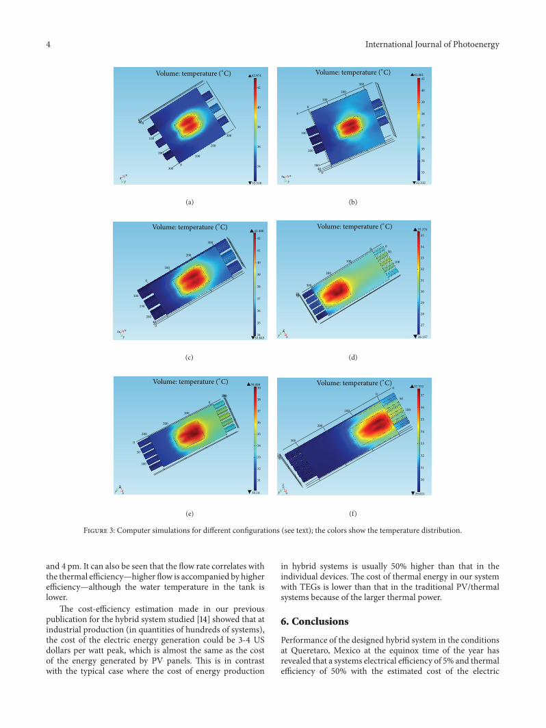
The heat exchanger was designed to be as simple aspossible a flat plate attached to the commercial pipes InFigure 3 the modeling results for several configurations arepresented changing parameters like hot plate location pipediameter piping array and welding material among othersIn this same figure simulations from Figure 3(a) to 3(c) arefor 1-inch-diameter and from Figure 3(d) to 3(f) are for 34-inch-diameter type K copper pipe according to ASTM B-88standard The red areas are the hottest and the blue ones thecoldest in accordance with the reference bar in the right sideof each model
After evaluating a wide range of configurations twooptions that best meet the conditions were selected andevaluated and the results are shown in Figure 4 One-inchtypeK cooper pipe [21] was used in (a) obtaining amaximumvalue of 424∘C in the center of the surface (red zone)34-inch type K pipe was chosen for case (b) leading to amaximum value of 394∘C distributed in a more uniform wayalong the center of the surface Thus option (b) was chosenfor the experiment
5 Experimental Results
The actual system studied is shown in the photograph inFigure 5 The positions of the thermocouples are indicatedby the red and blue points The red points also indicate thelocation of the ink injection used to give idea of the actualwater flow rate As can be seen in the image the thermoelec-tric assembly is illuminated by the concentration block
The results of the systemrsquos electrical and thermal charac-terization are presented in Figures 6 and 7 To estimate thesystemrsquos efficiency (both electrical and thermal) the intensityof solar radiation was taken as 950Wm which correspondsto the direct normal irradiance (DNI) in Queretaro Mexicoat 20∘ of northern latitude at the equinox time of the yearFirst the electric power generated by the system duringdaytime is shown in Figure 6 The measurements were takenwith a matched load so the data shown gives the maximumpower availableOne can see that the average powerwas 20Wthus producing 120Wh of electric energy between 10 am and4 pm (the total energy obtained during the day was 175Wh)These results correspond to a maximum electric efficiencyof the system of 5 which agrees well with the estimationsmade in [14] and with the results of modeling [16]
Figure 7 presents the thermal characteristics of the hybridsystemThe average hot water tank temperature was approxi-mately 45∘Cwhich is sufficient for domestic applicationsThevariations in the thermic efficiency 120578therm = (119876therm119876sol) times100 observed during the time of the experiment give inaverage of 50 which is higher than that an traditionalPVthermal systems The corresponding thermal power is200W giving the 12 kWh of energy in the 6 h between 10 am
4 International Journal of Photoenergy
119911
42974
42
40
38
36
34
32518
02040
0
100
200
300
0
100
200
300
119909
119910
Volume temperature (∘C)
(a)
119911 119909
119910
4106141
40
39
38
37
36
35
34
33
32332
02040300
200
100
0
0
100
200
300
Volume temperature (∘C)
(b)
119911 119909
119910
41
40
39
38
37
36
35
34
02040
0
100
200
300
100
150
200
42488
33843
42
Volume temperature (∘C)
(c)
119911
119909119910
01020
300
200
100
00
50
100
35376
35
34
33
32
31
30
29
28
27
26157
Volume temperature (∘C)
(d)
119911
119909119910
100
50
0
300
200
100
0
01020
3908939
38
37
36
35
34
33
32
31
3014
Volume temperature (∘C)
(e)
119911
119909119910
01020
300
200
100
0
0
50
100
37553
37
36
35
34
33
32
31
30
29021
Volume temperature (∘C)
(f)
Figure 3 Computer simulations for different configurations (see text) the colors show the temperature distribution
and 4 pm It can also be seen that the flow rate correlates withthe thermal efficiencymdashhigher flow is accompanied by higherefficiencymdashalthough the water temperature in the tank islower
The cost-efficiency estimation made in our previouspublication for the hybrid system studied [14] showed that atindustrial production (in quantities of hundreds of systems)the cost of the electric energy generation could be 3-4 USdollars per watt peak which is almost the same as the costof the energy generated by PV panels This is in contrastwith the typical case where the cost of energy production
in hybrid systems is usually 50 higher than that in theindividual devices The cost of thermal energy in our systemwith TEGs is lower than that in the traditional PVthermalsystems because of the larger thermal power
6 Conclusions
Performance of the designed hybrid system in the conditionsat Queretaro Mexico at the equinox time of the year hasrevealed that a systems electrical efficiency of 5 and thermalefficiency of 50 with the estimated cost of the electric
International Journal of Photoenergy 5
200
100
150
4239742
41
40
39
38
37
36
35
3433855
300
200
100
0119911119909
119910
Volume temperature (∘C)
(a)
0
50
100
300
200
100
0
0102039396
39
38
37
36
35
34
33
32
3130818
119911
119909119910
Volume temperature (∘C)
(b)
Figure 4 Computer simulations results for (a) 110158401015840 pipes and (b) 3410158401015840 pipes
Electricthermalgenerating unit
Concentrationblock
Figure 5 Photograph of the system
energy production are practically equal to those of thetraditional photovoltaicthermal systems Thus we concludethat the solar hybrid system with the concentrator and thethermoelectric generator even with the existing componentscan be considered as a reasonable alternative to the traditionalelectricthermal solar hybrid system Taking into account therapid progress in the development of newnanostructured andhighly efficient thermoelectric materials we can expect thatin the near future performance of the TEG-based systemscan surpass that of the traditional solar hybrid systems inparticular in the solar-rich regions having relatively lowlatitude
Nomenclature
119860119904 Effective flow area of the piping m119862119901 Specific heat capacity JKgsdot∘C119863 Piping diameter m119889ℎ Pressure head (thermal driving head) m
119891 Friction factor119892 Gravity msℎ Height mℎ119860 Energy added to the fluid Jℎ119888 Cold fluid column height mℎ119888 Average convection coefficient Wmsdot∘Cℎℎ Hot fluid column height mℎ119871 Friction head inside the piping mℎ119877 Energy removed to the fluid J119896119891 Friction coefficient119896 Thermal conductivity WmK119871 Piping length m119871eq Equivalent pipig length of theminor lossesm119871119905 Thermic inlet length m Mas flow KgsNu Average Nusselt number1199011 Inlet pressure Nm1199012 Outlet pressure Nm
Pr Prandtl number Heat flux W119876sun Solar heat input W119876out Bottoming heat transfer W119876therm Heat transfer to running water WRe Reynolds number119879119890 Outlet temperature in the fluid of the heating
pipe ∘C119879119894 Inlet temperature in the fluid of the heating
pipe ∘C119879119904 Inner surface temperature of the hot pipe ∘C119907 Flow velocity inside the piping ms1199071 Inlet velocity of the fluid ms1199072 Outlet velocity of the fluid ms1199111 Height at the inlet point m1199112 Height at the outlet point m120578therm Thermic efficiency120588 Fluid density kgm120588119888 Cold fluid density kgm120588ℎ Hot fluid density kgm120574 Specific weight of the fluid Nm120583 Dynamic viscosity Kgmsdots
6 International Journal of Photoenergy
10 11 12 13 14 15 1616
17
18
19
20
21
22
Electric power
Pow
er (W
)
Time (h)
(a)
110 120 130 140 150 160 170 18016
17
18
19
20
21
22
Electric power
Pow
er (W
)
Temperature difference (K)
(b)
Figure 6 Electric power generation as a function of time of day (a) and as a function of the temperature difference between the TEG plates(b)
10 11 12 13 14 15 1620
25
30
35
40
45
50
Mean tank temperature
Tem
pera
ture
(∘C)
Time (h)
(a)
10 11 12 13 14 15 160
10
20
30
40
50
60
70
80
90
100
Thermic efficiencyFlow rate
Time (h)
Ther
mic
effici
ency
()
8
10
12
14
16
18
Flow
rate
(gs
)
(b)
Figure 7 Hot water tank temperature (a) and calculated thermal efficiency of the system and the flow rate in the thermosiphon (b)
Conflict of Interests
Noneof the authors of the presentwork have direct or indirectfinancial relation with the commercial identity ldquoCOMSOLMultiphysics 42ardquo that might lead to a conflict of interests ofany kind for any of the authors
Acknowledgments
The authors are grateful to CONACYT for financial sup-port of the project and for the PhD scholarship of E AChavez-Urbiola They would also like to thank Dr MikeBoldrick of the US Peace Corps for his review of the paper
References
[1] E C Kern Jr and M C Russell ldquoCombined photovoltaic andthermal hybrid collector systemsrdquo inProceedings of the 13th ISESPhotovoltaic Specialists pp 1153ndash1115 Washington DC USAJune 1978
[2] P Raghuraman ldquoAnalytical predictions of liquid and air pho-tovoltaicthermal flat-plate collector performancerdquo Journal ofSolar Energy Engineering vol 103 no 4 pp 291ndash298 1981
[3] H PThomas S JHayter R LMartin and LK Pierce ldquoPV andPVHybrid products for buildingsrdquo in Proceedings of the 16thEuropean Photovoltaic Solar Energy Conference and Exhibitionvol 2 pp 1894ndash1897 Glasgow UK May 2000
International Journal of Photoenergy 7
[4] H A Zondag D W De Vries W G J Van Helden R J CVan Zolingen and A A Van Steenhoven ldquoThe thermal andelectrical yield of a PV-thermal collectorrdquo Solar Energy vol 72no 2 pp 113ndash128 2002
[5] J Aschaber C Hebling and J Luther ldquoRealistic modelling ofTPV systemsrdquo Semiconductor Science and Technology vol 18no 5 pp S158ndashS164 2003
[6] Y Tripanagnostopoulos ldquoAspects and improvements of hybridphotovoltaicthermal solar energy systemsrdquo Solar Energy vol81 no 9 pp 1117ndash1131 2007
[7] H A Zondag ldquoFlat-plate PV-Thermal collectors and systems areviewrdquo Renewable and Sustainable Energy Reviews vol 12 no4 pp 891ndash959 2008
[8] S Dubey and G N Tiwari ldquoThermal modeling of a combinedsystem of photovoltaic thermal (PVT) solar water heaterrdquo SolarEnergy vol 82 no 7 pp 602ndash612 2008
[9] A IbrahimM Y OthmanMH Ruslan SMat and K SopianldquoRecent advances in flat plate photovoltaicthermal (PVT)solar collectorsrdquoRenewable and Sustainable Energy Reviews vol15 no 1 pp 352ndash365 2011
[10] Y Vorobiev J Gonzalez-Hernandez P Vorobiev and L BulatldquoThermal-photovoltaic solar hybrid system for efficient solarenergy conversionrdquo Solar Energy vol 80 no 2 pp 170ndash1762006
[11] S A Omer and D G Infield ldquoDesign optimization of ther-moelectric devices for solar power generationrdquo Solar EnergyMaterials and Solar Cells vol 53 no 1-2 pp 67ndash82 1998
[12] P Li L Cai P Zhai X Tang Q Zhang and M Niino ldquoDesignof a concentration solar thermoelectric generatorrdquo Journal ofElectronic Materials vol 39 no 9 pp 1522ndash1530 2010
[13] D Kraemer L Hu A Muto X Chen G Chen and MChiesa ldquoPhotovoltaic-thermoelectric hybrid systems a generaloptimization methodologyrdquo Applied Physics Letters vol 92 no24 Article ID 243503 2008
[14] E A Chavez-Urbiola Y Vorobiev and L P Bulat ldquoSolar hybridsystems with thermoelectric generatorsrdquo Solar Energy vol 86no 1 pp 369ndash378 2012
[15] W G J H M V Sark ldquoFeasibility of photovoltaic-thermoelec-tric hybrid modulesrdquo Applied Energy vol 88 no 8 pp 2785ndash2790 2011
[16] D Kraemer K McEnaney M Chiesa and G Chen ldquoModelingand optimization of solar thermoelectric generators for terres-trial applicationsrdquo Solar Energy vol 86 no 5 pp 1338ndash13502012
[17] R Venkatasubramanian E Siivola T Colpitts and B OrsquoQuinnldquoThin-film thermoelectric devices with high room-temperaturefigures of meritrdquo Nature vol 413 no 6856 pp 597ndash602 2001
[18] A Tavkhelidze G Skhiladze A Bibilashvili et al ldquoThermionicconverter with quantum tunnelingrdquo in Proceedings of the IEEE22th International Conference on Thermoelectrics pp 435ndash438August 2002
[19] L P Bulat V T Bublik I A Drabkin et al ldquoBulk nanostruc-tured polycrystalline p-Bi-Sb-Te thermoelectrics obtained bymechanical activation method with hot pressingrdquo Journal ofElectronic Materials vol 39 no 9 pp 1650ndash1653 2010
[20] P Vorobiev and Y Vorobiev ldquoAutomatic Sun tracking solar elec-tric systems for applications on transportrdquo in Proceedings of 7thInternational Conference on Electrical Engineering ComputingScience and Automatic Control (CCE rsquo10) pp 66ndash70 ChiapasMexico September 2010
[21] R L Mott Applied Fluid Mechanics Macmillan New York NYUSA 4th edition 1994
Submit your manuscripts athttpwwwhindawicom
Hindawi Publishing Corporationhttpwwwhindawicom Volume 2014
Inorganic ChemistryInternational Journal of
Hindawi Publishing Corporation httpwwwhindawicom Volume 2014
International Journal ofPhotoenergy
Hindawi Publishing Corporationhttpwwwhindawicom Volume 2014
Carbohydrate Chemistry
International Journal of
Hindawi Publishing Corporationhttpwwwhindawicom Volume 2014
Journal of
Chemistry
Hindawi Publishing Corporationhttpwwwhindawicom Volume 2014
Advances in
Physical Chemistry
Hindawi Publishing Corporationhttpwwwhindawicom
Analytical Methods in Chemistry
Journal of
Volume 2014
Bioinorganic Chemistry and ApplicationsHindawi Publishing Corporationhttpwwwhindawicom Volume 2014
SpectroscopyInternational Journal of
Hindawi Publishing Corporationhttpwwwhindawicom Volume 2014
The Scientific World JournalHindawi Publishing Corporation httpwwwhindawicom Volume 2014
Medicinal ChemistryInternational Journal of
Hindawi Publishing Corporationhttpwwwhindawicom Volume 2014
Chromatography Research International
Hindawi Publishing Corporationhttpwwwhindawicom Volume 2014
Applied ChemistryJournal of
Hindawi Publishing Corporationhttpwwwhindawicom Volume 2014
Hindawi Publishing Corporationhttpwwwhindawicom Volume 2014
Theoretical ChemistryJournal of
Hindawi Publishing Corporationhttpwwwhindawicom Volume 2014
Journal of
Spectroscopy
Analytical ChemistryInternational Journal of
Hindawi Publishing Corporationhttpwwwhindawicom Volume 2014
Journal of
Hindawi Publishing Corporationhttpwwwhindawicom Volume 2014
Quantum Chemistry
Hindawi Publishing Corporationhttpwwwhindawicom Volume 2014
Organic Chemistry International
ElectrochemistryInternational Journal of
Hindawi Publishing Corporation httpwwwhindawicom Volume 2014
Hindawi Publishing Corporationhttpwwwhindawicom Volume 2014
CatalystsJournal of

2 International Journal of Photoenergy
Hot water output
Cold water inputWater
circulation
4
3
1
2
Figure 1 A schematic of the hybrid system
Hot plateCooling plate
TEG arrayWater flow
Figure 2 Thermoelectric generating (TEG) unit
(8 times 12 cm2) providing a concentration ratio (the number ofmirrors focused on the heating plate multiplied by the mirrorreflecting efficiency) of sim52 and considering a reflectionefficiency of 095 The mirrors were positioned in a paraboliccurve with the focal point over the heating plate of the TEGassembly the angle of the inclination of each mirror wascalculated to achieve this effect The block (mirror holder)was attached to the 2-axis sun-tracking system (see [20] fordetails) equipped with 2 pairs of radiation sensors positionedin such a way that the difference in photo response in eachcouple is zero if the mirror holder is orientated towardsthe sun giving the highest illumination of the absorberhot plate The difference in photo response increases withdisorientation (disorientation signal)This difference signal isapplied to a PIC16F877 microcontroller which monitors thesystem using two geared servomotors
The TEG array includes 6 generating elements of the typeTGM-127-14-25 based on Bi
2Te3(made by Kryotherm Saint
Petersburg Russia each element is 4 times 4 times 05 cm3)The elec-trical characteristics of the elements at different temperaturesof the operation were given in a previous publication [14]
3 Calculation of Thermosiphon Loop
For the thermosiphon solar water heaters the flow rate of thecirculating water is conventionally calculated by equating the
pressure head and the friction head Pressure head is causedby density gradients in the loop and the friction head iscaused by friction in the plumbing arrangement
The pressure head in the thermosiphon causes flow tooccur This flow in the collector is driven by the weight dif-ference between the hot water column in the return pipepassing through the collector and the cold fluid column inthe inlet pipe The temperature conditions are given by theinlet temperature of the fluid 119879
119894= 25∘C and the inner surface
temperature of the hot pipe 119879119904= 40∘C the density variations
in the water along the collector are assumed to be linear forthe calculations [21] The desired maximum temperature inthe cooling plate should be around 50∘C
Imagine an opened thermosiphon loop as a U-tubecontaining a fluid with one column filled with hot fluid andthe other with cold fluid A height difference 119889ℎ results dueto the density differences If instead ofU-tube one has a closedloop this 119889ℎ leads to a driving force that produces the flow inthe loop
The continuity equations under static equilibrium in caseof U-tube can be expressed by
ℎ119888120588119888= ℎℎ120588ℎ (1)
and the corresponding pressure head
119889ℎ = ℎℎminus ℎ119888 (2)
which is a function of the temperature and the total height ofthe columnsWe can rewrite (2) as a function of the cold- andhot-side densities and considering a total length 119871
119889ℎ = 119871(2
120588119888
120588119888+ 120588ℎ
minus 1) (3)
To determine the thermal driving forces it is necessaryto take into account the values of 119879
119894and 119879
119904 Using the desired
values of 119879119894= 25∘C and 119879
119904= 40∘C 119889ℎ = 251mm is ob-
tainedThe friction head flow rate and convective coefficient are
interrelated but they also depend on several physical param-eters that must be defined such as piping type materials andpipe length among others
Using the Bernoulli equation an energy conservationanalysis can be made For a pipe system [21] where 119901
1and
1199012are inlet and outlet pressures 119911
1and 119911
2are heights and
1199071and 1199072are the corresponding flow velocities the following
can be written in terms of energy
1199011
120574
+ 1199111+
1199072
1
2119892
+ ℎ119860minus ℎ119877minus ℎ119871=
1199012
120574
+ 1199112+
1199072
2
2119892
1199072 (4)
whereℎ119860is the added energyℎ
119877is the subtracted energyℎ
119871is
the energy loss (friction head) 119892 is the acceleration of gravityand 120574 is the specific weight of the fluid
On the other hand it is necessary to include the Darcyequation for friction head ℎ
119871
ℎ119871= 119891
119871
119863
1199072
2119892
(5)
International Journal of Photoenergy 3
where119871 is the piping length and119863 is its diameter that dependson the flow rate 119907 As the friction factor 119891 depends on theReynolds number Re for the laminar flow [21]
119891 =
64
Re=
64120583
119907119904119863120588
(6)
for a thermosiphon system the pressure head is equalized tofriction head causing the energy loss
119889ℎ = ℎ119871 (7)
As a consequence it is necessary to take into account theenergy losses due to friction (major losses due to friction andminor losses due to changes in the size and direction of theflow path) in the loop
The friction head can then be expressed for this case interms of the friction factor and the flow rate
ℎ119871= 15
1199072
119904
2119892
+ 3517
1199072
119904
2119892
119891 (8)
The first term corresponds to the sum of losses in the inletand outlet where it is common to use the estimation frictioncoefficient 119896
119891= 119891(119871eq119863) = 15 for systems of this kind [21]
Taking in consideration the laminar flow and equalizing thethermal driving head with the friction head we get
119889ℎ = 15
1199072
119904
2119892
+ 3517
119907119904
2119892
64120583
119863120588
(9)
Solving (9) for 119889ℎ = 251mm a flow rate of 119907119904=
00436ms is obtainedOnce the flow rate is defined the convective coefficient
can be calculated [21] For the laminar region in the circularpipe and the temperature of 25∘C the corresponding Nusseltaverage number is
Nu = 366 + 0065 (119863119871)Re Pr1 + [(119863119871)Re Pr]23
= 5051 119871119905lt 119871
(10)
For a thermal length 119871119905asymp 005 Re Pr119863 = 5047m the
condition 119871119905lt 119871 is satisfied and the convection coefficient
can be calculated as
ℎ119888=
Nu 119896119863
=
5051 sdot 0597 (WmK)001892m
= 15484 (Wm2K) (11)
Once ℎ119888and 119907119904are determined we can take them as initial
values for the design of the heat exchanger which starts withcomputer simulations
4 Design of the Heat Exchanger forElectricThermal Generating Unit
In order to determine the optimal configuration of the heatexchanger several configurations were proposed and evalu-ated using commercial finite elementmethod (FEM) software
(COMSOL Multiphysics 42a) For the flow rate the valueobtained earlier was used 119907
119904= 00436 (ms) The cooling
plate temperature must not exceed 50∘C and the hot platemust be around 200∘CThe solar power transformed into heatin the hot plate is around 200W in an area of 008 times 012m2in correspondence with the 2 times 3 array of TEG elements
The heat exchanger was designed to be as simple aspossible a flat plate attached to the commercial pipes InFigure 3 the modeling results for several configurations arepresented changing parameters like hot plate location pipediameter piping array and welding material among othersIn this same figure simulations from Figure 3(a) to 3(c) arefor 1-inch-diameter and from Figure 3(d) to 3(f) are for 34-inch-diameter type K copper pipe according to ASTM B-88standard The red areas are the hottest and the blue ones thecoldest in accordance with the reference bar in the right sideof each model
After evaluating a wide range of configurations twooptions that best meet the conditions were selected andevaluated and the results are shown in Figure 4 One-inchtypeK cooper pipe [21] was used in (a) obtaining amaximumvalue of 424∘C in the center of the surface (red zone)34-inch type K pipe was chosen for case (b) leading to amaximum value of 394∘C distributed in a more uniform wayalong the center of the surface Thus option (b) was chosenfor the experiment
5 Experimental Results
The actual system studied is shown in the photograph inFigure 5 The positions of the thermocouples are indicatedby the red and blue points The red points also indicate thelocation of the ink injection used to give idea of the actualwater flow rate As can be seen in the image the thermoelec-tric assembly is illuminated by the concentration block
The results of the systemrsquos electrical and thermal charac-terization are presented in Figures 6 and 7 To estimate thesystemrsquos efficiency (both electrical and thermal) the intensityof solar radiation was taken as 950Wm which correspondsto the direct normal irradiance (DNI) in Queretaro Mexicoat 20∘ of northern latitude at the equinox time of the yearFirst the electric power generated by the system duringdaytime is shown in Figure 6 The measurements were takenwith a matched load so the data shown gives the maximumpower availableOne can see that the average powerwas 20Wthus producing 120Wh of electric energy between 10 am and4 pm (the total energy obtained during the day was 175Wh)These results correspond to a maximum electric efficiencyof the system of 5 which agrees well with the estimationsmade in [14] and with the results of modeling [16]
Figure 7 presents the thermal characteristics of the hybridsystemThe average hot water tank temperature was approxi-mately 45∘Cwhich is sufficient for domestic applicationsThevariations in the thermic efficiency 120578therm = (119876therm119876sol) times100 observed during the time of the experiment give inaverage of 50 which is higher than that an traditionalPVthermal systems The corresponding thermal power is200W giving the 12 kWh of energy in the 6 h between 10 am
4 International Journal of Photoenergy
119911
42974
42
40
38
36
34
32518
02040
0
100
200
300
0
100
200
300
119909
119910
Volume temperature (∘C)
(a)
119911 119909
119910
4106141
40
39
38
37
36
35
34
33
32332
02040300
200
100
0
0
100
200
300
Volume temperature (∘C)
(b)
119911 119909
119910
41
40
39
38
37
36
35
34
02040
0
100
200
300
100
150
200
42488
33843
42
Volume temperature (∘C)
(c)
119911
119909119910
01020
300
200
100
00
50
100
35376
35
34
33
32
31
30
29
28
27
26157
Volume temperature (∘C)
(d)
119911
119909119910
100
50
0
300
200
100
0
01020
3908939
38
37
36
35
34
33
32
31
3014
Volume temperature (∘C)
(e)
119911
119909119910
01020
300
200
100
0
0
50
100
37553
37
36
35
34
33
32
31
30
29021
Volume temperature (∘C)
(f)
Figure 3 Computer simulations for different configurations (see text) the colors show the temperature distribution
and 4 pm It can also be seen that the flow rate correlates withthe thermal efficiencymdashhigher flow is accompanied by higherefficiencymdashalthough the water temperature in the tank islower
The cost-efficiency estimation made in our previouspublication for the hybrid system studied [14] showed that atindustrial production (in quantities of hundreds of systems)the cost of the electric energy generation could be 3-4 USdollars per watt peak which is almost the same as the costof the energy generated by PV panels This is in contrastwith the typical case where the cost of energy production
in hybrid systems is usually 50 higher than that in theindividual devices The cost of thermal energy in our systemwith TEGs is lower than that in the traditional PVthermalsystems because of the larger thermal power
6 Conclusions
Performance of the designed hybrid system in the conditionsat Queretaro Mexico at the equinox time of the year hasrevealed that a systems electrical efficiency of 5 and thermalefficiency of 50 with the estimated cost of the electric
International Journal of Photoenergy 5
200
100
150
4239742
41
40
39
38
37
36
35
3433855
300
200
100
0119911119909
119910
Volume temperature (∘C)
(a)
0
50
100
300
200
100
0
0102039396
39
38
37
36
35
34
33
32
3130818
119911
119909119910
Volume temperature (∘C)
(b)
Figure 4 Computer simulations results for (a) 110158401015840 pipes and (b) 3410158401015840 pipes
Electricthermalgenerating unit
Concentrationblock
Figure 5 Photograph of the system
energy production are practically equal to those of thetraditional photovoltaicthermal systems Thus we concludethat the solar hybrid system with the concentrator and thethermoelectric generator even with the existing componentscan be considered as a reasonable alternative to the traditionalelectricthermal solar hybrid system Taking into account therapid progress in the development of newnanostructured andhighly efficient thermoelectric materials we can expect thatin the near future performance of the TEG-based systemscan surpass that of the traditional solar hybrid systems inparticular in the solar-rich regions having relatively lowlatitude
Nomenclature
119860119904 Effective flow area of the piping m119862119901 Specific heat capacity JKgsdot∘C119863 Piping diameter m119889ℎ Pressure head (thermal driving head) m
119891 Friction factor119892 Gravity msℎ Height mℎ119860 Energy added to the fluid Jℎ119888 Cold fluid column height mℎ119888 Average convection coefficient Wmsdot∘Cℎℎ Hot fluid column height mℎ119871 Friction head inside the piping mℎ119877 Energy removed to the fluid J119896119891 Friction coefficient119896 Thermal conductivity WmK119871 Piping length m119871eq Equivalent pipig length of theminor lossesm119871119905 Thermic inlet length m Mas flow KgsNu Average Nusselt number1199011 Inlet pressure Nm1199012 Outlet pressure Nm
Pr Prandtl number Heat flux W119876sun Solar heat input W119876out Bottoming heat transfer W119876therm Heat transfer to running water WRe Reynolds number119879119890 Outlet temperature in the fluid of the heating
pipe ∘C119879119894 Inlet temperature in the fluid of the heating
pipe ∘C119879119904 Inner surface temperature of the hot pipe ∘C119907 Flow velocity inside the piping ms1199071 Inlet velocity of the fluid ms1199072 Outlet velocity of the fluid ms1199111 Height at the inlet point m1199112 Height at the outlet point m120578therm Thermic efficiency120588 Fluid density kgm120588119888 Cold fluid density kgm120588ℎ Hot fluid density kgm120574 Specific weight of the fluid Nm120583 Dynamic viscosity Kgmsdots
6 International Journal of Photoenergy
10 11 12 13 14 15 1616
17
18
19
20
21
22
Electric power
Pow
er (W
)
Time (h)
(a)
110 120 130 140 150 160 170 18016
17
18
19
20
21
22
Electric power
Pow
er (W
)
Temperature difference (K)
(b)
Figure 6 Electric power generation as a function of time of day (a) and as a function of the temperature difference between the TEG plates(b)
10 11 12 13 14 15 1620
25
30
35
40
45
50
Mean tank temperature
Tem
pera
ture
(∘C)
Time (h)
(a)
10 11 12 13 14 15 160
10
20
30
40
50
60
70
80
90
100
Thermic efficiencyFlow rate
Time (h)
Ther
mic
effici
ency
()
8
10
12
14
16
18
Flow
rate
(gs
)
(b)
Figure 7 Hot water tank temperature (a) and calculated thermal efficiency of the system and the flow rate in the thermosiphon (b)
Conflict of Interests
Noneof the authors of the presentwork have direct or indirectfinancial relation with the commercial identity ldquoCOMSOLMultiphysics 42ardquo that might lead to a conflict of interests ofany kind for any of the authors
Acknowledgments
The authors are grateful to CONACYT for financial sup-port of the project and for the PhD scholarship of E AChavez-Urbiola They would also like to thank Dr MikeBoldrick of the US Peace Corps for his review of the paper
References
[1] E C Kern Jr and M C Russell ldquoCombined photovoltaic andthermal hybrid collector systemsrdquo inProceedings of the 13th ISESPhotovoltaic Specialists pp 1153ndash1115 Washington DC USAJune 1978
[2] P Raghuraman ldquoAnalytical predictions of liquid and air pho-tovoltaicthermal flat-plate collector performancerdquo Journal ofSolar Energy Engineering vol 103 no 4 pp 291ndash298 1981
[3] H PThomas S JHayter R LMartin and LK Pierce ldquoPV andPVHybrid products for buildingsrdquo in Proceedings of the 16thEuropean Photovoltaic Solar Energy Conference and Exhibitionvol 2 pp 1894ndash1897 Glasgow UK May 2000
International Journal of Photoenergy 7
[4] H A Zondag D W De Vries W G J Van Helden R J CVan Zolingen and A A Van Steenhoven ldquoThe thermal andelectrical yield of a PV-thermal collectorrdquo Solar Energy vol 72no 2 pp 113ndash128 2002
[5] J Aschaber C Hebling and J Luther ldquoRealistic modelling ofTPV systemsrdquo Semiconductor Science and Technology vol 18no 5 pp S158ndashS164 2003
[6] Y Tripanagnostopoulos ldquoAspects and improvements of hybridphotovoltaicthermal solar energy systemsrdquo Solar Energy vol81 no 9 pp 1117ndash1131 2007
[7] H A Zondag ldquoFlat-plate PV-Thermal collectors and systems areviewrdquo Renewable and Sustainable Energy Reviews vol 12 no4 pp 891ndash959 2008
[8] S Dubey and G N Tiwari ldquoThermal modeling of a combinedsystem of photovoltaic thermal (PVT) solar water heaterrdquo SolarEnergy vol 82 no 7 pp 602ndash612 2008
[9] A IbrahimM Y OthmanMH Ruslan SMat and K SopianldquoRecent advances in flat plate photovoltaicthermal (PVT)solar collectorsrdquoRenewable and Sustainable Energy Reviews vol15 no 1 pp 352ndash365 2011
[10] Y Vorobiev J Gonzalez-Hernandez P Vorobiev and L BulatldquoThermal-photovoltaic solar hybrid system for efficient solarenergy conversionrdquo Solar Energy vol 80 no 2 pp 170ndash1762006
[11] S A Omer and D G Infield ldquoDesign optimization of ther-moelectric devices for solar power generationrdquo Solar EnergyMaterials and Solar Cells vol 53 no 1-2 pp 67ndash82 1998
[12] P Li L Cai P Zhai X Tang Q Zhang and M Niino ldquoDesignof a concentration solar thermoelectric generatorrdquo Journal ofElectronic Materials vol 39 no 9 pp 1522ndash1530 2010
[13] D Kraemer L Hu A Muto X Chen G Chen and MChiesa ldquoPhotovoltaic-thermoelectric hybrid systems a generaloptimization methodologyrdquo Applied Physics Letters vol 92 no24 Article ID 243503 2008
[14] E A Chavez-Urbiola Y Vorobiev and L P Bulat ldquoSolar hybridsystems with thermoelectric generatorsrdquo Solar Energy vol 86no 1 pp 369ndash378 2012
[15] W G J H M V Sark ldquoFeasibility of photovoltaic-thermoelec-tric hybrid modulesrdquo Applied Energy vol 88 no 8 pp 2785ndash2790 2011
[16] D Kraemer K McEnaney M Chiesa and G Chen ldquoModelingand optimization of solar thermoelectric generators for terres-trial applicationsrdquo Solar Energy vol 86 no 5 pp 1338ndash13502012
[17] R Venkatasubramanian E Siivola T Colpitts and B OrsquoQuinnldquoThin-film thermoelectric devices with high room-temperaturefigures of meritrdquo Nature vol 413 no 6856 pp 597ndash602 2001
[18] A Tavkhelidze G Skhiladze A Bibilashvili et al ldquoThermionicconverter with quantum tunnelingrdquo in Proceedings of the IEEE22th International Conference on Thermoelectrics pp 435ndash438August 2002
[19] L P Bulat V T Bublik I A Drabkin et al ldquoBulk nanostruc-tured polycrystalline p-Bi-Sb-Te thermoelectrics obtained bymechanical activation method with hot pressingrdquo Journal ofElectronic Materials vol 39 no 9 pp 1650ndash1653 2010
[20] P Vorobiev and Y Vorobiev ldquoAutomatic Sun tracking solar elec-tric systems for applications on transportrdquo in Proceedings of 7thInternational Conference on Electrical Engineering ComputingScience and Automatic Control (CCE rsquo10) pp 66ndash70 ChiapasMexico September 2010
[21] R L Mott Applied Fluid Mechanics Macmillan New York NYUSA 4th edition 1994
Submit your manuscripts athttpwwwhindawicom
Hindawi Publishing Corporationhttpwwwhindawicom Volume 2014
Inorganic ChemistryInternational Journal of
Hindawi Publishing Corporation httpwwwhindawicom Volume 2014
International Journal ofPhotoenergy
Hindawi Publishing Corporationhttpwwwhindawicom Volume 2014
Carbohydrate Chemistry
International Journal of
Hindawi Publishing Corporationhttpwwwhindawicom Volume 2014
Journal of
Chemistry
Hindawi Publishing Corporationhttpwwwhindawicom Volume 2014
Advances in
Physical Chemistry
Hindawi Publishing Corporationhttpwwwhindawicom
Analytical Methods in Chemistry
Journal of
Volume 2014
Bioinorganic Chemistry and ApplicationsHindawi Publishing Corporationhttpwwwhindawicom Volume 2014
SpectroscopyInternational Journal of
Hindawi Publishing Corporationhttpwwwhindawicom Volume 2014
The Scientific World JournalHindawi Publishing Corporation httpwwwhindawicom Volume 2014
Medicinal ChemistryInternational Journal of
Hindawi Publishing Corporationhttpwwwhindawicom Volume 2014
Chromatography Research International
Hindawi Publishing Corporationhttpwwwhindawicom Volume 2014
Applied ChemistryJournal of
Hindawi Publishing Corporationhttpwwwhindawicom Volume 2014
Hindawi Publishing Corporationhttpwwwhindawicom Volume 2014
Theoretical ChemistryJournal of
Hindawi Publishing Corporationhttpwwwhindawicom Volume 2014
Journal of
Spectroscopy
Analytical ChemistryInternational Journal of
Hindawi Publishing Corporationhttpwwwhindawicom Volume 2014
Journal of
Hindawi Publishing Corporationhttpwwwhindawicom Volume 2014
Quantum Chemistry
Hindawi Publishing Corporationhttpwwwhindawicom Volume 2014
Organic Chemistry International
ElectrochemistryInternational Journal of
Hindawi Publishing Corporation httpwwwhindawicom Volume 2014
Hindawi Publishing Corporationhttpwwwhindawicom Volume 2014
CatalystsJournal of