Embed Size (px)
Citation preview
Investigation of Seismic Performance of Steel Building Structures with Nonlinear Viscous Dampers Using Real-
time Hybrid Simulation
James Ricles, Ph.D., PEBruce G. Johnston Professor, Director NHERI@Lehigh,
Lehigh University, USA
Performance-Based Seismic Design of Structures International Workshop. Tongji Univ, Oct 12-15, 2017
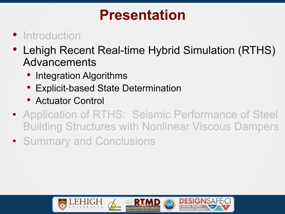
Presentation• Introduction• Lehigh Recent Real-time Hybrid Simulation (RTHS)
Advancements• Integration Algorithms• Explicit-based State Determination• Actuator Control
• Application of RTHS: Seismic Performance of Steel Building Structures with Nonlinear Viscous Dampers
• Summary and Conclusions
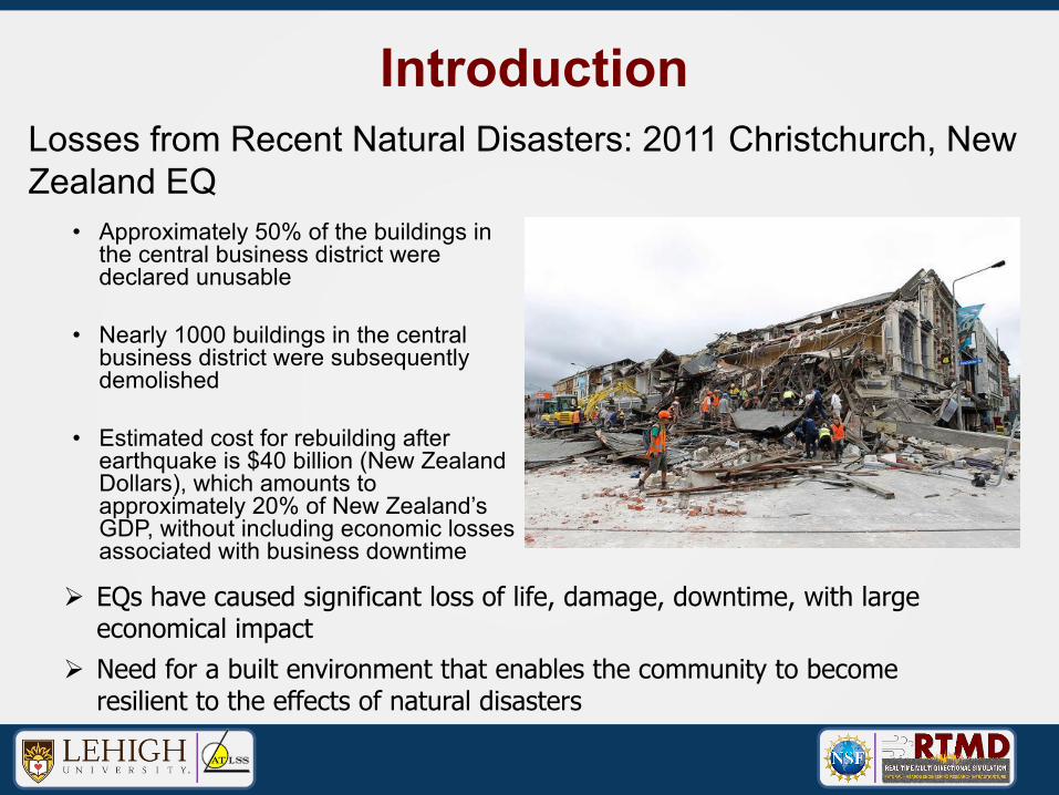
Losses from Recent Natural Disasters: 2011 Christchurch, New Zealand EQ
• Approximately 50% of the buildings in the central business district were declared unusable
• Nearly 1000 buildings in the central business district were subsequently demolished
• Estimated cost for rebuilding after earthquake is $40 billion (New Zealand Dollars), which amounts to approximately 20% of New Zealand’s GDP, without including economic losses associated with business downtime
Introduction
Ø EQs have caused significant loss of life, damage, downtime, with large economical impact
Ø Need for a built environment that enables the community to become resilient to the effects of natural disasters
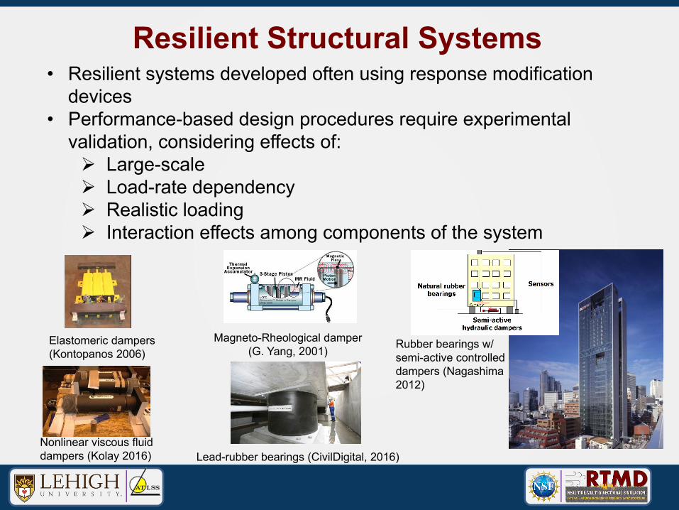
Resilient Structural Systems• Resilient systems developed often using response modification
devices• Performance-based design procedures require experimental
validation, considering effects of:Ø Large-scaleØ Load-rate dependencyØ Realistic loadingØ Interaction effects among components of the system
Elastomeric dampers (Kontopanos 2006)
Nonlinear viscous fluid dampers (Kolay 2016)
Magneto-Rheological damper (G. Yang, 2001)
Lead-rubber bearings (CivilDigital, 2016)
Rubber bearings w/ semi-active controlled dampers (Nagashima 2012)
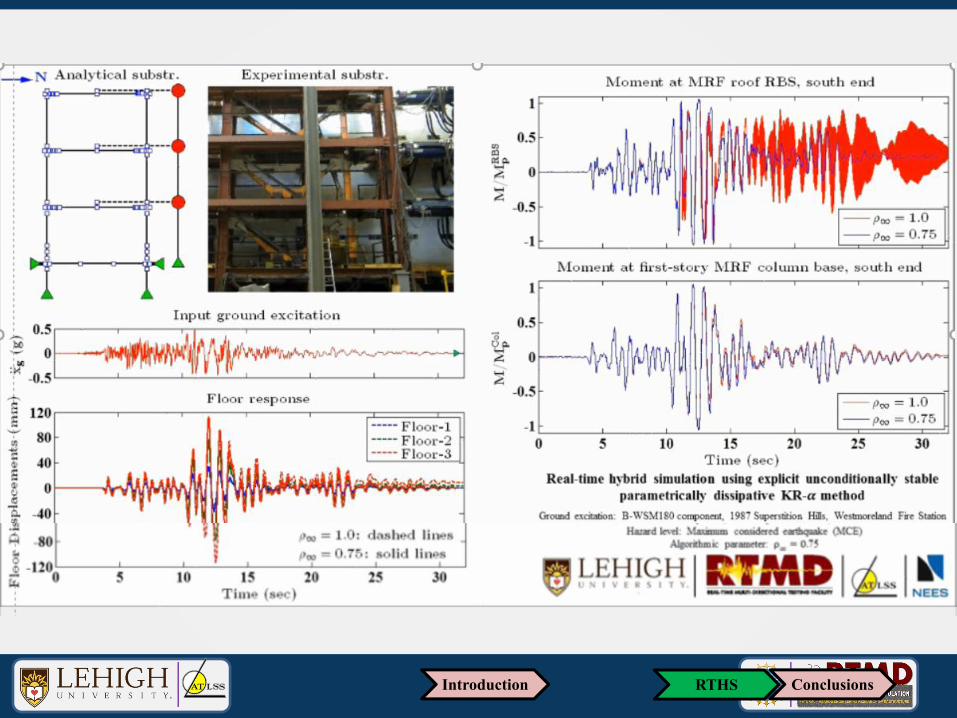
Introduction: RTHS Background
• Combines experimental and analytical substructures• Experimental substructure(s)
• Not well understood and modeled physically• Full scale component can be easily accommodated• Rate dependent devices (e.g., dampers, base-isolators) can be tested
• Analytical substructure(s)• Well understood and modeled numerically• Various substructures possible for a given experimental substructure• Damage can accumulate (not a problem) provided it can be modeled
• Advantages• Cost effective large-scale testing method• Comprehensive system response
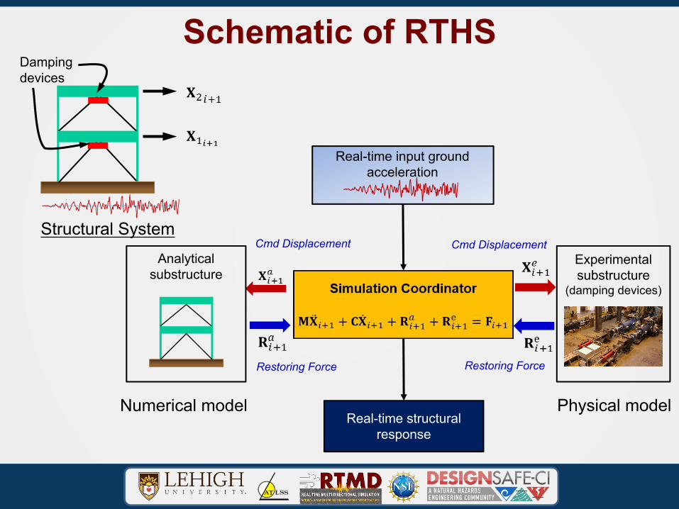
Schematic of RTHSDampingdevices
Structural System
Real-time structural response
Real-time input ground acceleration
Experimentalsubstructure
(damping devices)
Analyticalsubstructure
Cmd Displacement Cmd Displacement
Restoring Force Restoring Force
Numerical model Physical model
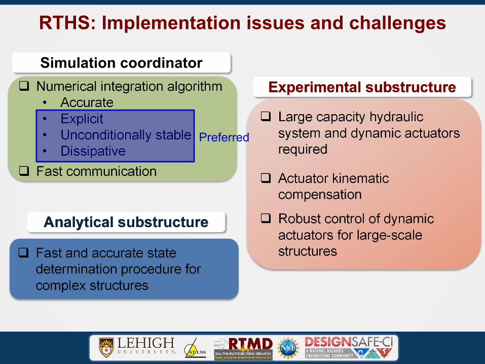
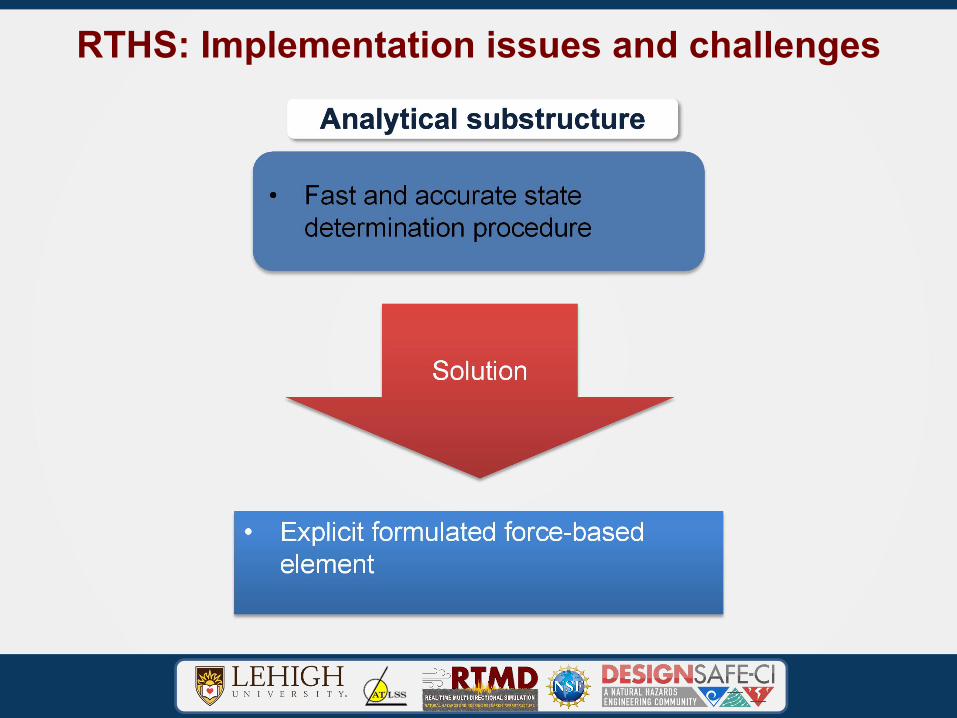
RTHS: Implementation issues and challenges
Analytical substructure
Experimental substructureSimulation coordinator
Preferred
Presentation• Introduction• Lehigh Recent Real-time Hybrid Simulation (RTHS)
Advancements• Integration Algorithms• Explicit-based State Determination• Actuator Control
• Application of RTHS: Seismic Performance of Steel Building Structures with Nonlinear Viscous Dampers
• Summary and Conclusions
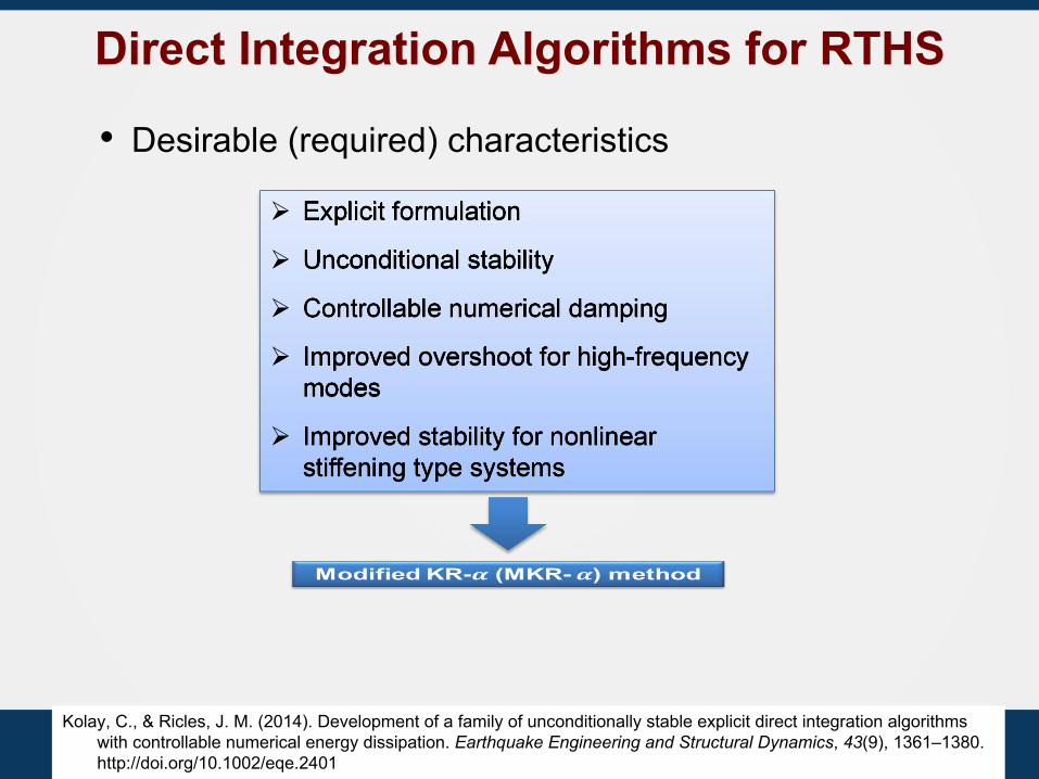
Direct Integration Algorithms for RTHS
Ø Explicit formulation
Ø Unconditional stability
Ø Controllable numerical damping
Ø Improved overshoot for high-frequency modes
Ø Improved stability for nonlinear stiffening type systems
• Desirable (required) characteristics
Kolay, C., & Ricles, J. M. (2014). Development of a family of unconditionally stable explicit direct integration algorithms with controllable numerical energy dissipation. Earthquake Engineering and Structural Dynamics, 43(9), 1361–1380. http://doi.org/10.1002/eqe.2401
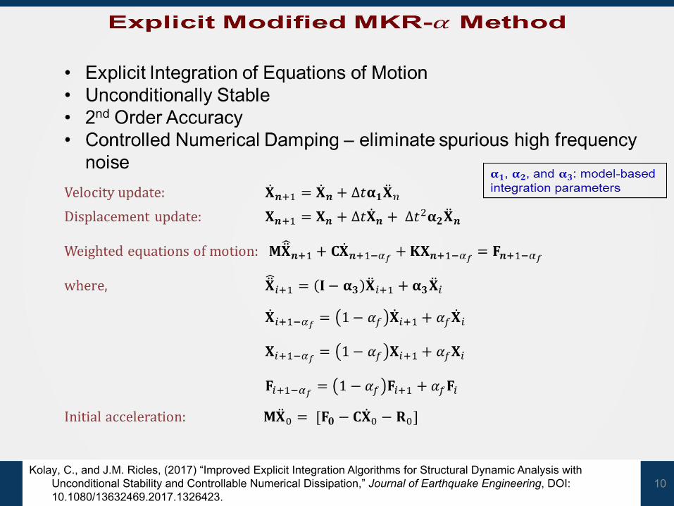
10Kolay, C., and J.M. Ricles, (2017) “Improved Explicit Integration Algorithms for Structural Dynamic Analysis with
Unconditional Stability and Controllable Numerical Dissipation,” Journal of Earthquake Engineering, DOI: 10.1080/13632469.2017.1326423.
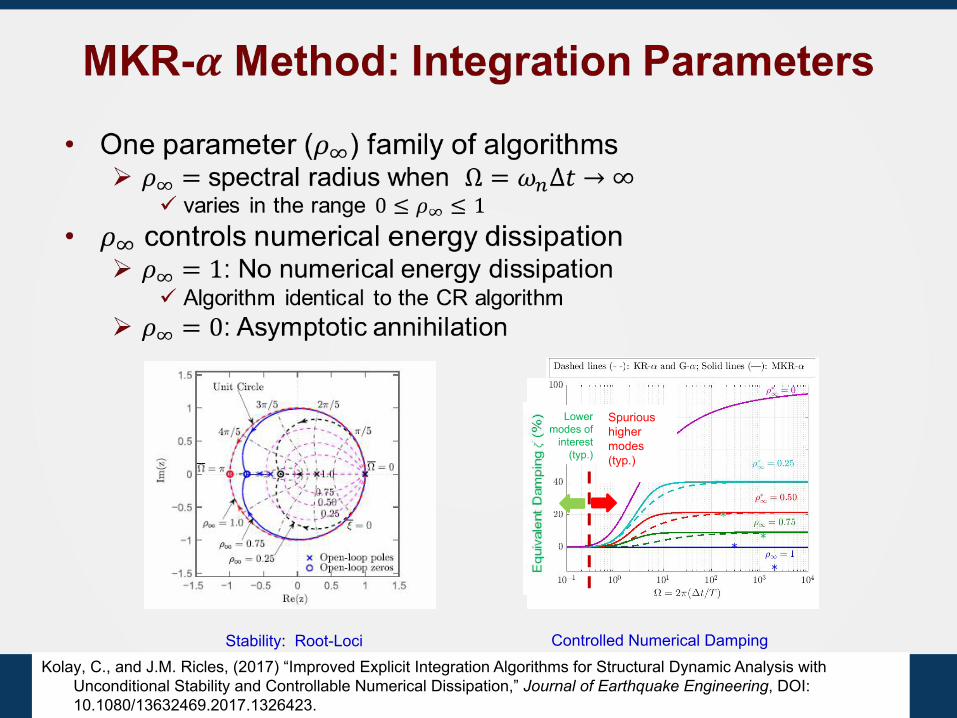
*
*
Spurious higher modes (typ.)
*
*
Lower modes of
interest (typ.)
Stability: Root-Loci Controlled Numerical DampingKolay, C., and J.M. Ricles, (2017) “Improved Explicit Integration Algorithms for Structural Dynamic Analysis with
Unconditional Stability and Controllable Numerical Dissipation,” Journal of Earthquake Engineering, DOI: 10.1080/13632469.2017.1326423.
12RTHSIntroduction Conclusions
13RTHSIntroduction Conclusions
RTHS: Implementation issues and challenges
Analytical substructure
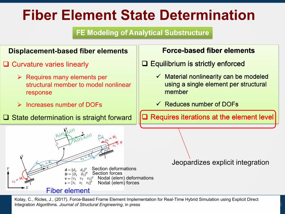
Fiber Element State Determination
Force-based fiber elements
q Equilibrium is strictly enforced
ü Material nonlinearity can be modeled using a single element per structural member
ü Reduces number of DOFs
q Requires iterations at the element level
15Kolay, C., Ricles, J., (2017). Force-Based Frame Element Implementation for Real-Time Hybrid Simulation using Explicit Direct Integration Algorithms. Journal of Structural Engineering, in press
Displacement-based fiber elements
q Curvature varies linearly
Ø Requires many elements per structural member to model nonlinear response
Ø Increases number of DOFs
q State determination is straight forward
Section deformationsSection forces
Nodal (elem) deformationsNodal (elem) forces
Fiber element
Jeopardizes explicit integration
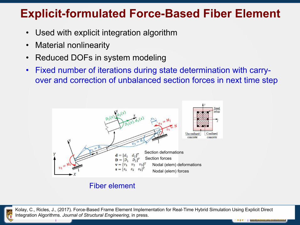
Explicit-formulated Force-Based Fiber Element
16Kolay, C., Ricles, J., (2017). Force-Based Frame Element Implementation for Real-Time Hybrid Simulation Using Explicit Direct Integration Algorithms. Journal of Structural Engineering, in press.
Section deformationsSection forces
Nodal (elem) deformationsNodal (elem) forces
Fiber element
• Used with explicit integration algorithm• Material nonlinearity• Reduced DOFs in system modeling• Fixed number of iterations during state determination with carry-
over and correction of unbalanced section forces in next time step
17
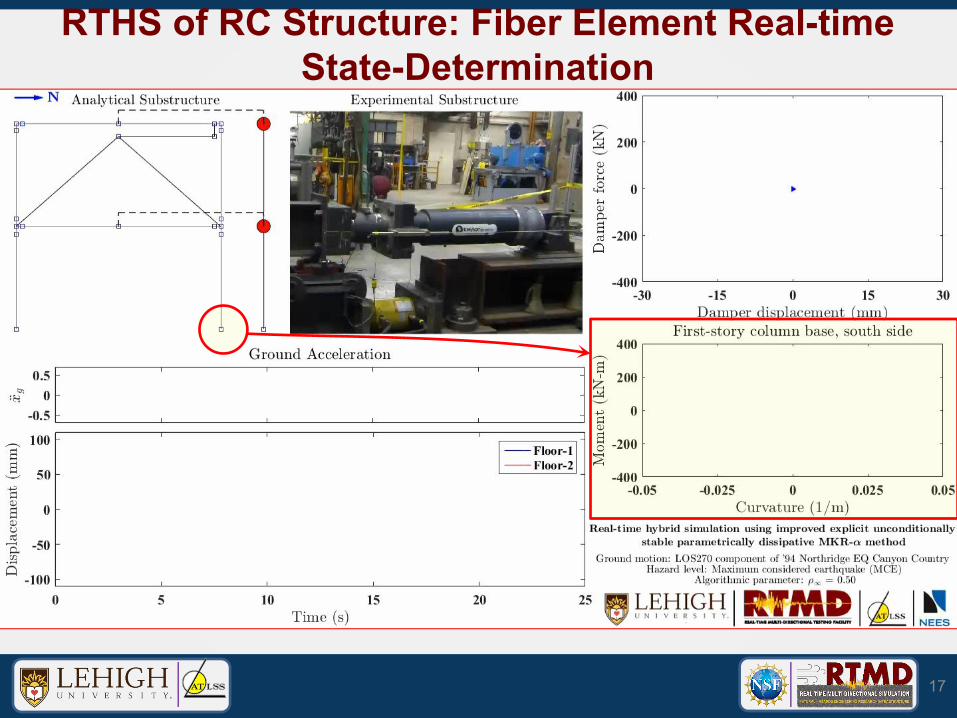
RTHS of RC Structure: Fiber Element Real-time State-Determination
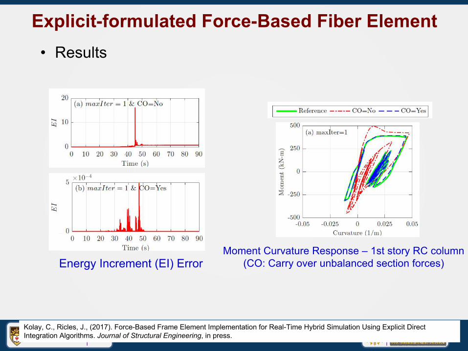
Explicit-formulated Force-Based Fiber Element
18Kolay, C., Ricles, J., (2017). Force-Based Frame Element Implementation for Real-Time Hybrid Simulation Using Explicit Direct Integration Algorithms. Journal of Structural Engineering, in press.
• Results
Energy Increment (EI) ErrorMoment Curvature Response – 1st story RC column
(CO: Carry over unbalanced section forces)
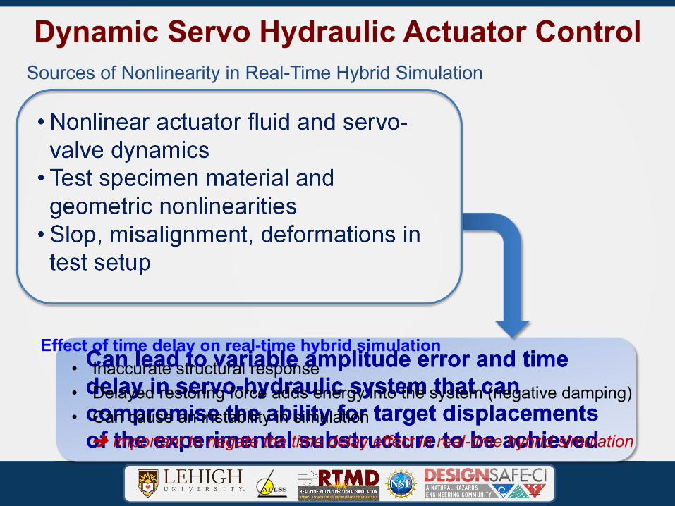
Dynamic Servo Hydraulic Actuator Control
• Nonlinear actuator fluid and servo-valve dynamics
• Test specimen material and geometric nonlinearities
• Slop, misalignment, deformations in test setup
Can lead to variable amplitude error and time delay in servo-hydraulic system that can compromise the ability for target displacements of the experimental substructure to be achieved
Effect of time delay on real-time hybrid simulation• Inaccurate structural response• Delayed restoring force adds energy into the system (negative damping)• Can cause an instability in simulation important to negate the time delay effect in real-time hybrid simulation
Sources of Nonlinearity in Real-Time Hybrid Simulation
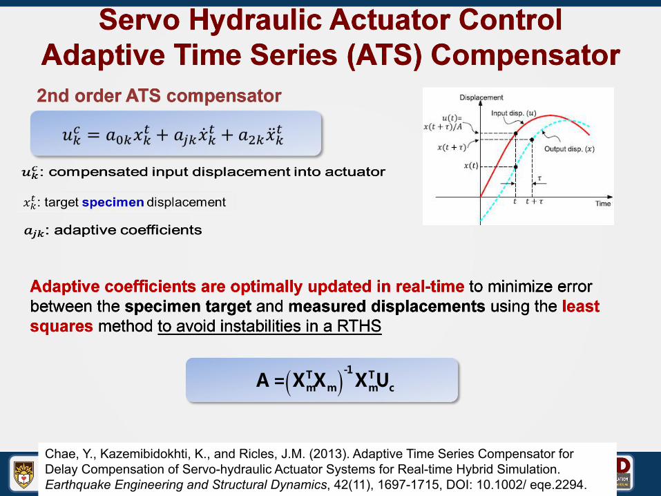
Servo Hydraulic Actuator ControlAdaptive Time Series (ATS) Compensator
Adaptive coefficients are optimally updated in real-time to minimize error between the specimen target and measured displacements using the least squares method to avoid instabilities in a RTHS
2nd order ATS compensator
A = XmTXm( )-1
XmTUc
Chae, Y., Kazemibidokhti, K., and Ricles, J.M. (2013). Adaptive Time Series Compensator for Delay Compensation of Servo-hydraulic Actuator Systems for Real-time Hybrid Simulation. Earthquake Engineering and Structural Dynamics, 42(11), 1697-1715, DOI: 10.1002/ eqe.2294.
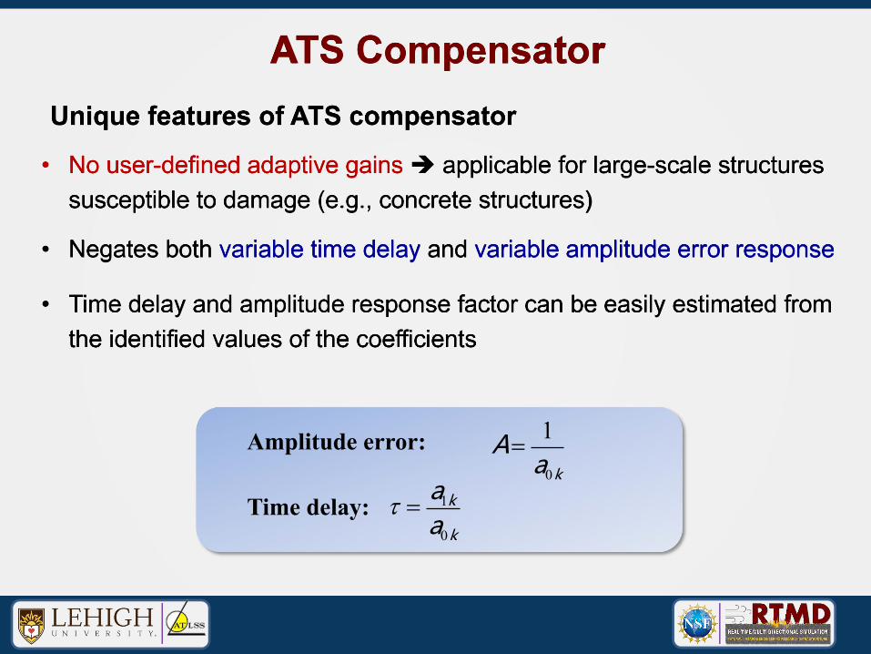
Unique features of ATS compensator
• No user-defined adaptive gains applicable for large-scale structures susceptible to damage (e.g., concrete structures)
ATS Compensator
• Negates both variable time delay and variable amplitude error response
• Time delay and amplitude response factor can be easily estimated from the identified values of the coefficients
Time delay:
Amplitude error: A= 1a0k
t = a1k
a0k
22RTHSIntroduction Conclusions
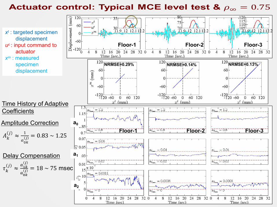
23
Floor-1 Floor-2 Floor-3
xt : targeted specimen displacement
uc : input command to actuator
xm : measured specimen displacement
NRMSE=0.13%NRMSE=0.14%NRMSE=0.29%
Amplitude Correction
Delay Compensation
Time History of Adaptive Coefficients
Floor-1 Floor-2 Floor-3a0
a1
a2
Presentation• Introduction• Lehigh Recent Real-time Hybrid Simulation (RTHS)
Advancements• Integration Algorithms• Explicit-based State Determination• Actuator Control
• Application of RTHS: Seismic Performance of Steel Building Structures with Nonlinear Viscous Dampers
• Summary and Conclusions
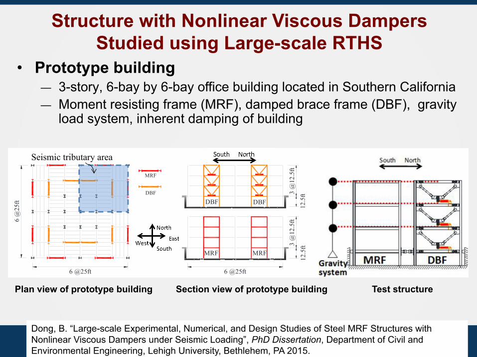
Structure with Nonlinear Viscous Dampers Studied using Large-scale RTHS
Plan view of prototype building Section view of prototype building
MRF
DBF
6 @25ft
6 @
25ft
6 @25ft
DBF DBF
MRF MRF
Plan view of 3-story prototype building Elevation of 3-story prototype building3
@12
.5ft
12.5
ft
3 @
12.5
ft
12.5
ft
North
East
NorthSouthSeismic tributary area
Test structure
• Prototype building — 3-story, 6-bay by 6-bay office building located in Southern California— Moment resisting frame (MRF), damped brace frame (DBF), gravity
load system, inherent damping of building
Dong, B. “Large-scale Experimental, Numerical, and Design Studies of Steel MRF Structures with Nonlinear Viscous Dampers under Seismic Loading”, PhD Dissertation, Department of Civil and Environmental Engineering, Lehigh University, Bethlehem, PA 2015.
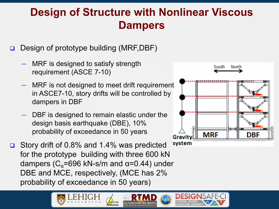
Design of Structure with Nonlinear Viscous Dampers
q Design of prototype building (MRF,DBF)
— MRF is designed to satisfy strength requirement (ASCE 7-10)
— MRF is not designed to meet drift requirement in ASCE7-10, story drifts will be controlled by dampers in DBF
— DBF is designed to remain elastic under the design basis earthquake (DBE), 10% probability of exceedance in 50 years
q Story drift of 0.8% and 1.4% was predicted for the prototype building with three 600 kN dampers (Cα=696 kN-s/m and α=0.44) under DBE and MCE, respectively, (MCE has 2% probability of exceedance in 50 years)
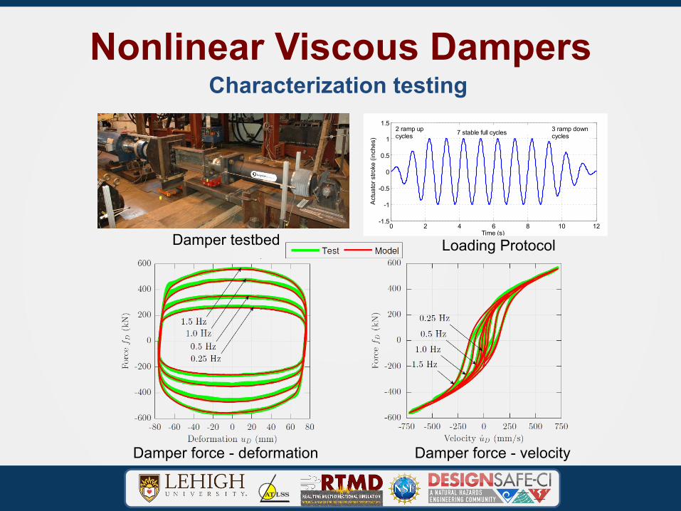
Nonlinear Viscous Dampers
Damper testbed
Characterization testing
Damper force - deformation Damper force - velocity
0 2 4 6 8 10 12-1.5
-1
-0.5
0
0.5
1
1.5
Time (s)
Act
uato
r stro
ke (i
nche
s)
3 ramp downcycles
2 ramp upcycles 7 stable full cycles
Loading Protocol
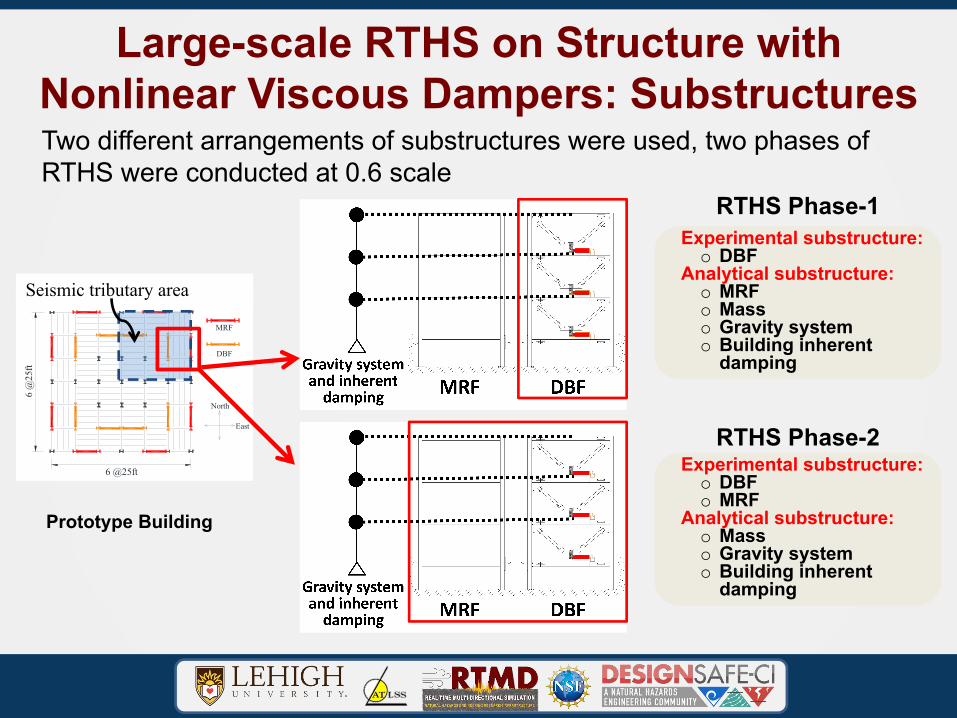
Large-scale RTHS on Structure with Nonlinear Viscous Dampers: SubstructuresTwo different arrangements of substructures were used, two phases of RTHS were conducted at 0.6 scale
RTHS Phase-1
Prototype Building
Experimental substructure:o DBF
Analytical substructure:o MRFo Masso Gravity systemo Building inherent
damping
Experimental substructure:o DBFo MRF
Analytical substructure:o Masso Gravity systemo Building inherent
damping
RTHS Phase-2
MRF
DBF
6 @25ft
6 @
25ft
6 @25ft
DBF DBF
MRF MRF
Plan view of 3-story prototype building Elevation of 3-story prototype building
3 @
12.5
ft12
.5ft
3 @
12.5
ft12
.5ft
North
East
NorthSouthSeismic tributary area
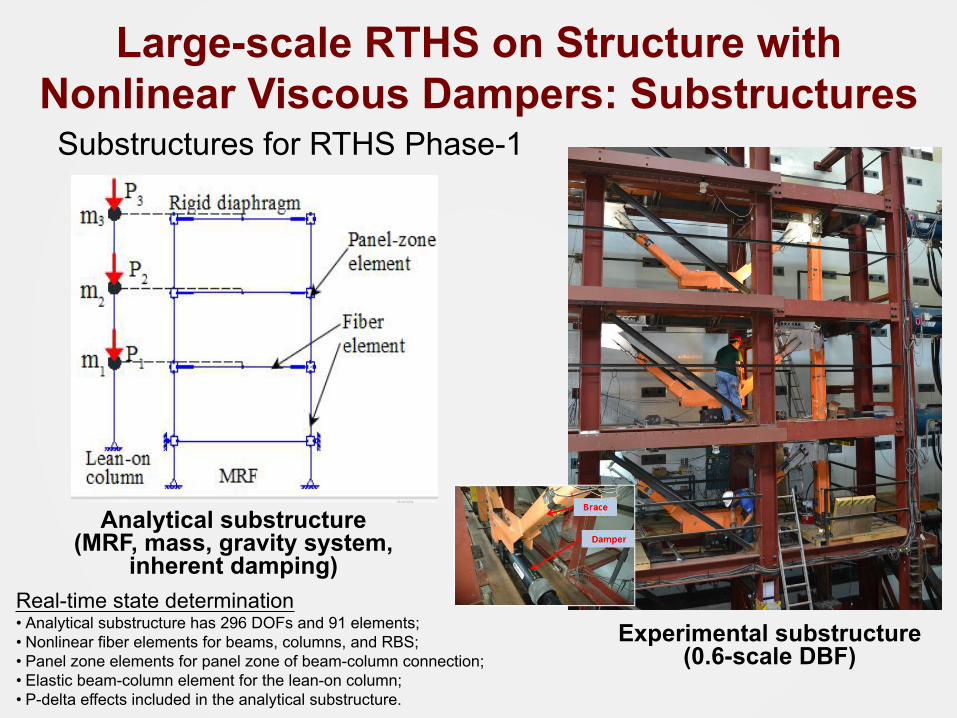
Substructures for RTHS Phase-1
Analytical substructure (MRF, mass, gravity system,
inherent damping)
Experimental substructure (0.6-scale DBF)
Real-time state determination• Analytical substructure has 296 DOFs and 91 elements;• Nonlinear fiber elements for beams, columns, and RBS;• Panel zone elements for panel zone of beam-column connection;• Elastic beam-column element for the lean-on column;• P-delta effects included in the analytical substructure.
Large-scale RTHS on Structure with Nonlinear Viscous Dampers: Substructures
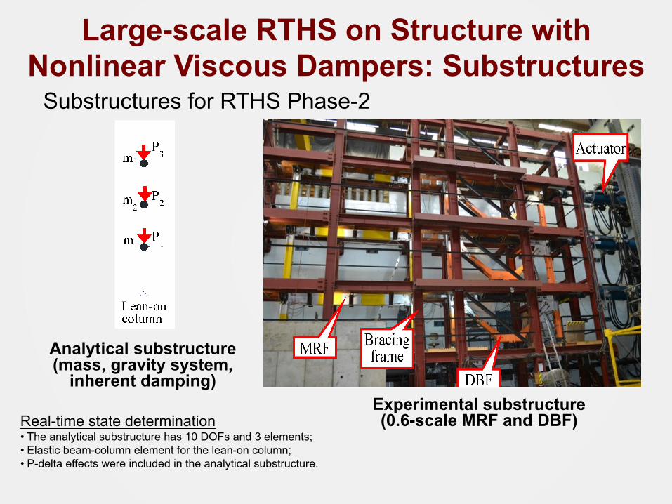
Substructures for RTHS Phase-2
Analytical substructure (mass, gravity system,
inherent damping)Experimental substructure (0.6-scale MRF and DBF)Real-time state determination
• The analytical substructure has 10 DOFs and 3 elements;• Elastic beam-column element for the lean-on column;• P-delta effects were included in the analytical substructure.
Large-scale RTHS on Structure with Nonlinear Viscous Dampers: Substructures
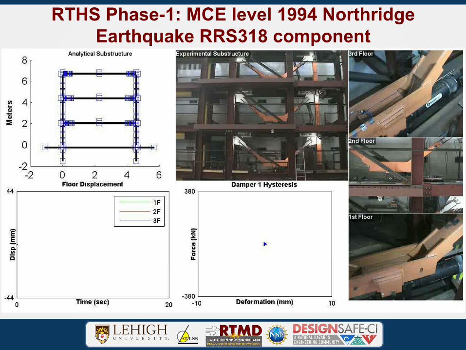
RTHS Phase-1: MCE level 1994 Northridge Earthquake RRS318 component
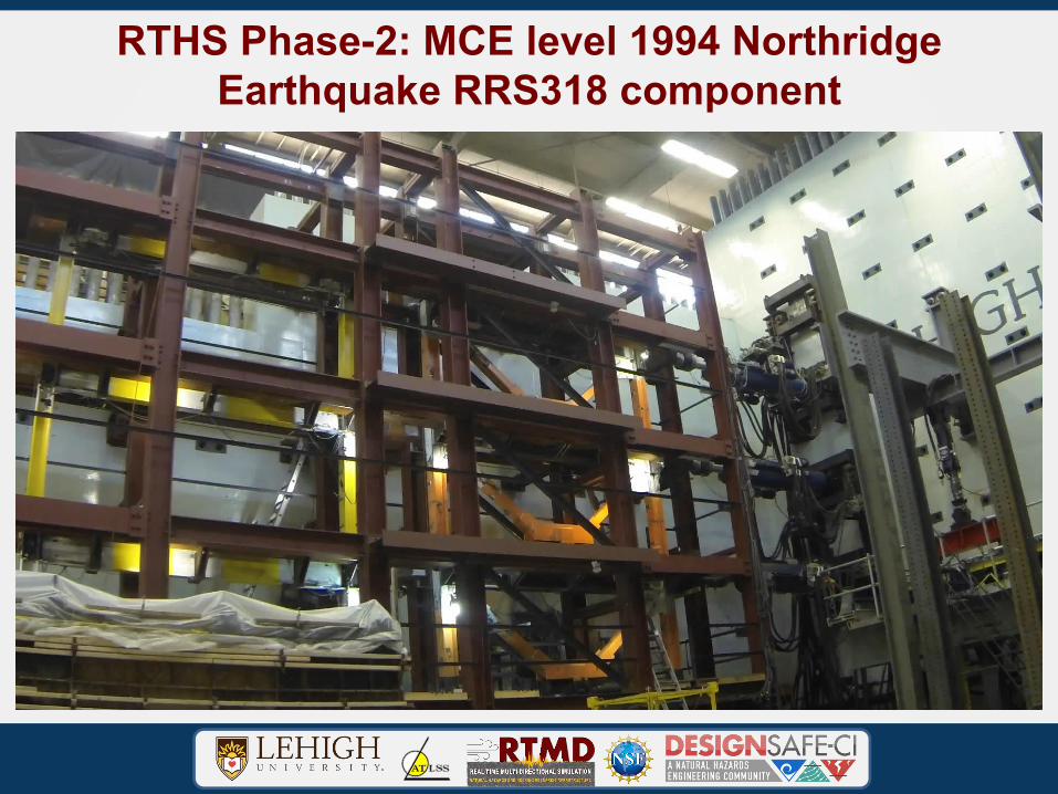
RTHS Phase-2: MCE level 1994 Northridge Earthquake RRS318 component
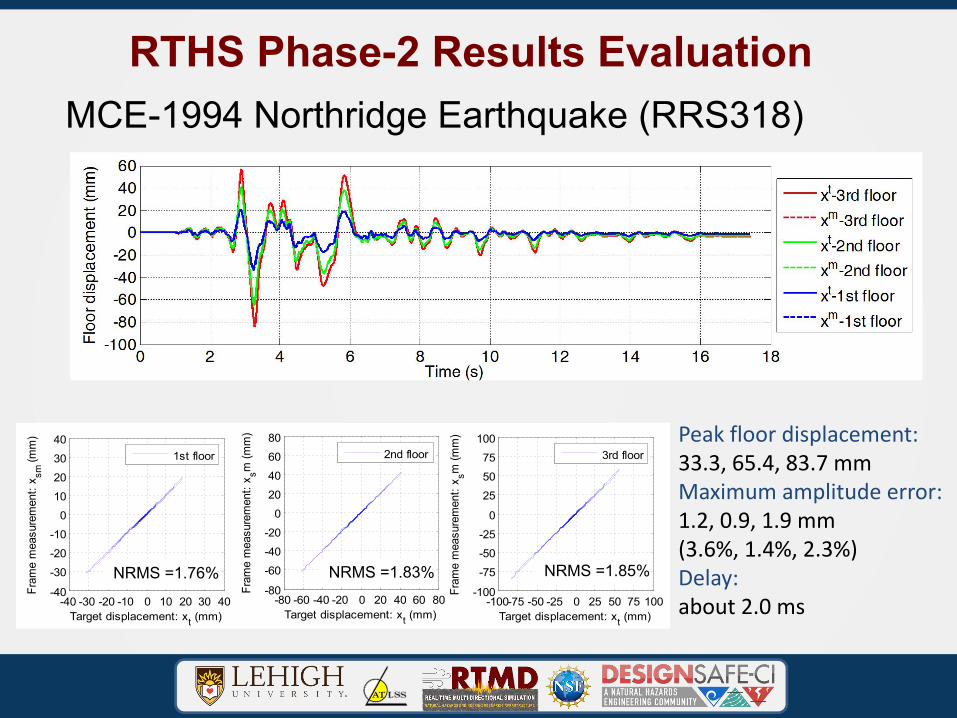
RTHS Phase-2 Results EvaluationMCE-1994 Northridge Earthquake (RRS318)
Peak floor displacement:33.3, 65.4, 83.7 mmMaximum amplitude error: 1.2, 0.9, 1.9 mm(3.6%, 1.4%, 2.3%)Delay: about 2.0 ms-40 -30 -20 -10 0 10 20 30 40
-40
-30-20-10
010203040
Target displacement: xt (mm)
Fram
e m
easu
rem
ent:
x sm (m
m)
1st floor
-80 -60 -40 -20 0 20 40 60 80-80
-60-40-20
020406080
Target displacement: xt (mm)
Fram
e m
easu
rem
ent:
x sm (m
m)
2nd floor
-100-75 -50 -25 0 25 50 75 100-100
-75-50-25
0
255075
100
Target displacement: xt (mm)
Fram
e m
easu
rem
ent:
x sm (m
m)
3rd floor
NRMS =1.76% NRMS =1.83% NRMS =1.85%
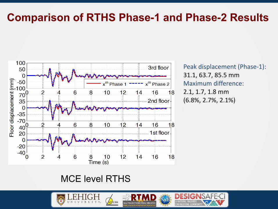
Comparison of RTHS Phase-1 and Phase-2 Results
Peak displacement (Phase-1):31.1, 63.7, 85.5 mmMaximum difference: 2.1, 1.7, 1.8 mm(6.8%, 2.7%, 2.1%)
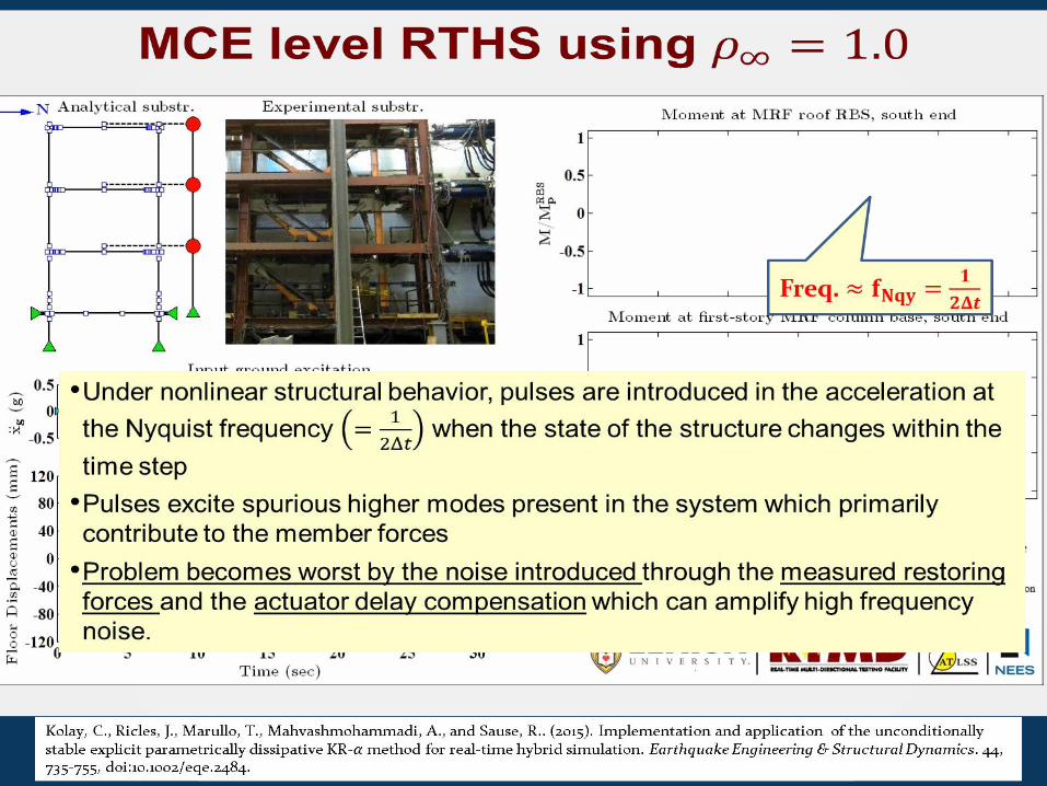
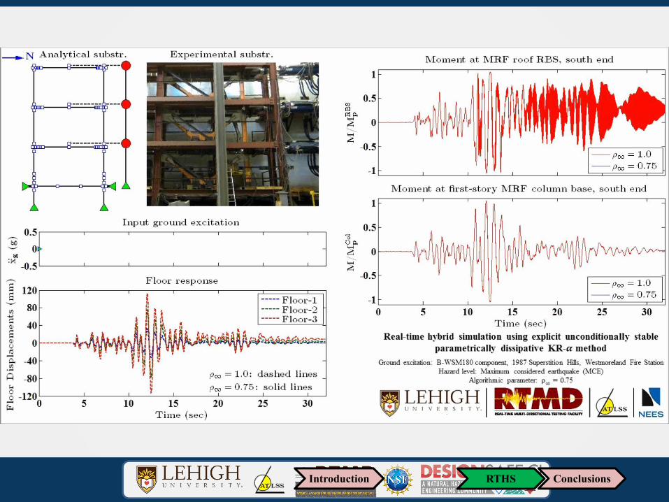
MCE level RTHS
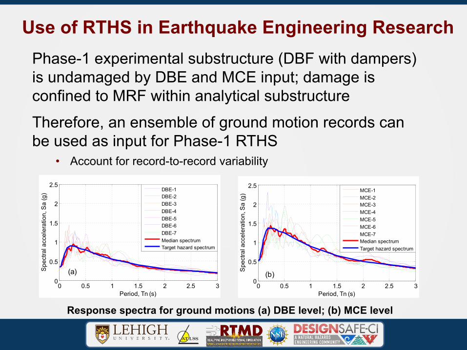
Use of RTHS in Earthquake Engineering ResearchPhase-1 experimental substructure (DBF with dampers) is undamaged by DBE and MCE input; damage is confined to MRF within analytical substructureTherefore, an ensemble of ground motion records can be used as input for Phase-1 RTHS
• Account for record-to-record variability
0 0.5 1 1.5 2 2.5 30
0.5
1
1.5
2
2.5
Period, Tn (s)
Spe
ctra
l acc
eler
atio
n, S
a (g
)
DBE-1DBE-2DBE-3DBE-4DBE-5DBE-6DBE-7Median spectrumTarget hazard spectrum
(a)
0 0.5 1 1.5 2 2.5 30
0.5
1
1.5
2
2.5
Period, Tn (s)
Spe
ctra
l acc
eler
atio
n, S
a (g
)
MCE-1MCE-2MCE-3MCE-4MCE-5MCE-6MCE-7Median spectrumTarget hazard spectrum
(b)
Response spectra for ground motions (a) DBE level; (b) MCE level
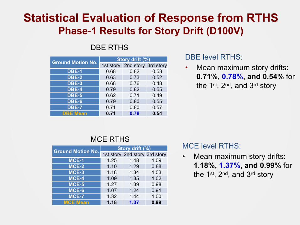
Statistical Evaluation of Response from RTHSPhase-1 Results for Story Drift (D100V)
DBE level RTHS:• Mean maximum story drifts:
0.71%, 0.78%, and 0.54% for the 1st, 2nd, and 3rd story
Ground Motion No. Story drift (%)1st story 2nd story 3rd story
DBE-1 0.68 0.82 0.53DBE-2 0.63 0.73 0.52DBE-3 0.68 0.76 0.48DBE-4 0.79 0.82 0.55DBE-5 0.62 0.71 0.49DBE-6 0.79 0.80 0.55DBE-7 0.71 0.80 0.57
DBE Mean 0.71 0.78 0.54
Ground Motion No. Story drift (%)1st story 2nd story 3rd story
MCE-1 1.25 1.48 1.09MCE-2 1.10 1.29 0.88MCE-3 1.18 1.34 1.03MCE-4 1.09 1.35 1.02MCE-5 1.27 1.39 0.98MCE-6 1.07 1.24 0.91MCE-7 1.32 1.44 1.00
MCE Mean 1.18 1.37 0.99
MCE level RTHS:• Mean maximum story drifts:
1.18%, 1.37%, and 0.99% for the 1st, 2nd, and 3rd story
DBE RTHS
MCE RTHS
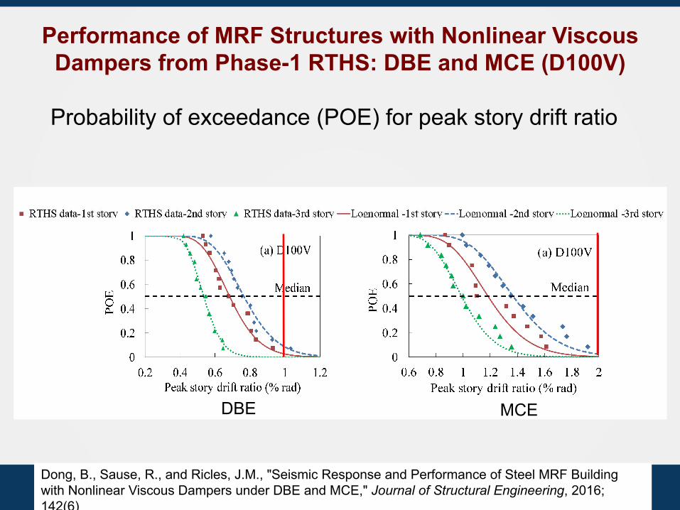
Probability of exceedance (POE) for peak story drift ratio
Performance of MRF Structures with Nonlinear Viscous Dampers from Phase-1 RTHS: DBE and MCE (D100V)
DBE MCE
Dong, B., Sause, R., and Ricles, J.M., "Seismic Response and Performance of Steel MRF Building with Nonlinear Viscous Dampers under DBE and MCE," Journal of Structural Engineering, 2016; 142(6)
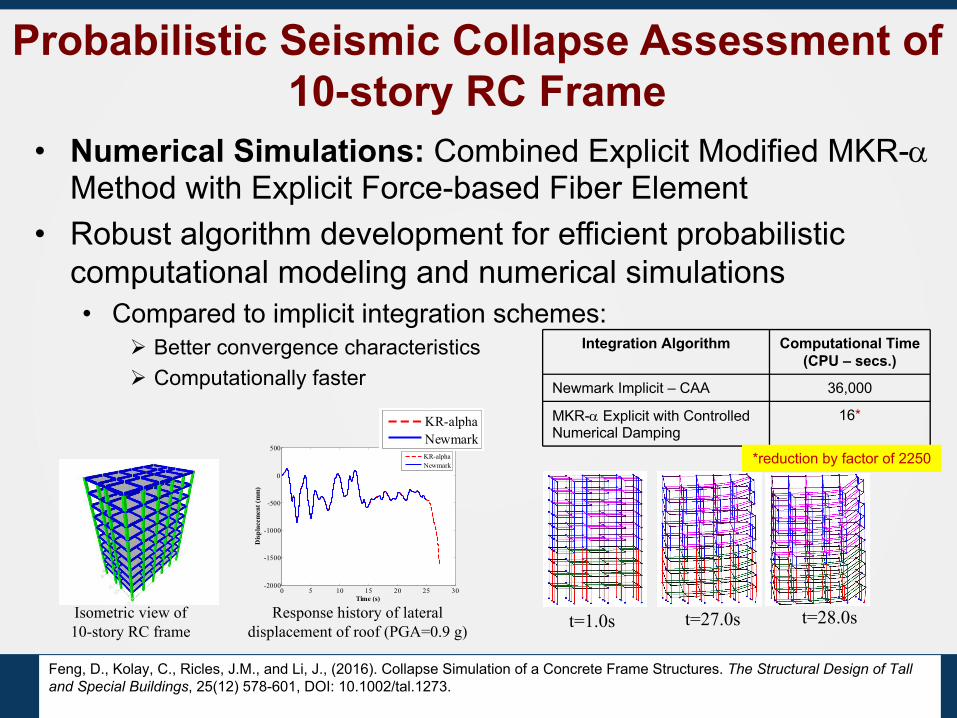
Probabilistic Seismic Collapse Assessment of 10-story RC Frame
• Numerical Simulations: Combined Explicit Modified MKR-a Method with Explicit Force-based Fiber Element
• Robust algorithm development for efficient probabilistic computational modeling and numerical simulations• Compared to implicit integration schemes:
Ø Better convergence characteristicsØ Computationally faster
t=1.0s t=27.0s t=28.0sIsometric view of 10-story RC frame
Integration Algorithm Computational Time (CPU – secs.)
Newmark Implicit – CAA 36,000
MKR-a Explicit with Controlled Numerical Damping
16*
*reduction by factor of 2250
Response history of lateral displacement of roof (PGA=0.9 g)
0 5 10 15 20 25 30-2000
-1500
-1000
-500
0
500
Time (s)
Disp
lace
men
t (m
m)
KR-alphaNewmark
0 5 10 15 20 25 30-2000
-1500
-1000
-500
0
500
Time (s)
Disp
lace
men
t (m
m)
KR-alphaNewmark
Feng, D., Kolay, C., Ricles, J.M., and Li, J., (2016). Collapse Simulation of a Concrete Frame Structures. The Structural Design of Tall and Special Buildings, 25(12) 578-601, DOI: 10.1002/tal.1273.
39
Summary and Conclusions• Advancements in real-time hybrid simulation were presented,
including integration algorithms, explicit-formulated force-based fiber element, and real-time adaptive servo-hydraulic actuator control.
• The application of real-time hybrid simulation to complex systems subject to earthquake hazards was illustrated, demonstrating these new advancements.
• The methodologies presented herein will enable real-time large-scale simulations of systems of higher complexities to be successfully achieved, leading to new discoveries and knowledge for hazard mitigation solutions, and innovative hazard-resistant structural concepts that promote resiliency.

Acknowledgements• Author would like to acknowledge the following Lehigh
University colleagues and former graduate students:• Professor Richard Sause• Professor Spencer Quiel• Thomas Marullo• Dr. Cheng Chen• Dr. Oya Mercan• Dr. Chinmoy Kolay• Dr. Yunbyeong Chae• Dr. Baiping Dong• Dr. Theodore Karavasilis• Safwan Al-Subaihawi
40
Acknowledgements• Research reported in this presentation was performed at the
NEES (NHERI) Lehigh Large-Scale Multi-Directional Hybrid Simulation Experimental Facility
• Supported by the National Science Foundation (NSF) under Awards CMS-0936610 and Pennsylvania Infrastructure Technology Alliance (Pennsylvania Department of Community and Economic Development)
• Financial support for the operation of the NEES and NHERI Lehigh Large-Scale Multi-Directional Hybrid Simulation Experimental Facility provided by NSF under Cooperative Agreement Nos. CMS-0402490 and CMMI-1520765, resp.
• Nonlinear viscous dampers provided by Taylor Devices Inc.
Thank you
*