Embed Size (px)
Citation preview

Journal of Materials Sciences and Applications
2018; 4(4): 58-67
http://www.aascit.org/journal/jmsa
ISSN: 2381-0998 (Print); ISSN: 2381-1005 (Online)
Investigation of Optical Properties of Zinc-Oxide Thin Films Deposited on Various Substrates: A Simulation Study
Sangita Das1, Sujan Kumar Das
2, *, Shyamal Ranjan Chakraborty
3, Arun Kumar Deb
3
1Department of Physics, Comilla University, Kotbari, Comilla, Bangladesh 2Department of Physics, Jahangirnagar University, Savar, Dhaka, Bangladesh 3Department of Physics, University of Chittagong, Chittagong, Bangladesh
Email address
*Corresponding author
Citation Sangita Das, Sujan Kumar Das, Shyamal Ranjan Chakraborty, Arun Kumar Deb. Investigation of Optical Properties of Zinc-Oxide Thin
Films Deposited on Various Substrates: A Simulation Study. Journal of Materials Sciences and Applications. Vol. 4, No. 4, 2018, pp. 58-67.
Received: January 27, 2018; Accepted: March 7, 2018; Published: June 7, 2018
Abstract: ZnO is an important II-VI semiconductor material for devices with possible applications such as piezo-electric
transducers, spin functional devices, gas sensors, transparent electronics in solar cell, UV light emitters, surface acoustic waves
and smart windows. In this study, the optical properties of ZnO thin films deposited on various substrates (quartz, sapphire,
KDP, fused silica, BK7 glass, BaF2, GeO2 and diamond) have been investigated. In order to investigate the optical properties, a
simulation program was developed. Famous computing language “MATLAB” was chosen as the coding language because of
its high ability to generate ideal graph. The optical properties (refractive index, transmittance, extinction coefficient, absorption
coefficient etc.) were studied as a function of wavelength in the range from 330nm to 1110nm. The refractive indices,
extinction coefficients, absorption coefficients, dielectric constants were also studied. The transmittance spectra of ZnO thin
films deposited on various substrates were investigated for different thicknesses (150nm, 400nm, 800nm) of the ZnO films.
The effects of interference on transmission spectra were also investigated. Fused silica and BaF2 are the best substrates for the
deposition of the ZnO thin film and give good reason for its applications in opto-electronic devices.
Keywords: Optoelectronics, Thin Film, ZnO, Simulation, Matlab
1. Introduction
Zinc Oxide (ZnO) is an important II-VI semiconductor
material, wide direct band gap semiconductor of around
3.4eV with high exciton binding energy (60 MeV) even at
room temperature [1, 2]. It also has several favorable
properties including good transparency, high electron
mobility, wide band gap and strong room temperature
luminescence. ZnO adopts the four-time coordinated wurtzite
phase in its ground state that belongs to the hexagonal hc
symmetry group and thus plays an important role in many
fundamental and technological applications [3]. One main
attractive feature of ZnO is the ability to band gap tuning via
divalent substitution on the cation side heterostructures [4].
Zinc Oxide (ZnO) is one of transparent conducting oxide
(TCO) materials whose thin films attract much interest
because of typical properties such as high chemical and
mechanical in hydrogen plasma, high optical transparency in
the visible and near infrared region [5–7]. Due to this
properties ZnO is a promising material for electronic or
optoelectronic applications such as solar cells (anti-reflecting
coating and transparent conducting materials), gas sensors,
liquid crystal displays, heat mirrors, surface acoustic devices
etc [8–10]. In addition to the traditional applications ZnO
thin films could also be used in integrated optics [11]. To
cram these optoelectronic devices it is obligatory to identify
the optical properties. In designing modern optoelectronic
and optical devices it is important to know the thickness,
refractive index and absorption coefficient as a function of
wavelength to predict the photoelectric behavior of a device
[12]. Besides, in order to develop ZnO thin films for
optoelectronic devices with superior performance it is also

Journal of Materials Sciences and Applications 2018; 4(4): 58-67 59
indispensable to expose the character and consequences of
substrates.
In 2013, N. Bouchenak Khelladi and N. E. Chabane Sari
studied the optical transmission properties of ZnO thin film
deposited on BK7 glass and Sapphire.
In this work the optical properties of ZnO thin film
deposited on about eight various substrates for different
thicknesses (150nm, 400nm, 800nm) were scrutinized using
a simulation program “Matlab”.
2. Materials &Methods
The brief model of the thin absorbent films on a
transparent thick substrate is shown in Figure 1. Here d and n
is the thickness and refractive index of the thin films
respectively. The substrate has a thickness of the several
orders of magnitude larger than ‘d’ and the refractive index is
‘S’. The index of surrounding air is defined as no=1. R1 is the
intensity of the reflected light on the interface between air
and film, and R2 is the reflection on the interface between the
film and substrate in middle. Reflection at the interface
between the substrate and air under substrate is not
considered here [13]. In this work quartz, sapphire, KDP,
fused silica, BK7 glass, BaF2, GeO2 and diamond were used
as substrates.
Figure 1. Model of the thin absorbent films on a transparent thick substrate [13].
Table 1. Fitting parameter by the method VASE of Sellmeier model for Zinc
Oxide [14].
A B C (nm) D E (nm)
2.0065 1.5748 ×10⁶ 1 ×10⁷ 1.5868 260.63
The Sellmeier equation for the refractive index, n, of ZnO
thin film as a function of wavelength is given by,
(1)
where A, B, C, D and E are fitting parameters, is the
wavelength of light (nm). Fitting parameters calculated at
different powers for different thickness, as deposit varies
significantly [1]. The Sellmeier coefficients of ZnO are given
in table 1.
From these fitting parameters the refractive index of ZnO
has been studied using the MATLAB programming software.
The refractive index of the substrate,
(2)
(3)
The Sellmeier coefficients of BK7-glass and other
substrates are given below in table 2 and 3.
Table 2. Sellmeier coefficients for BK7 glass [14].
Glass B1 B2 B3 C1 (nm2) C2 (nm2) C3 (nm2)
BK7 1.0396 2.3179×10⁻¹ 1.0104 6.0069×10³ 2.0017×10⁴ 1.0356×10⁸
Table 3. The Sellmeier coefficients of various substrates were given below [15].
Material A1 A2 A3 (nm) (nm) (nm)
Quartz, no 1.35400 0.010 0.9994 92.612 10700 9850
Sapphire 1.023798 1.058264 5.280792 61.4482 110.7 17926.56
KDP no 1.2540 0.0100 0.0992 96.46 6977.7 5984.8
Fused Silica 0.696749 0.408218 0.890815 69.066 115.662 9900.559
BaF2 0.63356 0.506762 3.8261 57.789 109.681 46386.42
GeO2 0.80686642 0.71815848 0.85416831 68.972606 153.96605 11841.931
Diamond 0.3306 4.3356 175 106
( )22
2
22
22
E
D
C
BAn
−+
−+=
λλ
λλλ
λ
( )3
2
2
3
2
2
2
2
1
2
2
12 1C
B
C
B
C
BS
−+
−+
−+=
λλ
λλ
λλλ
( )2
3
2
2
3
2
2
2
2
2
2
1
2
2
12 1λλ
λλλ
λλλ
λλ−
+−
+−
+=AAA
S
1λ 2λ3λ

60 Sangita Das et al.: Investigation of Optical Properties of Zinc-Oxide Thin Films Deposited on
Various Substrates: A Simulation Study
From these coefficients with the Matlab the refractive
indices of the substrates have been calculated.
The extinction coefficient of ZnO is given by the
following relation.
(4)
The Cauchy parameters of ZnO are given below in table 4.
Table 4. Cauchy parameter for zinc oxide [16].
Fk (nm-1) Gk (nm) Hk (nm)
0.0178 7327.1 337.87
With the help of equation (2.4) and Cauchy’s parameter, the
extinction co-efficient of ZnO thin film has been calculated.
After that the value of R1 and R2 has been calculated by
the following equation
(5)
(6)
The absorption coefficient of ZnO thin film is given by the
following equation [14]
(7)
The expression of the transmission of ZnO thin films
deposited on different substrates is given by [13],
(8)
(9)
In equation (8), T0 (λ) is considered to be the term of
transmission with no interference effect. The thicknesses of
the films were taken 150nm, 400nm, 800nm. For different
thicknesses of ZnO thin films deposited on various
substrates, the transmittances have been determined by
Matlab program. On the other hand, the transmission
spectrum can be divided into two terms. They are (1) non-
interference term (2) interference effect term.
The transmission of all ZnO thin film deposited on
different substrates have been determined from the following
formula [14],
(10)
where, &
From the equation (x), transmittance (without interference
effect), T0 for all ZnO thin films have been determined by
Matlab program for different thicknesses (150nm, 400nm,
800nm) of the film.
The transmittance (with interference effect) can be
expressed as [13],
(11)
From the equation (xi), transmittance (with interference
effect), T(λ)i for all ZnO thin films have been determined by
Matlab program for different thickness (150nm, 400nm,
800nm) of the film.
3. Results and Discussion
The optical properties of ZnO thin films were investigated
as a function of wavelength in the region of 330-1110nm.
3.1. Refractive Index
The variation of refractive indices with wavelength for
ZnO and different substrates are shown in Figure 2(a) to 2(i).
( )
−−
= λλλ11
kk
HG
k eFk
( )( ) 2
2
11
1
kn
knR
+++−=
( )( )2
2
2ns
nsR
+−=
λπα k4=
( ) ( ) ( )[ ]λδλλ cos2 210 RRTT −=
( ) πλ
πλδ +×= nd22
( )
=0
1ln
1
TB
A
dλα
snA 216= ( ) ( )231 snnB ++=
( ) ( ) ( )λλλ 0TTT i −=

Journal of Materials Sciences and Applications 2018; 4(4): 58-67 61
Figure 2. Variation of refractive index as a function of wavelength for (a) ZnO, (b) quartz, (c) sapphire, (d) KDP, (e) fused silica, (f) BK7-glass, (g) BaF2, (h)
GeO2, and (i) diamond.

62 Sangita Das et al.: Investigation of Optical Properties of Zinc-Oxide Thin Films Deposited on
Various Substrates: A Simulation Study
It was observed that the refractive indices decreased with
the increase in wavelength in the range from 330nm to
1110nm for all the substrates and ZnO thin films. It was
evident from graph that the value of refractive index went in
a single series of stages from one point to another point in the
higher wavelength region. At 330nm the refractive index is
1.57 for quartz, 1.80 for sapphire, 1.54 for KDP and BK7
glass, 1.48 for fused silica, 1.49 for BaF2, 1.66 for GeO2 and
2.5 for diamond. By comparing among all substrates it was
observed that diamond exhibits highest refractive index and
fused silica exhibits lowest refractive index.
3.2. Absorption Coefficient and Extinction
Coefficient
It was observed that absorption coefficient decreased with the
increase in wavelength as shown in Figure 3(a). From 330nm to
400nm wavelength region the absorption coefficient decreased
sharply and after that the value of absorption coefficient was
almost constant in the higher wavelength region.
Figure 3. Variation of (a) absorption coefficient and (b) extinction coefficient as a function of wavelength for ZnO thin film.
From the Figure 3(b) it was clear that the extinction
coefficient decreased with the increase in wavelength. The rise
and fall in the extinction coefficient is related to the absorption
of light. The value of extinction coefficient was high at UV
region and moved towards zero above 410nm which indicated
that there was tiny absorption in the visible region.
3.3. Transmission
Figure 4(a) to 4(h) shows the transmission spectra of ZnO
thin films of different thicknesses deposited on various
substrates.

Journal of Materials Sciences and Applications 2018; 4(4): 58-67 63
Figure 4. Transmission spectrum of ZnO thin film for different thickness deposited on (a) quartz substrate, (b) sapphire substrate, (c) KDP substrate, (d) fused
silica substrate, (e) BK7-glass substrate, (f) BaF2 substrate, (g) GeO2 substrate, and (h) diamond substrate.
It was observed from Figure 4(a) to 4(h) that the films
exhibit transmittance between 80% and 95% for wavelengths
greater than 550nm. The films were highly transparent in the
visible region and near infrared region but low in the
ultraviolet region. According to the value of transmittance the
observed transmission spectra can be divided into four
regions.
(i) Transparent region (500- 1110) nm: In the transparent
region the value of absorption was near to zero and the
transmittance was about 80% to 95%which was controlled by
the refractive indices of ZnO and substrates.
(ii) Weak absorption region (430-500) nm: The value of
absorption was small and the transmission started to decrease
in this region.
(iii) Medium absorption region (370-430) nm: In the
medium absorption region the value of absorption was large
and hence the transmission was low compared to absorption.
(iv) Strong absorption region (below 370 nm): For the
effect of absorption the transmission decreased severely in
this spectral region.
The rise and fall or peaks in the transmission spectra
occurred due to the effect of reflectance and interference of
the incident light. At the wavelength 610nm, quartz showed
transmittance about 92%, sapphire about 92%, KDP about
93%, BK7 glass about 92%, fused silica and BaF2 about
94%, GeO2 about 90% and diamond showed about 79%. By
comparing among these substrates it was found that fused
silica and BaF2 exhibited highest transmittance of about 94%
and diamond exhibited lowest transmittance of about 79% in
the visible region. It can be concluded that fused silica and
BaF2 are the best substrates for the deposition of ZnO thin
film.
3.4. Transmission Without Interference
Effect
The optical transmission spectra without interference
effect of the ZnO thin films of different thicknesses deposited
on various substrates as a function of wavelength ranging
between 330nm to 1110nm were represented from Figure
5(a) to 5(h). These figures showed excellent transmittance
across the visible and near infrared regions. The films
showed transmittance between 70% to 85% for wavelengths
greater than 450nm but low for wavelengths smaller than
400nm. In the spectra there were no peaks which were the
evidence of optical transmission spectra without interference
effect.

64 Sangita Das et al.: Investigation of Optical Properties of Zinc-Oxide Thin Films Deposited on
Various Substrates: A Simulation Study
Figure 5. Transmission spectrum without interference effect of ZnO thin film for different thicknesses deposited on (a) quartz substrate, (b) sapphire substrate,
(c) KDP substrate, (d) fused silica substrate, (e) BK7-glass substrate, (f) BaF2 substrate, (g) GeO2 substrate, and (h) diamond substrate.

Journal of Materials Sciences and Applications 2018; 4(4): 58-67 65
At wavelength greater than 590nm, the transmittance was
about 83% for quartz, 81% for sapphire, 83% for KDP and
BK7 glass, 84% for fused silica and BaF2, 82% for GeO2 and
73% for diamond. Fused silica and BaF2 exhibited highest
transmittance and diamond exhibited lowest transmittance in
the visible regionamong all these substrates.
3.5. Transmission with Interference Effect
The optical transmission spectra with interference effect of
the ZnO thin films of different thicknesses (150nm, 400nm,
800nm) deposited on various substrates as a function of
wavelength ranging between 330nm to 1110nm were
represented from Figure 6(a) to 6(h).
66 Sangita Das et al.: Investigation of Optical Properties of Zinc-Oxide Thin Films Deposited on
Various Substrates: A Simulation Study
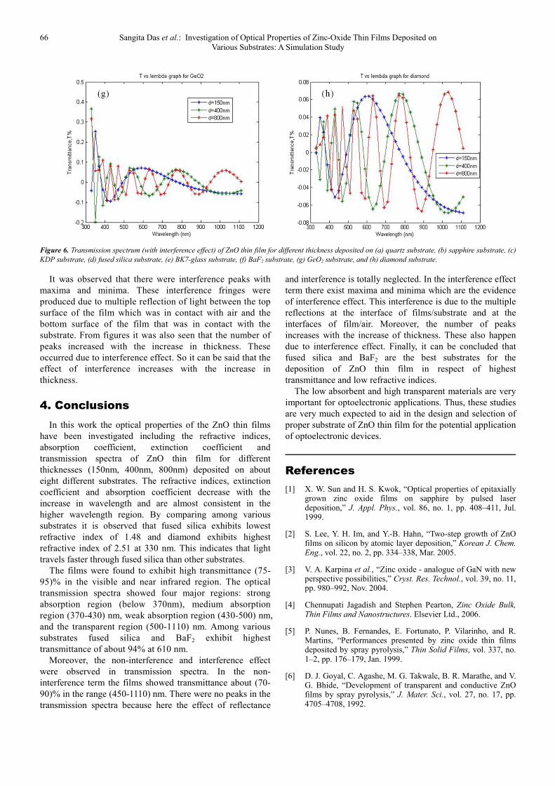
Figure 6. Transmission spectrum (with interference effect) of ZnO thin film for different thickness deposited on (a) quartz substrate, (b) sapphire substrate, (c)
KDP substrate, (d) fused silica substrate, (e) BK7-glass substrate, (f) BaF2 substrate, (g) GeO2 substrate, and (h) diamond substrate.
It was observed that there were interference peaks with
maxima and minima. These interference fringes were
produced due to multiple reflection of light between the top
surface of the film which was in contact with air and the
bottom surface of the film that was in contact with the
substrate. From figures it was also seen that the number of
peaks increased with the increase in thickness. These
occurred due to interference effect. So it can be said that the
effect of interference increases with the increase in
thickness.
4. Conclusions
In this work the optical properties of the ZnO thin films
have been investigated including the refractive indices,
absorption coefficient, extinction coefficient and
transmission spectra of ZnO thin film for different
thicknesses (150nm, 400nm, 800nm) deposited on about
eight different substrates. The refractive indices, extinction
coefficient and absorption coefficient decrease with the
increase in wavelength and are almost consistent in the
higher wavelength region. By comparing among various
substrates it is observed that fused silica exhibits lowest
refractive index of 1.48 and diamond exhibits highest
refractive index of 2.51 at 330 nm. This indicates that light
travels faster through fused silica than other substrates.
The films were found to exhibit high transmittance (75-
95)% in the visible and near infrared region. The optical
transmission spectra showed four major regions: strong
absorption region (below 370nm), medium absorption
region (370-430) nm, weak absorption region (430-500) nm,
and the transparent region (500-1110) nm. Among various
substrates fused silica and BaF2 exhibit highest
transmittance of about 94% at 610 nm.
Moreover, the non-interference and interference effect
were observed in transmission spectra. In the non-
interference term the films showed transmittance about (70-
90)% in the range (450-1110) nm. There were no peaks in the
transmission spectra because here the effect of reflectance
and interference is totally neglected. In the interference effect
term there exist maxima and minima which are the evidence
of interference effect. This interference is due to the multiple
reflections at the interface of films/substrate and at the
interfaces of film/air. Moreover, the number of peaks
increases with the increase of thickness. These also happen
due to interference effect. Finally, it can be concluded that
fused silica and BaF2 are the best substrates for the
deposition of ZnO thin film in respect of highest
transmittance and low refractive indices.
The low absorbent and high transparent materials are very
important for optoelectronic applications. Thus, these studies
are very much expected to aid in the design and selection of
proper substrate of ZnO thin film for the potential application
of optoelectronic devices.
References
[1] X. W. Sun and H. S. Kwok, “Optical properties of epitaxially grown zinc oxide films on sapphire by pulsed laser deposition,” J. Appl. Phys., vol. 86, no. 1, pp. 408–411, Jul. 1999.
[2] S. Lee, Y. H. Im, and Y.-B. Hahn, “Two-step growth of ZnO films on silicon by atomic layer deposition,” Korean J. Chem. Eng., vol. 22, no. 2, pp. 334–338, Mar. 2005.
[3] V. A. Karpina et al., “Zinc oxide - analogue of GaN with new perspective possibilities,” Cryst. Res. Technol., vol. 39, no. 11, pp. 980–992, Nov. 2004.
[4] Chennupati Jagadish and Stephen Pearton, Zinc Oxide Bulk, Thin Films and Nanostructures. Elsevier Ltd., 2006.
[5] P. Nunes, B. Fernandes, E. Fortunato, P. Vilarinho, and R. Martins, “Performances presented by zinc oxide thin films deposited by spray pyrolysis,” Thin Solid Films, vol. 337, no. 1–2, pp. 176–179, Jan. 1999.
[6] D. J. Goyal, C. Agashe, M. G. Takwale, B. R. Marathe, and V. G. Bhide, “Development of transparent and conductive ZnO films by spray pyrolysis,” J. Mater. Sci., vol. 27, no. 17, pp. 4705–4708, 1992.
Journal of Materials Sciences and Applications 2018; 4(4): 58-67 67
[7] A. Sanchez-Juarez, “Properties of fluorine-doped ZnO deposited onto glass by spray pyrolysis,” Sol. Energy Mater. Sol. Cells, vol. 52, no. 3–4, pp. 301–311, Apr. 1998.
[8] K. L. Chopra, S. Major, and D. K. Pandya, “Transparent conductors—A status review,” Thin Solid Films, vol. 102, no. 1, pp. 1–46, Apr. 1983.
[9] S. Bose and A. K. Barua, “The role of ZnO: Al films in the performance of amorphous-silicon based tandem solar cells,” J. Phys. D. Appl. Phys., vol. 32, no. 3, pp. 213–218, Feb. 1999.
[10] H. Kim et al., “Transparent conducting aluminum-doped zinc oxide thin films for organic light-emitting devices,” Appl. Phys. Lett., vol. 76, no. 3, pp. 259–261, Jan. 2000.
[11] G. Fang, D. Li, and B.-L. Yao, “Fabrication and vacuum annealing of transparent conductive AZO thin films prepared by DC magnetron sputtering,” Vacuum, vol. 68, no. 4, pp. 363–372, Dec. 2002.
[12] W. S. HU et al., “OPTICAL PROPERTIES OF PULSED LASER DEPOSITED ZnO THIN FILMS,” J. Phys. Chem. Solids, vol. 58, no. 6, pp. 853–857, Jun. 1997.
[13] W. Ming-Dong et al., “Determination of Thickness and Optical Constants of ZnO Thin Films Prepared by Filtered Cathode Vacuum Arc Deposition,” Chinese Phys. Lett., vol. 25, no. 2, pp. 743–746, Feb. 2008.
[14] N. B. Khelladi, “Simulation Study of Optical Transmission Properties of ZnO Thin Film Deposited on Dif-ferent Substrates,” Am. J. Opt. Photonics, vol. 1, no. 1, p. 1, 2013.
[15] J Singh, Optical Properties of Condensed Matter and Applications. Chichester, UK: John Wiley & Sons, Ltd, 2006.
[16] A. Ahmad and A. Alsaad, “Optical properties of ZnO related to the dc sputtering power,” Eur. Phys. J. B, vol. 52, no. 1, pp. 41–46, Jul. 2006.