Embed Size (px)
Citation preview

Vol. 129 (2016) ACTA PHYSICA POLONICA A No. 3
Investigation of New Algorithms for Estimation of Lossesin Microwave Devices Based on a Waveguide
or a Meander LineD. Plonis∗, A. Katkevičius, V. Mališauskas, A. Serackis and D. Matuzevičius
Vilnius Gediminas Technical University, Department of Electronic System,Naugarduko Str. 41-413, LT-03227, Vilnius, Lithuania
(Received November 19, 2015; in final form February 19, 2016)The aim of this paper was to introduce the estimation of the losses in the prototypes of the microwave devices.
We proposed in this paper two algorithms: an algorithm for evaluation of losses in the microwave devices based ona waveguide and an algorithm for evaluation of losses in the microwave devices based on a meander line. In orderto verify the results of losses evaluation for the waveguide-based device, we have used the electrodynamic modelof the open cylindrical gyrotropic waveguide with one anisotropic dielectric layer and the electrodynamic modelof the open cylindrical gyrotropic waveguide with two dielectric layers. In order to verify the results of lossesevaluation for the meander line-based device, we have used the model of the meander line with asymmetricalperiodical inhomogeneity. The comparison of the losses evaluation results received by the algorithms proposed inthis paper and the results received by application of the commercial software together with the alternative methodsconfirmed that the proposed algorithms produced correct results.
DOI: 10.12693/APhysPolA.129.414PACS/topics: 84.40.Az
1. Introduction
Waveguides and meander lines are widely used in de-sign of travelling-wave tubes, delay lines, phase modu-lators or converters, transmitters and other microwavedevices [1–5]. The methods for microwave device design,models and properties of various types of waveguides andmeander line based systems have been already analysedin the textbooks [5], scientific papers [6–8] and mono-graphs [9]. However, the design of new microwave de-vices, based on a new combination of the waveguide ma-terials and the design of microwave devices based on thenew shape of the meander line requires additional in-vestigation of the losses received in the newly designedsystem.
In order to estimate the losses in the newly designedmicrowave device, usually the simplified model of the de-vice is prototyped and used in the experimental tests.Although, frequently the ideal models of microwave sys-tems are considered disregarding the attenuation causedby the material used in the design of the device.
The gyrotropic waveguides are usually used to build apolarizer based on a Faraday effect. Erickson discussedan example of such polarizer, which was designed to workin 74–110 GHz frequency range [10]. In addition, wemay find axially magnetized cylindrical phase shifters,investigated by Iqbal and Gibson, which are based on thesemiconductor waveguides [11, 12]. However, the differ-ential phase shift received for these microwave devices is
∗corresponding author; e-mail: [email protected]
only 90 degrees and given papers lacks the more detailedanalysis of the frequency characteristics for the proposedphase shifters. Iqbal and Gibson presented only the anal-ysis of the TE11 mode propagation in the proposed phaseshifter model. Moreover, no analysis of the attenuationwas given for these phase shifters.
It is already known that the characteristics of de-vices designed using gyroelectric (semiconductor) mate-rials can be controlled by changing the temperature, thelongitudinal and axial magnetic flux density, the densityof the free carriers and γ-rays. It is also known that thehigh density of electrons in the material increases theattenuation of electromagnetic wave in the waveguides(also called magneto-active waveguides). These featureslimits the application of the given materials for the trans-mission of the EM wave [9, 13].
In order to design a waveguide based on a dielectric-metamaterial, Huang introduced the new models ofwaveguides with lower attenuation [14]. Huang andZhang proposed to apply the additional layers, madefrom anisotropic cladding using silver and dielectricrings [14, 15]. The investigation of different alternativewaveguide structures (closed, open multi-layered) withan external layer, made from the perfect conductor alsocan be found in the literature [16–18]. However, theuse of dielectric material for an external layer was notanalysed in detail.
Nickelson et al. already performed the investigationof the cut-off frequencies for the gyroelectric semicon-ductor based waveguide [19]. However, they did not es-timate the attenuation of the EM wave in these wave-guides. In the following works, they have estimatedthe attenuation characteristics (together with dispersion
(414)
Investigation of New Algorithms for Estimation. . . 415
characteristics) of the open cylindrical, rectangular SiCand metamaterial waveguides [20–22]. The attenuationestimated for SiC waveguides was very high. The scat-tering of the EM waves also appeared in dielectric andmetamaterial cylindrical structures. Bucinskas et al. andOraizi et al. have published the results of the analysis ofthese processes [23–25].
Kelebekler et al. used the method of moment (MoM)for the analysis of the open cylindrical gyroelectricwaveguides. The electrodynamical models of waveguidewith plasma and without external dielectric layer wereused [26, 27]. Liu et al. analysed circular conductingwaveguides, filled with the gyroelectric material, usingdyadic Green’s functions [28]. However the attenuationof the electromagnetic wave were not analysed in thesepapers.
Another type of microwave devices analysed in this pa-per is based on a meander line. Djurič et al. proposed aninductive displacement sensor based on a meander struc-ture [1]. Golanka proposed a sensor composed from twosensor elements with meander-type inductive coils [29].It have been showed that it is possible to detect the nor-mal and the tangential displacement by using these twosensors elements. The technology and few applicationsof low temperature ceramic-based sensors using meanderstructures are presented in the Golanka paper [29].
Meander systems are widely used in the antenna de-sign. The meandering is one of the methods used toreduce the size of the antenna [30]. The meander line-based antennas are usually designed using empirically es-timated relations or using numerical methods. The di-mensions of the couplers can be reduced using mean-dering circuit lines in the DVB-T/H transmitter systemdesign [6].
A new meander-type laminated coupled structure wasproposed in order to solve the problem of low transport-ing capacity and efficiency of the typical capacitive cou-pled power transfer system. The equivalent circuit modeland results of the simulation analysis showed that the re-ceived output power of the system with the new structureis twice higher than the one received using the traditionaltype of the power transfer system [8].
Meander structures are also used in delay systemswhich are widely used in rf and microwave electronics:travelling-wave tubes for velocity matching of flight ofthe electron beam and electromagnetic waves, in antennaarrays to form a predetermined pattern and control it.Gurskas et al. proposed to perform an investigation ofthe dispersion of phase delay in the meander lines usinghybrid technique [31].
The wideband microwave phase shifters based on vari-ous structures of meander lines may provide a wide band-width from 5.5 GHz to 18 GHz [32, 33]. These phaseshifters offer low insertion loss and low values of the re-flection coefficients for the same frequency range. How-ever, the design of this type of phase shifters becomescomplicated for the higher frequencies, such as 90 GHzor 100 GHz due to the small dimensions of the line.
In addition, the shift of the phase angles higher than180 degrees is followed by a high attenuation. Therefore,the prototype of the phase shifter should be additionallyanalysed in order to estimate the influence of the highelectromagnetic attenuation to the parameters of the me-ander line. However, most of the articles discussed abovepresents the analysis of the ideal systems without tak-ing into account the losses in the materials used for thedesigned systems.
In this paper, we propose two algorithms for mod-elling of waveguide-based or meander line-based systems.The proposed algorithms allows assessing the influence ofthe losses to the frequency characteristics of designed mi-crowave system.
2. Materials and methods
We have designed the algorithms proposed in this pa-per for the estimation of the losses in the microwave sys-tems. We focused on the cylindrical gyrotropic wave-guides and the meander systems. We performed the de-tailed analysis on the open cylindrical waveguide with oneanisotropic dielectric layer; the open cylindrical wave-guide with two dielectric layers and the meander delayline with asymmetrical periodical inhomogeneities.
2.1. The models of the open cylindrical waveguides
Before the investigation of the algorithm for the anal-ysis of losses in the open cylindrical waveguide-based mi-crowave device, we understood the importance to investi-gate the relations between the electrodynamical parame-ters of the waveguide and the analysis methods used forestimation of device characteristics. We have designeda universal algorithm, which can be used for the analy-sis of the parameters of the waveguides shown in Fig. 1and Fig. 2. In the whole text underlining means complexvalues.
Maxwell’s complex differential equations, coupledmode and boundary condition methods are used to ob-tain the complex dispersion equation.
The first area of models (Figs. 1 and 2) is the same andthe complex elements which describe EM waves propa-gation in this area are presented in [9]. The longitudinalcomponents of electric and magnetic fields in gyrotropiccore are Eg
z and Hgz, respectively.
The longitudinal components of electric and magneticfields, which satisfies Maxwell’s equations in anisotropicdielectric layer (area 2) of the model (Fig. 1), can be pre-sented as
Eadz =
[A2Jm(kad⊥1r
g) +A3Nm(kad⊥1rg)]
ejϕ, (1)
Hadz =
[B2Jm(kad⊥2r
g) +B3Nm(kad⊥2rg)]
ejϕ, (2)
where A2,3 and B2,3 are unknown amplitude coefficients;Jm(kad⊥1,2r
g) is the Bessel function of the first kind ofthe m-th order with the complex argument kad⊥1,2r
g;Nm(kad⊥1,2r
g) is the Bessel (Neumann) function of the sec-ond kind of the m-th order with the complex argument;
416 D. Plonis et al.
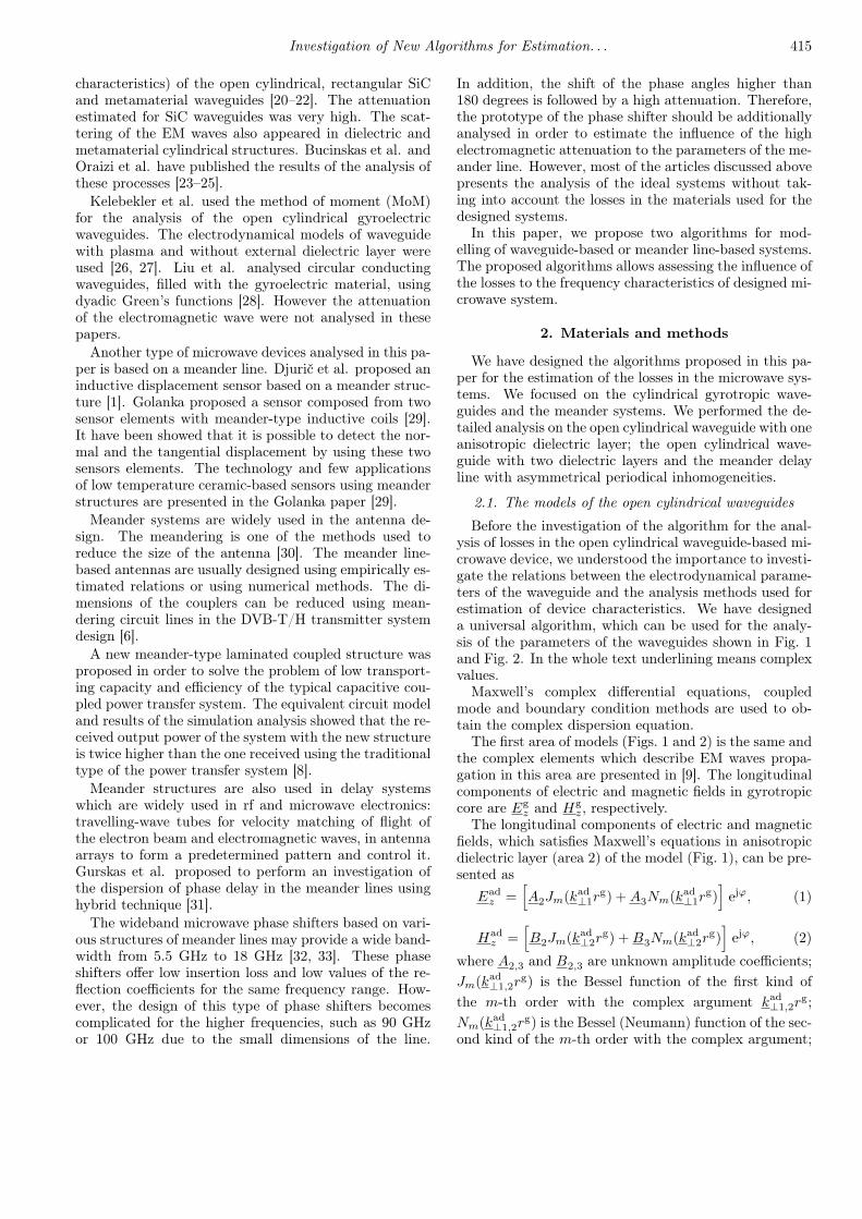
Fig. 1. The electrodynamic model of the open cylin-drical gyrotropic waveguide with anisotropic dielectric
layer, where:↔µ
f
r is the complex permeability tensor ofgyrotropic core; εfr is the complex permittivity of gy-rotropic core;
↔εs
r is the complex permittivity tensor ofgyrotropic core; µs
ris the complex permeability of gy-
rotropic core; µadr is the permeability of anisotropic di-
electric layer;↔εad
r is the complex permittivity tensor ofanisotropic dielectric layer; µa
r is the air permeability;εar is the air permittivity; B0 is the vector of magneticflux density; R is the radius of the waveguide, d is thewidth of the anisotropic dielectric layer and rg is theradius of gyrotropic core.
Fig. 2. The electrodynamic model of open cylindricalgyrotropic waveguide with two dielectric layers, where:µd
r1is the complex permeability of first dielectric layer;
εdr1 is the complex permittivity of first dielectric layer;µd
r2is the complex permeability of second dielectric
layer; εdr2 is the complex permittivity of the second di-electric layer; R1 and R2 are the radii of the dielectriclayers, d1 and d2are the widths of the dielectric layers.
kad⊥1,2 are the transversal wave numbers in anisotropic di-electric layer; m is hybrid mode first (azimuthal) index,describing longitudinal wave constant component by theazimuthal perimeter coordinate ϕ, j =
√−1 is the com-
plex number.The wave’s transversal numbers in anisotropic
(isotropic) dielectric layer can be presented as
kad⊥1 =√k2εadxx − γ2, (3)
kad⊥2 =
√εadzzεadxx
(k2εadxx − γ2
), (4)
where γ = β − jα is the complex propagation constant(here β = Re(γ) = 2π/λw is the phase constant and λw isthe wavelength of the waveguide modes; α = Im(γ) is theattenuation constant); k = ω/c is the wave number in avacuum; εadxx and εadzz are the anisotropic dielectric layertensor diagonal elements.
The third area of models (Figs. 1 and 2) is also thesame. Complex elements, which describe EM wavespropagation in this area, are presented in [9]. The lon-gitudinal components of electric and magnetic fields areEaz and Ha
z , respectively, in air.The azimuthal components of electric Eg,ad,a
ϕ and mag-netic Hg,ad,a
ϕ fields can be obtained from longitudinalcomponents Eg,ad,a
z and Hg,ad,az . The complex disper-
sion equation is obtained by using boundary conditions.The complex dispersion equation of model of the opencylindrical gyrotropic waveguide with anisotropic dielec-tric layer (Fig. 1) is the 8th order determinant expressionD = det(ajk) = 0, where j is a column and k is a rowindex of determinant and ajk are complex elements ofdeterminant.
By using the same method, the complex dispersionequation of model of open cylindrical gyrotropic wave-guide with two dielectric layers can be obtained only inthis case when the complex dispersion equation is the12th order determinant expression.
It was problematic to analyse and select the materialsfor the design of the gyrotropic waveguide based device.The choice of ferrite materials is small but these materialsare distinguished by a low attenuation of the propagat-ing waves in the microwave devices. A large choice ofsemiconductors could be classified by the material type,the type of the material conductivity, the density of freecarriers, the mobility of the carriers, the effective massand the relative permittivity.
It is difficult to perform a physical experiment of thewaveguide based microwave device. First of all the di-ameter of the open cylindrical waveguides is very small.Secondly, these waveguides are long. Thirdly, the coresof the waveguides are hard and fragile and finally thedensity of free carriers should be low. In addition, wewere unable to produce physically the adequate samplesand the investigation limited to the numerical experimentonly.
2.2. Algorithm for the estimation of lossesin the open cylindrical waveguides
The basis of the algorithm 1 proposed for the analysisof the losses in open cylindrical waveguide-based device(OCWs) is presented in Fig. 3. The main difference ofthe algorithm proposed in this paper to the algorithmswe have presented in our previous works [34] lies in the

Investigation of New Algorithms for Estimation. . . 417
Fig. 3. The basic algorithm for the analysis of the opencylindrical waveguides (algorithm 1).
calculation of the complex propagation constant of theEM waves, which allows us to evaluate the attenuationof the EM in OCWs.
Firstly, system parameters of OCWs were initializedin the first block for two calculation cases: (1) initial-ization of the parameters for the OCWs with anisotropicdielectric layer: εsn,pk , N , µ, rg, B0, µad
r , εadr , H, Ms, m,m∗, T , ∆H, µs
r, εfr, R, fmin, fmax, ∆f , βmin, βmax, ∆β;
(2) initialization of the parameters for the OCWs withtwo dielectric layers: εsn,pk , N , µ, rg, B0, µd
r1,2, εdr1,2, H,
Ms, m, m∗, T , ∆H, µsr, εfr, R1,2, fmin, fmax, ∆f , βmin,
βmax, ∆β. Here: εsn,pk is the permittivity of semiconduc-tor core; N is the density of free carries; µ and m∗ arethe mobility and the effective mass of free carries; H isthe external magnetic field strength; ∆H is the width ofthe resonance line; Ms is the magnetization to satura-tion. It is very important to select the initial boundariesof EM wave frequencies fmin and fmax and step of EMfrequency — ∆f . Selection of the initial boundaries ofEM waves phase constants βmin and βmax and step of EMphase — ∆β is also important.
The initialization of indexes of iterations it1 and it2is performed in the second block. The indexes of it-erations depend on lengths of vectors of frequencies fand phase constants β. The vectors f and β consist ofvalues of fmin, fmax, and ∆f , and βmin, βmax and ∆β,respectively.
The calculation of the complex dispersion equation|D|is performed in the third block. This part of the al-gorithm consists of the several parts: calculation of therelative complex permittivity and permeability tensors;calculation of the determinant elements ajk; calculationof the determinant D = det(ajk).
We calculated the phase constants β by searching forthe global minimum in the solution of the dispersionequation |D|(fourth block, see Fig. 3). The extractionof indexes it1 and it2 where is the solution of dispersionequation |D|is performed in the fifth block. We extractedthe phase characteristics of the main and the first highermodes (sixth block, see Fig. 3) by using an algorithm,which was presented in our previous work [34] which isbased on artificial neural networks. These extracted char-acteristics were used for the calculation of the complexpropagation constant γ and for the future analysis tasks.The initialization of the main HE11 and first higher EH11
modes phase constants β vectors and creation α vec-tor of the attenuation constants are performed in 7 and8 blocks of the algorithm. The vector α consists of val-ues of αmin, αmax and ∆α. The initial boundaries ofvector α was αmin = 0, 1/m; αmax = 5000, 1/m and thestep ∆α = 0.025, 1/m. The initialization of new indexesof iterations it1, it2 and it3 is performed in ninth block.The it3 index of iterations depends on length of vector α.
The calculation of the complex dispersion equation|D|is performed in the tenth block of the algorithm,when the complex propagation constant depends on theindexes of iterations. The extraction of extreme of

418 D. Plonis et al.
determinant and indication of locations by indexes it1, it2and it3, and calculation of complex propagation constantby indexes it1, it2 and it3, and the phase and attenuationconstants dependences on the frequency were saved forfuture analysis and the finally graphical representation ofthe phase and attenuation constants dependences on thefrequency were performed in 11–15 blocks of algorithm(Fig. 3).
The electrodynamical parameters of the OCWs werecalculated during sixteenth block of the algorithm.The electrodynamical parameters: cut-off frequencies ofmodes; central frequency of the OCWs; working fre-quency range of the OCWs; bandwidth in percentagesof the OCWs were calculated by using the same method,presented in our previous work [34].
The differential phase shift module was calculated inseventeenth block of the algorithm 1 by selecting fre-quency value in the waveguide working frequency rangeand searching for the intersection of vertical line, drawnat the selected frequency and phase constant character-istics. The differential phase shift module was calculatedby using expression|∆ϑ|f=const = |(β0 − βB0,T )|L360/2π, (5)
where β0 is the phase constant, when B0 = 0, and T is theinitial temperature; βB0,T is the phase constant, whenB0 6= 1 T and T is the higher or lower than initial tem-perature; L is the length of the OCW.
The attenuation constant dependences on the magneticflux density (and temperature) were calculated by usingsimilar method to the differential phase shift module cal-culation. The attenuation constant was calculated byusing expression
αL|f=const= 20 log10(exp(αL)). (6)
Results are saved in the seventeenth block.This developed algorithm could be used for the anal-
ysis of the simple multilayer dielectric waveguides, gasdischarge and dielectric tubes. In addition, it could beadapted for the analysis of the other waveguide models.
There are several important advantages of the first al-gorithm proposed in this paper (see Fig. 3), comparing toestimation of the waveguide characteristics by commer-cial software. First advantage is the ability to estimatethe attenuation constant dependences on the magneticflux density, frequency and temperature for any OCWs.Second, is the ability to estimate the bandwidth, whichis related to the central frequency, differential phase shiftmodule for OCWs designed from various possible mate-rials (only the main features of the material should beprovided). Third, the calculation time, needed to esti-mate this set of parameters is comparatively short andtakes less than 1 min for a OCWs.
2.3. The meander lines with periodical inhomogeneity
Simplified models of the ideal meander delay systemswithout losses were usually used during the analysis ofthe frequency characteristics of the prototype. The at-tenuation is always present in the real meander systems.
Frequently it remains unclear what was the influence ofthe losses caused by attenuation to the frequency char-acteristics of the meander systems. It was important tocreate a universal algorithm for performing an analysisof the influence of losses to the frequency characteristicsof the meander delay systems.
The model of the meander structure with asymmetricalperiodical inhomogeneity or transverse inhomogeneity re-spect to the longitudinal plane was investigated in orderto clarify the influence of losses to the frequency charac-teristics of the meander delay systems in this particularcase. The inhomogeneity in these systems appear due todielectric holders, bending of the conductor of the me-ander electrode, errors of manufacturing and for otherreasons [36]. A fragment of the asymmetrical meanderelectrode with different widths of the narrow conductorsat the peripheral parts is shown in Fig. 4. This asym-metrical meander electrode has been analysed in orderto elucidate whether asymmetrical inhomogeneity affectthe width of pass-band of a meander system.
Fig. 4. The fragment of the asymmetrical meanderelectrode: l2 is the central section of meander electrode,l1, l3 are the peripheral sections of meander electrode.
Fig. 5. The model of the meander delay line: 1 isthe conductor of the multiconductor line; 2, 3 arethe shields; 4 is the resistance Rm in multiconductor linemodel that simulates certain material; n is the numberof conductor; l1, l2, l3 are the lengths of homogeneoussections and x1, x2, x3 are the coordinates of intersec-tions of homogeneous sections in x axis.

Investigation of New Algorithms for Estimation. . . 419
The model of the meander delay line (MDL) con-taining transverse inhomogeneity is presented in Fig. 5.The model consists of three homogeneous sections of themulticonductor line. Their lengths and characteristicimpedances can be different.
Expressions for voltages and currents of the conduc-tors in the multiconductor line were discussed in [36].The multiconductor line models the meander system ifthese modified boundary conditions are satisfied
I1n(0)(Rm/2) + U1n(0) =
U1(n−1)(0) + I1n(0)(Rm/2), (7)
I1n(x1) = I2n(x1), U1n(x1) = U2n(x1), (8)
I2n(x2) = I3n(x2),
U2n(x2) = U3n(x2), I3n(x3) = −I3(n+1)(x3), (9)
I3n(x3)(Rm/2) + U3n(x3) =
U3(n+1)(x3) + I3(n+1)(x3)(Rm/2), (10)
I2(n+1)(x2) = I3(n+1)(x2),
U2(n+1)(x2) = U3(n+1)(x3), (11)
I1(n+1)(x1) = I2(n+1)(x1),
U1(n+1)(x1) = U2(n+1)(x1), (12)where Rm simulates the material of the meander elec-trode. After derivation of the formulae the final expres-sions of frequency f , retardation factor kR and charac-teristic impedances ZC are
f = kc0/2π; (13)
kR = c0/vph = θ/kL; (14)
Re(ZC(x))=U0(x)
I0(x)=− j
A12 +A14
Y (θ)A11+Y (θ+π)A13, (15)
where vph is the phase velocity of the travelling wave,c0 is the light velocity and L is the step of the conduc-tors of the multiconductor line, Y (θ) and Y (θ + π) arethe characteristic admittances and A11, A12, A13, A14,are the coefficients of the A matrix.
2.4. Algorithm for the estimation of lossesin the meander lines
The algorithm 2 is designed to calculate the retarda-tion factor, the input impedance and the transfer char-acteristics of the MDLs. The main difference of the pro-posed algorithm comparing to the algorithms proposedin our previous papers [36] is the use of alternative ma-terial resistance Rm, which allows to evaluate the EMwave losses in the MDLs. The influence of material re-sistance Rm to the frequency characteristics of MDLs re-veals from equations of boundary conditions (7)–(12).
Firstly, parameters of the system of MDLs are initial-ized in the first block: l1, l2,... ln are the lengths ofthe sections of meander electrode; ZC1, ZC2... ZCn arethe characteristic impedances of the meander electrodesections; L is the step between neighbour conductors ofthe meander electrode; Rm is the alternative material re-sistance received in the multiconductor line model thatsimulates certain material and θ is the phase angle be-tween the voltages and currents on the adjacent conduc-tors of the multiconductor line. The number of sectionsof meander electrode may vary depending on the shapeof meander.
Secondly, some additional parameters has to be calcu-lated before working with the dispersion equations in thesecond block of the algorithm. The number of the char-acteristic admittances Y1(θ), Y2(θ),... Yn(θ) depends onthe number of sections of meander electrode. It is alsoimportant to select the initial boundaries θmin and θmax
in the search range of the phase angle θ before startingthe calculation of dispersion equation. It is possible tomiss the solution even in cases when a solution exists ifthe search region is selected incorrectly.
Selection of initial value or recalculation of the phaseangle θ between voltages or currents on the adjacentconductors of the meander electrodes is carried out inthe third block of the algorithm. θ is recalculated bythe chosen step of phase angle ∆θ, which can be ad-justed. The θmin value of phase angle is usually equalto zero. The θmax do not have its limit because voltagesand currents equations are trigonometric functions. Re-sistance Rm in multiconductor line model that simulatescertain material is recalculated depending on the phaseangle θ in the fourth block of the algorithm. Calcula-tion of solutions of dispersion equation begins in the fifthblock of the algorithm. Calculations are carried out in aniterative process. Therefore, the number it of iterations isselected depending on the desired accuracy primarily inthe fifth block. The determinant |D|i,it,idet is calculated3 times near the expected solution at points θmin, θaverage,and θmax in every iteration in the sixth block. Resultsof calculation of three determinants |D|i,it,idet are savedand can be used in the following stages.
Verification is performed in order to check if the so-lution exists in the selected range in the seventh block.Calculations move to the next iteration if there are nosolutions found (third block). Narrowing of the searchrange is carried out if the solution exists. The narrowingis performed by recalculating boundaries θmin and θmax
of the search range of the phase angle θ in the eighthblock of the algorithm. The cycle is interrupted when thedesired accuracy is reached which is defined by the Sal
variable in the ninth block. Values of wave number arecalculated according to the corresponding θ values untilthe desired accuracy is reached and saved. Frequency f ,retardation factor kR, characteristic impedance ZC arecalculated when there is a known relationship between θand wave number in the tenth block of the algorithm.New boundaries θmin and θmax of search range of the
420 D. Plonis et al.
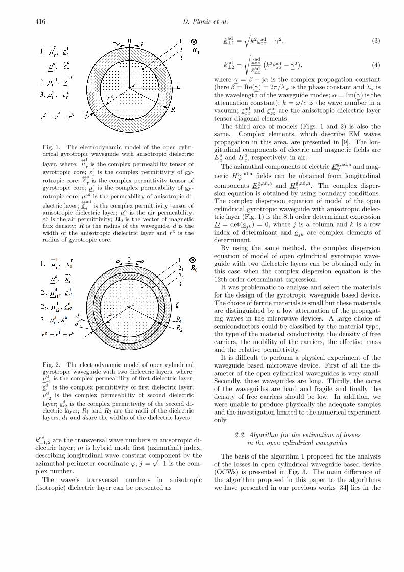
Fig. 6. The basic algorithm for the analysis of the me-ander delay lines (algorithm 2).
phase angle θ are recalculated after return to the fourthblock on condition that it is not the last iteration. Re-sults are saved in the twelfth block if it is the last iter-ation of θi. The calculation of frequency f , retardationfactor kR and characteristic impedance ZC is performedaccording to Eqs. (13)–(15).
The main difference of the proposed algorithm by com-paring it to the algorithms, which are proposed in ourprevious papers [36], occurs and are implemented inblocks 4–10. Material resistance Rm appears in equa-tions of boundary conditions therefore it impacts the cal-culation of solutions of dispersion equations in the sixthblock of the algorithm. The calculation of frequency, re-tardation factor and characteristic impedance dependson solutions of dispersion equations in the tenth block.The introduced alternative material resistance Rm allowsto evaluate the EM wave losses in the MDLs. The de-veloped algorithm could be used for the analysis of anytype of meander structures containing the periodical in-homogeneities and influenced by the attenuation.
The main advantage of the second algorithm, which isproposed in this paper (see Fig. 6), by comparing it toestimation of the same parameters by commercial soft-ware, is the ability to directly estimate the dependencesof the frequency and the retardation factor for the me-ander line. In addition, the characteristic impedance canbe estimated without the need of redesign of the meanderline structure or changing the mathematical model of thedesigned subsystem.
3. Results
In order to compare the loss estimation results withthe alternative methods, we have applied the proposedalgorithms to the microwave systems that have been in-vestigated previously by other authors or by using thecommercial software tools.
3.1. Results of the open cylindrical waveguide analysisalgorithm verification
The model of open waveguide of ISCh4 ferrite wasselected for the verification of the numerical results.The permittivity of ISCh4 ferrite was equal to εfr = 13.5and the tangent of the loss angle was tan δ = 5 × 10⁻⁴
and the complex relative permeability of the waveguidewas equal to µf
r= 1− j5×10−3. Dielectric material, with
the complex permittivity εdr = 9.6(1− j× 10−4) and therelative thickness d/rf = 0.3 was selected for the externaldielectric layer.
Dependences of the attenuation coefficient on the fre-quency of propagating HE11 mode in the ferrite-dielectricISCh4 waveguide are presented in Fig. 7. These resultswere compared by using three different methods: Muller,the mix of the different methods implemented in the com-mercial software CST Microwave Studio® and the algo-rithm proposed by Nickelson et al. [9]. From receivedcharacteristics it is seen that the highest differences be-tween results were received between our proposed algo-rithm and Ref. [9]. The mean difference between results

Investigation of New Algorithms for Estimation. . . 421
was received in frequency range from 35 GHz to 65 GHzas 9%. The highest difference was 35% and it was re-ceived at 25 GHz.
Fig. 7. Dependences of attenuation coefficient on thefrequency of propagated HE11 mode in models of ferrite-dielectric ISCh4 waveguides.
The algorithm or method, which was used to calculatethe attenuation in ferrite-dielectric ISCh4 waveguides,was not given in Nickelson et al. monograph [9]. The dif-ferences between results, received by application of therest two algorithms were very small in all investigatedfrequency range and was about ≈0.01%. These differ-ences are not seen in dependences (Fig. 7).n-GaAs semiconductor was selected for the verifica-
tion of the numerical semiconductor-dielectric waveguideanalysis results. Results were compared for the ma-terials with density of electrons equal to N = 1019;1020 m−3 and setting different temperature T = 125,150, 175, 200 K. Dependences of semiconductor-dielectricwaveguides where calculated when external dielectriclayer relative thickness is d/rs = 0.3 and EM wave fre-quency is f = 30 GHz. Rb1−x(ND4)D2PO4 dielectricwas selected for external dielectric layer [35]. The dif-ferential phase shift module and attenuation constanton different temperatures of semiconductor-dielectric n-GaAs waveguides were compared by using the proposedalgorithm 1 and the CST Microwave Studio®.
Dependences of the differential phase shift module ontemperature of main HE11 mode of the semiconductor-dielectric n-GaAs waveguides are presented in Fig. 8.It is seen from the characteristics (Fig. 8) that thesewaveguides could work as phase shifters in the rangefrom 125 K to 150 K and in the range from 175 Kto 200 K. The highest differential phase shift modulewas received in these two ranges of the temperature.The highest differential phase shift module was receivedfor the material with density of electrons N = 1020 m−3(Fig. 8b).
It is seen from the results that the highest differences ofcalculated results were in temperature range from 150 Kto 175 K and the difference seeks ≈15.2%. The differ-ence between results decreased at the highest tempera-ture. The difference was ≈3.07%, when temperature isT = 200 K and N = 1019 m−3 (Fig. 8a). The difference
Fig. 8. Dependences of differential phase shift moduleon the temperature of propagated HE11 mode in modelsof semiconductor-dielectric n-GaAs waveguides: 1 —algorithm 1; 2 — CST Microwave Studio, where (a) —N = 1019 m−3 (b) —N = 1020 m−3.
between results increased until ≈0.6% in temperaturerange from 150 K to 175 K and until ≈0.43%, for thematerial with N = 1020 m−3 — a ten times higher den-sity of electrons (Fig. 8b).
Fig. 9. Dependences of attenuation constant on thetemperature of propagated HE11 mode in models ofsemiconductor-dielectric n-GaAs waveguides: 1 — algo-rithm 1; 2 — CST Microwave Studio, where N = 1019;1020 m−3.
Dependences between the attenuation constantand the temperature of the main HE11 mode ofsemiconductor-dielectric n-GaAs waveguides are pre-sented in Fig. 9. It is seen that EM wave attenuationincreased when the density of electrons N was higher.However, it is seen that the better way is to use thesemiconductor-dielectric waveguides with lower densityof electrons.
The lower difference between results was received atthe temperature T = 175 K. The difference was ≈5.3%in all investigation cases. However, the difference be-tween results was the same in two temperature rangesfrom 137 K to 170 K and from 180 K to 192 K. It meansthat the algorithms for the calculation of attenuationwork almost similar. At the highest temperatures, thedifferences between results decreased to ≈1%.
422 D. Plonis et al.
3.2. Results of the meander structures analysisalgorithm verification
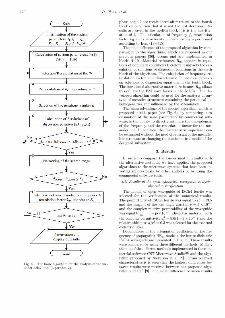
The model of the MDL with transverse inhomo-geneities was investigated in order to elucidate influenceof the periodical symmetrical and asymmetrical inhomo-geneities on the frequency characteristics of the meanderdelay system. Results of the retardation factor and inputimpedance versus frequency of simulation experiment ofMDL regardless of losses are presented in Fig. 10.
Fig. 10. Retardation factor (a) and inputimpedance (b) versus frequency of the inhomogeneousmeander delay line at x3 = l1 + l2 + l3 = 20, L = 2 mmand: 1 — l1 = 5 mm, l2 = 10 mm, l3 = 5 mm,Z1(0)/Z1(π) = 60/40 Ω, Z2(0)/Z2(π) = 60/40 Ω,Z3(0)/Z3(π) = 60/40 Ω; 2 — l1 = 5 mm,l2 = 10 mm, l3 = 5 mm, Z1(0)/Z1(π) = 70/50 Ω,Z2(0)/Z2(π) = 50/30 Ω, Z3(0)/Z3(π) = 70/50 Ω;3 — l1 = 5 mm, l2 = 10 mm, l3 = 5 mm,Z1(0)/Z1(π) = 70/50 Ω, Z2(0)/Z2(π) = 50/30 Ω,Z3(0)/Z3(π) = 60/40 Ω; 4 — l1 = 10 mm,l2 = 5 mm, l3 = 5 mm, Z1(0)/Z1(π) = 50/50 Ω,Z2(0)/Z2(π) = 50/30 Ω, Z3(0)/Z3(π) = 70/50 Ω.
At constant characteristic impedances of the meanderconductors the frequency characteristics of the MDL werecontinuous (curves 1 in Fig. 10a,b). Relatively great dis-persion of the retardation and small variation of the inputimpedance were received in homogeneous MDL charac-teristics. These results corresponded to those, which werereceived in previous research work [36].
In traveling-wave deflection systems, the meander elec-trodes containing wide central parts of the meander con-ductors and narrowed the peripheral parts were used forinvestigation (in order to receive the high sensitivity ofthe cathode-ray tube and the high impedance of its sig-nal path). Characteristics of the model of such MDLare presented by curves 2 in Fig. 10a,b. According to
the received input impedance frequency characteristics(Fig. 10b), the input impedance of the system changedrapidly with increased frequency and the stop-band ap-peared at the phase angle θ values approached to π.The received cut-off frequency can be expressed by thefollowing equation:
fc,π = 1/(2td), (16)where td ∼= x3kR/Lc0 is the delay time corresponding tothe step of meander conductors.
The remaining two curves presented in Fig. 10a,b illus-trates the influence of the asymmetrical inhomogeneitieson the properties of MDL. The received curves 3 were ob-tained at different peripheral parts of the MDL, curves 4— at the shifted central part of the meander electrode(different lengths of peripheral parts). Comparing thecharacteristics 3 and 4 with the characteristic of theMDL with transverse symmetry (curves 1 and 2) it canbe found that the asymmetry of the system causes radi-cal changes of its frequency properties. At the asymme-try range the input impedance rapidly changed when thephase angle θ approached π/2. As a result, the disconti-nuity of the frequency characteristics and the stop bandappeared at cut-off frequency, which can be expressed bythe following equation:
fc,π/2 = 1/(4td). (17)Effects caused by the asymmetry can be explained tak-ing into account that at the transverse asymmetry theperiod of the inhomogeneities along the meander conduc-tor becomes twice greater with respect to the period ofinhomogeneities at the absence of transverse asymmetry.
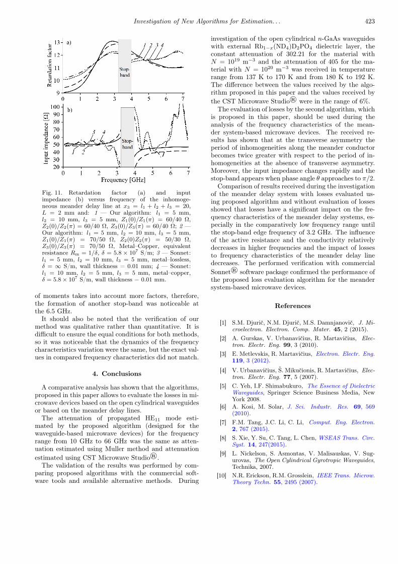
Results (1, 2 curves — our algorithm, 3, 4 curves —Sonnet®) of the received retardation factor and the in-put impedance versus frequency of the MDL, taking intoaccount losses in conductors when using equivalent re-sistance Rm, are presented in Fig. 11. The verifica-tion of our algorithm was performed using the Sonnet®software package. Copper with conductivity equal to5.8× 107 S/m was selected for analysis in Sonnet® pro-gramming package. Copper material was simulated bychoosing the equivalent resistance Rm in our algorithm.The equivalent resistance Rm was selected to match theresistance of the copper, selected in Sonnet® package.
It is seen in Fig. 11 that the influence of losses was ev-ident and the biggest impact of losses was received in thelower frequencies until the stop-band for the analysis re-sults obtained by our method (see 1, 2 curves in Fig. 11).The retardation factor was higher in low frequencies andwas smaller near the stop-band in system with losses.The influence of the active resistance and conductivityrelatively decreased with the increased frequency. In ad-dition, the impact of losses to the frequency character-istics of the meander line decreased. The results ob-tained using our method were validated using commercialSonnet® software package (see 3, 4 curves in Fig. 11).Sonnet® uses the method of moments applied directly toMaxwell’s equations to solve planar problems. Method
Investigation of New Algorithms for Estimation. . . 423
Fig. 11. Retardation factor (a) and inputimpedance (b) versus frequency of the inhomoge-neous meander delay line at x3 = l1 + l2 + l3 = 20,L = 2 mm and: 1 — Our algorithm: l1 = 5 mm,l2 = 10 mm, l3 = 5 mm, Z1(0)/Z1(π) = 60/40 Ω,Z2(0)/Z2(π) = 60/40 Ω, Z3(0)/Z3(π) = 60/40 Ω; 2 —Our algorithm: l1 = 5 mm, l2 = 10 mm, l3 = 5 mm,Z1(0)/Z1(π) = 70/50 Ω, Z2(0)Z2(π) = 50/30 Ω,Z3(0)/Z3(π) = 70/50 Ω, Metal–Copper, equivalentresistance Rm = 1/δ, δ = 5.8 × 10⁷ S/m; 3 — Sonnet:l1 = 5 mm, l2 = 10 mm, l3 = 5 mm, metal–lossless,δ = ∞ S/m, wall thickness = 0.01 mm; 4 — Sonnet:l1 = 10 mm, l2 = 5 mm, l3 = 5 mm, metal–copper,δ = 5.8× 10⁷ S/m, wall thickness = 0.01 mm.
of moments takes into account more factors, therefore,the formation of another stop-band was noticeable atthe 6.5 GHz.
It should also be noted that the verification of ourmethod was qualitative rather than quantitative. It isdifficult to ensure the equal conditions for both methods,so it was noticeable that the dynamics of the frequencycharacteristics variation were the same, but the exact val-ues in compared frequency characteristics did not match.
4. Conclusions
A comparative analysis has shown that the algorithms,proposed in this paper allows to evaluate the losses in mi-crowave devices based on the open cylindrical waveguidesor based on the meander delay lines.
The attenuation of propagated HE11 mode esti-mated by the proposed algorithm (designed for thewaveguide-based microwave devices) for the frequencyrange from 10 GHz to 66 GHz was the same as atten-uation estimated using Muller method and attenuationestimated using CST Microwave Studio®.
The validation of the results was performed by com-paring proposed algorithms with the commercial soft-ware tools and available alternative methods. During
investigation of the open cylindrical n-GaAs waveguideswith external Rb1−x(ND4)D2PO4 dielectric layer, theconstant attenuation of 302.21 for the material withN = 1019 m−3 and the attenuation of 405 for the ma-terial with N = 1020 m−3 was received in temperaturerange from 137 K to 170 K and from 180 K to 192 K.The difference between the values received by the algo-rithm proposed in this paper and the values received bythe CST Microwave Studio® were in the range of 6%.
The evaluation of losses by the second algorithm, whichis proposed in this paper, should be used during theanalysis of the frequency characteristics of the mean-der system-based microwave devices. The received re-sults has shown that at the transverse asymmetry theperiod of inhomogeneities along the meander conductorbecomes twice greater with respect to the period of in-homogeneities at the absence of transverse asymmetry.Moreover, the input impedance changes rapidly and thestop-band appears when phase angle θ approaches to π/2.
Comparison of results received during the investigationof the meander delay system with losses evaluated us-ing proposed algorithm and without evaluation of lossesshowed that losses have a significant impact on the fre-quency characteristics of the meander delay systems, es-pecially in the comparatively low frequency range untilthe stop-band edge frequency of 3.2 GHz. The influenceof the active resistance and the conductivity relativelydecreases in higher frequencies and the impact of lossesto frequency characteristics of the meander delay linedecreases. The performed verification with commercialSonnet® software package confirmed the performance ofthe proposed loss evaluation algorithm for the meandersystem-based microwave devices.
References
[1] S.M. Djurič, N.M. Djurič, M.S. Damnjanovič, J. Mi-croelectron. Electron. Comp. Mater. 45, 2 (2015).
[2] A. Gurskas, V. Urbanavičius, R. Martavičius, Elec-tron. Electr. Eng. 99, 3 (2010).
[3] E. Metlevskis, R. Martavičius, Electron. Electr. Eng.119, 3 (2012).
[4] V. Urbanavičius, Š. Mikučionis, R. Martavičius, Elec-tron. Electr. Eng. 77, 5 (2007).
[5] C. Yeh, I.F. Shimabukuro, The Essence of DielectricWaveguides, Springer Science Business Media, NewYork 2008.
[6] A. Kosi, M. Solar, J. Sci. Industr. Res. 69, 569(2010).
[7] F.M. Tang, J.C. Li, C. Li, Comput. Eng. Electron.2, 767 (2015).
[8] S. Xie, Y. Su, C. Tang, L. Chen, WSEAS Trans. Circ.Syst. 14, 247(2015).
[9] L. Nickelson, S. Asmontas, V. Malisauskas, V. Sug-urovas, The Open Cylindrical Gyrotropic Waveguides,Technika, 2007.
[10] N.R. Erickson, R.M. Grosslein, IEEE Trans. Microw.Theory Techn. 55, 2495 (2007).

424 D. Plonis et al.
[11] S.S. Iqbal, A.A. Gibson, in: Proc. 11th Int. Conf.on Antennas and Propagation, IET, Manchester 2001,p. 323.
[12] S.S. Iqbal, Microw. Opt. Technol. Lett. 39, 4 (2003).[13] A. Bubnelis, L. Nickelson, R. Martavicius, in: Proc.
MIKON 2012, 19th Int. Conf. on Microwaves, Radarand Wireless Communications, Warsaw (Poland),Ed. R. Kubacki, IEEE, Warsaw 2012, p. 487.
[14] Y.J. Huang, W.T. Lu, S. Sridhar, Phys. Rev. A 77,11 (2008).
[15] Q. Zhang, T. Jiang, Y. Feng, in: Proc. MicrowaveConf., Ed. F. Lin, IEEE, Singapore 2009, p. 1242.
[16] H. Lin, A.I. Zaki, IEEE Trans. Magn. 25, 252950(1989).
[17] I.R. Belous, in: Proc. the Fourth Int. KharkovSymp., IEEE, Kharkov 2001, p. 600.
[18] B.P. Catrysse, S. Fan, in: 21st Annual Meeting ofthe IEEE Lasers and Electro-Optics Society, 2008.
[19] L. Nickelson, S. Asmontas, V. Malisauskas, R. Mar-tavicius, J. Plasma Phys. 75, 1 (2008).
[20] L. Nickelson, T. Gric, S. Asmontas, R. Martavicius,Electron. Electr. Eng., 93 87(2009).
[21] L. Nickelson, S. Asmontas, T. Gric, R. Martavi-cius, in: Progress in Electromagnetics ResearchSymp., Moscow (Russia), Electromagnetics Academy,Moscow 2009, p. 573.
[22] T. Gric, L. Nickelson, S. Asmontas, Progr. Electro-magn. Res. 109, 361 (2010).
[23] J. Bucinskas, L. Nickelson, V. Shugurovas, Progr.Electromagn. Res. 105, 103 (2010).
[24] H. Oraizi, A. Abdolali, Progr. Electromagn. Res.78, 129 (2008).
[25] J. Bucinskas, L. Nickelson, V. Shugurovas, Progr.Electromagn. Res. 109, 175 (2010).
[26] E. Kelebekler, N. Yener, in: Progress in Electromag-netics Research Symp. Proc., Marrakesh (Morocco),Marrakesh 2011, p. 1084.
[27] E. Kelebekler, Progr. Electromagn. Res. B 54, 357(2013).
[28] S. Liu, L.W. Li, M.S. Leong, T.S. Yeo, Progr. Elec-tromagn. Res. 29, 231 (2000).
[29] L. J. Golanka, Bull. Pol. Acad. Sci. Techn. Sci.54, 2 (2006).
[30] P. Vikram, H.V. Kumaraswamy, R.K. Manjunath,Int. J. Adv. Res. Comput. Commun. Eng., 4 (2015).
[31] A. Gurskas, A. Krukonis, V. Urbanavicius, Electron.Electr. Eng. 21, 2 (2015).
[32] A.A. Eldek, Progr. Electromagn. Res. B 2,177(2008).
[33] Q.W. Che, N.K.E. Yung, K. Wu, D.X. Nie, Progr.Electromagn. Res. 45, 263 (2004).
[34] D. Plonis, V. Malisauskas, A. Serackis, Acta Phys.Pol. A 119, 542 (2011).
[35] S. Štaras, R. Martavičius, J. Skudutis, V. Urbanav-ičius, V. Daškevičius, Wide-Band Slow-Wave Sys-tems: Simulation and Application, CRC Press, BocaRaton 2012.
[36] A. Katkevičius, S. Štaras, Electron. Electr. Eng. 2,108 (2011).
[37] J. Banys, A. Kajokas, S. Lapinskas, A. Brilingas,J. Grigas, J. Petzelt, S. Kamba, J. Phys. Condens.Matter 14, 14 (2002).