Embed Size (px)
Citation preview

© 2019 JETIR April 2019, Volume 6, Issue 4 www.jetir.org (ISSN-2349-5162)
JETIRBB060185 Journal of Emerging Technologies and Innovative Research (JETIR) www.jetir.org 969
Investigation of Mechanical Properties of
Copper Plated ABS Part with Different
Layer Thickness Kiran Gojre
a Department of production Engineering, COE, ,Pune-411028,India
Abstract
Fused deposition modelling (FDM) is most commonly used processes in additive manufacturing. FDM uses raw
material in the form of wire filament and works on the principle of extrusion. Acrylonitrile butadiene styrene (ABS) is
commonly used engineering plastic in FDM process for printing different parts for functional purpose or prototyping. As ABS
is less expensive material among other plastic used in FDM process. The availability and cost of ABS highlights its more use
in additive manufacturing. Mechanical properties of ABS can be enhanced by copper plating. Copper plating on ABS can
provide good tensile strength and impact resistance to the ABS parts. . To optimize the printing parameters using taguchi’s
method, Minitab software is used to generate optimum number of combinations for printing of ABS parts. This work describes
the detail study on investigating the physical and mechanical properties of ABS part without plated and copper plated ABS
parts with different layer thickness 50µm, 200µm, 400µm and 600µm. Tensile strength, impact strength and hardness values
for these different parts are found by various experimental tests. Focusing on the end results it was observed that after
coating 600 micron layer of copper over 3D printed specimens, tensile strength is increased by 321.67% , whereas Mirco
Hardeness by 139% and Impact strength is increased by 190% than existing properties of as printed specimens. It can be
concluded that copper coating provides better option for improvement in mechanical properties of 3D printed parts without
considerable variation in weight of parts or going for expensive metal printing process. Keywords: FDM, ABS, Tensile strength,Impact strength, Hardness, Copper plating Introduction
I. Introduction
Our world is growing faster with sustainable development in
the fields of science and technology. Use of renewable energy
sources and reduction in the
waste generation has given more importance in this century.
Similarly the manufacturing industries are using advance
technologies for betterment of effective conversion of
conceptual designs of product to complete finished product.
Additive manufacturing technology has provided a great
advantage for attaining good accuracy and complexity of
production. As Additive manufacturing finds it’s applications
in various fields like space, aerospace, defence, architectural,
medical, artificial jewelleries, automotive and other
prototyping activities. Additive manufacturing give additional
advantage of no waste material generation. Fused deposition
modelling (FDM) is one of the widely used processes in
additive manufacturing. FDM uses raw material in the form of
wire filament and works on the principle of extrusion. FDM
allows using various engineering plastics like Acrylonitrile
butadiene styrene (ABS), Acrylonitrile styrene acrylate
(ASA), Polycarbonate (PC), Polyphenylsulfone (PPSF),
Polyetherimide (ULTEM) and Nylon for building of
prototypes. ABS is most commonly used thermoplastic
polymer for FDM process as it has significant mechanical
properties like impact resistance and toughness as well as less
expensive compared to the other high performing plastics.
Normally ABS parts perform better within a temperature
range from −20 to 80 °C (−4 to 176 °F). Besides these ABS is
chemical stable against the aqueous acids and alkalis. Many
of FDM machines permit the adjustment of general process
parameters, consist of temperature range of nozzle and build
platform, the building speed, the layer thickness and rpm of
the cooling fan. These parameters are generally set by the
machine operator instead of product designer.
Jason T Cantrell et. al. [1] presented work on the
characterization of 3D printed (using FDM Process)
acrylonitrile butadiene styrene (ABS) and Polycarbonate (PC)
parts by adopting digital image correlation (DIC) method.
Printed parts are built with different orientations and raster
angles ([+45/-45], [+30/-60], [+15/-75], [0/90] in order to
finding out the directional properties of materials. These parts
are examined for the tensile and shear characteristics based on
the parameters like Young’s modulus, Poisson’s ratio, tensile
strength at yield, offset yield strength, elongation at break,
tensile stress at break, and strain energy density. It was
observed that build orientation and raster angles does not
affect the young’s modulus or poisons ratio in ABS
specimens, Whereas in case of shear modulus & shear offset
yield strength shown variation up to 33%. For PC parts it has
shown anisotropic behaviour due to change in raster angles as
it shown 20% variations in values of moduli and strengths.

© 2019 JETIR April 2019, Volume 6, Issue 4 www.jetir.org (ISSN-2349-5162)
JETIRBB060185 Journal of Emerging Technologies and Innovative Research (JETIR) www.jetir.org 970
K. Raja et. al. [2] made efforts for enhancing the corrosion
resistance and hardness of the copper coated FDM printed 3D
ABS parts. It consisting of controlling the coating layer
thickness up to 50-54 micrometres which gives hardness
value of 225 VHN. Similarly the effect corrosion on the parts
is studied using the scanning electron microscope.
Azhar Euqbal at. al. [3] made an effort of copper coating of
FDM printed ABS parts by the use of different acidic baths
namely HF (hydrofluoric acid), H2SO4 (sulphuric acid), 5
wt% CuSO4 (copper sulphate) with 15 wt% of individual
acids, H3PO4 (phosphoric acid) and CH3COOH (acetic
acid).During the pre-stage of the coating process the parts
were taken through use of two different etching agents
chromic acid and solution mixture of sulphuric acid.
Performances of different coating through these baths are
examined by the electrical characteristics and use of scanning
electron microscope (SEM) as well as energy dispersive X-
ray spectrometry (EDS). It was observed that chromic acid
etched samples revealed the better electrical performance
when compared to other etched part in sulphuric acid.
S. Kannan et. al. [4] study show a significant work on the
nickel and chrome plated 3D printed ABS parts (using FDM
process) with different layer thickness of 60 μm, 70 μm and
80 μm respectively. These specimens were examined for the
performance in impact resistance and hardness under these
different electroplated layers of nickel and chrome. In order to
evaluate the impact resistance of specimens drop test was
conducted wherein the different drop weights of 0.89kg,
1.39Kg and 2.33Kg were used for drop test. It was observed
that there was considerable increase in impact resistance with
respective increase in coating layer thickness. Similarly these
specimens were gone through Rockwell hardness test which
shown improved values of hardness with respect to increase in
the coating layer thickness.
S. Kannan et. al. [5] used FDM process for printing ABS
specimens and these specimens were electroplated with
copper having varying thickness of 60 μm, 70 μm and 80 μm.
These samples were subjected to acid test and surface
roughness measurements. Tensile strength of the specimen
increased with increase in plating thickness as result there was
comparable increase in the ductility of specimens with
increasing plating thickness.
Jiushuai Xu et. al. [6] controlled the copper coating process
and improved the adhesive strength of coating over the 3D
printed ABS parts by using some modified substrates of ABS.
These copper films for individual deposition rate and angles
were examined by use of scanning electron microscopy
(SEM) and X-ray diffraction (XRD).
H N Zhang et. al. [7] conducted similar experiment on the
self-assembled film modified ABS resin treated with copper
plating. Investigation is done to analyse the surface
appearance, deposition rate and thickness of copper film over
the ABS. It was observed that there was good adhesion
between ABS resin and copper.
Anoop Kumar Sood et. al. [8] shows the influence of layer
thickness, orientation, raster angle, raster width and air gap on
tensile, flexural and impact strength of test specimen. This
work has adopted the ANOVA method for analysis of
variance in the parameters with respective the response
surface plots. Accordingly the optimal parameter setting for
respective response is obtained. It was observed that parts
were having weak strength due to distortion between the
layers.
Anoop Kumar Sood et. al. [9] studied the influence of
important process parameters such as raster angle, layer
thickness, part orientation and air gap on dimensional
accuracy of fused deposition modelling (FDM) printed ABS
P400 part. After printing of the part it is investigated that
shrinkage occurs in part has dominance on length when
compare with width of the part. Henceforth to find out the
optimum parameter for eliminating the shrinkage defect, the
parameters are optimized using the grey taguchi’s method.
Based on the nonlinear responses it is observed that artificial
neural network is suitable for predicting such parameters.
Wang Gui-xiang [10] attempted the direct copper coating on
ABS plastic. Study of the coating is conducted by atomic
force microscopy (AFM), Ultraviolet- visible absorption
spectrometry and X-ray fluorescence spectroscopy (XRF)
methods. ABS substrate were etched by CrO3/H2SO4
solutions containing Pd2+ions, process is catalysed by Pd/Sn
colloids solutions and accelerated in alkaline solutions
containing copper ions. It was observed that etching reduces
surface roughness and enhanced the colloid dispersivity. Also
the size of copper particle affects the uniformity of the copper
plating.
1. ABS Sample Printing
Some of the significant parameters that would affect the print
quality and strength were taken into consideration based on
the research. For generating the number of experiments
according to the selected parameter and three variable
taguchi’s method play a vital role.
Table 01 Factors and variables under consideration
As this method is more suitable to optimize parameters
namely printing strength, print pattern, print fill spacing and
number of top as well as bottom layers in 3D printing of ABS
parts as shown in above table 01.
Fig. 01 Experiments generated by Taguchi’s Method

© 2019 JETIR April 2019, Volume 6, Issue 4 www.jetir.org (ISSN-2349-5162)
JETIRBB060185 Journal of Emerging Technologies and Innovative Research (JETIR) www.jetir.org 971
To generate number of experiments by taguchi’s method as
shown in fig 01, Minitab software is used. After give the
number of input parameters and number of variable it shows
these experiments. In order to print with these different
parameters on FDM it is required to set this parameter on the
system software. Geometry of the specimens is different
according to type of tests on the specimens to be conducted.
Error percentage was reduced by adjusting the scale factor
according so printing accuracy is good enough to compare the
printed parts with the CAD geometry.
A. Measurement of Porosity
Porosity in FDM is defined as the inherent result of molten
material being extruded and fused layer by layer. Fig.02
shows the internal pores between the layers seen on the
microscope. Further to deal with mechanical or other
physical properties it was necessary to determine the porosity
of the printed samples of ABS. Porosity values estimated for
the nine experiments and 3 specimen’s i.e for all 27 ABS
samples.
Fig.02 Internal pores between the layers actual image
Average values are normally varied from range 20%to 51%
which depending upon the printing parameters. Experiment
no 6 showed highest porosity percentage of 50.56% and
fastest printing time while Experiment no 8 had the lowest
porosity of 25.54% with maximum build time. The
experiment No 6 showed maximum porosity as the factors
influencing the print were the maximum print fill spacing of
3mm with the print pattern of honeycomb structure and with
minimum no of top and bottom layers. While on the other
hand, Experiment No 8 had minimum porosity as its print
strength was set to solid, with minimum print fill spacing of
1mm and with a diamond print pattern.
B. Measurement of Roughness
Surface finish which also recognized as surface topography is
generally consists of small local deviations of a surface from
the perfectly flat ideal reference plane. Each manufacturing
process produces a surface texture. If necessary, an additional
post processing will be added to enhance the finish of the
printed parts. Surface roughness termed as roughness, is a
measure of finely spaced surface irregularities. FDM
technology in RP process results in coarse surface finish.
Measurement of surface finish is done in two different ways:
contact and non-contact method.
Fig. 02 Roughness measurement
Contact type surface measurement method uses a touch probe
type surface roughness measuring machine as show in the
above fig 02. Surface roughness (Ra) is described as the
roughness average of a surfaces measured as microscopic
peaks and valleys. Root Mean Square (RMS) of surfaces is
measure of microscopic peaks and valleys.
Fig. 03 Roughness values for experiments
It was observed that surface finish varied from 6.2 Ra to 8.3
Ra of the printed samples as shown in figure 03. Experiment 8
was influenced with a solid print pattern and minimum fill
spacing of 1mm, hence it showed best surface finish among
the other parameters. While experiment 1 has maximum
roughness due to the hollow print strength and cross print
pattern.
C. Measurement of Tensile strength
Mechanical Properties that are directly measured via a tensile
test are ultimate tensile strength, maximum elongation and
reduction in area. From these measurements the following
properties can also be determined: Young's modulus,
Poisson's ratio, yield strength, and strain-hardening
characteristics. Uniaxial tensile testing is the most commonly
used for obtaining the mechanical characteristics of isotropic
materials. Plastic tensile dog-bone shaped specimens are
made to ASTM test sample dimensions.
Fig. 04 Standard Dimension of Tensile test specimen
The tensile test was conducted in accordance with ASTM
D638 standard of tensile testing for polymers. As per this
standard, this test method can be used to test samples upto
14mm thickness. This data is especially useful for the
qualitative characterization. The dimensions required for the
part to be tested were derived from this standard as shown in
figure 04 above.
Fig. 05 UTM setup for Tensile Test
This test was conducted with the help of UTM of 2-Ton
capacity (Make: Universal) specifically designed for
© 2019 JETIR April 2019, Volume 6, Issue 4 www.jetir.org (ISSN-2349-5162)
JETIRBB060185 Journal of Emerging Technologies and Innovative Research (JETIR) www.jetir.org 972
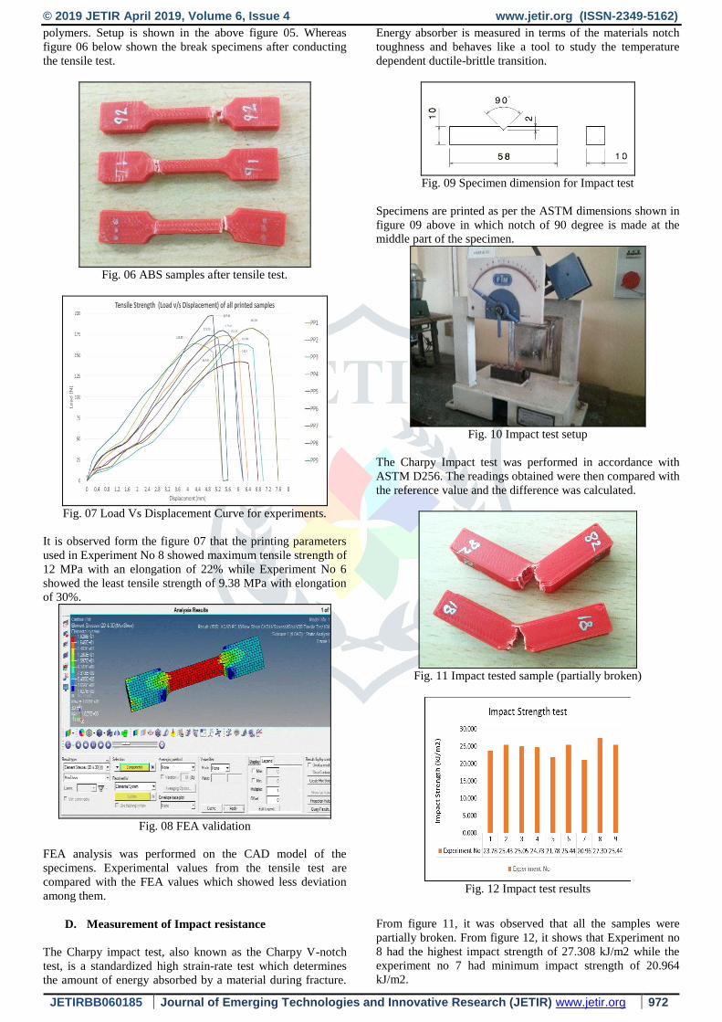
polymers. Setup is shown in the above figure 05. Whereas
figure 06 below shown the break specimens after conducting
the tensile test.
Fig. 06 ABS samples after tensile test.
Fig. 07 Load Vs Displacement Curve for experiments.
It is observed form the figure 07 that the printing parameters
used in Experiment No 8 showed maximum tensile strength of
12 MPa with an elongation of 22% while Experiment No 6
showed the least tensile strength of 9.38 MPa with elongation
of 30%.
Fig. 08 FEA validation
FEA analysis was performed on the CAD model of the
specimens. Experimental values from the tensile test are
compared with the FEA values which showed less deviation
among them.
D. Measurement of Impact resistance
The Charpy impact test, also known as the Charpy V-notch
test, is a standardized high strain-rate test which determines
the amount of energy absorbed by a material during fracture.
Energy absorber is measured in terms of the materials notch
toughness and behaves like a tool to study the temperature
dependent ductile-brittle transition.
Fig. 09 Specimen dimension for Impact test
Specimens are printed as per the ASTM dimensions shown in
figure 09 above in which notch of 90 degree is made at the
middle part of the specimen.
Fig. 10 Impact test setup
The Charpy Impact test was performed in accordance with
ASTM D256. The readings obtained were then compared with
the reference value and the difference was calculated.
Fig. 11 Impact tested sample (partially broken)
Fig. 12 Impact test results
From figure 11, it was observed that all the samples were
partially broken. From figure 12, it shows that Experiment no
8 had the highest impact strength of 27.308 kJ/m2 while the
experiment no 7 had minimum impact strength of 20.964
kJ/m2.

© 2019 JETIR April 2019, Volume 6, Issue 4 www.jetir.org (ISSN-2349-5162)
JETIRBB060185 Journal of Emerging Technologies and Innovative Research (JETIR) www.jetir.org 973
E. Metallization of ABS Parts:
Metallizing is the process of plating the surface of non-
metallic components for purpose of protection, decoration or
functional applications. Coating of ABS parts give improved
mechanical properties. The ABS part fabricated through FDM
is better than molded ABS parts, as the parts produced
through FDM have a higher surface roughness, which is
advantageous for depositing the catalysts on the part during
the metallization process.
Fig. 13 Flow chart for copper plating process
Copper plating process was carried out following various step
mentioned in above figure 13 which involves etching of
specimens, washing and cleaning, palladium activation
process, electro-less nickel plating , acid dip, later on copper
plating then again acid dip and finally with anti-tarnishing.
Fig. 14 Copper plating of various layer thickness
As above figure 14 shows the different layer thickness of
copper plating obtained using same current densities but
requires different time span to obtain the desired thickness of
layers on ABS parts. At first, all the FDM printed parts were
copper electroplated with a film thickness of 50 microns.
They were checked for the mechanical and physical
properties. It was found out that the experiment no 8 was
showing the best results. Hence it’s decided further to print
number of parts with the parameters used for experiment no 8
and coated these specific samples with 200, 400 and 600
microns to study the effect of plating thickness on the printing
parameters.
Fig.15 Layer thickness measurement actual images
The plated samples were examined for the plating thickness
with the help of a digital microscope as shown in figure 15.
The thickness before and after plating was noted and the
difference was calculated to be the thickness of the plating on
both the sides of the specimen. The results show that, porosity
percentage did not have much impact on the film thickness
deposition. During the plating process, if the sealing process
of the part was carried out properly, there was no difference
observed in plating thickness to be achieved. Hence sealing of
the part becomes a critical operation while going for the
electroplating copper process.
F. Measurement of Micro Hardness:
Micro hardness test are generally used to determine the
hardness value of polymer and rubber used for different
engineering applications. These test uses indenter to perform
the operation of penetration on the test specimen surface and
permissible deformations are measured on the setup. Using
these values the hardness values are estimated of the test
specimens. Micro hardness testing is a well-known non-
destructive technique to obtain information on structural
features and change in mechanical properties of pure
polymers and polymer blends. This test requires an
application of force with lesser amount compared with
standard measurements. Indentations obtained on the
specimen surface are very tiny hence microscopic
measurements are used to determine deformations.
Fig. 16 Micro Hardness Measurement Test setup

© 2019 JETIR April 2019, Volume 6, Issue 4 www.jetir.org (ISSN-2349-5162)
JETIRBB060185 Journal of Emerging Technologies and Innovative Research (JETIR) www.jetir.org 974
Measurement of hardness is performed using the micro
hardness test setup as shown in above figure 16. This uses
small indenter for penetration and a microscopic digital
instrument to measure the surface distortion.
G. Comparison of Parameters :
Comparison of tensile strengths for specimens:
Fig. 17 Comparison of the tensile strength of as printed
samples with different copper coated samples.
Fig 18 Sample before tensile test
Fig 19 Samples broke after tensile test
Comparison of impact strengths for specimens:
Fig 20 Comparison of impact strength for non-coated and
coated ABS parts
Comparison of hardness
Fig 21 Comparison of Hardness for non-coated and coated
ABS parts
Conclusion:
Focusing on the end results it was observed that after coating
600 micron layer of copper over 3D printed specimens, tensile
strength is increased by 321.67% , whereas Mirco Hardeness
by 139% and Impact strength is increased by 190% than
existing properties of as printed specimens. It can be
concluded that copper coating provides better option for
improvement in mechanical properties of 3D printed parts
without considerable variation in weight of parts or going for
expensive metal printing process.
Acknowledgments
We thank Mr. Ketan Jagadishrao Mahamuni (M.E
Mechanical Design) for their valuable contribution in
completing this article.
References
[1] Jason T Cantrell, Sean Rohde, David Damiani, Rishi Gurnani, Luke
DiSandro, Josh Anton, Andie Young, Alex Jerez, Douglas Steinbach, Calvin Kroese, Peter G Ifju, (2017) "Experimental characterization of the mechanical
properties of 3DPrinted ABS and polycarbonate parts", Rapid Prototyping
Journal, Vol. 23 Issue: 4, pp 01-20 [2] K.Raja, C.D. Naiju, S.Narayanan, P.A Jeeva, S.Karthikeyan, (2014)
Metallization of ABS plastics prepared by FDM-RP process and evaluation of
corrosion and hardness characteristics, International Journal of ChemTech Research Vol.6, No.14, pp 5490-5493.
[3] Azhar Equbal and Anoop kumar Sood, (2014) Metallization on FDM
Parts Using the Chemical Deposition Technique, Coatings, Vol. 4, pp 574-586.
[4] S.Kannan , D.Senthilkumaran, (2014) Assessment of Mechanical
Properties of Ni-coated ABS Plastics using FDM Process, International Journal of Mechanical & Mechatronics Engineering, Vol:14 No:03, pp30-35
[5] S.Kannan, D.Senthilkumaran, (2014) Investigating the Influence of
Electroplating Layer Thickness on the Tensile Strength for Fused Deposition Processed ABS Thermoplastics, International Journal of Engineering and
Technology, Vol 6, pp1047-1052.
[6] Jiushuai Xu , Ruibin Fan , Jiaolong Wang , Mengke Jia , Xuanrui Xiong and Fang Wang , (2014) Comparative Study of Electroless Copper Film on
Different Self-Assembled Monolayers Modified ABS Substrate International
Journal of Molecular Sciences, Vol. 15, pp6412-6422 [7] H N Zhang, J Wang, F F Sun, D Liu, H Y Wang and F Wang, (2014)
Study of electroless copper plating on ABS resin surface modified by
heterocyclic organosilane self-assembled film, Bull. Mater. Sci., Vol. 37, pp. 71–76.
[8] Anoop Kumar Sood , R.K. Ohdar , S.S. Mahapatra, (2010) Parametric
appraisal of mechanical property of fused deposition modelling processed parts, Materials and Design, Vol. 31, pp287–295
[9] Anoop Kumar Sood a, R.K. Ohdar b, S.S. Mahapatra, (2009), Improving
dimensional accuracy of Fused Deposition Modelling processed part using grey Taguchi method, Materials and Design, Vol. 30, pp4243–4252
[10] Wang Gui-xiang, Li Ning, Hu Hui-li, Yu Yuan-chun, (2006) Process of
direct copper plating on ABS plastics, Applied Surface Science, Vol. 253, 480–484

© 2019 JETIR April 2019, Volume 6, Issue 4 www.jetir.org (ISSN-2349-5162)
JETIRBB060185 Journal of Emerging Technologies and Innovative Research (JETIR) www.jetir.org 975


![Nexperia...[3] Device mounted on an FR4 PCB, single-sided copper , tin-plated and mounting pad for collector 6 cm 2. [4] Device mounted on an FR4 PCB, 4-layer copper, tin-plated and](https://img.pdfslide.us/doc/110x75/6080bfbeb565e62c6b5e7711/nexperia-3-device-mounted-on-an-fr4-pcb-single-sided-copper-tin-plated.jpg)