Embed Size (px)
Citation preview

International Journal of Science, Engineering and Technology Research (IJSETR)
Volume 06, Issue 05, May 2017, ISSN: 2278 -7798
940
All Rights Reserved © 2017 IJSETR
INVESTIGATION OF FATIGUE CRACK GROWTH IN AEROSPACE
BRACKET BY USING FEA
NATI KRISHNA KANTH 1, RAJASEKHAR SANMALA
2
Nati Krishna kanth is currently pursuing master’s degree program in CAD/CAM in KITS Engineering College, Divili, Kakinada, Andhra Pradesh.
Sanmala. Rajasekhar is working as Associate Professor in Mechanical Engineering KITS Engineering College, Divili, Kakinada, Andhra Pradesh.
Abstract
The main aim of this project is to try and do analysis on a crack which propagates and grows throughout a typical within the design of bracket. FEA ANSYS 15.0 was used thus the coming up with a process of solving with which the design was tired in
CATIA and used to simulate crack growth in ansys and to compute the stresses and thus the stress-intensity factor at different conditions. In this project we had chosen a bracket design and was selected a crack growth then it was investigated with the
assistance of simulating software package. This design configuration was utilized by engineers since the engineers generally discover this sort of crack in brackets and different parts. The stress intensity factor was near the crack tip is compared against the yield strength of the material. Here the Mode I stress-intensity issue is compared against the material’s wear loaded in
various conditions for getting better result. The results show that the bracket will tolerate little cracks within the structure which we have designed by using CATIA. The strength of the structure is usually recommended to be assessed inside the long run and
that we had pointed out K1 k2 K3 values in conjunction with J-Integral. Key Words: Crack analysis, Bracket, design, and etc… --------------------------------------------------------------------***---------------------------------------------------------------------- 1. INTRODUCTION Fatigue is that the formation of a crack owing to cyclic elastic loading well at intervals the planning stress levels.
Most dynamically loaded welded structures are expressly designed for fatigue by checking the stress vary at crucial
details under some fatigue design loading. the stress vary at the crucial details is checked by comparison to AN S-N
curve that relates the life (N) to the strain vary (S). totally different S-N curves could also be used reckoning on
applicable codes or specifications. till recently, most ships weren't expressly designed for fatigue. Instead, the
allowable peak stress was controlled in a trial to indirectly avoid in depth fatigue cracking. Consequently, many ships, particularly commercial bulk carriers and tanker ships, exhibit in depth fatigue cracking. Among the main points that exhibit cracking on ships are: 1) Brackets at the intersections of girders with web frames or bulkheads; 2) The intersection of longitudinal stiffeners with crosswise web frames or bulkheads;
3) Hatch openings 4) Butt welds in hull plates, stiffeners, or girders; and 5) Drain holes and weld-access holes in stiffeners and girders. Because of the extremely redundant nature of ship structure, these fatigue cracks are generally not a threat to structural integrity. Therefore, the detection and repair of occasional fatigue cracks could also be tolerated as a part of routine maintenance. Repairs are usually created by arc gouging a v-shaped weld preparation on the length of the crack and welding. Alternative strategies like modifying the detail by adding soft toes, brackets, insert plates or doublers plates may additionally be used.
Unfortunately, fatigue cracks are of times repaired while not
comfortable thought of the performance beyond the repair.
Poorly designed or dead repairs can lead to fast reinitiating of
fatigue cracks at the situation of the repair. In some cases
individual ships are reported to possess thousands of cracks. In
these cases, the repair prices could also be staggering. 1.1 CALCULATION OF STRESS INTENSITY
FACTORS (SIF) USING THE FINITE
ELEMENT METHOD When a crack exists in a structure, stress is targeted at the tip however the strain concentration do not account for the fracture behavior at the tip of a crack as a result of as the radius of the curvature of the crack tip approaches zero, the strain level may become infinity, that isn't a true property of a loaded structure. As another to explain the structural strength at the crack tip appropriately, the stress-intensity issue, K, is a parameter to characterize “the stress field before a sharp crack during a test specimen or a support. The parameter, K, is expounded to the nominal stress level (σ) within the structural member and therefore the size of the crack (a), and has units of . In general, the relation is represented by where P could be a geometrical parameter depends on the
structural member and crack. Consistent with Barsom , “all
structural members or check specimens that have flaws may be
loaded to numerous levels of K. {this is this is often this may
be} analogous to the situation wherever flawless structural or
mechanical members can be loaded to numerous levels of
stress, σ”. the strain field close to crack tips may be classified
as Mode I: gap mode, Mode II: sliding and Mode III: tearing,
that every of them is characterized by a “local mode of
deformation” as illustrated. The gap mode I, is expounded to
native displacement within which the crack surfaces move
directly apart (symmetric with relation

International Journal of Science, Engineering and Technology Research (IJSETR)
Volume 06, Issue 05, May 2017, ISSN: 2278 -7798
941
All Rights Reserved © 2017 IJSETR
to the x-y and x-z planes). The slippy mode, II, is
expounded with local displacement within which the crack surfaces slide over each other perpendicular to the vanguard of the crack (symmetric with relation to the x-y plane and
skew-symmetric with relation to the x-z plane). The tearing mode, III, is expounded with native displacement local the crack surfaces slide with respect to each other parallel to the
leading edge (skew-symmetric with relation to the x-y and x-z planes). though these 3 modes may be superposed to “describe the foremost general case of crack tip
deformation and stress fields”, Mode I is that the primary focus of this paper.
Fig: 1 The three basic modes of crack surface displacements In general, stress-intensity issue depends on the strain
iatrogenic on a structure, the crack size and also the pure
mathematics of the crack. The stress-intensity issue
equation for associate degree embedded circular crack is
given by
If the crack occurs at the corner of a beam, as shown in
Figure 3, the KI expression would be
It is the free surface correction factor, that is added for each free
surface at that a crack would possibly originate. KI is accumulated by as a result of there are 2 free-surface
corrections for a corner crack. Current software computer-aided design packages vary from
2nd vector-based drafting systems to 3D solid and surface
modelers. fashionable CAD packages also can ofttimes permit
rotations in 3 dimensions, permitting viewing of a designed
object from any desired angle, even from the within looking.
Some CAD software is capable of dynamic mathematic
modeling, during which case it's going to be marketed as
CADD — computer-aided design and drafting. CAD is employed within the design of tools and machinery
and within the drafting and design of every kind of
buildings, from little residential sorts (houses) to the most
important industrial and industrial structures (hospitals and
factories). CAD is especially used for detailed engineering of 3D
models and/or 2nd drawings of physical elements, however
it's also used throughout the engineering process from
conceptual style and layout of products, through strength
and dynamic analysis of assemblies to definition of producing strategies of elements. It also can be accustomed
design objects. CATIA-V5 is that the industry’s factual
standard 3D mechanical design suit. it's the world’s leading
CAD/CAM /CAE software system, offers a broad vary of
integrated solutions to hide all aspects of product design
and producing. much of its success is attributed to its
technology that spurs its customer’s to a lot of quickly and
systematically innovate a replacement strong, parametric,
feature based mostly model. as a result of that CATIA-V5
is unmatched during this field, altogether processes,
altogether countries, altogether reasonably corporations on
the provision chains. Catia-v5 is additionally the proper
resolution for the producing enterprise, with associative
applications, strong responsiveness and web connectivity
that create it the ideal flexible engineering resolution to
accelerate innovations. Catia-v5 provides simple to use
resolution tailored to the wants of little medium sized
enterprises moreover as massive industrial companies
altogether industries, commodity, fabrications and
assembly. Electrical and physical science goods,
automotive, aerospace, building and plant style. it's user
friendly solid and surface modeling is done simply.
Fig: 2 Drafted Model of Bracket in CATIA
Table: 1 MATERIAL PROPERTY
Fig: 3 Model Developed in CATIA

International Journal of Science, Engineering and Technology Research (IJSETR)
Volume 06, Issue 05, May 2017, ISSN: 2278 -7798
942
All Rights Reserved © 2017 IJSETR
ADVANTAGES OF FEA The FEM is based on the concept of discretization. Nevertheless as either a variation or residual approach, the technique recognizes the multi dimensional continuity of the body not only does the idealizations portray the body as
continuous but it also requires no separate interpolation process to extend the approximate solution to every point within the continuum. Despite the fact that the solution is obtained at a finite number of discrete node points, the formation of field variable models inherently provides a solution at all other locations in the body. In contrast to other variation and residual approaches, the FEM does not
require trail solutions, which must all, apply to the entire multi dimensional continuum. The use of separate sub-regions or the finite elements for the separate trial solutions thus permits a greater flexibility in considering continua of the shape. Some of the most important advantages of the FEM derive from the techniques of introducing boundary conditions. This is another area in which the method differs from other variation or residual approaches. Rather than
requiring every trial solution to satisfy the boundary conditions, one prescribes the conditions after obtaining the algebraic equations for assemblage.
Fig: 4 Imported model to ANSYS
Fig: 7 Development of Crack in ANSYS
Fig: 8 Applying the Forces
TITANIUM MATERIAL
Fig: 9 Deformation at 500 N of Load (Titanium)
Fig: 10 Strain at 500 N of Load (Titanium)
Fig: 5 Mesh Developed in ANSYS
Fig: 11 Stress at 500 N of Load (Titanium)
Fig: 6 Crack Developing in ANSYS Fig: 12 K1 value at 2000 N of load (Titanium

International Journal of Science, Engineering and Technology Research (IJSETR)
Volume 06, Issue 05, May 2017, ISSN: 2278 -7798
943
All Rights Reserved © 2017 IJSETR
Fig: 13 K2 value at 2000 N of load (Titanium)
Fig: 14 K3 value at 2000 N of load (Titanium)
Fig: 15 J-Integral value at 2000 N of load (Titanium)
Fig: 16 K1 VALUE AT 2000 N OF LOAD Fig: 17 K2 VALUE AT 2000 N OF LOAD Fig: 18 K3 VALUE AT 2000 N OF LOAD
Fig: 19 J-INTEGRAL VALUE AT 2000 N OF LOAD ALUMINIUMMATERIAL
Fig: 20 K1 value at 2000N of load (Aluminum) Fig: 21 K2 value at 2000N of load (Aluminium) Fig: 22 K3 value at 2000N of load (Aluminum)
Fig: 23 J-Integral value at 2000N of load (Aluminium) Fig: 24 K1 VALUE AT 2000 N OF LOAD
International Journal of Science, Engineering and Technology Research (IJSETR)
Volume 06, Issue 05, May 2017, ISSN: 2278 -7798
944
All Rights Reserved © 2017 IJSETR
Fig: 30 Stress at 500 N of Load (Gray Cast Iron)
Fig: 25 K2 VALUE AT 2000 N OF LOAD
Fig: 31 K1 value at 2000N of load (Gray Cast Iron)
Fig: 26 K3 VALUE AT 2000 N OF LOAD
Fig: 32 K2 value at 2000N of load (Gray Cast Iron)
Fig: 27 J-INTEGRAL VALUE AT 2000 N OF LOAD
GRAY CAST IRON MATERIAL
Fig: 33 K3 value at 2000N of load (Gray Cast Iron)
Fig: 28 Deformations at 500 N of Load (Gray Cast Iron)
Fig: 34 J-Integral value at 2000N of load (Gray Cast
Iron)
Fig: 29 Strain at 500 N of Load (Gray Cast Iron)
Fig: 35 K1 VALUE AT 2000 N OF LOAD

International Journal of Science, Engineering and Technology Research (IJSETR)
Volume 06, Issue 05, May 2017, ISSN: 2278 -7798
945
All Rights Reserved © 2017 IJSETR
Fig: 36 K2 VALUE AT 2000 N OF LOAD
Fig: 37 K3 VALUE AT 2000 N OF LOAD
Fig: 38 J-INTEGRAL VALUE AT 2000 N OF LOAD
GRAPHITE MATERAL
Fig: 39 Deformation at 500 N of Load (Graphite)
Fig: 40 Strain at 500 N of Load (Graphite)
Fig: 41 Stress at 500 N of Load (Graphite)
Fig: 42 k1 value at 2000N of load (Graphite)
Fig: 43 K2 value at 2000N of load (Graphite)
Fig: 44 K3 value at 2000N of load (Graphite) Fig: 45 J-Integral value at 2000N of load (Graphite) Fig: 46 K1 VALUE AT 2000 N OF LOAD
International Journal of Science, Engineering and Technology Research (IJSETR)
Volume 06, Issue 05, May 2017, ISSN: 2278 -7798
946
All Rights Reserved © 2017 IJSETR
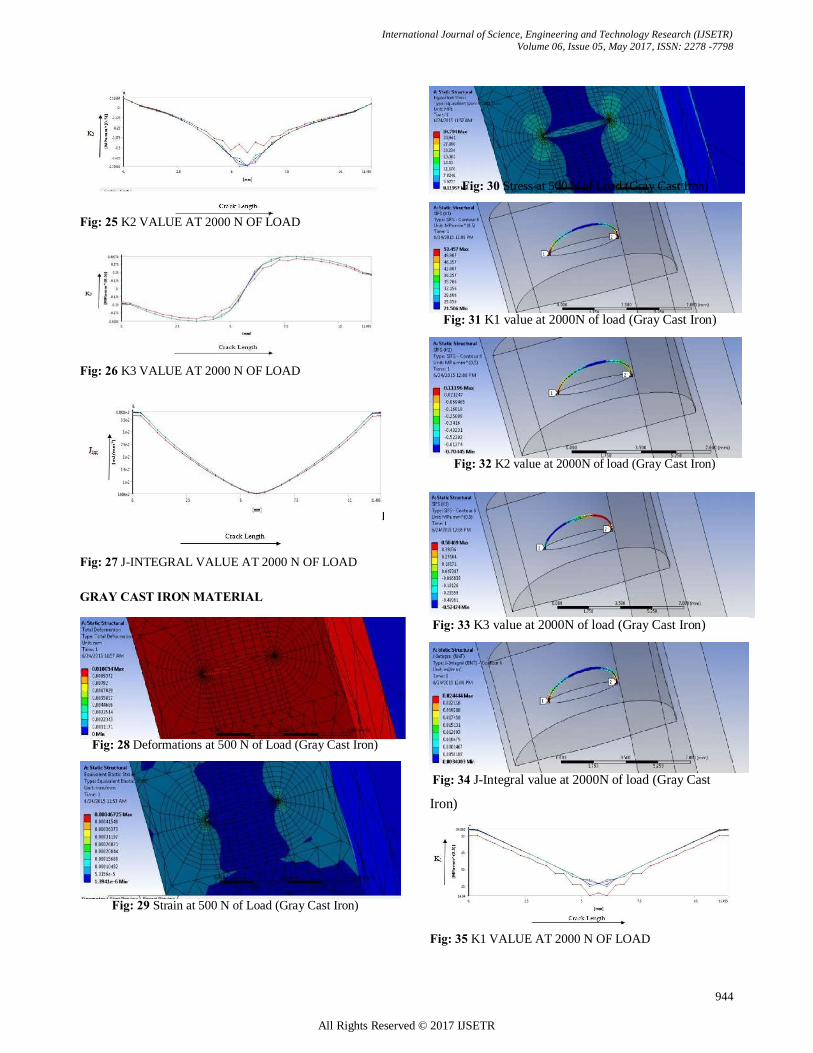
Fig: 47 K2 VALUE AT 2000 N OF LOAD
Fig: 48 K3 VALUE AT 2000 N OF LOAD Fig: 49 J-INTEGRAL VALUE AT 2000 N OF LOAD
RESULTS GRAPH REPRASENTING LOAD VS K1
Graph & Table 1 K1 values at Different Loads
of Different Materials GRAPH REPRASENTING LOAD VS K2 Graph & Table 2 K2 values at Different Loads
of Different Materials GRAPH REPRASENTING LOAD VS K3
Graph & Table 3 K3 values at Different Loads of Different Material

International Journal of Science, Engineering and Technology Research (IJSETR)
Volume 06, Issue 05, May 2017, ISSN: 2278 -7798
947
All Rights Reserved © 2017 IJSETR
GRAPH REPRASENTING LOAD VS J-INTEGRAL Graph & Table 4 J-Integral values at Different loads
of Different Materials CONCLUSION By investigation of the crack analysis done on completely
different materials I will conclude that by considering stress
intensity factors and J-integrals that Ti alloy has additional
withstanding capability wherever because the alternative
materials even have the potential of withstanding however
not the maximum amount as Ti alloy. In this work a trial has been created to seek out the method
of crack propagation and stress distribution during a typical
bracket region bracket by victimisation ANSYS and
CATIA. this sort of research is additional economic and time saving development and might be accustomed monitor
the cracks in numerous elements of region structures and
elements. The first step of the associate degreealysis consisted of
victimisation ANSYS to perform elastic stress analysis on
an un-cracked bracket to spot the high stress regions. In step 2, the un-cracked model was foreign to CATIA
associate degreed an initial crack of easy pure mathematics
was introduced and several other ANSYS files were created with crack. Step 3 of the analysis consists of victimisation
ANSYS to perform elastic stress analysis of the
antecedently cracked bracket created by ANSYS. For the model of cracks, the results show within the Mode I
stress intensity factors for the cracked model area unit
below the materials fracture toughness. Therefore, it seems that the bracket will tolerate little corner cracks within the
structure. The analysis procedure so are often accustomed
ceaselessly monitor the brackets and to require applicable
call on time of replacement of such brackets.
REFERENCES [[1] FRANC3D & ANSYS Tutorial. September 2010.
http://www.fracanalysis.com/Franc3D Documentation. [2] Honnorat, Yves. "Issues and breakthrough in manufacture of turbo engine titanium parts." Materials Science and Engineering, A213, 1996: 115-123. [3] J.P.Immarigeon, R.T.Holt, A.K. Koul, L.W.Zhao, Wallace and J.C. Beddoes , Lightweight Materials for Aircraft Applications, NRC Institute for Aerospace Research, 1995.
[4] Titanium. http://en.wikipedia.org/wiki/Titanium (accessed January 12, 2011). [5] Barsom, M. John, Rolfe and T. Stanley Fracture and Fatigue Control in Structures: Application of Fracture Mechanics, Philadelphia, 1999. [6] C.P.Paris, and G.C Sih, “Stress Analysis of Cracks,” in Fracture Toughness Testing and Its Applications, ASTM STP 381, American Society for Testing and Materials, Philadelphia, 1965. [7] B.J.Carter, P.A. Wawrzynek, and A.R.Ingraffea, Automated 3D Crack Growth Simulation, Cornell Fracture Group, 2003. BIOGRAPHIES
1. ................................................................................................................................... N
Nati Krishna kanth is currently pursuing master’s degree
program in CAD/CAM in KITS Engineering College,
Divili, Kakinada, Andhra Pradesh.
2. ................................................................................................................................... S
Sanmala. Rajasekhar is working as Associate Professor in
Mechanical Engineering KITS Engineering College, Divili,
Kakinada, Andhra Pradesh.