Embed Size (px)
Citation preview

ISSN: 2278 – 7798 International Journal of Science, Engineering and Technology Research (IJSETR)
Volume 5, Issue 4, April 2016
1098
ALL RIGHTS RESERVED © 2016 IJSETR
NON LINEAR STATIC STRESS ANALYSIS OF ZONED ROLLER COMPACTED
CONCRETE DAM USING FINITE ELEMENT METHOD
Birhane Gebreyohannes Hagos1, I. S.Parvathi
2, T.V. Praveen
3
Department of Civil Engineering, College of Engineering Andhra University (A), Visakhapatnam-530003, India
Abstract: - Modeling and analysis of huge and
complicated civil engineering structures like concrete
dams were not easy in the past time, since the
advancement of modern computers that can process large data; civil engineers become so familiar with
different civil engineering-related packages. This tool
can help to model and analysis of structures and can
save energy and time. Concrete dams, like a zoned
(with different grade of concrete) roller compacted
concrete gravity dams are not easy to compute by the
traditional method of analysis (conventional gravity
method). The most interesting focus of the present
study will be emphasized on the modeling and
analysis of the zoned RCC gravity dam. An interface
element is used to model the interaction between
zoned roller compacted concrete (RCC) gravity dam, foundation, and in between the different grade of
concrete strength. Before the analysis of the zoned
roller concrete gravity dam section, the dam is
analysed for different uniform grade of concrete
strengths separately using M7, M10, M12 and M15
respectively. At the change of grade of concrete and
between the bottom of the dam and the foundation,
an interface element is introduced. A maximum and
minimum principal stresses are computed at different
elevation starting from the bottom of the dam. In both
cases, the result from the analysis shows that the
stress concentration decreased from the bottom of the
dam to the top.
The dam is divided into four zones
according to the acceptable stress that can be carrying
by the specific grade of concrete strength of the dam.
Zone-1(M7) covers the top of the dam, zone-2(M10) top middle, zone-3(M12) bottom middle and zone-4
(M15) bottom of the dam section. As well, the
horizontal and vertical displacements are computed
for both cases, and a less displacement result is
observed from the case of zoned roller compacted
concrete (RCC) gravity dam than the uniformly
graded rollers compacted concrete gravity dam. The
overall analysis shows thatzonedRCC gravity dam
can give convenient and economical purposesthan
using uniform grade of section throughout the entire
section.
Key words: - Concrete Gravity Dams, Roller
Compacted Concrete Dams, Dam-Foundation
Interaction, Interface Elements, Finite Element
Analysis.
1. INTRODUCTION
The US Army Corps of Engineers (EM
1110-2-2200, 1995) states that a dam is a hydraulic
structure constructed across a river to store water on
its upstream side. It is an impervious or fairly
impervious barrier constructed across a natural
stream so that a reservoir is formed, which facilitates
in utilizing water when needed. A gravity dam is a
solid concrete or masonry structure which ensures stability against all applied loads by its weight alone
without depending on arch or beam action. Such
dams are usually straight in the plan and
approximately triangular in cross-section. The most
common classification of gravity dams is by the
materials composing the structure. Concrete dams
include mass concretedams made of
conventional,roller compacted concrete dams,
masonry dams, hollow gravity dams, reinforced
concrete dams and composite dams are a
combination of concrete and embankment dams
construction materials of composite dams are the
same used for concrete and embankment dams.
Roller Compacted Concrete Gravity Dam
ACI.207:5R-89(American concrete Institute)
standard defines,roller compacted concrete (RCC) as
concrete compacted by a roller compaction. The
concrete mixture in its unhardened state must support
a roller while being compacted. Thus RCC differs
from conventional concrete, principally in its
consistency requirement. For effective consolidation,
the concrete mixture must be dry enough to prevent
sinking of the vibratory roller equipment but wet
enough to permit adequate distribution of the binder
mortar in concrete during the mixing and vibratory compaction operations. The development of RCC
ISSN: 2278 – 7798 International Journal of Science, Engineering and Technology Research (IJSETR)
Volume 5, Issue 4, April 2016
1099
ALL RIGHTS RESERVED © 2016 IJSETR
caused a major shift in construction practices of mass
concrete dams and locks. The traditional method of
placing, compacting, and consolidation mass concrete
is at best at the slow process. Improvement in earth-
moving equipment made the construction of earth,
and rock filled dams speedier and cost effective. In
1970 California Professor Jerome Rafael, pointed out
that the fill materials have only 10% of cohesion of
mass concrete. The first successful application of RCC technology was demonstrated in 1974. The
repair of the collapsed intake tunnel of Tarbela dam
proved that the material has more than adequate
strength and durability.
Some of the prominent works attempted on RCC
theme by Hague, M.N. et al. [1989] reported
conceptive analysis of many inferior and marginal
aggregates, waste products, and other deleterious
materials which do not meet standards and
specification to be use in the manufacturing of roller
compacted concrete, pavement construction, RCC
containing marginal aggregates becoming cost
effective and competitive. Mechanically weak and
poorly graded materials can be used to manufacture
RCC of adequate strength for use in pavement
structures. Marginal quality aggregate require higher amount of cement to produce similar strength. Silt
content up to 10% in aggregate will improve
workability and compatibility of RCC. Where Fly ash
is locally available it can be used to replace cement
and fine aggregated in mix design and help gain in
strength and durability to RCC pavements. In all the
construction sites it’s difficult to arrange good quality
of material hence adjust in the mix proportion is best
approach to utilize the available resources to
minimize the cost impact and saving in natural
resources. Dolen [1991]reported interaction analysis of air
content and the freeze thaw (FT) durability of RCC
and reported that it is possible to entrain air in "more
workable" RCC mixtures withVebeconsistency times
ranging from approximately 5 to 35 seconds. Air
entrainment improves the workability of RCC
mixtures, resulting in lower Vebe consistency times
and reduced segregation.FTdurability of air entrained
RCC increased from 66 to up to 409 percent above
that of the no air entrained mixtures. Koji Sakai
[1993]examined the importance of finding alternate material for fly ash, as availability of fly ash in some
part of the world is really an issue. It is very difficult
to achieve high durable RCC and control of heat
generation in dam construction without fly ash. One
admixture that is replacing fly ash is granulated blast
furnace slag. Concrete with moderate low heat slag
cement can provide the same or better performance
as fly ash cement concrete by employing a rational
combination of fineness and slag content. Also, the
advantages of slag cement at longer ages were
confirmed study clarified that concrete made with
slag cement can be provided with the same or better
performance when compared with a 30% fly ash
cement concrete. Also, the advantages of slag cement at the longer ages were confirmed. NaderGhafoori
and YuzhengCai [1998]conducted experiments on
laboratorymade roller compacted concrete with
variouscombinations of cement (Type I and Type V
for sulfateresistant concrete), lignite dry bottom ash,
and crushed limestone coarse to determine the
suitability of use of bottom fly ash to manufacture
long term durability bottom ash roller compacted
concretes. Richard Gagne et al. [1999]highlights the
OPP fines (mining byproduct referred to as OPP fines
means Ore Pretreatment PlantFines) is a very
effective filler in RCC because its particlesize distribution is very similar to that of the cement.
Therefore, alarge proportion of the total fines content
(cement or fly ash) can be replaced by OPP fines
without significantly changing the workability of the
RCC. A simple mathematical model, based on the
results of the factorial analysis, is proposed to select
the total fines content, the OPP fines replacement
ratio, and the water/fines ratio of an RCC mixture as
a function of the required Vebe time (5 sec. to 60sec.)
and 91days compressive strength (5 to 25 MPa). The
OPP fines are a relatively inert material, and this had very little effect on heat generation during
hydration.Wilson and Turcotte (1986) present the
exact solution of the equations of elasticity for elastic
half-plane subjected to an arbitrary set of surface
loads. This solution leads to the calculation of
flexibility and stiffness matrices which relate
concentrated loads and the corresponding
displacements. This model was only valid for
homogeneous foundation. Yahui and Guowei (1995)
introduced the constitutive model for isotropic
material to simulate both elastic and elastoplastic
behavior of RCC body. In addition, an interface element was used to model lift joint of RCC dam.
This method is difficult and not practical due to
required number of interface elements for modeling
all the lift joints in the high RCC dams.

ISSN: 2278 – 7798 International Journal of Science, Engineering and Technology Research (IJSETR)
Volume 5, Issue 4, April 2016
1100
ALL RIGHTS RESERVED © 2016 IJSETR
2. MODELING AND METHODOLOGY
2.1 Finite Element Method Analysis Using
SAP2000:
The finite-element method is a general
numerical method for obtaining an approximate
solution of various boundary value and initial value problems. In this method, the analysis domain is
divided into a combination of regular shaped finite
elements connected at a limited number of nodes.
The governing differential equation is then integrated
over the finite-element domains and summed to
obtain a set of linear simultaneous algebraic
equations in terms of variables defined at nodes.
The SAP2000 graphic user interface (GUI)
is used to model, analyze, design, and display the
structure geometry, properties and analysis results.
The fundamental equations of structural mechanics
can be placed into three categories. (I)the stress-strain
relationship contain the material property information
that must be evaluated by laboratory or field
experiments. II)The total structure, each element, and each infinitesimal particle within each element must
be in force equilibrium in their deformed position.
III)Displacement compatibility conditions must be
satisfied. If all three equations are satisfied for all
points in time other conditions will automatically be
satisfied.
2.2. Finite-Element Model of Dam-Foundation
Interface and Computation of Stiffness Values:
At the intersection of the upstream (or
downstream) face of the dam with the foundation, a
stress concentration exists. A fine mesh solution, for
any load condition, would probably indicate very
large stresses. A further refinement of the mesh
would just produce higher stresses. However, due to
the nonlinear behavior of both the concrete and
foundation material, these high stresses cannot exist
in the actual structure. Hence, it is necessary to select
a finite-element model that predicts the overall
behavior to the structure without indicating a high-stress concentration that cannot exist in the actual
structure. In our case, an interface element is
introduced for both the dam-foundation and in
between the different material properties.
In order to obtain the best accuracy regular
quadrilateral types of meshes are used. Two nodes
are used at all interfaces between two different
material properties. This is because the stresses
parallel with the interface of different materials are
not equal. Therefore, two nodes on the interface are
required in order for SAP2000 to plot accurate stress
contours. Normal hydrostatic loading is often directly
applied at the top to the foundation and the upstream
face of the dam. If this type of surface loading is
applied, large horizontal tension stresses will exist in
the foundations and vertical tensile stresses will exist
at the upstream surface at the dam. In other words, the surface hydrostatic loading tends to tear the dam
from the foundation. The purpose of non-linear gap
element is to force surfaces within the computational
model to transfer compression forces only and not
allow tension forces to develop when the surfaces are
not in contact. This can be accomplished by
connecting nodes on two surfaces, located at the
same point in space, with a gap element normal to the
surface. The axial stiffness should be selected huge
enough to transfer compression forces across the gap
with the minimum of deformation within the gap
element compared the stiffness of the nodes on the surface. If the gap stiffness is too large, however,
numerical problems can develop in the solution
phase.
The approximate surface node stiffness can be calculated using (the theory of elasticity) from the
following simple equation.
𝑘 = 𝐴 ∗𝐸
𝑡
Where A, is the approximate surface area associated with the normal gap element, E is the modulus of
elasticity of the dam, and t is the finite-element
dimension normal at the surface. The gap element
stiffness is taken as 1000 times stiffer than the
surface node. Hence:
𝑘g = 1000𝐴 ∗ 𝐸/𝑡
2. 3.3. Validation of the Modeling Procedure
2.3.1. Validation of SAP2000 Program
For validation purpose a 100 m height and
100 m base width of the triangular concrete dam are
modeled using NISA (Numerically Integrated
element for System Analysis) commercially available
package and stresses in the upstream and downstream
are computed. Similarly with the same model, finite element analysis using SAP2000 is carried out by 4
nodded isoperimetric elements. A total 216 elements,

ISSN: 2278 – 7798 International Journal of Science, Engineering and Technology Research (IJSETR)
Volume 5, Issue 4, April 2016
1101
ALL RIGHTS RESERVED © 2016 IJSETR
84 elements within the dam body and 132 in the
foundation are used. The foundation is fixed to its
base, and translation is allowed in the z-direction, and
translation is restrained for x-direction and y-
direction. Validation of the program is carried out for
two cases, i.e., with and without interface elements
between dam and foundation, and the stress results
are verified. The bottom of the foundation is
considered as having a fixed end support and the upstream and downstream adjacent sides restrained
not to translate to x and y direction and is free to
translate in the z-direction. Then the values of the
stresses are compared, and similar results are found
from the two packages. As a result, the modeling of
the case study (Gibe-III) is computed using
SAP2000. Fig.1 shows the Discretization of FEM
model.
Fig. 1 discretization for validation
Computation of Stresses using NISA and SAP2000
The horizontal and vertical stresses in the
upstream and downstream are computed using the
two commercially available FE packages. The
stresses are computed for two cases
1. Without the interface element in the dam-
foundation contacts.
2. With interface elements in the dam-
foundation contacts.
The material properties considered for the
validation are shown in Table 1. The computations of
the stress for the two-cases are carried out and
presented in the tabular form as shown in Table2 and
Table 3. Table 2 shows computation of stresses
within the dam without interface elements in the
dam-foundation. Table3 show the comparison of
stress variation at heel and toe of the dam due to self-
weight with interface elements are presented. The
results are compared with those obtained by SAP
with NISA and are found to be satisfactory.
Table 1 Properties of materials used in the model
material
fck
(MPa)
Material
density
(kg/m3)
Young’s
modulus,
E (MPa)
Poison’s
ratio
υ
concrete 20 24 22000 0.15
foundation
24 30000 0.15
Table 2 NISA VS SAP2000 results without interface
element in the dam-foundation interface (MPa)
Without interface element
SAP NISA
SXX SYY SXY SXX SYY SXY
Heel -1.08 -2.51 1.08 -1.10 -2.55 1.12
Toe -0.404 -0.198 0.208 -0.402 -0.202 0.202
Table 3 NISA VS SAP2000 stress results with interface element in the dam-foundation interface
(MPa)
With interface element
SAP NISA
SXX SYY SXY SXX SYY SXY
Heel Concrete -1.2 -3.8 0.6 -1.2 -3.8 0.64
Rock -1.15 -1.7 0.34 -1.16 1.70 0.30
Toe Concrete -0.29 -0.3 0.24 -0.18 0.29 0.26
Rock -0.34 0.38 0.94 -0.34 0.31 0.15
3. Details of the present case Study (Gibe-III
RCC Gravity dam)
The present study is carried out on Gibe-III RCC
gravity dam as a case study. Gibe-III dam is 243 m
ISSN: 2278 – 7798 International Journal of Science, Engineering and Technology Research (IJSETR)
Volume 5, Issue 4, April 2016
1102
ALL RIGHTS RESERVED © 2016 IJSETR
high RCC concrete dam along with the crest gates
and semi- underground power station on the right
bank of the dam. The dam is located Omo-gibe River
in Ethiopia. The Gibe-III dam is designed as a
massive straight gravity type dam, constructed with
roller compacted concrete. The maximum height of
the dam above the deepest foundation level is 214 m
for non-overflow section and its full reservoir level at
243 m. The total length of Gibe-III at its top is 610 m. In Gibe-III dam the rock formation belongs to
partly weathered Trachyte/SW-T) along rock
foundation and slightly altered trachyte (SA-T) in the
right abutments. For the present study, the non-
overflow section is considered to carry out stress
analysis for finding the stresses at the different zone
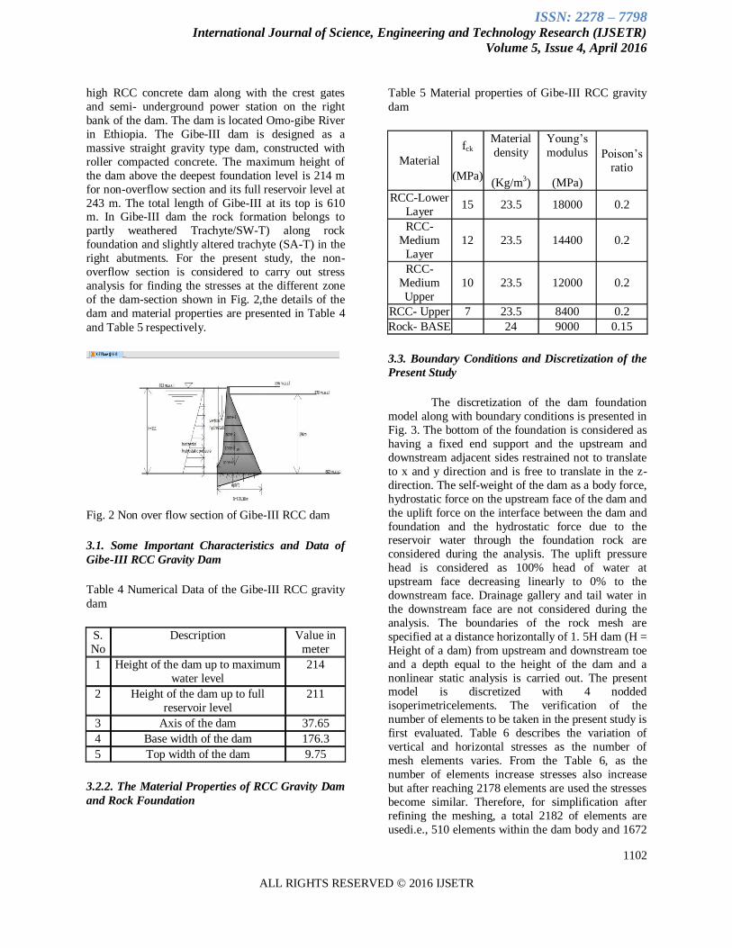
of the dam-section shown in Fig. 2,the details of the
dam and material properties are presented in Table 4
and Table 5 respectively.
Fig. 2 Non over flow section of Gibe-III RCC dam
3.1. Some Important Characteristics and Data of
Gibe-III RCC Gravity Dam
Table 4 Numerical Data of the Gibe-III RCC gravity
dam
S.
No
Description Value in
meter
1 Height of the dam up to maximum
water level
214
2 Height of the dam up to full
reservoir level
211
3 Axis of the dam 37.65
4 Base width of the dam 176.3
5 Top width of the dam 9.75
3.2.2. The Material Properties of RCC Gravity Dam
and Rock Foundation
Table 5 Material properties of Gibe-III RCC gravity
dam
Material
fck
(MPa)
Material
density
(Kg/m3)
Young’s
modulus
(MPa)
Poison’s
ratio
RCC-Lower
Layer 15 23.5 18000 0.2
RCC-
Medium
Layer
12 23.5 14400 0.2
RCC-
Medium
Upper
10 23.5 12000 0.2
RCC- Upper 7 23.5 8400 0.2
Rock- BASE
24 9000 0.15
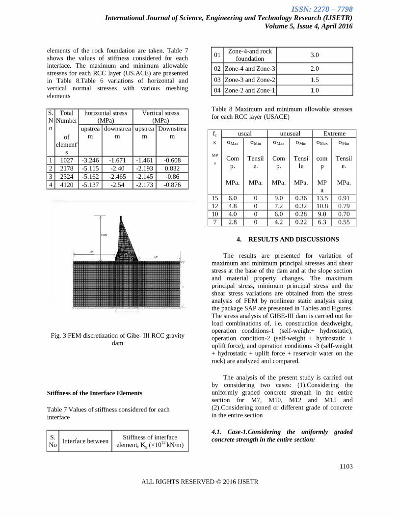
3.3. Boundary Conditions and Discretization of the
Present Study
The discretization of the dam foundation
model along with boundary conditions is presented in
Fig. 3. The bottom of the foundation is considered as
having a fixed end support and the upstream and
downstream adjacent sides restrained not to translate
to x and y direction and is free to translate in the z-
direction. The self-weight of the dam as a body force,
hydrostatic force on the upstream face of the dam and
the uplift force on the interface between the dam and
foundation and the hydrostatic force due to the reservoir water through the foundation rock are
considered during the analysis. The uplift pressure
head is considered as 100% head of water at
upstream face decreasing linearly to 0% to the
downstream face. Drainage gallery and tail water in
the downstream face are not considered during the
analysis. The boundaries of the rock mesh are
specified at a distance horizontally of 1. 5H dam (H =
Height of a dam) from upstream and downstream toe
and a depth equal to the height of the dam and a
nonlinear static analysis is carried out. The present model is discretized with 4 nodded
isoperimetricelements. The verification of the
number of elements to be taken in the present study is
first evaluated. Table 6 describes the variation of
vertical and horizontal stresses as the number of
mesh elements varies. From the Table 6, as the
number of elements increase stresses also increase
but after reaching 2178 elements are used the stresses
become similar. Therefore, for simplification after
refining the meshing, a total 2182 of elements are
usedi.e., 510 elements within the dam body and 1672
ISSN: 2278 – 7798 International Journal of Science, Engineering and Technology Research (IJSETR)
Volume 5, Issue 4, April 2016
1103
ALL RIGHTS RESERVED © 2016 IJSETR
elements of the rock foundation are taken. Table 7
shows the values of stiffness considered for each
interface. The maximum and minimum allowable
stresses for each RCC layer (US.ACE) are presented
in Table 8.Table 6 variations of horizontal and
vertical normal stresses with various meshing
elements
S.
N
o
Total
Number
of
element'
s
horizontal stress
(MPa)
Vertical stress
(MPa)
upstrea
m
downstrea
m
upstrea
m
Downstrea
m
1 1027 -3.246 -1.671 -1.461 -0.608
2 2178 -5.115 -2.40 -2.193 0.832
3 2324 -5.162 -2.465 -2.145 -0.86
4 4120 -5.137 -2.54 -2.173 -0.876
Fig. 3 FEM discretization of Gibe- III RCC gravity
dam
Stiffness of the Interface Elements
Table 7 Values of stiffness considered for each
interface
S.
No Interface between
Stiffness of interface
element, Kg (×1012 kN/m)
01 Zone-4-and rock
foundation 3.0
02 Zone-4 and Zone-3 2.0
03 Zone-3 and Zone-2 1.5
04 Zone-2 and Zone-1 1.0
Table 8 Maximum and minimum allowable stresses
for each RCC layer (USACE)
fc
K
MP
a
usual unusual Extreme
σMax
Com
p.
MPa.
σMin
Tensil
e.
MPa.
σMax
Com
p.
MPa.
σMin
Tensi
le
MPa.
σMax
com
p
MP
a
σMin
Tensil
e.
MPa.
15 6.0 0 9.0 0.36 13.5 0.91
12 4.8 0 7.2 0.32 10.8 0.79
10 4.0 0 6.0 0.28 9.0 0.70
7 2.8 0 4.2 0.22 6.3 0.55
4. RESULTS AND DISCUSSIONS
The results are presented for variation of
maximum and minimum principal stresses and shear
stress at the base of the dam and at the slope section
and material property changes. The maximum
principal stress, minimum principal stress and the
shear stress variations are obtained from the stress
analysis of FEM by nonlinear static analysis using
the package SAP are presented in Tables and Figures.
The stress analysis of GIBE-III dam is carried out for
load combinations of, i.e. construction deadweight, operation conditions-1 (self-weight+ hydrostatic),
operation condition-2 (self-weight + hydrostatic +
uplift force), and operation conditions -3 (self-weight
+ hydrostatic + uplift force + reservoir water on the
rock) are analyzed and compared.
The analysis of the present study is carried out
by considering two cases: (1).Considering the
uniformly graded concrete strength in the entire
section for M7, M10, M12 and M15 and
(2).Considering zoned or different grade of concrete
in the entire section
4.1. Case-1.Considering the uniformly graded
concrete strength in the entire section:
ISSN: 2278 – 7798 International Journal of Science, Engineering and Technology Research (IJSETR)
Volume 5, Issue 4, April 2016
1104
ALL RIGHTS RESERVED © 2016 IJSETR
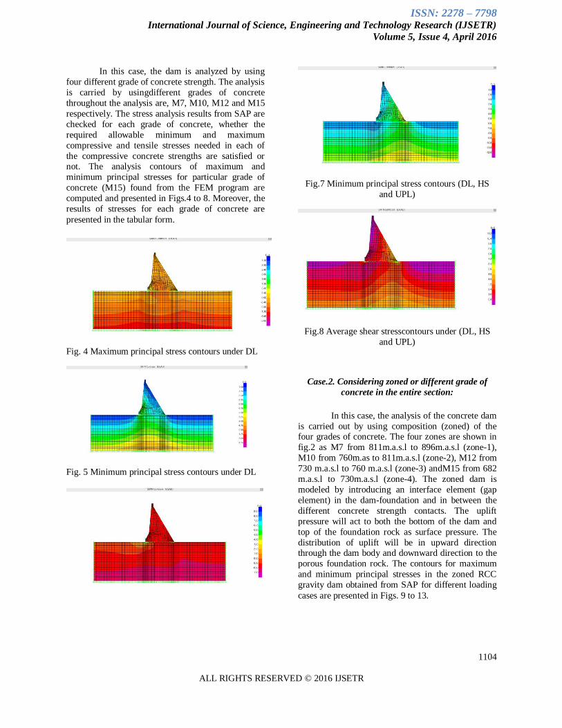
In this case, the dam is analyzed by using
four different grade of concrete strength. The analysis
is carried by usingdifferent grades of concrete
throughout the analysis are, M7, M10, M12 and M15
respectively. The stress analysis results from SAP are
checked for each grade of concrete, whether the
required allowable minimum and maximum
compressive and tensile stresses needed in each of
the compressive concrete strengths are satisfied or not. The analysis contours of maximum and
minimum principal stresses for particular grade of
concrete (M15) found from the FEM program are
computed and presented in Figs.4 to 8. Moreover, the
results of stresses for each grade of concrete are
presented in the tabular form.
Fig. 4 Maximum principal stress contours under DL
Fig. 5 Minimum principal stress contours under DL
Fig.7 Minimum principal stress contours (DL, HS
and UPL)
Fig.8 Average shear stresscontours under (DL, HS
and UPL)
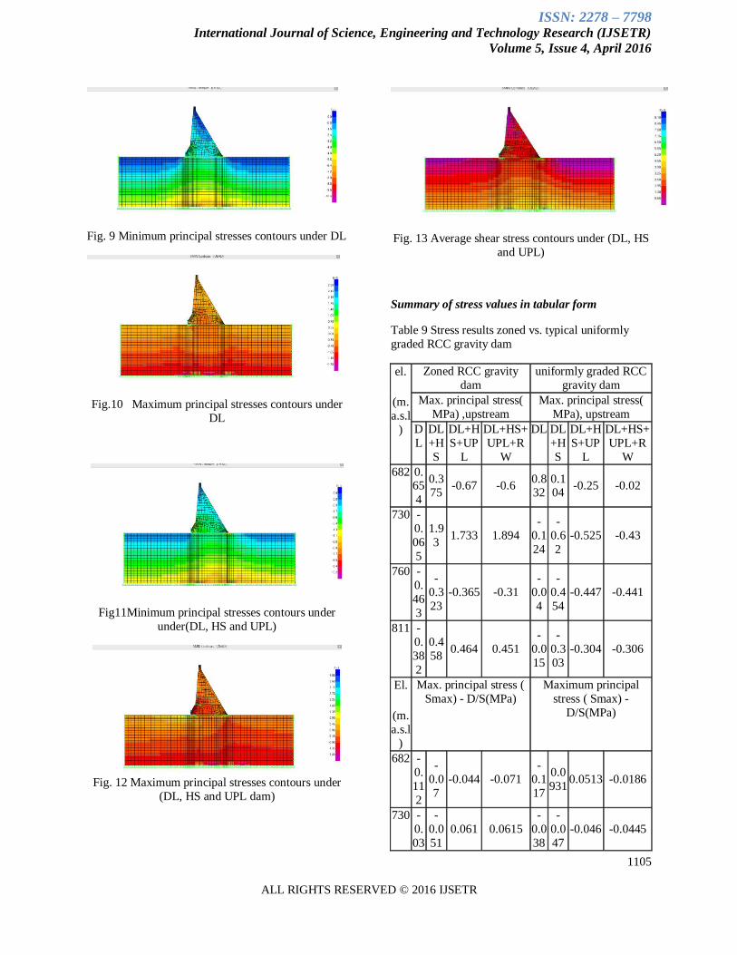
Case.2. Considering zoned or different grade of
concrete in the entire section:
In this case, the analysis of the concrete dam
is carried out by using composition (zoned) of the four grades of concrete. The four zones are shown in
fig.2 as M7 from 811m.a.s.l to 896m.a.s.l (zone-1),
M10 from 760m.as to 811m.a.s.l (zone-2), M12 from
730 m.a.s.l to 760 m.a.s.l (zone-3) andM15 from 682
m.a.s.l to 730m.a.s.l (zone-4). The zoned dam is
modeled by introducing an interface element (gap
element) in the dam-foundation and in between the
different concrete strength contacts. The uplift
pressure will act to both the bottom of the dam and
top of the foundation rock as surface pressure. The
distribution of uplift will be in upward direction through the dam body and downward direction to the
porous foundation rock. The contours for maximum
and minimum principal stresses in the zoned RCC
gravity dam obtained from SAP for different loading
cases are presented in Figs. 9 to 13.
ISSN: 2278 – 7798 International Journal of Science, Engineering and Technology Research (IJSETR)
Volume 5, Issue 4, April 2016
1105
ALL RIGHTS RESERVED © 2016 IJSETR
Fig. 9 Minimum principal stresses contours under DL
Fig.10 Maximum principal stresses contours under
DL
Fig11Minimum principal stresses contours under
under(DL, HS and UPL)
Fig. 12 Maximum principal stresses contours under
(DL, HS and UPL dam)
Fig. 13 Average shear stress contours under (DL, HS
and UPL)
Summary of stress values in tabular form
Table 9 Stress results zoned vs. typical uniformly
graded RCC gravity dam
el.
(m.
a.s.l
)
Zoned RCC gravity
dam
uniformly graded RCC
gravity dam
Max. principal stress(
MPa) ,upstream
Max. principal stress(
MPa), upstream
D
L
DL
+H
S
DL+H
S+UP
L
DL+HS+
UPL+R
W
DL DL
+H
S
DL+H
S+UP
L
DL+HS+
UPL+R
W
682 0.65
4
0.375
-0.67 -0.6 0.832
0.104
-0.25 -0.02
730 -
0.
06
5
1.9
3 1.733 1.894
-
0.1
24
-
0.6
2
-0.525 -0.43
760 -
0.
46
3
-
0.3
23
-0.365 -0.31
-
0.0
4
-
0.4
54
-0.447 -0.441
811 -
0.
38
2
0.4
58 0.464 0.451
-
0.0
15
-
0.3
03
-0.304 -0.306
El.
(m.
a.s.l
)
Max. principal stress (
Smax) - D/S(MPa)
Maximum principal
stress ( Smax) -
D/S(MPa)
682 -
0.
11
2
-
0.0
7
-0.044 -0.071
-
0.1
17
0.0
931 0.0513 -0.0186
730 -
0.
03
-
0.0
51
0.061 0.0615
-
0.0
38
-
0.0
47
-0.046 -0.0445

ISSN: 2278 – 7798 International Journal of Science, Engineering and Technology Research (IJSETR)
Volume 5, Issue 4, April 2016
1106
ALL RIGHTS RESERVED © 2016 IJSETR
7 8
760 -
0.
028
0.0
382 0.034 0.037
-
0.0
651
-
0.0
68
-0.066 -0.065
811 -0.
04
7
0.0
94 -0.1 0.093
-0.0
48
4
-0.0
72
-0.071 -0.0704
El.
(m.
a.s.l)
Minimum principal
stress ( Smax) -
U/S(MPa)
Minimum principal
stresses (Smin)-
U/S(MPa) ,
682 -0.
11
2
-
0.0
7
-0.044 -0.071
-
1.2
2
-
1.3
7
-2.717 -2.791
730 -
0.
03
7
-
0.0
51
0.061 0.0615
-
5.5
6
-
1.6
7
-1.621 -1.6
760 -
0.
02
8
0.0
382 0.034 0.037
-
2.9
3
-
1.3
37
-1.338 -1.339
811 -
0.
04
7
0.0
94 -0.1 0.093
-
1.9
73
-
0.9
47
-0.948 -0.949
El.
(m.
a.s.l
)
Minimum principal
stress ( Smax) -
D/S(MPa)
Minimum principal
stresses (Smin)-
D/S(MPa) ,
682 -
0.
92
-
1.9
4
-2.551 -2.54
-
2.8
88
-
9.3
1
-8.91 -7.95
730 -
3.
35
5
-
1.4
5
-1.5 -1.45
-
1.5
53
-
4.9
53
-4.722 -4.457
760 -
2.26
7
-
1.59
-1.664 -1.543
-
0.894
-
3.875
-3.78 -3.68
811 -
2.
14
-
0.5
32
-0.528 -0.532
-
0.4
27
-
2.5
55
-2.556 -2.557.
4.2.Graphical Representation Uniform graded
Compressive Strength (M7, M10, and M12&M15)
versus Zoned RCC gravity dam.
The stress analysis of GIBE-III dam is
carried out for load combinations of, i.e.
Construction-1-(dead-weight), operation condition-2-
(self-weight+ hydrostatic), operation condition-3-
(self-weight + hydrostatic +uplift force) and
operation conditions-4-(self-weight +hydrostatic+
uplift force+ reservoir water to the rock) are analyzed
and compared. The variation of maximum and
minimum principal stresses and shear stress at the base of the dam and at section corresponding to
upstream slope change point and change of section
properties of the dam section will be analyzed using
load combination are presented below.
Summary charts of minimum and maximum
principal stress results in the upstream and
downstream faces for different loading cases.
Fig.14 Variation of maximum principal stress results in the downstream face for zoned VS uniform graded RCC
Fig.15 Variation of maximum principal stress results
in the downstream face for zoned VS Uniform graded
RCC gravity dam
-10
-8
-6
-4
-2
0
dl
hs+
dl+
up
l
dl
hs+
dl+
up
l
dl
hs+
dl+
up
l
dl
hs+
dl+
up
l
dl
hs+
dl+
up
l
fck-7m
pa
fck-10
mpa
fck-12
mpa
fck-15
mpa
zoned
Min
imu
m p
rin
cip
al s
tres
s in
mil
lion
Minimum principal stress in the
downstream faceElevati
on
(682m.
a.s.l)
Elevati
on
(730m.
a.s.l)
Elevati
on
(760m.
a.s.l)
Elevati
on
811m.a
.s.l

ISSN: 2278 – 7798 International Journal of Science, Engineering and Technology Research (IJSETR)
Volume 5, Issue 4, April 2016
1107
ALL RIGHTS RESERVED © 2016 IJSETR
-0.3
-0.2
-0.1
0
0.1
0.2
0.3
0.4
0.5
dl
hs+
dl+
up
l
dl
hs+
dl+
up
l
dl
hs+
dl+
up
l
dl
hs+
dl+
up
l
dl
hs+
dl+
up
l
fck-7mpa
fck-10mpa
fck-12mpa
fck-15mpa
zoned
Max
imu
m p
rin
cip
al s
tres
s in
MP
a
Maximum principal stress in the
downstream face
Elev
ation
(682
m.a.s.l)
Elev
ation
(730
m.a.s.l)
Elev
ation
(760
m.a.s.l)
Elev
ation
811
m.a.s.l
Fig.16 Variation of minimum principal stress results
in the upstream face for zoned vs. uniform graded
RCC gravity dam
Fig.17 Variation of maximum principal stress (major) results in the upstream face for zoned VS uniform graded
RCC gravity dam
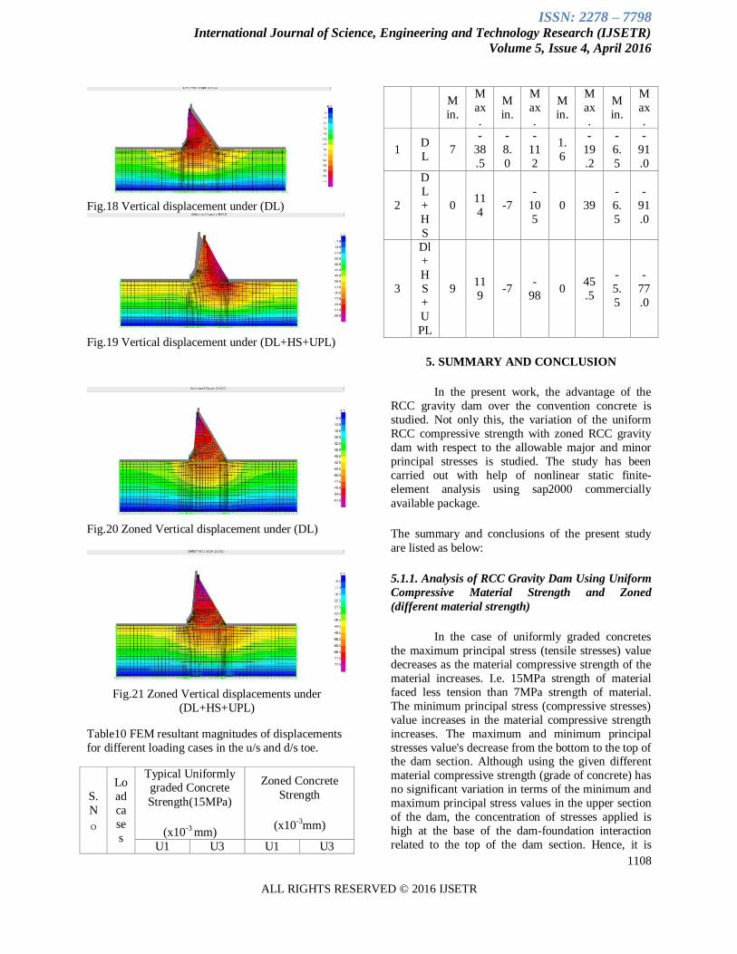
4.3. Displacements
The detailed results of displacement's analysis
obtained by FEM for both zoned and uniform
concrete strength are given below in the forms of
figures and tables. The figures and the tables summarize the minimum and maximum of horizontal
and vertical displacements in both cases Maps
showing horizontal and vertical displacements
varying with the loading condition of the non over
flow section in zoned and uniform typical concrete
strength are computed.
The displacements are computed for two cases: - (1).
Considering uniformly graded concrete strength and
(2).Considering composite (zoned) concrete
strengths. The contours of the case -1 and case -2 are
arranged in Fig.4.16, 4.17, and Fig. 4.18, 4.19,
respectively.
-6
-5
-4
-3
-2
-1
0
dl
hs+
dl+
up
l
dl
hs+
dl+
up
l
dl
hs+
dl+
up
l
dl
hs+
dl+
up
l
dl
hs+
dl+
up
l
fck-7mpa
fck-10mpa
fck-12mpa
fck-15mpa
zoned
Min
imum
pri
nci
pal
str
ess
in M
Pa
Minimum principal stress in the upstream
faceEleva
tion
(682
m.a.s
.l)
Eleva
tion
(730
m.a.s
.l)
Eleva
tion
(760
m.a.s
.l)
Eleva
tion
811m
.a.s.l
-1.5
-1
-0.5
0
0.5
1
1.5
2
2.5
dl
hs+
dl+
up
l
dl
hs+
dl+
up
l
dl
hs+
dl+
up
l
dl
hs+
dl+
up
l
dl
hs+
dl+
up
l
fck-7mpa
fck-10mpa
fck-12mpa
fck-15mpa
zoned
Max
imum
pri
nci
pal
str
ess
in M
Pa
Maximum principal stress in the
upstream faceEle
vati
on
(682m.
a.s.l
)
Ele
vati
on
(730m.
a.s.l
)
Ele
vati
on
(760m.
a.s.l
)
Ele
vati
on
811m.a.
s.l
ISSN: 2278 – 7798 International Journal of Science, Engineering and Technology Research (IJSETR)
Volume 5, Issue 4, April 2016
1108
ALL RIGHTS RESERVED © 2016 IJSETR
Fig.18 Vertical displacement under (DL)
Fig.19 Vertical displacement under (DL+HS+UPL)
Fig.20 Zoned Vertical displacement under (DL)
Fig.21 Zoned Vertical displacements under
(DL+HS+UPL)
Table10 FEM resultant magnitudes of displacements
for different loading cases in the u/s and d/s toe.
S.
N
O
Lo
ad
ca
se
s
Typical Uniformly
graded Concrete
Strength(15MPa)
(x10-3 mm)
Zoned Concrete
Strength
(x10-3mm)
U1 U3 U1 U3
M
in.
M
ax
.
M
in.
M
ax
.
M
in.
M
ax
.
M
in.
M
ax
.
1 D
L 7
-
38
.5
-
8.
0
-
11
2
1.
6
-
19
.2
-
6.
5
-
91
.0
2
D
L
+
H
S
0 11
4 -7
-
10
5
0 39
-
6.
5
-
91
.0
3
Dl
+
H
S
+
U
PL
9 11
9 -7
-
98 0
45
.5
-
5.
5
-
77
.0
5. SUMMARY AND CONCLUSION
In the present work, the advantage of the
RCC gravity dam over the convention concrete is
studied. Not only this, the variation of the uniform
RCC compressive strength with zoned RCC gravity
dam with respect to the allowable major and minor
principal stresses is studied. The study has been
carried out with help of nonlinear static finite-
element analysis using sap2000 commercially
available package.
The summary and conclusions of the present study
are listed as below:
5.1.1. Analysis of RCC Gravity Dam Using Uniform
Compressive Material Strength and Zoned
(different material strength)
In the case of uniformly graded concretes
the maximum principal stress (tensile stresses) value
decreases as the material compressive strength of the
material increases. I.e. 15MPa strength of material
faced less tension than 7MPa strength of material.
The minimum principal stress (compressive stresses)
value increases in the material compressive strength
increases. The maximum and minimum principal
stresses value's decrease from the bottom to the top of the dam section. Although using the given different
material compressive strength (grade of concrete) has
no significant variation in terms of the minimum and
maximum principal stress values in the upper section
of the dam, the concentration of stresses applied is
high at the base of the dam-foundation interaction
related to the top of the dam section. Hence, it is

ISSN: 2278 – 7798 International Journal of Science, Engineering and Technology Research (IJSETR)
Volume 5, Issue 4, April 2016
1109
ALL RIGHTS RESERVED © 2016 IJSETR
advisable to use a material having more strength at
the bottom of the dam section and less material
strength at the top section up to the minimum
requirement of the concrete material is satisfied.
In the case of zoned RCC gravity dam with
interface elements applied at the contact dam-
foundation are including and at the contact of each
material strength variation gives the more reliable
results than that of uniform material strength. The
constructing and designing of the zoned RCC gravity
dam is more economical than the uniform concrete
strength. In the upstream face wherea change of slope
and material is occurred at elevation of 730m.a.s.l, some high tension is occurred and a modification of
material compressive strength higher than the current
value may decrease the tension developed. From this
study designing and construction of the RCC gravity
dam can save both time and money than using the
conventional mass concrete and uniformly graded
concretes. Analyzing and designing of RCC gravity
dam using different strength of materials at the
different level of the section with interface elements
at the contact of material variation will decrease the
horizontal and vertical displacements that can occur
in the entire section through the dam.
List of Reference
1. Dolen, T. P., Freezing and Thawing
Durability of Roller-Compacted Concrete,
Durability of Concrete, Second
CANMET/ACI International Conference,
SP-126, V. M. Malhotra, ed., American
Concrete Institute, Farmington Hills, Mich, 1991, pp. 101-113.
2. Dolen, Timothy P., and Tayabji, Shiraz D.
1988. ―Bond Strength of Roller Compacted
Concrete,‖ Proceedings, Roller
3. E. K. Schrader, ‖ Compaction of Roller
Compacted Concrete, SP96-06, January 1,
1987, Special Publication, ACI special
Publication, Volume 96.
4. EEPCO, Gibe III, Level 1 Design, ―321
GEN R SP RMK 001 A, Dam foundations
geotechnical report –July 2008," Studio
Pietrangeli, Salini Costruttori 5. Federal Energy Regulatory Commission,
―Engineering guidelines on the evaluation of
the hydropower project – part 3: Gravity
dams," 2002
6. Felippa, C. A., ―Refined Finite Element of
Linear and Nonlinear Two- Dimensional
Solids," UCB/SESM Report No. 66/22,
University of California, Berkeley, October
1966.
7. Finite-Element Method," Prc. Symp. On Use
of Computers in Civil Engineering, Lisbon,
Portugal, 1962. Also, RILIM Bull., No. 19,
June 1963.
8. Howard B. Wilson, Louis H. Turcotte,
technical report ATC-86-1 on foundation
interaction problems involving an elastic, half-plane, 1986
9. J march and R.Gagne, E Ouellette and
S.Lepage, ‖ Mixture Proportioning of
―Roller Compacted Concrete-A review
Document, SP171-22, Special, Publication,
Volume 717, pp. 459-474.
10. J. Marchland, R. Gagne, E. Ouellette and S.
Lepage, Mixture Proportioning of Roller
Compacted Concrete-A Review, ACI
Special Publication, Volume -171, August 1,
1997
11. Jerry Foster and Wayne Jones, U.S.ACE Washington DC, technical report ITL-9.4-5,
July 1994.
12. Koji Sakai, Properties of Roller Compacted
Dam Concrete with Blended Cement
Containing Slag, SP141-08, ACI Special
publication, Volume –141, December 1,
1993
13. M. R. H. Dunston. Future Trends in Roller
Compacted Concrete Dam Construction,
ACI Special publication, Volume 144,
March 1994 14. M.N. Hague and M.A.Ward ―Marginal
Materials in roller compacted concrete in
pavement construction ―may –June 1987
ACI Journal received by 1,feeble 1987.
15. Nader Ghafoori and Zhiwang Zhang, ACI
Materials Journal/July-August 1998, Title
no. 95-M32, .pp2-4.
16. Nader Ghafooriand
YuzhengCai―Laboratory-Made Roller
Compacted Concretes Containing Dry
Bottom Ash: Part II—Long-Term
Durability, ACI Materials Journal, V. 95, No. 3, May -June 1998.pp 4-5
17. Richard E. Miller, Jr., Neil A. Cumming,
Glen A. Hairbrush Celik H. Ozyildirim,
Timothy P. Dolen Richard Gagne, Danielle
Martin, Francine A. Blais, Alain Prezeau
and Salsutio Guzman―The Use of a Finely-
Divided Mining By-Product in RCC for
Dam Construction‖ , SP172-06, 172,
December 1, 1999, Special Publication.pp4-
5.

ISSN: 2278 – 7798 International Journal of Science, Engineering and Technology Research (IJSETR)
Volume 5, Issue 4, April 2016
1110
ALL RIGHTS RESERVED © 2016 IJSETR
18. Schrader, Ernest K. 1988. ―Behavior of
Completed RCC Dams,‖ Proceedings,
Roller Compacted Concrete II Conference,
ASCE, New York, NY, 76-91.
19. Schrader, Ernest, and Stefanakos, John.
1995. ―Roller Compacted Concrete
Cavitation and Erosion Resistance,
"Proceedings. International Symposium on
Roller Compacted Concrete Dams, 1175-1188.
20. United States Bureau of reclamation,
―Design of small dams," 2006.
21. United States Department of the Interior
Bureau of Reclamation, Design of Gravity
Dams, 1976
22. US Army Corps of Engineers, ―Gravity dam
design," EM 1110-2-2200, 1995
23. Yahui, D., Guowei, L. (1995): Study on
failure mechanism of roller compacted
concrete gravity dam, Journal of Hydraulic
Engineering (in Chi nese), 5, pp. 55-59.
Symbols:
DL=DEAD LOAD
HS=HYDROSTATIC
UPL=UPLIFT
RW=RESERVOIR WATER
M7, 10, 12&15= GRADE OF CONCRETE STRENGTH IN MPa
MPa= MEGA PASCAL (1*10^6)
U1= HORIZONTAL DEFLECTION/DISPLACEMENT/
U3= VERTICAL DEFLECTION/DISPLACEMENT/