Embed Size (px)
Citation preview
Investigation of Dispersion of Nano-Graphite Particles in
Polyamide using SEM & XRD
Dr. Aravind K. U1
1. Professor & Head, Department of Mechanical Engineering, East West College of Engineering
ABSTRACT
The purpose of investigation is to understand dispersion of graphite reinforced polyamide
composites. The test was conducted as per design of experiment using pin-on-disc wear tester.
Researchers have studied wear mechanism of nano-graphite in polyamide. The dispersion of the
graphite particles were studied using SEM and XRD. Dispersion of graphite particles in
polyamide composites and crystalline phase are found by using XRD. The relative intensities and
their peak positions indicate the crystalline phase of the polyamide and graphite particles. SEM
microscopy of polyamide and graphite composites with different wt% of graphite, load, sliding
speed and distance conditions.
1. INTRODUCTION
Researchers [1-5] have studied the microscopy of polymer blends with various fillers like
graphite, carbon fibers etc. By observing the microscopy we can understand the formation of
transfer film formed on specimen and against which the specimen had slid, wear particles
dispersion etc. Researchers studied the worn surface of neat nylon6 and nylon6/graphite (4%)[1-
5]. We can see that there are deep grooves in neat nylon and no formation of transfer film. But for
nylon/graphite composite the surface is smooth [8]. Other researchers studied microscopy of
nylon6/graphite and pure RG (reduced graphite). They observed a core like material in
nylon6/graphite and by observing the surface of reduced graphite they found that the core like
material was RG. [7-8] Someresearchers studied the worn surface of PA6/graphite nano
composites. They blended variety of graphite – expandable graphite, virgin graphite and expanded
graphite.
2. EXPERIMENTAL STUDY
Wear test was carried out to study the tribological behavior of PA66/Gr composite journal
bearing. First the shaft is mounted on to a lathe machine, the shaft is constrained at both ends.
Then the shaft is rotated at a certain speed (the can be varied according to the requirement). The
bearing is then mounted on the shaft. This bearing is constrained using a clamp, so that only the
shaft rotates and not bearing. Then a load is applied on the bearing as shown in the figure. The
load was varied for different set of tests. Finally the shaft is rotated at the required speed. Before
Journal of Shanghai Jiaotong University ISSN: 1007-1172
Volume 17, Issue 2, February - 2021 Page No: 68
starting the test the bearing is weighed so this is the initial weight. The bearing is weighed again
after the test. The wear rate was calculated using following equation:
Wear rate = x 103 mm3/N-m
M = Mass loss in grams
= Density of the composite
L = Load applied in newton
D = Distance in meters
3. SELECTION OF PARAMETERS AND THEIR VARIABILITY LEVELS
Four values for weight % of graphite 0, 10, 20 and 30 were taken into consideration to setup the
test specimens. Load, speed and sliding distance of specimen were chosen on the basis of the wear
testing conditions. The normal loads of 25N, 50N, 75N and 100N were put on using standard
weights to invigorate different contact pressures. The sliding speed for disc 0.4, 0.8, 1.2 and 1.6
m/s were utilized. The sliding distance for pin specimen 1000, 2000, 3000 and 4000m were used.
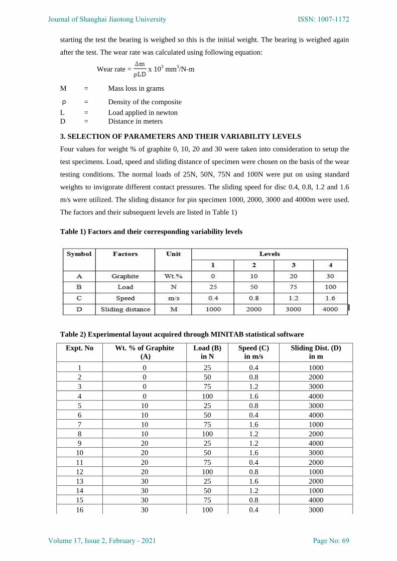
The factors and their subsequent levels are listed in Table 1)
Table 1) Factors and their corresponding variability levels
Table 2) Experimental layout acquired through MINITAB statistical software
Expt. No Wt. % of Graphite
(A)
Load (B)
in N
Speed (C)
in m/s
Sliding Dist. (D)
in m
1 0 25 0.4 1000
2 0 50 0.8 2000
3 0 75 1.2 3000
4 0 100 1.6 4000
5 10 25 0.8 3000
6 10 50 0.4 4000
7 10 75 1.6 1000
8 10 100 1.2 2000
9 20 25 1.2 4000
10 20 50 1.6 3000
11 20 75 0.4 2000
12 20 100 0.8 1000
13 30 25 1.6 2000
14 30 50 1.2 1000
15 30 75 0.8 4000
16 30 100 0.4 3000
Journal of Shanghai Jiaotong University ISSN: 1007-1172
Volume 17, Issue 2, February - 2021 Page No: 69
4. MICRO STRUCTURAL STUDY (X-RAY DIFFRACTION-XRD)
Dispersion of graphite particles in PA66 composites and crystalline phase are found by using
XRD. The relative intensities and their peak positions indicate the crystalline phase of the PA66
and graphite particles and thus, it can be easily known. The intensities of the peak positions allow
enumerating the phases, to find the orientations of the crystals and to establish the atomic
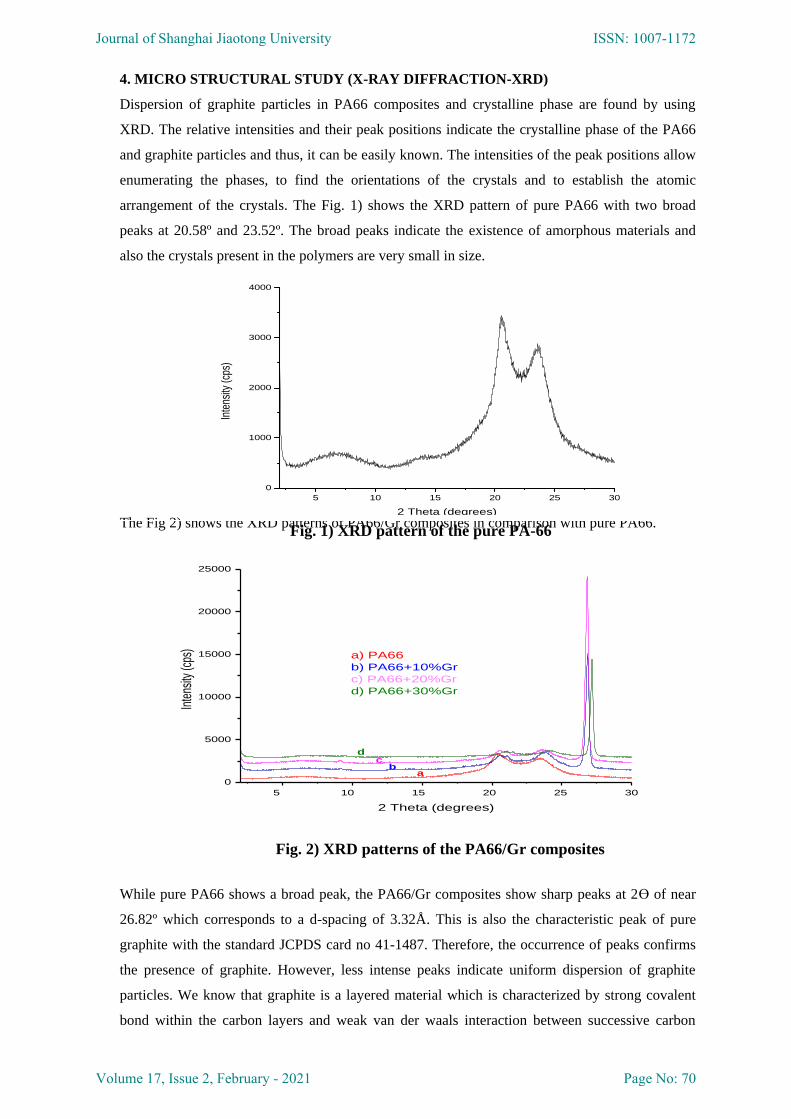
arrangement of the crystals. The Fig. 1) shows the XRD pattern of pure PA66 with two broad
peaks at 20.58º and 23.52º. The broad peaks indicate the existence of amorphous materials and
also the crystals present in the polymers are very small in size.
The Fig 2) shows the XRD patterns of PA66/Gr composites in comparison with pure PA66.
5 10 15 20 25 30
0
5000
10000
15000
20000
25000
Inte
nsity
(cps
)
2 Theta (degrees)
ab
cd
a) PA66
b) PA66+10%Gr
c) PA66+20%Gr
d) PA66+30%Gr
While pure PA66 shows a broad peak, the PA66/Gr composites show sharp peaks at 2Ө of near
26.82º which corresponds to a d-spacing of 3.32Å. This is also the characteristic peak of pure
graphite with the standard JCPDS card no 41-1487. Therefore, the occurrence of peaks confirms
the presence of graphite. However, less intense peaks indicate uniform dispersion of graphite
particles. We know that graphite is a layered material which is characterized by strong covalent
bond within the carbon layers and weak van der waals interaction between successive carbon
5 10 15 20 25 30
0
1000
2000
3000
4000
Inte
nsity
(cps
)
2 Theta (degrees) Fig. 1) XRD pattern of the pure PA-66
Fig. 2) XRD patterns of the PA66/Gr composites
Journal of Shanghai Jiaotong University ISSN: 1007-1172
Volume 17, Issue 2, February - 2021 Page No: 70
layers. Thus variety of atoms and molecules can be intercalated between carbon sheets, resulting
in the formation of intercalated graphite and yielding an increased d-spacing.
5. FRACTURE SURFACE STUDIES
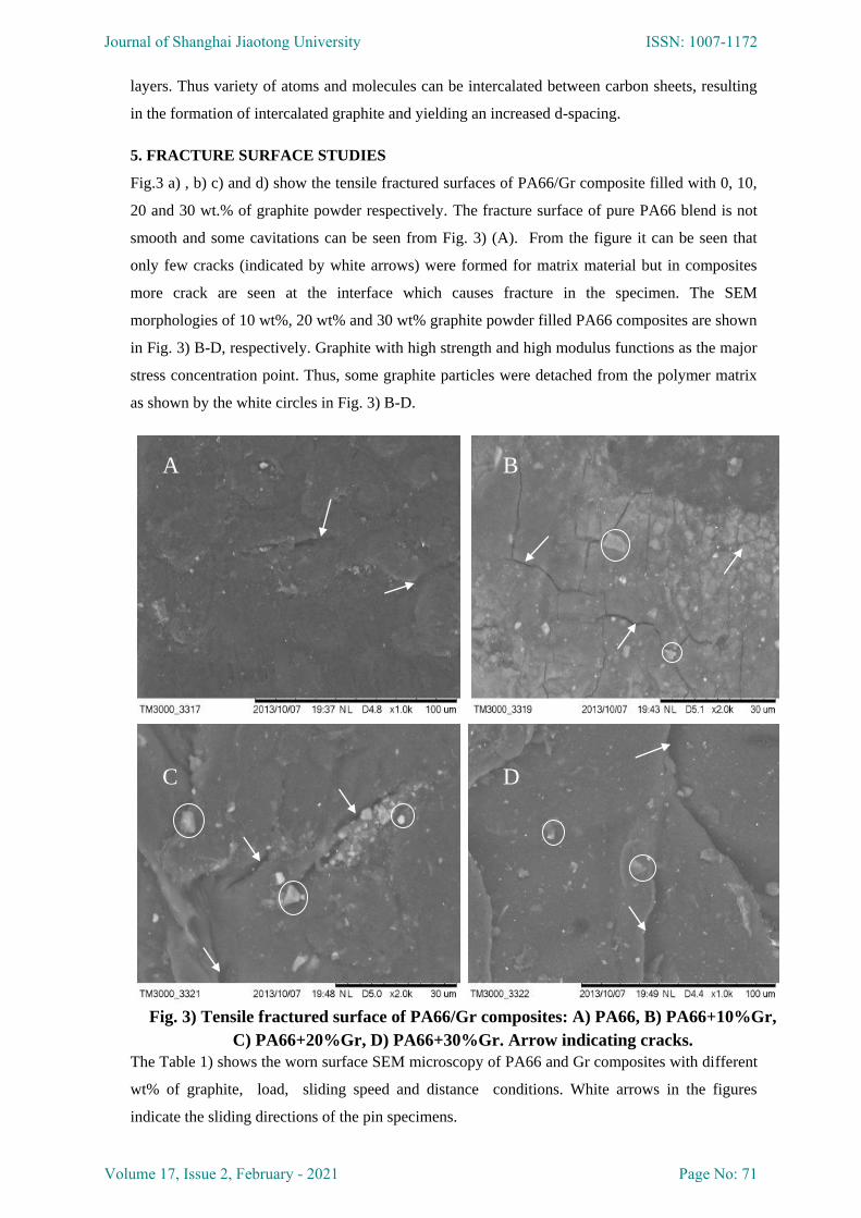
Fig.3 a) , b) c) and d) show the tensile fractured surfaces of PA66/Gr composite filled with 0, 10,
20 and 30 wt.% of graphite powder respectively. The fracture surface of pure PA66 blend is not
smooth and some cavitations can be seen from Fig. 3) (A). From the figure it can be seen that
only few cracks (indicated by white arrows) were formed for matrix material but in composites
more crack are seen at the interface which causes fracture in the specimen. The SEM
morphologies of 10 wt%, 20 wt% and 30 wt% graphite powder filled PA66 composites are shown
in Fig. 3) B-D, respectively. Graphite with high strength and high modulus functions as the major
stress concentration point. Thus, some graphite particles were detached from the polymer matrix
as shown by the white circles in Fig. 3) B-D.
6. WORN-OUT SURFACE STUDIES
The Table 1) shows the worn surface SEM microscopy of PA66 and Gr composites with different
wt% of graphite, load, sliding speed and distance conditions. White arrows in the figures
indicate the sliding directions of the pin specimens.
A B
C D
Fig. 3) Tensile fractured surface of PA66/Gr composites: A) PA66, B) PA66+10%Gr,
C) PA66+20%Gr, D) PA66+30%Gr. Arrow indicating cracks.
Journal of Shanghai Jiaotong University ISSN: 1007-1172
Volume 17, Issue 2, February - 2021 Page No: 71
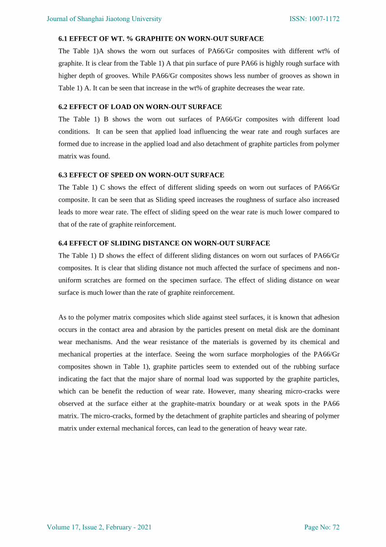
6.1 EFFECT OF WT. % GRAPHITE ON WORN-OUT SURFACE
The Table 1)A shows the worn out surfaces of PA66/Gr composites with different wt% of
graphite. It is clear from the Table 1) A that pin surface of pure PA66 is highly rough surface with
higher depth of grooves. While PA66/Gr composites shows less number of grooves as shown in
Table 1) A. It can be seen that increase in the wt% of graphite decreases the wear rate.
6.2 EFFECT OF LOAD ON WORN-OUT SURFACE
The Table 1) B shows the worn out surfaces of PA66/Gr composites with different load
conditions. It can be seen that applied load influencing the wear rate and rough surfaces are
formed due to increase in the applied load and also detachment of graphite particles from polymer
matrix was found.
6.3 EFFECT OF SPEED ON WORN-OUT SURFACE
The Table 1) C shows the effect of different sliding speeds on worn out surfaces of PA66/Gr
composite. It can be seen that as Sliding speed increases the roughness of surface also increased
leads to more wear rate. The effect of sliding speed on the wear rate is much lower compared to
that of the rate of graphite reinforcement.
6.4 EFFECT OF SLIDING DISTANCE ON WORN-OUT SURFACE
The Table 1) D shows the effect of different sliding distances on worn out surfaces of PA66/Gr
composites. It is clear that sliding distance not much affected the surface of specimens and non-
uniform scratches are formed on the specimen surface. The effect of sliding distance on wear
surface is much lower than the rate of graphite reinforcement.
As to the polymer matrix composites which slide against steel surfaces, it is known that adhesion
occurs in the contact area and abrasion by the particles present on metal disk are the dominant
wear mechanisms. And the wear resistance of the materials is governed by its chemical and
mechanical properties at the interface. Seeing the worn surface morphologies of the PA66/Gr
composites shown in Table 1), graphite particles seem to extended out of the rubbing surface
indicating the fact that the major share of normal load was supported by the graphite particles,
which can be benefit the reduction of wear rate. However, many shearing micro-cracks were
observed at the surface either at the graphite-matrix boundary or at weak spots in the PA66
matrix. The micro-cracks, formed by the detachment of graphite particles and shearing of polymer
matrix under external mechanical forces, can lead to the generation of heavy wear rate.
Journal of Shanghai Jiaotong University ISSN: 1007-1172
Volume 17, Issue 2, February - 2021 Page No: 72
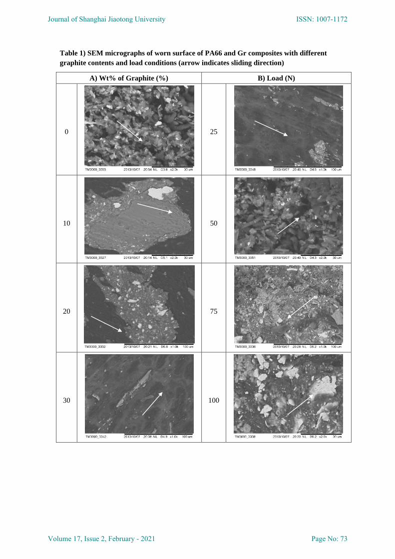
Table 1) SEM micrographs of worn surface of PA66 and Gr composites with different
graphite contents and load conditions (arrow indicates sliding direction)
A) Wt% of Graphite (%) B) Load (N)
0
25
10
50
20
75
30
100
Journal of Shanghai Jiaotong University ISSN: 1007-1172
Volume 17, Issue 2, February - 2021 Page No: 73
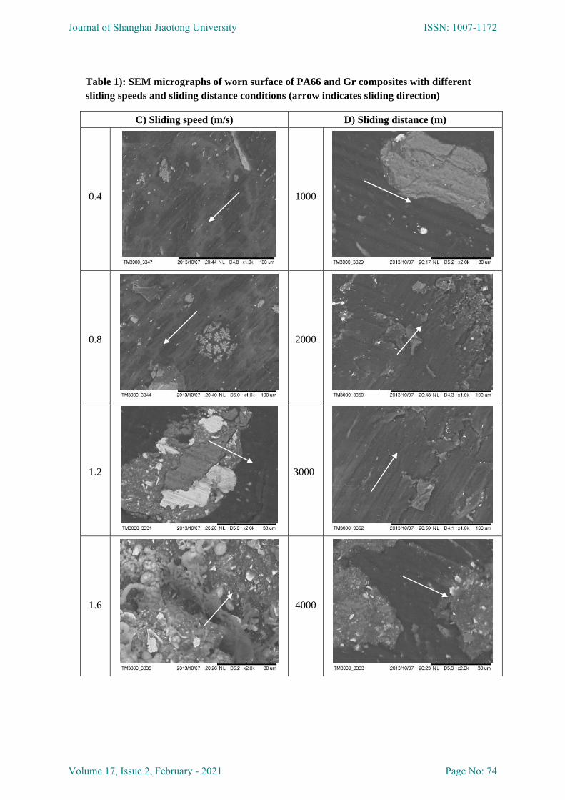
Table 1): SEM micrographs of worn surface of PA66 and Gr composites with different
sliding speeds and sliding distance conditions (arrow indicates sliding direction)
C) Sliding speed (m/s) D) Sliding distance (m)
0.4
1000
0.8
2000
1.2
3000
1.6
4000
Journal of Shanghai Jiaotong University ISSN: 1007-1172
Volume 17, Issue 2, February - 2021 Page No: 74
7. CONCLUSION
Due to the poor interfacial adhesion between graphite particles and polymer matrix, particles can
be detached from the matrix under hard micro-ploughing and micro-cutting attacks by the steel
asperities. Besides, the lack of support and protection of graphite particles produces more weak
spots causing more polymer matrix to be transferred and removed from the composite. From the
reported, it was not easy to find abrasive characteristics thus adhesive wear is the primary
mechanism of the PA66/Gr composites.
During the experiment, graphite particles on the pin transferred to the disc surface were observed
and this film protects the rubbing of surfaces and has lubricant behavior. This process leads to
much lower friction temperature, which leads to reduction in material loss due to wear.
REFERENCES
[1] Beklet.NE, “Tribological behavior of drawn polypropylene”, Wear; vol. 236, pp 55–61, 1999 [2]
Stuart.BH, “Tribological studies of poly (ether ether ketone) blends”, Tribol Int, vol.31,pp 51-647, 1998.
[3] Tsukruk Vladimir.V, “Nano-composite polymer layers for molecular tribology”, Tribol Lett, vol.10, pp
1–2, 2001.
[4] Hu.X, “Tribological behavior of modified polyacetal against MC nylon without lubrication”, Tribol
Lett, vol.5, pp 7-313, 1998.
[5] Davim.JP, Marques.N, “Evaluation tribological behavior polymeric materials for hip prostheses
application”, Tribol Lett, vol.11, pp 4-91, 2001.
[6] H. Unal, A. Mimaroglu, “Friction and wear performance of polyamide 6 and graphite and wax
polyamide 6 composites under dry sliding conditions”, Wear, vol.289, pp 132–137, 2012.
[7] Surapol Raadnui, Sithipong Mahathanabodee, Ruangdaj Tongsri, “Tribological behaviour of sintered
316L stainlesssteel impregnated with MoS2 plain bearing”, Wear, vol. 265, pp 546–553, 2008.
[8] M. Grujicic, V. Sellappana, S. Kotrikaa, G. Arakerea, Andreas, “Suitability analysis of a polymer–
metal hybrid technology based on high-strength steels and direct polymer-to-metal adhesion”, journal of
materials processing technology, vol. 209, pp 1877–1890, 2009.
[9] Z.Z. Zhang, Q.J. Xue, W.M. Liu, W.C. Shen, “Friction and wear properties of metal powder filled PTFE
composites under oil lubricated conditions”, Wear, vol. 210, pp 151–156, 1997.
[10] Osman asi, “An experimental study on the bearing strength behaviour of Al2O3 particle filled glass
fiber reinforced epoxy composites pinned joints”, Composite Structures, vol. 92, pp 354–363, 2012.
Journal of Shanghai Jiaotong University ISSN: 1007-1172
Volume 17, Issue 2, February - 2021 Page No: 75


![Effect of Graphite and Copper Nano-Particles on …...conducting filler in preparing conducting polymer composites [1-3]. Conventional graphite fillers are usually micro-diameter powders](https://img.pdfslide.us/doc/110x75/5f9d54da149f9f3b3b7c9a24/effect-of-graphite-and-copper-nano-particles-on-conducting-filler-in-preparing.jpg)