Embed Size (px)
Citation preview

Investigation of Discharge Arc Phenomena
in Ablative PPT
IEPC-2015-79/ISTS-2015-b-79
Presented at Joint Conference of 30th International Symposium on Space Technology and Science,34th International Electric Propulsion Conference and 6th Nano-satellite Symposium
Hyogo-Kobe, JapanJuly 4–10, 2015
Tony Schonherr∗, Marcus Stein† and Kimiya Komurasaki‡
The University of Tokyo, Bunkyo, Tokyo, 113-8656, Japan
and
Georg Herdrich§
University of Stuttgart, Stuttgart, Baden-Wurttemberg, 70569, Germany
Pulsed plasma thrusters (PPT) transform electric energy into kinetic energy of an ex-haust medium by means of a pulsed discharge. Due to the short discharge time, the natureof the discharge remained unraveled for long time. This study applies optical methods in-cluding high-speed camera observation and emission spectroscopy to describe the dischargearc in a pulsed plasma thruster in detail. Results include the position and width of thearc as a function of time and voltage as well as a description of the species based on thespectral data. Further, by using an analytical method to derive the temperature by theemission profile, a temperature distribution in the discharge area is derived and discussed.
Nomenclature
A = emission probability
c = ion concentration
E = energy of atomic state
g = degeneracy of atomic state
m = electron mass
n = number density
p = pressure
T = excitation temperature
x = axis parallel to the direction of particle exhaust
z = axis parallel to the direction pointing from anode to cathode
ε = emission
λ = wavelength
ν = line wave frequency
∗Assistant Professor, Department of Aeronautics and Astronautics, [email protected].†Graduate Student, Department of Aeronautics and Astronautics, now with Karlsruhe Institute of Technology, Institute of
Technical Thermodynamics, [email protected].‡Professor, Department of Aeronautics and Astronautics, [email protected].§Head of Plasma Wind Tunnel and Electric Propulsion, Institute of Space Systems, [email protected]
1Joint Conference of 30th ISTS, 34th IEPC and 6th NSAT, Hyogo-Kobe, Japan
July 4–10, 2015

I. Introduction
In a pulsed plasma thruster, electrical energy stored in a capacitive device is discharged between twoelectrodes, thereby ionizing the propellant, and accelerating the resulting particle plasma. However, dif-ferences prevail due to the variations in geometric design (coaxial or parallel electrode design), propellant(solid, liquid, gaseous) and so on.
A major observed difference concerns the passage of discharge current through the medium betweenthe electrodes. Resulting from extensive work on gas-fed PPT (GPPT) at Princeton University1, it wasconcluded that the discharge current is pinched into a current sheet, canted due to the Hall effect, andpropagated at velocities exceeding 10 km/s. When investigating ablative PPT, however, a propagatingcurrent sheet was not observed by high-speed photography2–4, emission spectroscopy5, interferometry5,6
or induction probes2,6,7. Instead, the results indicated that the main discharge current stays close to thepropellant surface in form of a diffuse discharge arc, and that the ionized particles are moved and ejectedas a result of the electromagnetic and the slighter electrothermal forces. In this present work, furtheroptical diagnostic experiments are conducted to provide detailed insight into the phenomena concerning thedischarge arc in ablative PPT. To do so, high-speed camera measurements and optical emission spectroscopyalong the axis of acceleration are conducted with focus on the area close to the propellant ablation surfacerather than the plasma plume.
From modeling research on the ablation itself, it was concluded that the ablation is not an instantaneousevent as assumed in the early days of PPT research8, but a rather continuous process that parallels withthe discharge of electrical power9–13. Indications to support this assumption were found in experiments5,14.However, the question remains how the ablated material (in most cases: C2F4) is further decomposed toeventually form the plasma that is accelerated. It is known from emission spectroscopy of the plume that avariety of species exist2,5,15 and that they appear at different timings throughout the discharge16,17. Thisstudy focuses on the creation and movement of the different species as derivable from the above-mentionedexperiments. As is known that the emission is linked to temperature, a analytical method is used to derivethe profile of excitation temperature from the ablation surface towards the plasma plume. The results areused to discuss the energy transfer between discharge energy and plasma.
II. Experimental
A. Thruster and Vacuum Environment
For this study, the PPT ADD SIMP-LEX is used that operates on solid PTFE as propellant and was usedin previous studies17. It comprises of four 20 μF capacitors with a maximum rated voltage of 1300 V, andcopper electrodes that are 20 mm apart at the propellant location. The electrodes are tapered and divergetowards the their tip18. A breech-fed configuration of the propellant is used to allow for visual access to thephenomena occurring close to the propellant surface.
The thruster is placed in a stainless steel vacuum chamber with 0.5 m in diameter, and 1 m in lengththat is pumped down by a two-stage vacuum pump system to an ultimate pressure of about 5 × 10⁻³ Paprior to experiment.
B. Optical Setups
An Ultra-8 high-speed camera, capable of recording 8 pictures with 520x520 pixels, is used to detect theprocesses close to the propellant surface. Previous studies resulted in a choice of 20-100 ns as exposure time.Additionally, bandpass filters were used to observe certain species in the plasma with an FWHM of 10 nm.That is, the multitude of possible spectral lines does not permit to identify undoubtedly certain species. Thecamera is triggered by a pulse delay generator and synchronized with the ignition circuit of the thruster.
A SOL Instruments MS3504i Czerny-Turner monochromator spectrograph is used together with an iCCDcamera to resolve the emission along the axis of exhaust from the propellant surface to about 10 mm from thesurface. The spectral width of the image is 30 nm at 0.12 nm of spectral resolution (limited by spectrograph),which means that to cover the parts of the visible range interesting for this study, the central wavelength isfrequently adjusted. A mercury-vapor lamp as well as a low-pressure cold cathode xenon lamp are used tocalibrate the wavelength of the resulting two-dimensional images in the (x,λ)-plane whereas the x-positionis calibrated by detecting a probe light laser.
2Joint Conference of 30th ISTS, 34th IEPC and 6th NSAT, Hyogo-Kobe, Japan
July 4–10, 2015

III. Temperature Estimation
To derive a temperature profile from the emission spectra, a method proposed by Larenz19 is used. Thismethod considers that emission from a certain spectral line will be increasing as the excitation temperatureincreases, yet the density of the species will decrease with higher temperature as further ionization andexcitation occurs. That is, every spectral line emission peaks at a characteristic temperature. Local thermalequilibrium and a negligible absorption are assumed in the derivation of equations. The two equations themethod is based on are the line emission equation and the Saha equation:
ε =A
4πhν
gegi
· ni · exp−EekT (1)
c2
1− c2· p =
(2πm)3/2
h32gjgi
· (kT )5/2 exp−EjkT (2)
Therein, A refers to the emission probability, h to the Planck constant, g to the degeneracy, n to numberdensity, m to the electron mass, E to the energy, k to the Boltzmann constant, p to the pressure, and T tothe excitation temperature. The ion concentration c is defined by:
ni =1− c
1 + c
p
kT(3)
The indices i, e and j refer to the ground state, the excited state, and the ionized state respectively.Deriving Equation (1) by kT and combining with Equation (2), Larenz derived a transcendent equation forthe temperature at maximum emission T ∗:
h3
(2πm)3/2· 12
gigj
p
E5/2j
·(
Ej
kT ∗
)5/2
· expEjkT∗ =
(Ej
kT∗ + 52
Ea
kT∗ − 1
)2
− 1 (4)
This means, that for any spectral emission line, there is a pressure-dependent characteristic tempera-ture. Considering a single species in PTFE plasma, many spectral emission lines belong to each species, sodepending on the line, the characteristic temperature will be slightly different. For an exemplary emissionline of single-ionized carbon (657.805 nm), Figure 1 shows the normalized relative emission (Eq. (1) withoutline-specific constants normalized by its maximum value) at p = 1 bar as a function of excitation temperaturewith the effect of the Saha equation on ni.
0
0.2
0.4
0.6
0.8
1
10000 15000 20000 25000 30000 35000 40000
Relative
emissionintensity
ε∗,-
Excitation temperature T , K
Figure 1. Spectral emission of C II (657.805 nm) at 1 bar.
The relative emission peaks at around 22400 K, which means that one could expect a plasma to be atthat temperature if found that emission has its maximum there. This principle can be extended to the otherspecies in PTFE plasma as well, and the relative emissions of some characteristic lines are shown in Figure2. The characteristic wavelengths chosen here are strong lines found in PTFE emission spectra in previousstudies5, but the method works for all lines as long as spectral line info is provided. Note that Larenz
3Joint Conference of 30th ISTS, 34th IEPC and 6th NSAT, Hyogo-Kobe, Japan
July 4–10, 2015

pointed out that the calculation method for ions is slightly different than for atoms, but it was demonstratedthat the resulting characteristic temperature varies insignificantly compared to the inaccuracy caused by themissing knowledge of actual pressure.
0
0.2
0.4
0.6
0.8
1
10000 20000 30000 40000 50000 60000 70000
Relative
emissionintensity
ε∗,-
Excitation temperature T , K
C IIC IIIC IVF II
Figure 2. Relative spectral emission of expected common species in PTFE plasma at 1 bar. Respectivewavelengths are 657.805 nm (C II), 464.742 nm (C III), 580.133 nm (C IV), and 402.473 nm (F II).
It is obvious that higher temperatures are needed for highly-ionized species, reflecting the intuitiveexpectation. Maximum emission of single-ionized fluorine is between single-ionized and double-ionized carbonas one would expect looking at the ionization potentials.
To investigate the influence of the pressure on the characteristic temperature, the values were calculatedfor all the emission lines in the investigated wavelength range for all possible species of PTFE plasma. Theresults are plotted in Figure 3 for a pressure range from 0 to 100 kPa. In previous research5, a maximumpressure of about 30 kPa were derived in the plasma plume downstream of the discharge region. As thispressure is varying with time and space, it can only be assumed in this study that the pressure lies with theabove-mentioned range. However, as the results show, the resulting characteristic temperature varies butlittle for a pressure beyond 10 kPa especially for the lower ionization levels. The influence of the pressureuncertainty will, hence, have less impact on the results of the temperature distribution evaluation than theinaccuracies in the emission spectroscopy.
The derived temperature results are used in the next chapter to derive the temperature distribution bycombining them with the spectral emission maxima found by spectroscopy.
IV. Results and Discussion
A. Discharge phenomena
Ignition of the main discharge is triggered by the flashover discharge of a semiconductor igniter implementedin the nominal cathode. After discharge of the igniter, a delay of several microseconds precedes the maindischarge, probably a result of the time it needs for the electrons to reach the nominal anode and formthe discharge arc column. As a result of this delay, imaging of the very beginning of the main discharge isenabled. Exemplary VIS images of the supposed discharge arc are shown in Figure 4 in correlation with thevoltage plot of main discharge, and igniter discharge.
During the initiation of the main discharge, emission of an arc column can be detected. The upperpart of the arc is bent towards the igniter indicating an initial attachment of the arc between the anodeand the positive igniter electrode. The image also indicates the presence of material capable of emittinglight, either from the PTFE block or the electrodes. As the discharge proceeds, the cathode side of the arcrecedes towards the propellant, and emission intensity grows with the increasing current in the arc. The arcremains at its position and in its shape during several microsecond into the discharge. As voltage and currentdecrease, the peak emission moves further downstream, eventually becoming diffuse indicating a disruptionof the arc.
4Joint Conference of 30th ISTS, 34th IEPC and 6th NSAT, Hyogo-Kobe, Japan
July 4–10, 2015

Figure 3. Pressure dependence of characteristic temperatures of spectral emission lines for various speciesfound in PTFE plasma.
Figure 4. Exemplary images of the emission intensity in the visible range recorded by high-speed camera, andtheir respective discharge properties.
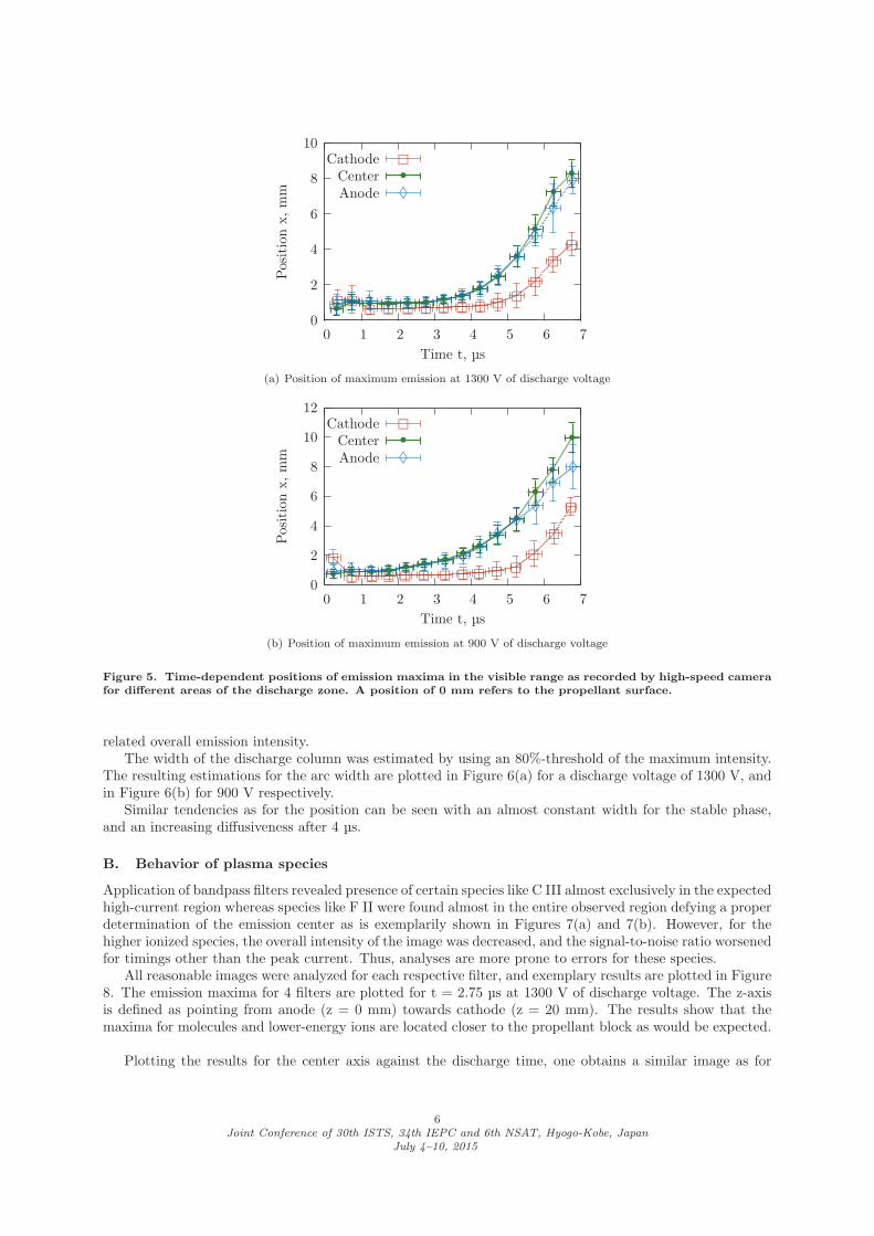
Images were processed and analyzed to derive the position of the discharge column and its width inx-direction (direction of exhaust). The results for the position are plotted in Figures 5(a) and 5(b). Threepositions along the arc were evaluated; one close to each electrode, and one in the middle between them. Anx-position of 0 mm indicates the surface of the solid PTFE propellant block.
Up to about 3 μs into the discharge for 900 V, and up to about 4 μs for 1300 V, the main intensity and,thus, the assumed discharge arc remains stationary. It is only after the decrease of discharge voltage that thearc starts moving away from the propellant surface. In Figure 5(b), it can further be seen how the arc recedesquickly at the cathode side during the first fraction of the discharge. This process is less obvious for higherdischarge voltages. Nevertheless, one clearly observes a stable phase during the high-current part of the firstdischarge, whereas it is only when the discharge current substantially reduces, the arc structure appears tomove out and break apart, although this might also be attributed to the decreasing current density and the
5Joint Conference of 30th ISTS, 34th IEPC and 6th NSAT, Hyogo-Kobe, Japan
July 4–10, 2015
0
2
4
6
8
10
0 1 2 3 4 5 6 7
Positionx,mm
Time t, μs
Cathode
� � � � � � � � � � ��
��
�Center
• • • • • • • • • ••
•
•••
Anode
♦ ♦ ♦ ♦ ♦ ♦ ♦ ♦ ♦♦
♦♦
♦
♦♦
(a) Position of maximum emission at 1300 V of discharge voltage
0
2
4
6
8
10
12
0 1 2 3 4 5 6 7
Positionx,mm
Time t, μs
Cathode
�� � � � � � � � � �
��
�
�Center
• • • • • • • • • ••
••
••Anode
♦ ♦ ♦ ♦ ♦ ♦ ♦ ♦ ♦♦
♦♦
♦♦♦
(b) Position of maximum emission at 900 V of discharge voltage
Figure 5. Time-dependent positions of emission maxima in the visible range as recorded by high-speed camerafor different areas of the discharge zone. A position of 0 mm refers to the propellant surface.
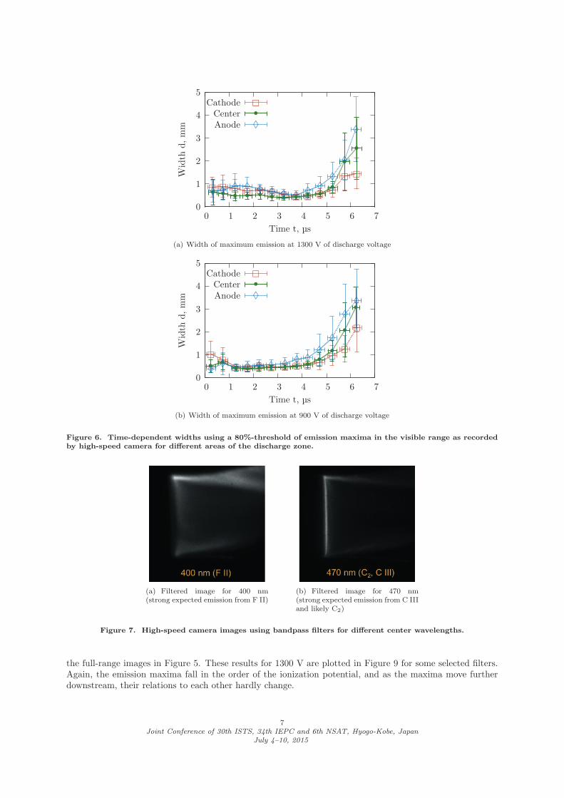
related overall emission intensity.The width of the discharge column was estimated by using an 80%-threshold of the maximum intensity.
The resulting estimations for the arc width are plotted in Figure 6(a) for a discharge voltage of 1300 V, andin Figure 6(b) for 900 V respectively.
Similar tendencies as for the position can be seen with an almost constant width for the stable phase,and an increasing diffusiveness after 4 μs.
B. Behavior of plasma species
Application of bandpass filters revealed presence of certain species like C III almost exclusively in the expectedhigh-current region whereas species like F II were found almost in the entire observed region defying a properdetermination of the emission center as is exemplarily shown in Figures 7(a) and 7(b). However, for thehigher ionized species, the overall intensity of the image was decreased, and the signal-to-noise ratio worsenedfor timings other than the peak current. Thus, analyses are more prone to errors for these species.
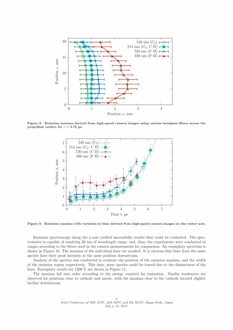
All reasonable images were analyzed for each respective filter, and exemplary results are plotted in Figure8. The emission maxima for 4 filters are plotted for t = 2.75 μs at 1300 V of discharge voltage. The z-axisis defined as pointing from anode (z = 0 mm) towards cathode (z = 20 mm). The results show that themaxima for molecules and lower-energy ions are located closer to the propellant block as would be expected.
Plotting the results for the center axis against the discharge time, one obtains a similar image as for
6Joint Conference of 30th ISTS, 34th IEPC and 6th NSAT, Hyogo-Kobe, Japan
July 4–10, 2015
0
1
2
3
4
5
0 1 2 3 4 5 6 7
Width
d,mm
Time t, μs
Cathode
� � � � � � � � � � �� �
�Center
• • • • • • • • • • •
••
•Anode
♦ ♦ ♦ ♦ ♦ ♦ ♦ ♦ ♦ ♦♦
♦
♦♦
(a) Width of maximum emission at 1300 V of discharge voltage
0
1
2
3
4
5
0 1 2 3 4 5 6 7
Width
d,mm
Time t, μs
Cathode
� �� � � � � � � �
� �
�
�Center
• • • • • • • • • ••
•
•
•Anode
♦ ♦ ♦ ♦ ♦ ♦ ♦ ♦ ♦♦
♦
♦♦♦
(b) Width of maximum emission at 900 V of discharge voltage
Figure 6. Time-dependent widths using a 80%-threshold of emission maxima in the visible range as recordedby high-speed camera for different areas of the discharge zone.
(a) Filtered image for 400 nm(strong expected emission from F II)
(b) Filtered image for 470 nm(strong expected emission from C IIIand likely C2)
Figure 7. High-speed camera images using bandpass filters for different center wavelengths.
the full-range images in Figure 5. These results for 1300 V are plotted in Figure 9 for some selected filters.Again, the emission maxima fall in the order of the ionization potential, and as the maxima move furtherdownstream, their relations to each other hardly change.
7Joint Conference of 30th ISTS, 34th IEPC and 6th NSAT, Hyogo-Kobe, Japan
July 4–10, 2015
0
5
10
15
20
0 1 2 3 4
Positionz,mm
Position x, mm
540 nm (C2)��������������
�514 nm (C2, C II)
��������������
�720 nm (C II)
•••••••••••••
•
•400 nm (F II)
��
��
����
���
��
�
�
Figure 8. Emission maxima derived from high-speed camera images using various bandpass filters across thepropellant surface for t = 2.75 μs.
0
1
2
3
4
5
6
7
0 1 2 3 4 5 6 7
Positionx,mm
Time t, μs
540 nm (C2)
� � � � � � � ��
�
�
�
�514 nm (C2, C II)
�� � � � � � �
��
�
�
��
720 nm (C II)
• • • • • • ••
•
•
•
•400 nm (F II)
�
�� �
� �� � �
�
�
�
Figure 9. Emission maxima with variation in time derived from high-speed camera images on the center axis.
Emission spectroscopy along the x-axis yielded successfully results that could be evaluated. The spec-trometer is capable of resolving 30 nm of wavelength range, and, thus, the experiments were conducted inranges according to the filters used in the camera measurements for comparison. An exemplary spectrum isshown in Figure 10. The maxima of the individual lines are marked. It is obvious that lines from the samespecies have their peak intensity at the same position downstream.
Analysis of the spectra was conducted to evaluate the position of the emission maxima, and the widthof the emission region respectively. This time, more species could be traced due to the distinctness of thelines. Exemplary results for 1300 V are shown in Figure 11.
The maxima fall into order according to the energy required for ionization. Similar tendencies areobserved for positions close to cathode and anode, with the maxima close to the cathode located slightlyfurther downstream.
8Joint Conference of 30th ISTS, 34th IEPC and 6th NSAT, Hyogo-Kobe, Japan
July 4–10, 2015
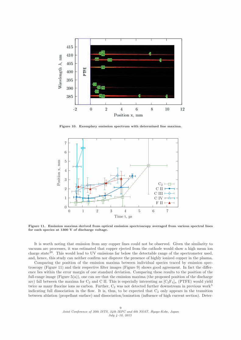
Figure 10. Exemplary emission spectrum with determined line maxima.
0
1
2
3
4
5
6
7
0 1 2 3 4 5 6 7
Positionx,mm
Time t, μs
C2
� � ��
�
�C II
• • ••
•
•C III
♦♦ ♦
♦
♦C IV
�
�
�F II
� ��
�
�
Figure 11. Emission maxima derived from optical emission spectroscopy averaged from various spectral linesfor each species at 1300 V of discharge voltage.
It is worth noting that emission from any copper lines could not be observed. Given the similarity tovacuum arc processes, it was estimated that copper ejected from the cathode would show a high mean ioncharge state20. This would lead to UV emissions far below the detectable range of the spectrometer used,and, hence, this study can neither confirm nor disprove the presence of highly ionized copper in the plasma.
Comparing the position of the emission maxima between individual species traced by emission spec-troscopy (Figure 11) and their respective filter images (Figure 9) shows good agreement. In fact the differ-ence lies within the error margin of one standard deviation. Comparing these results to the position of thefull-range image (Figure 5(a)), one can see that the emission maxima (the proposed position of the dischargearc) fall between the maxima for C2 and C II. This is especially interesting as [C2F4]n (PTFE) would yieldtwice as many fluorine ions as carbon. Further, C2 was not detected further downstream in previous work5
indicating full dissociation in the flow. It is, thus, to be expected that C2 only appears in the transitionbetween ablation (propellant surface) and dissociation/ionization (influence of high current section). Deter-
9Joint Conference of 30th ISTS, 34th IEPC and 6th NSAT, Hyogo-Kobe, Japan
July 4–10, 2015

mination of the arc width by spectroscopy yielded similar results as for the camera measurements. However,due to different sensitivities in the sensors, and overlapping of spectral lines in the wavelength ranges of thebandpass filters, a direct comparison might be challenging.
The accordance of the results between full-range camera images, filtered images, and spectroscopic datais found to be independent of the discharge voltage, thereby supporting the conclusions about the generalnature of the discharge.
C. Temperature Distribution
For the derivation of the temperature distribution, the results of the emission spectroscopy cannot be averagedas the characteristic temperature for each spectral line even of the same species is slightly different. This, ofcourse, increases the susceptibility of the resulting distribution to uncertainties despite the growing numberof data points. As the method proposed in Section III can only be applied to atomic and ionic species, onecannot use the method to the results of the C2 molecule. With numerical modeling of the radiation, it mightbe possible to fit the spectral data to a certain temperature spectrum, but this exceeds the scope of thiswork. To be able to use the data nevertheless, a temperature of 5000 K is assumed. Combining the positionof the emission maxima with the calculated characteristic temperatures, the distribution as shown in Figure12 is derived.
Figure 12. Derived temperature distribution in the 1300 V discharge on the center axis for an assumed pressureof 100 kPa.
Although the inaccuracies of the maxima position and the pressure-dependent temperatures exist, onecan derive valuable information from the distribution. During the initial microsecond, the plasma is heated toits highest temperature within a short distance of 2-3 mm. This is likely due to the high power-to-mass ratioin the discharge creation as not enough material is yet ablated. As the discharge continues the temperatureon average decreases, despite the discharge current increasing. Between 1 to 4 μs, the temperature profilealong x remains mostly constant implying that the variation in discharge current (discharge power) affectsmore strongly the ablation processes rather than the ionization processes. As the current decreases further,the still hot ablation surface yields more material than could be properly heated and ionized, thus, reducingthe overall temperature until the discharge polarity is reversed.
V. Conclusion
High-speed camera measurements and 1D emission spectroscopy were applied successfully for the firsttime to observe the discharge arc in a pulsed plasma thruster, and a temperature distribution profile for thedischarge derived. Major findings include:
1. Three phases of arc behavior could be observed throughout the discharge: formation, maintaining(stable), and eventual disruption of the arc
10Joint Conference of 30th ISTS, 34th IEPC and 6th NSAT, Hyogo-Kobe, Japan
July 4–10, 2015

2. Position and width of arc remain almost constant during the stable phase
3. Maxima of emission intensity occur for each species in order of energy necessary for creation
4. Good accordance between results of camera and spectroscopy (independent of discharge energy)
5. Temperature distribution indicates insufficient ablation during arc initiation, and insufficient ionizationduring disruption
6. Molecular C2 detected close to propellant surface; no electrode material (Cu) observed
Acknowledgments
The authors want to thank Dr. K. Shimamura for assistance in the experimental work.
References
1 Markusic, T. E., Current Sheet Canting in Pulsed Electromagnetic Accelerators, Ph.d. thesis, PrincetonUniversity, Princeton, NJ, USA, June 2002.
2 Koizumi, H., Noji, R., Komurasaki, K., and Arakawa, Y., “Plasma Acceleration Processes in an AblativePulsed Plasma Thruster,” Physics of Plasmas , Vol. 14, No. 3, March 2007, pp. 033506–1–10.
3 Nawaz, A., Bauder, U., Bohrk, H., Herdrich, G., and Auweter-Kurtz, M., “Electrostatic Probe and Cam-era Measurements for Modeling the iMPD SIMP-LEX,” 43rd AIAA/ASME/SAE/ASEE Joint PropulsionConference, July 2007, AIAA-2007-5280.
4 Schonherr, T., Komurasaki, K., Kawashima, R., Arakawa, Y., and Herdrich, G., “Evaluation of DischargeBehavior of the Pulsed Plasma Thruster SIMP-LEX,” 46th AIAA/ASME/SAE/ASEE Joint PropulsionConference, July 2010, AIAA-2010-6530.
5 Schonherr, T., Nees, F., Arakawa, Y., Komurasaki, K., and Herdrich, G., “Characteristics of plasmaproperties in an ablative pulsed plasma thruster,” Physics of Plasmas , Vol. 20, No. 3, March 2013,pp. 033503.
6 Antropov, N. N., Diakonov, G. A., Orlov, M. M., Popov, G. A., Semenikhin, S. A., Tyutin, V. K., andYakovlev, V. N., “Study of Physical Processes and Performance of Ablative Pulsed Plasma Thrusters,”Space Propulsion, May 2010.
7 Lau, M., Manna, S., Herdrich, G., Schonherr, T., and Komurasaki, K., “Investigation of the PlasmaCurrent Density of a Pulsed Plasma Thruster,” Journal of Propulsion and Power , Vol. 30, No. 6, Nov.-Dec. 2014, pp. 1459–1470.
8 Jahn, R. G., Physics of Electric Propulsion, McGraw-Hill Book Company, Inc., New York, NY, USA,1968.
9 Keidar, M., Boyd, I. D., and Beilis, I. I., “On the model of Teflon ablation in an ablation-controlleddischarge,” Journal of Physics D: Applied Physics , Vol. 34, No. 11, June 2001, pp. 1675–1677.
10 Gatsonis, N. A., Juric, D., and Stechmann, D. P., “Numerical Analysis of Teflon Ablation in PulsedPlasma Thrusters,” 43rd AIAA/ASME/SAE/ASEE Joint Propulsion Conference, July 2007, AIAA-2007-5227.
11 Henrikson, E. M. and Mikellides, P. G., “Modeling of Ablation-Fed Pulsed Plasma Thruster OperationUsing a New Approach to the Ablation Process,” 44th AIAA/ASME/SAE/ASEE Joint Propulsion Con-ference, July 2008, AIAA-2008-4645.
12 Kazeev, M. N. and Kozlov, V. F., “Ablation-Fed Discharge Characteristics,” 31st International ElectricPropulsion Conference, Sept. 2009, IEPC-2009-249.
13 Schonherr, T., Zach, W. A., Komurasaki, K., Horner, S., Arakawa, Y., and Herdrich, G., “MechanicalProbe and Modeling Efforts for Evaluation of Plasma Creation and Acceleration in PPT,” 33rd Interna-tional Electric Propulsion Conference, Oct. 2013, IEPC-2013-241.
14 Scharlemann, C. A. and York, T. M., “Mass Flux Measurements in the Plume of a Pulsed PlasmaThruster,” 42nd AIAA/ASME/SAE/ASEE Joint Propulsion Conference, July 2006, AIAA-2006-4856.
15 Beiting, E. J., Qian, J., Russell, R. W., Pollard, J. E., Caven, W., and Corey, R., “Absolute Emission fromthe Mid-infrared to the Extreme Ultraviolet from a Pulsed Plasma Thruster (PPT),” 30th InternationalElectric Propulsion Conference, Sept. 2007, IEPC-2007-268.
11Joint Conference of 30th ISTS, 34th IEPC and 6th NSAT, Hyogo-Kobe, Japan
July 4–10, 2015

16 Thomassen, K. I. and Vondra, R. J., “Exhaust Velocity Studies of a Solid Teflon Pulsed Plasma Thruster,”Journal of Spacecraft and Rockets , Vol. 9, No. 1, Jan. 1972, pp. 61–64.
17 Schonherr, T., Komurasaki, K., and Herdrich, G., “Propellant utilization efficiency in a pulsed plasmathruster,” Journal of Propulsion and Power , Vol. 29, No. 6, Nov.-Dec. 2013, pp. 1478–1487.
18 Schonherr, T., Nawaz, A., Herdrich, G., Roser, H.-P., and Auweter-Kurtz, M., “Influence of ElectrodeShape on Performance of Pulsed Magnetoplasmadynamic Thruster SIMP-LEX,” Journal of Propulsionand Power , Vol. 25, No. 2, March-April 2009, pp. 380–386.
19 Larenz, R. W., “Uber ein Verfahren zur Messung sehr hoher Temperaturen in nahezu durchlassigenBogensaulen,” Zeitschrift fur Physik , Vol. 129, No. 3, May 1951, pp. 327–342.
20 Shaw, P. V., Pulsed Plasma Thrusters for Small Satellites , Ph.d. thesis, University of Surrey, Guildford,UK, June 2011.
12Joint Conference of 30th ISTS, 34th IEPC and 6th NSAT, Hyogo-Kobe, Japan
July 4–10, 2015


![Iepc Epc Profile[1]](https://img.pdfslide.us/doc/110x75/577d35ab1a28ab3a6b91158d/iepc-epc-profile1.jpg)