Embed Size (px)
Citation preview
IEPC-97-165 1008
HIGH POWER ABLATIVE PULSED PLASMA THRUSTER FOR TECHNOLOGY APPLICATIONS
Yu.A. ALEXEEV, M.N. KAZEEV RRC “Kurchatov Institute”, Institute of Nuclear Fusion
Kurchatov sq., 1, Moscow, 123 182
ABSTRACT
The opportunities for high power ablative pulsed plasma thrusters (APPT) developed at lNF, RRC “Kurchatov Institute” within the framework of a program for studying the space plasma thrusters - to be used for technological purposes are considered in the paper. An experimentally based description of the plasma flow produced in high power APPT and its interaction with solid surfaces is presented. Experimental data include measured plasma flow parameters and metallographic study of different steels exposed in pulsed plasma flow. It is shown significant increase in Steel CT-45 hardness (max. - 3.4 times) under the effect of plasma flow and of the number of the plasma shots. For the stainless Steel the plasma processing resulted in extremely strong reduction in the size of grains in the material. Under the plasma flow processing with impurities introduced in an implantation have been obtained with the depth equal 4u and with the concentration - 2-4%. Experiments have shown the high power APPT is a competitive tool for surface processing of different materials.
1. INTRODUCTlON
APPT is a well-known variety of PPT thrusters that was the first one placed to space apparatus Zond-2 more than 30 years ago. Acceleration of the plasma produced as a result of pulsed evaporation of a solid propellant, when a high current discharge is initiated along its surface, is a distinctive feature of APPT. The similar technique automatically provided the matching of a propellant feed with the APPT parameters and allows one to produce a relatively effective plasma acceleration. [ 1-2 ] Multimegawatt coaxial APPT can move close to ideal-like MHD operation. This acceleration
mechanism allows for high efficient power source energy transfer to plasma directed motion energy. APPT calculation models of these devices [3] also promise relatively high efficiency in high power operation mode. High Power APPT(more 10’ W) offer high efficiency at output plasma velocities in the range of 30- 100 km/s. Maximal plasma density reaches 10” cm”. Plasma flow generated is expanded with thermal plasma velocity being order lO”cm/s. Thus there is an opportunity to produce the plasma flow with flow power density that can be varied in a rather wide range (up to 10” W/cm’). Accelerated plasma flow delivered to a target can be used to modify the surface properties of target material while not affecting the underlying bulk properties of the material. Quasi -steady APPT have a number of advantages in their technological implementation: design simplicity (absence of fast responding valves and current commutators), fast ad.justment of flow parameters, conservation of a propellant in a compact form, operation reliability, simplicity of maintenance under industrial conditions. Furthermore, accelerated plasmas offer significant cost advantages over competing advanced laser [4] and chemical technologies by virtue of their high- energy deposition and broad-area coverage on the target, which provide very high processing rates with concomitant high-manufacturing throughput. Typical ion energies are in the range up to 3 keV with flow energy from 0.1 to 100 J/cm2 delivered to the target in a few microseconds. A thin skin of energy from the plasma is deposited on the surface of the target and is transported into the bulk of the material through thermal conduction. The heat pulse delivered to a target by accelerated plasmas can be used to modify the chemistry, crystal morphology, topography, or density of the thin surface layer of a target material while not affecting the underlying bulk properties of the material. Furthermore, accelerated plasmas offer significant cost advantages over competing advanced etching
@Copyright 1997 by the Electric Rocket Propulsion Society. All Rights Reserved.
IEPC-97-165 1009
technologies by virtue of their high-energy deposition and broad-area coverage on the target, which provide very high etch rates with concomitant high- manufacturing throughput. However, full commercialization of accelerated plasma technology requires the means to control the distribution of directed energy on a target located downstream of the accelerator. Another problem is production of plasma flows with different materials. In this paper we present mainly the study of plasma flow interaction with different samples and the results of metallographic measurements of surface modification produced.
2. EXPERIMENTAL FACILITY
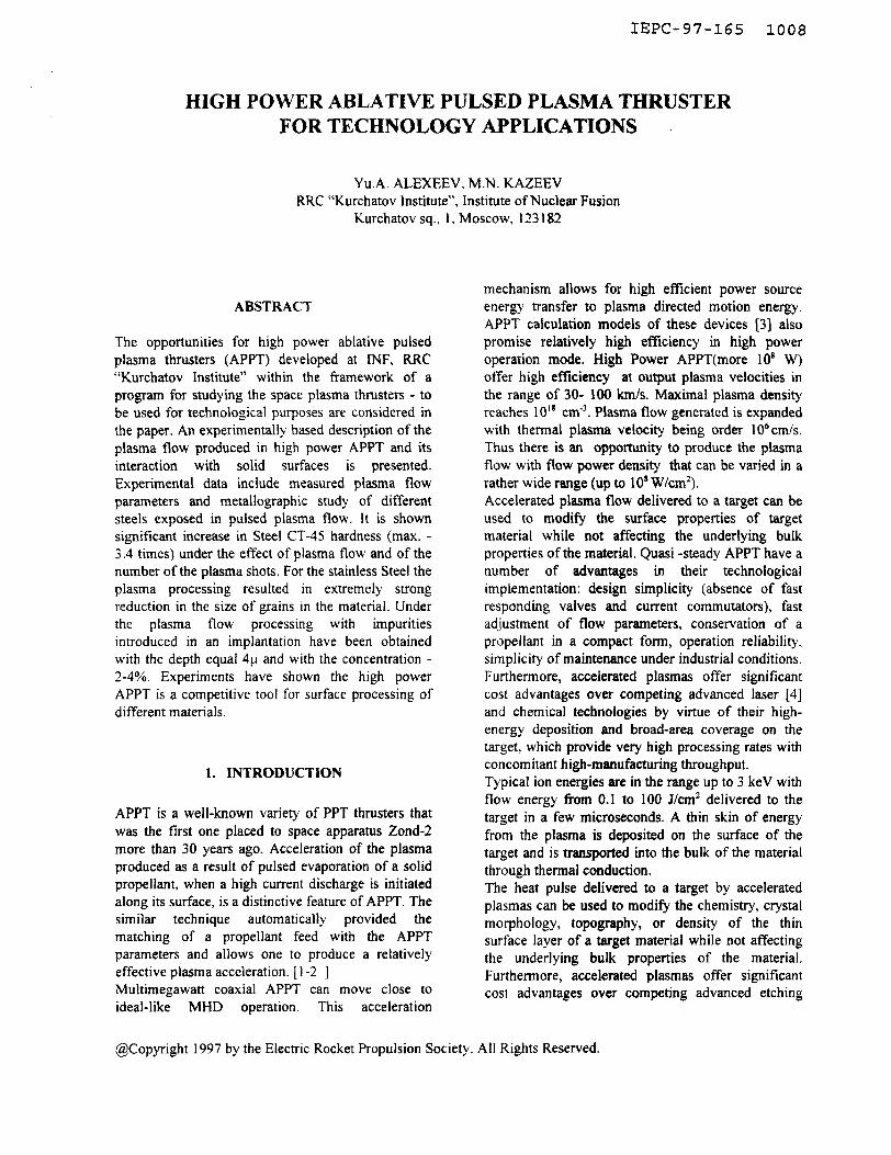
A description of the experimental facility and diagnostics is provided in [5]. The most relevant details are repeated here for the convenience of the reader. The quasisteady APPT is housed in a rectangular stainless steel tank of volume near 1.2 m3. Prior to thruster ignition, the tank is pumped down to approximately 3~10~~ Torr by an oil diffusion pump and mechanical pump. The evacuation velocity is equal 5000 I/s under the pressure 1 O4 Torr. Power is supplied to the thruster by 16 low inductive banks, KMK 20-7-type with the total capacitance about 115 uF. The self inductance of one capacitor is 35 nHe, maximal discharge current, 100 kA. The capacitor bank is connected with the feeder through the low inductive cable bridge composed of 48 high current coaxial cables. The estimated cable bridge inductance is 3 10e9 He. The inductance of vacuum feeder is 10.’ He. The feeder isolation made of acrylic plastic. The thruster (Fig. 1) consists of a cylindrical copper anode and a tungsten cathode. The anode has an outer diameter of 12 cm, an inner diameter of 10 cm and a thickness of 1 cm. The propellant supplied is Teflon. The main high current discharge in accelerating coaxial channel is triggering by a low power spark gap breakdown plasma moving through the holes in the inner electrode to the outer electrode. The maximal charging voltage at plasma source in the absence of commutation devices is determined by the surface breakdown voltage of the working insulator. For the Teflon used in the device under consideration the breakdown voltage is equal 22 kV/cm. Such materials as teflon, porcelain, acrylic plastic, calomel, BNC etc. may be used as operating insulators. High voltage tests of the plasma source were performed at the capacitor bank voltage equal up to 15 kV.
Vacuum Feeder
??== Outer - =4 Electrode
Fig. I. High power APPT design.
3. PLASMA FLOW PARAMETERS
Plasma flows having relatively high range of parameters can be generated in APPT under consideration. The operation mode having high reliability have been chosen for technology demonstration. Main plasma shot characteristics are given in Table 1.
Table 1. APPT CHARACTERISTICS
3.1 IMPURITY INTRODUCING
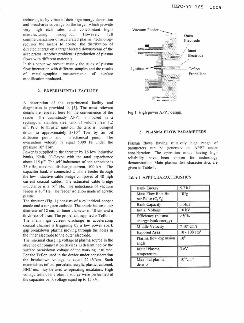
APPT produces CF, plasma flow. Real technologies ask for a variety of materials for implantation, etching. etc. For this reason it is necessary to organize plasma flow that contain different materials. In our experiments impurity addition was produced under the interaction of initial plasma flow with pellets cloud. Successful results were obtained with impurity’ mass in plasma flow cross section being order or smaller of plasma flow mass per shot and with pellet size order of 10” cm. The scheme of impurity introducing into plasma flow is shown in Fig.2. Initial plasma flow parameters in the pellets cloud boundary were: l plasma density -10’6 -10” cm-3
l velocity of plasma -10’ cm/c l plasma flow cross section ~50 cm’. At higher density of pellet cloud initial plasma flow do not penetrate to pellets cloud volume. The distance between pellets cloud and sample varied in a range 150 - 200 mm. Pellets cloud consisted of Zr, B or W pellets. Main experiments were produced with Zr impurities.
Pellets Cloud
Fig.2. Impurity introducing technique flow.
into plasma
4. SOME RESULTS OF THE PLASMA FLOW
INTERACTION WITH SAMPLES
4.1 STEEL 45 (HARDENING)
A change in the steel microhardness under an effect of one or a number of pulses (1, 5, 15 pulses) has been studied. The distance from the plasma source to the sample is 200-250 mm, samples plane was perpendicular to initial flow axis. The samples under
IEPC-97-165 1010
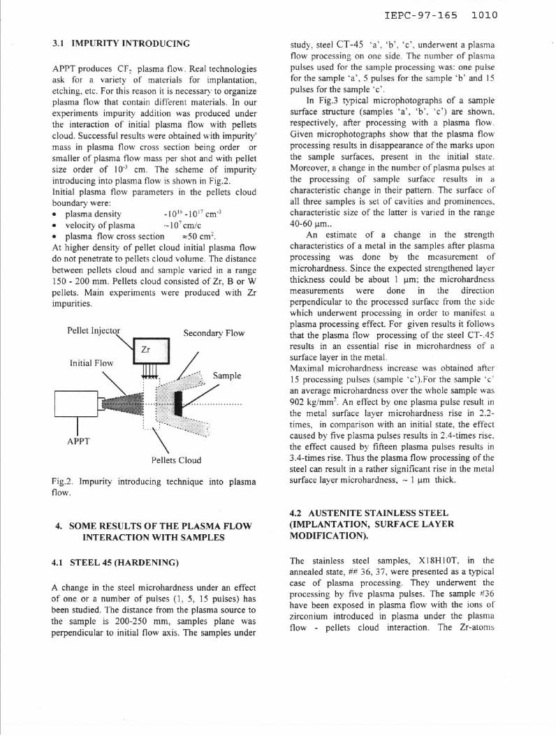
study, steel CT-45 ‘a’. ‘b’, ‘c’, underwent a plasma flow processing on one side. The number of plasma pulses used for the sample processing was: one pulse for the sample ‘a’, 5 pulses for the sample ‘b’ and 15 pulses for the sample ‘c’.
In Fig.3 typical microphotographs of a sample surface structure (samples ‘a’. ‘b’, ‘c’) are shown. respectively, after processing with a plasma flow. Given microphotographs show that the plasma flow processing results in disappearance of the marks upon
the sample surfaces, present in the initial state. Moreover, a change in the number of plasma pulses at the processing of sample surface results in a characteristic change in their pattern. The surface of all three samples is set of cavities and prominences. characteristic size of the latter is varied in the range 40-60 urn..
An estimate of a change in the strength characteristics of a metal in the samples after plasma processing was done by the measurement of microhardness. Since the expected strengthened layer thickness could be about 1 pm: the microhardness measurements were done in the direction perpendicular to the processed surface from the side which underwent processing in order to manifest a plasma processing effect. For given results it follows that the plasma flow processing of the steel CT-.45 results in an essential rise in microhardness of a surface layer in the metal. Maximal microhardness increase was obtained after 15 processing pulses (sample ‘c’).For the sample ‘c’ an average microhardness over the whole sample was 902 kg/mm2. An effect by one plasma pulse result in the metal surface layer microhardness rise in 2.2- times, in comparison with an initial state, the effect caused by five plasma pulses results in 2.4-times rise. the effect caused by fifteen plasma pulses results in 3.4-times rise. Thus the plasma flow processing of the steel can result in a rather significant rise in the metal surface layer microhardness, - 1 pm thick.
4.2 AUSTENITE STAINLESS STEEL (IMPLANTATION, SURFACE LAYER MODIFICATION).
The stainless steel samples, Xl SHIOT, in the annealed state, ## 36, 37, were presented as a typical case of plasma processing. They underwent the processing by five plasma pulses. The sample ii36 have been exposed in plasma flow with the ions of zirconium introduced in plasma under the plasma flow - pellets cloud interaction. The Zr-atoms
I IEPC-97-165 1011
impurity was absent during the processing of the sample =37. other conditions for processing were identical. Initial plasma flow consists of Teflon plasma (CzF4). Impulse parameters are given in section. 3.
I shot
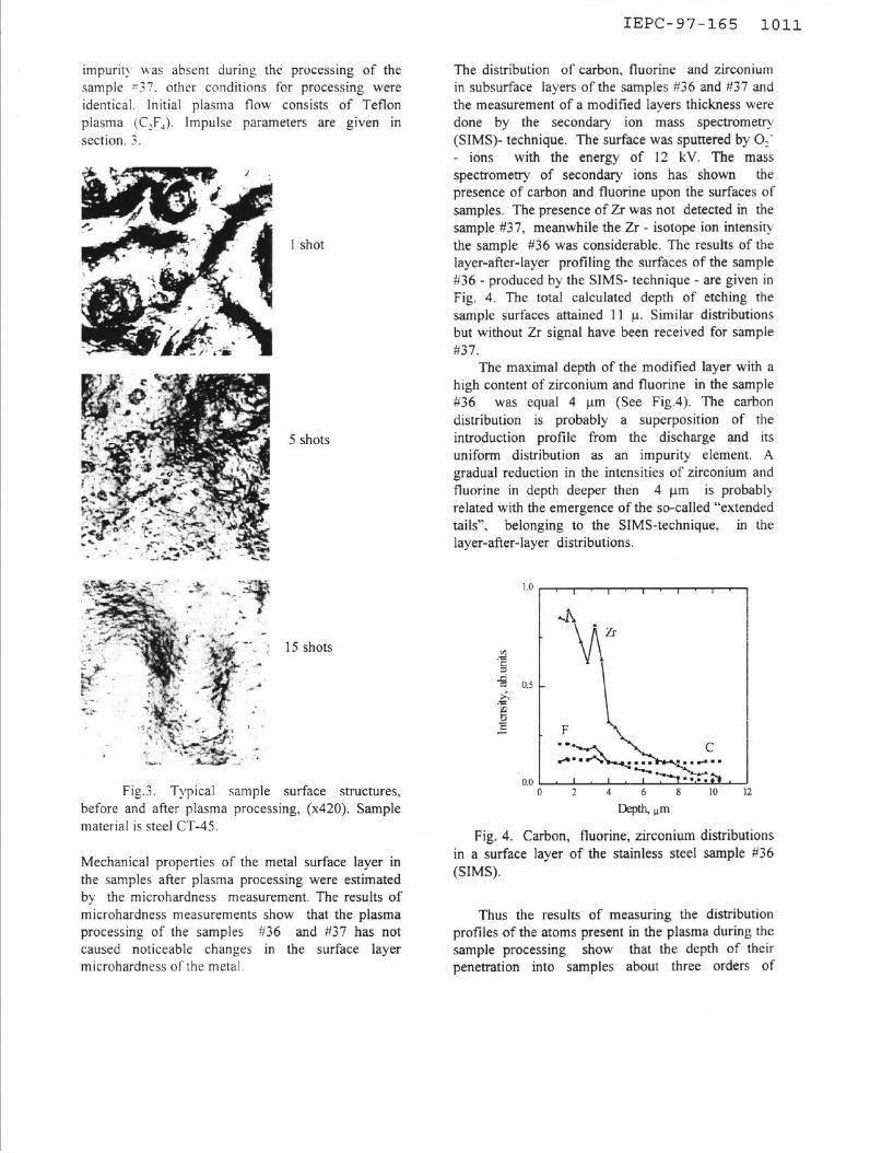
The distribution of carbon, fluorine and zirconium in subsurface layers of the samples #36 and #37 and the measurement of a modified layers thickness were done by the secondary ion mass spectrometry (SIMS)--technique. The surface was sputtered by Oif - ions with the energy of 12 kV. The mass spectrometry of secondary ions has shown the presence of carbon and fluorine upon the surfaces of samples. The presence of Zr was not detected in the sample #37, meanwhile the Zr - isotope ion intensity the sample #36 was considerable. The results of the layer-after-layer profiling the surfaces of the sample #36 - produced by the SIMS- technique - are given in
Fig. 4. The total calculated depth of etching the sample surfaces attained 11 p. Similar distributions but without Zr signal have been received for sample #37.
5 shots
The maximal depth of the modified layer with a high content of zirconium and fluorine in the sample #36 was equal 4 urn (See Fig.4). The carbon distribution is probably a superposition of the introduction profile from the discharge and its uniform distribution as an impurity element. A gradual reduction in the intensities of zirconium and fluorine in depth deeper then 4 urn is probably related with the emergence of the so-called “extended tails”, belonging to the SIMS-technique, in the
15 shots
layer-after-layer distributions.
Fig.3. Typical sample surface structures, before and after plasma processing, (x420). Sample material is steel CT-45.
Fig. 4. Carbon, fluorine, zirconium distributions in a surface layer of the stainless steel sample #36 (SIMS).
Thus the results of measuring the distribution profiles of the atoms present in the plasma during the sample processing show that the depth of their penetration into samples about three orders of
Mechanical properties of the metal surface layer in the samples after plasma processing were estimated by the microhardness measurement. The results of microhardness measurements show that the plasma processing of the samples #36 and #37 has not caused noticeable changes in the surface layer microhardness of the metal.
IEPC-97-165 1012
magnitude exceed the mean free paths ranges of the respective ions (with the energy of - ‘2 keV) in iron.
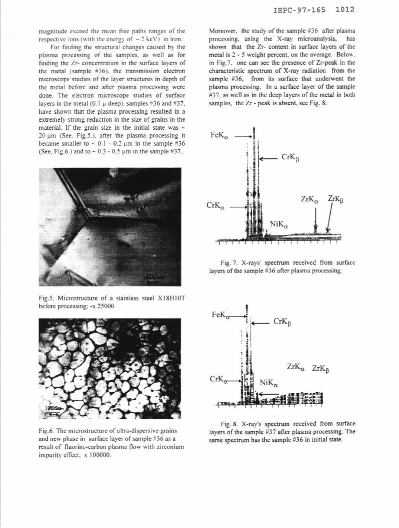
For finding the structural changes caused by the plasma processing of the samples. as well as for finding the Zr- concentration in the surface layers of the metal (sample #36), the transmission electron microscope studies of the layer structures in depth of the metal before and after plasma processing were done. The electron microscope studies of surface layers in the metal (0.1 u deep), samples #36 and #37, have shown that the plasma processing resulted in a
extremely-strong reduction in the size of grains in the material. If the grain size in the initial state was - 20 urn (See. Fig.5.). after the plasma processing it became smaller to - 0.1 - 0.2 urn in the sample #36 (See, Fig.6.) and to - 0.3 - 0.5 urn in the sample #37..
Fig.5. Microstructure of a stainless steel XlSHlOT before processing; -x 25000
Fig.6. The microstructure of ultra-dispersive grains and new phase in surface layer of sample X36 as a result of fluorine-carbon plasma flow with zirconium impurity effect; x 100000.
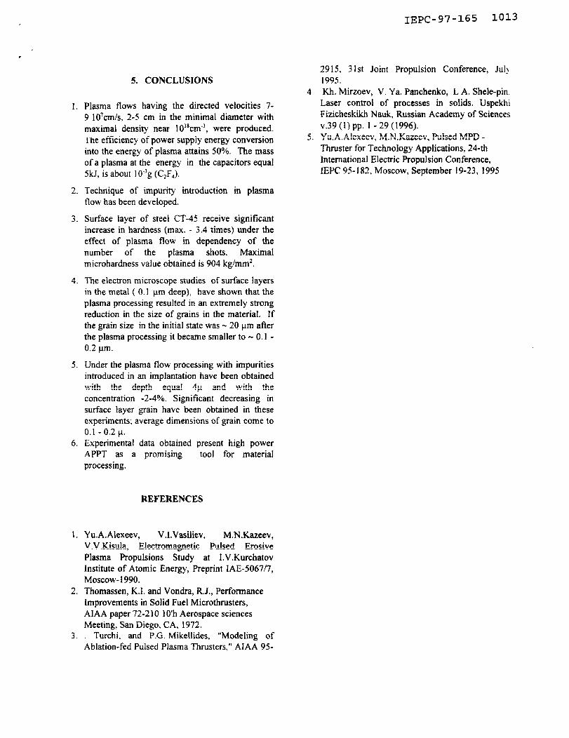
Moreover, the study of the sample #36 after plasma processing, using the X-ray microanalysis, has shown that the Zr- content in surface layers of the metal is 2 - 5 weight percent, on the average. Belou. in Fig.7, one can see the presence of Zr-peak in the characteristic spectrum of X-ray radiation from the sample #36, from its surface that underwent the plasma processing. In a surface layer of the sample #37, as well as in the deep layers of the metal in both samples, the Zr - peak is absent, see Fig. 8.
FeK, II -!!
Fig. 7. X-rays’ spectrum received from surface layers of the sample #36 after plasma processing.
II FeKd i
I; I- CrKp
j f!
b:
Fig. 8. X-ray’s spectrum received from surface layers of the sample #37 after plasma processing. The same spectrum has the sample #36 in initial state.
IEPC-97-165 1013
5. CONCLUSIONS
I. Plasma flows having the directed velocities 7- 9 IO’cmls, 2-5 cm in the minimal diameter with maximal density near 10’8cm~‘, were produced. The efficiency of power supply energy conversion into the energy of plasma attains 50%. The mass of a plasma at the energy in the capacitors equal 5kJ, is about 1 0e3g (C,F,).
2. Technique of impurity introduction in plasma flow has been developed.
3. Surface layer of steel CT-45 receive significant increase in hardness (max. - 3.4 times) under the effect of plasma flow in dependency of the number of the plasma shots. Maximal microhardness value obtained is 904 kg/mm’.
4. The electron microscope studies of surface layers in the metal ( 0.1 urn deep), have shown that the plasma processing resulted in an extremely strong reduction in the size of grains in the material. If the gram size in the initial state was _ 20 urn after the plasma processing it became smaller to - 0.1 - 0.2 urn.
5. Under the plasma flow processing with impurities introduced in an implantation have been obtained with the depth equal 4u and with the concentration -2-4%. Significant decreasing in surface layer grain have been obtained in these experiments: average dimensions of grain come to 0.1 - 0.2 u.
6. Experimental data obtained present high power APPT as a promising tool for material processing.
REFERENCES
1. Yu.A.Alexeev, V.l.Vasiiiev, M.N.Kazeev, V.V.Kisula, Electromagnetic Pulsed Erosive Plasma Propulsions Study at I.V.Kurchatov Institute of Atomic Energy, Preprint IAE-5067/7, Moscow- 1990.
2. Thomassen, K.I. and Vondra, R.J., Performance Improvements in Solid Fuel Microthrusters, AIAA paper 72-2 10 1 O’h Aerospace sciences Meeting, San Diego, CA, 1972.
3. Turchi, and P.G. Mikellides, “Modeling of Ablation-fed Pulsed Plasma Thrusters,” AlAA 95-
2915, 3 1st Joint Propulsion Conference, Jul\ 1995.
4 Kh. Mirzoev, V. Ya. Panchenko, L A. Shele-pin. Laser control of processes in solids. Uspekhi Fizicheskikh Nauk, Russian Academy of Sciences v.39 (1) pp. 1 - 29 (1996).
5. Yu.A.Alexeev, M.N.Kazeev, Pulsed MPD - Thruster for Technology Applications, 24-th International Electric Propulsion Conference, IEPC 95 182, Moscow, September 19-23, 1995