Embed Size (px)
Citation preview
Structural Engineering and Mechanics, Vol. 60, No. 2 (2016) 271-299
DOI: http://dx.doi.org/10.12989/sem.2016.60.2.271 271
Copyright © 2016 Techno-Press, Ltd.
http://www.techno-press.org/?journal=sem&subpage=8 ISSN: 1225-4568 (Print), 1598-6217 (Online)
Investigation of buckling behavior of functionally graded piezoelectric (FGP) rectangular plates under open
and closed circuit conditions
M.A. Ghasemabadiana and M. Kadkhodayan
Department of Mechanical Engineering, Ferdowsi University of Mashhad, Mashhad, Iran
(Received February 7, 2016, Revised July 10, 2016, Accepted July 11, 2016)
Abstract. In this article, based on the higher-order shear deformation plate theory, buckling analysis of a
rectangular plate made of functionally graded piezoelectric materials and its effective parameters are
investigated. Assuming the transverse distribution of electric potential to be a combination of a parabolic and
a linear function of thickness coordinate, the equilibrium equations for the buckling analysis of an FGP
rectangular plate are established. In addition to the Maxwell equation, all boundary conditions including the
conditions on the top and bottom surfaces of the plate for closed and open circuited are satisfied.
Considering double sine solution (Navier solution) for displacement field and electric potential, an analytical
solution is obtained for full simply supported boundary conditions. The accurate buckling load of FGP plate
is presented for both open and closed circuit conditions. It is found that the critical buckling load for open
circuit is more than that of closed circuit in all loading conditions. Furthermore, it is observed that the
influence of dielectric constants on the critical buckling load is more than those of others.
Keywords: buckling; functionally graded piezoelectric; rectangular plate; dielectric constants;
piezoelectric constants; analytical solution
1. Introduction
Functionally graded piezoelectric materials (FGPMs) are a new type of intelligent materials
which have been used in micro-electro-mechanical systems (MEMs) and smart structures as
actuators and sensors (2008b). Because of important applications in medical and aerospace
industry, these materials have attracted attentions in researches. FGPMs have material properties
which vary spatially from a point to another point continuously. The buckling analysis of plates,
shells and beams is one of the most important research fields on isotropic, composite materials,
functionally graded FGMs, piezoelectric materials and FGPMs.
In the case of isotropic and composite materials many researchers have been considered
buckling analysis. For example, Kuo and Yau (2012) derived buckling equations of orthotropic
thin plates using energy approaches. Hosseini-Hashemi et al. (2008a) studied the buckling analysis
Corresponding author, Professor , E-mail: [email protected] aPh.D. Student, E-mail: [email protected]
M.A. Ghasemabadian and M. Kadkhodayan
of in plane loaded isotropic rectangular plates with Levy-type boundary conditions and obtained an analytical closed-form solution. Civalek et al. (2010c) using classical plate theory studied the buckling analysis of rectangular plates subjected to various uniform and non-uniform distributed in-plane compressive loads. The buckling analysis of thin isotropic plates and columns by using differential quadrature (DQ) and harmonic differential quadrature (HDQ) was presented by Civalek (2004a). Using variable refined plate theory, Kim et al. (2009c) investigated the buckling analysis of isotropic and orthotropic simply supported rectangular plates.
For the buckling analysis of functionally graded rectangular plates, based on classical plate theory, Javaheri and Eslami studied the buckling analysis of simply supported plate under mechanical (2002a) and thermal (2002b) loadings. Moreover, Shariat and Eslami (2007) presented a closed form solution for the buckling analysis of simply supported plate based on higher order shear deformation plate theory under mechanical and thermal loadings. The thermal buckling analysis of simply supported plates based on first and third order shear deformation theory was investigated by Lanhe (2004b) and Javaheri and Eslami (2002b), respectively. The critical buckling load for the plate with Levy-type boundary conditions based on classical, first and third order shear deformation theory was presented by Mohammadi et al. (2010e), (2010d) and Bodaghi and Saidi (2010b), respectively. Based on classical plate theory, Amiri Rad and Panahandeh-Shahraki (2014d) investigated the critical buckling load of plates containing a crack. Moreover, Akgöz and Civalek (2014a) investigated the thermo-mechanical size-dependent buckling analysis of functionally graded micro-beams based on the sinusoidal shear deformation beam and modified couple stress theories.
On the other hand, the buckling and post-buckling analysis of piezoelectric plates, have been addressed by many researchers and several works have been conducted to investigate the buckling, post-buckling and thermal buckling behaviors of smart composite plates. For instance, buckling control of laminated composite plates using piezoelectric materials on the basis of the first order shear deformation plate theory was studied by Chandrashekhara and Bathia (1993). Based on the three-dimensional elasticity theory, the dynamic buckling analysis of a plate with surface bonded piezoceramic elements was presented by Batra and Geng (2001a). Varelis and Saravanos (2004c) presented the buckling and post-buckling response of composite laminates and plates with piezo-actuators and sensors due to large displacements and rotations.
Dynamic buckling of laminated plates with piezoelectric sensors and actuators under thermo-electro-mechanical loadings was studied by Shariyat (2009d, 2009e). Based on higher order shear deformation plate theory, he investigated the forced and free vibration and dynamic buckling of rectangular FG plates with piezoelectric sensors and actuators subjected to thermo-electro-mechanical loading conditions. Three-dimensional thermal buckling analysis of simply-supported piezoelectric asymmetric angle-ply laminates with finite layer method studied by Akhras and Li (2010a). Yang (1998) obtained equations for the buckling of a thin piezoelectric plate and showed that the effect of piezoelectricity on the buckling load is of the order of the electro-mechanical coupling factor which is not small when the material has a strong piezoelectric coupling. Based on the higher order shear deformation plate theory, Shen (2005, 2009f) presented the thermal post-buckling analysis of a simply supported laminated plate with piezoelectric actuators subjected to the thermo-electrical and the thermo-electro-mechanical loads. He (2001b) studied the post-buckling analysis of simply supported, symmetric FG plates with fully covered or embedded piezoelectric actuators subjected to the thermo-electro-mechanical loads. Moreover, he presented a fully nonlinear compressive post-buckling and thermal post-buckling analysis for FG hybrid plates with PFRC actuators (2001c). A three-dimensional exact piezoelasticity solution for buckling of
272
Investigation of buckling behavior of functionally graded piezoelectric (FGP) rectangular plates...
simply-supported symmetrically laminated hybrid plates with piezoelectric layers was presented by Kapuria and Achary (2006b). Using three-dimensional state-space formulations, influence of weak interfaces on the buckling of simply supported orthotropic piezoelectric laminates with inter-laminar bonding imperfections was investigated by Kim and Lee (2008b). Moreover, Jadhav and Bajoria (2013b) based on the first order shear deformation plate theory investigated the stability analysis of FGM plate with two piezoelectric layers using finite element method.
The buckling delamination problem of a simply supported sandwich plate-strip with a piezoelectric face and elastic core layers was studied by Akbarov and Yahnioglu (2013a). In order to investigate the effect of stored voltage in actuators, Panahandeh-Shahraki et al. (2014c) presented fully coupled electromechanical buckling analysis of thin to thick active laminated composites. Fereidoon et al. (2014b) introduced an analytical approach for buckling analysis of two layered FGMs that were integrated with surface-bonded piezoelectric actuators subjected to thermo-electro-mechanical loads. Mirzavand and Eslami (2011a) presented a close-form solution for the thermal buckling of functionally graded plates with piezoelectric actuators subjected to thermo-electrical loadings.
Finally, buckling analysis of thick functionally graded piezoelectric rectangular plates was investigated based on the higher-order shear and normal deformable plate theory by Abdollahi et al. (2015). They considered two cases consisting of closed and open–closed circuits as electrical conditions.
Contrary to functionally graded and piezoelectric materials, there are not so many researches on the buckling analysis of functionally graded piezoelectric plates. Although some studies achieved on the buckling of FGPMs referred to buckling analysis of cylindrical shells (2010f) and thick plates (2015), but analysis of the effect of piezoelectric constants on buckling behavior of plates and shells is still an open area and needs more attentions.
According to the all-around literature review, it can be found that there is no work on the investigation of piezoelectric constants effect on the buckling behavior of a rectangular plate made of FGPM. In this study, based on third order shear deformation plate theory, the buckling analysis of simply supported rectangular functionally graded piezoelectric plates for both open and closed circuited electrical conditions are investigated. Assuming the function of electric potential is a combination of parabolic and linear functions of thickness coordinate z, the Maxwell equation and all boundary conditions including the conditions on the top and bottom surfaces of the plate for closed and open circuited are satisfied.
Considering the principle of minimum total potential energy, the equilibrium equations of the plate are derived. By using double series solution, six coupled governing partial differential equations are solved and the accurate critical buckling load is obtained. Verifying the accuracy of the present solution a comparison is performed for a special case of the functionally graded piezoelectric plate without piezoelectric effects. Finally, the effects of plate thickness, piezoelectric constants, piezoelectric index, loading conditions and circuited electrical conditions for some different FGPMs are comprehensively investigated. 2. Geometry and material properties
Consider a flat rectangular plate with the length a, width b, thickness h. The plate is made of FGPM with material properties varying spatially through the thickness direction continuously according to a power law distribution expressed as
273
M.A. Ghasemabadian and M. Kadkhodayan
n
b t b1 z
Θ z Θ Θ Θ2 h
(1)
where n is the material power law index and Θb and Θt denote the material property of the bottom
z=- 2h and top z= 2
h surfaces of the plate, respectively. In this study, Θ demonstrates FGPM
properties such as the elastic (Cij), piezoelectric (eij) and dielectric constants (Ξij). It should be mentioned that FGP is polarized perpendicular to the mid-plane in the direction of the z-axis.
3. Equilibrium and stability equations
Considering the third-order shear deformation plate theory (2010b) and the von-Karman hypothesis for non-linear relation of strain–displacement (2010b), the linear constitutive relations describing the electrical and mechanical interaction of FGPMs in the plane stress state can be written as (2010f)
55
3111 12
3112 11
11 1
5
55 5
2
1
1
0 0 00 00 0 00 0
0 0/ 2 0 0 00 0
0 0 00 0 00 0 00 0 0
xx xx
yy yy x
xy xy y
xz xz z
yz yz
C C
EC
e
eC
C C E
C e EC e
15 11
15 11
31 31 33
0 0 0 0 Ξ 0 0
0 0 0 0 0 Ξ 0
0 0 0 0 0
xx
yyx x
xyy y
xzz z
yz
D e E
D e E
e eD E
(2)
Where [C] is the reduced stiffness matrix at constant electric field, [e] is the reduced matrix of piezoelectric constants, [Ξ] is dielectric constants matrix, {E} is the electric field and {D} is electric displacement field. In order to satisfy the Maxwell equation and the electrical conditions for open and closed circuits, the transverse distribution for electric potential is proposed as
2
2
4Φ , , 1 , , ,
zx y z x y A x y z B x y
h
(3)
Where ϕ is the electric potential on the mid-surface of the FGP layer and A and B are determined through satisfying the electrical boundary conditions on the surfaces of FGP plate. Moreover, based on the linear piezoelectricity, the electric field is the gradient of electric potential as
, , ,Φ , Φ , Φx x y y z zE E E (4)
when both surfaces of the plate are short-circuited, the electrical boundary conditions for a closed circuit piezoelectric layer are represented as
274
Investigation of buckling behavior of functionally graded piezoelectric (FGP) rectangular plates...
Φ , , / 2 0x y h (5)
On the other hand, when the inner surface of the plate is held at zero voltage and the outer surface is in contact with a low permittivity medium such as air or vacuum (open circuit condition), the following surface boundary conditions are assumed
Φ , , / 2 0, , , / 2 0zx y h D x y h (6)
Applying the principle of minimum total potential energy, the equilibrium equations are obtained as
, , 0xx x xy yN N
, , 0xy x yy yN N
, , , , 0xx x xy y xz xx x xy y xM M Q P P R
, , , , 0xy x yy y yz xy x yy y yM M Q P P R
, , , , , , ,
, , ,
2
2 0
xz x yz y xx xx xy xy yy yy x x y y
xx xx xy xy yy yy
Q Q P P P R R
N w N w N w
(7)
where subscripts (,) denotes the differentiation with respect to the Cartesian coordinate and β=3α=4/h2 and Ni, Mi, Pi (i=xx, yy, xy) are the resultant forces, moments and higher-order moments, respectively, and Qi, Ri (i=xz, yz) are the shear and higher-order shear forces, respectively, defined by following relations (2010b)
/2
3
/2
, , 1, , ,h
i i i ih
N M P z z dz
(i=xx, yy, xy)
/2
2
/2
, 1, ,h
i i ih
Q R z dz
(i=xz, yz) (8)
According to the adjacent equilibrium criterion for obtaining the stability equations of buckling, a neighboring state of equilibrium is considered as an increment in the displacement field (1979, 2006a, 2011b). Therefore, the displacement field can be written as
0 1,u u u 0 1 0 1,v v v w w w 0 1x x x 0 1
y y y (9)
where the arrow is read “be replaced by” and superscripts “0” and “1” refer to equilibrium and neighboring states, respectively. Moreover, w is the transverse displacement and ψx and ψy are rotation functions of the middle surface in the x and y directions, respectively, and u and v are the mid-plane displacements of the plate in the x and y directions, respectively.
Substitution of the relations (9) into (8), the expressions for stress resultants related to the equilibrium and neighboring states are obtained as follows
0 0 0 1 1 1, , , , , , ,i i i i i i i i iN M P N M P N M P (i=xx, yy, xy)
0 0 1 1, , , ,i i i i i iQ R Q R Q R (i=xz, yz) (10)
275
M.A. Ghasemabadian and M. Kadkhodayan
where the terms with superscripts 0 related to the equilibrium conditions and those with superscripts 1 are linear parts of the stress resultants increments corresponding to the neighboring state. Substituting relations (10) into Eqs. (7), the terms in the resulting equations with superscript 0 are omitted because of satisfying the equilibrium conditions. Moreover, the non-linear terms with superscript 1 are ignored because of the smallness of the incremental displacement compared to the linear terms. The remaining terms form the stability equations as
1 1, , 0xx x xy yN N
1 1, , 0xy x yy yN N
1 1 1 1 1 1, , , , 0xx x xy y xz xx x xy y xM M Q P P R
1 1 1 1 1 1, , , , 0xy x yy y yz xy x yy y yM M Q P P R
1 1 1 1 1 1 1 0 1, , , , , , , ,
0 1 0 1, ,
2
2 0
xz x yz y xx xx xy xy yy yy x x y y xx xx
xy xy yy yy
Q Q P P P R R N w
N w N w
(11)
where 0 , , ,iN i xx xy yy can be replaced by the pre-buckling forces obtained from equilibrium
conditions. The above equations formed the stability equations of the plate subjected to the in-plane edge loading. Besides mentioned equations, the variables should also satisfy the Maxwell equation which requires that the divergence of the electric flux density vanishes at any point within the media. In order to satisfy this condition, the integration of the electric flux divergence across the thickness of the piezoelectric layers must be zero for any x and y as (2009a)
/2
/2
0h
yx z
h
DD Ddz
x y z
(12)
Substituting relations of displacement and strains into Eqs. (10) and (11) the governing stability equations are obtained as
1 1 1 1 1 11 , , 2 , 3 , 4 , 5 ,
1 16 , 7 , 8 , 0
xxx xyy x xx x yy y xy xx
yy xy x
A w w A A A A u
A u A v A
1 1 1 1 1 11 , , 2 , 3 , 4 , 5 ,
1 16 , 7 , 8 , 0
xxy yyy y yy y xx x xy yy
xx xy y
A w w A A A A v
A v A u A
1 1 1 1 1 1 11 , , 2 , 3 , 4 , 5 , 6 ,
1 1 17 , 8 , 9 , 0
xxx xyy x xx x yy y xy xx yy
xy x x x
B w w B B B B u B u
B v B w B
1 1 1 1 1 1 11 , , 2 , 3 , 4 , 5 , 6 ,
1 1 17 , 8 , 9 , 0
xxy yyy y yy y xx x xy yy xx
xy y y y
B w w B B B B v B v
B u B w B
276
Investigation of buckling behavior of functionally graded piezoelectric (FGP) rectangular plates...
1 1 1 1 1 1 11 , , , 2 , , , ,
1 1 1 1 1 1 1 13 , , , , 4 , , , ,
0 1 0 1 0 15 , , , , ,
2
2 0
xxxx xxyy yyyy x xxx x xyy y yxx y yyy
xxx xyy yxx yyy xx yy x x y y
xx yy xx xx xy xy yy yy
D w w w D
D u u v v D w w
D N w N w N w
1 1 1 1 1 1 11 , , , 2 , , , ,
1 1 1 1 1 1 1 13 , , , , 4 , , 5 , ,
1 16 , , 7 8 , ,
2
0
xxxx xxyy yyyy x xxx x xyy y yxx y yyy
xxx xyy yxx yyy xx yy x x y y
x y xx yy
F w w w F
F u u v v F w w F
F u v F F
(13)
where Ai, Bi, Di and Fi (i=1 to 9) are introduced in the Appendices A and B for open and closed circuit conditions, respectively. Eq. (13) is six highly coupled partial differential equations in terms of neighboring displacement components and mid-plane electrical potential function.
4. Buckling analysis
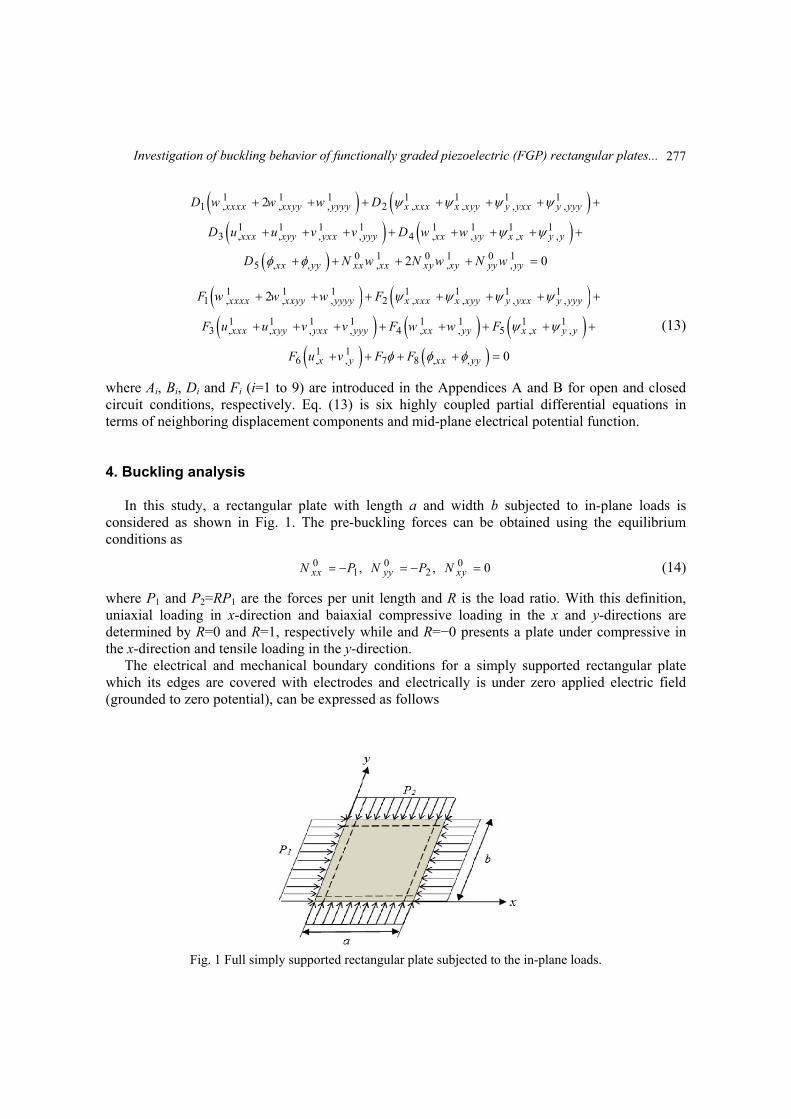
In this study, a rectangular plate with length a and width b subjected to in-plane loads is considered as shown in Fig. 1. The pre-buckling forces can be obtained using the equilibrium conditions as
01 젨,xxN P 0
2 젨,yyN P 0 0xyN (14)
where P1 and P2=RP1 are the forces per unit length and R is the load ratio. With this definition, uniaxial loading in x-direction and baiaxial compressive loading in the x and y-directions are determined by R=0 and R=1, respectively while and R=−0 presents a plate under compressive in the x-direction and tensile loading in the y-direction.
The electrical and mechanical boundary conditions for a simply supported rectangular plate which its edges are covered with electrodes and electrically is under zero applied electric field (grounded to zero potential), can be expressed as follows
Fig. 1 Full simply supported rectangular plate subjected to the in-plane loads.
277
M.A. Ghasemabadian and M. Kadkhodayan
1 1 1 1 1 0y xx xxv w M P at 0,x a
1 1 1 1 1 0x yy yyu w M P at 0,y b (15)
The differential Eq. (13) and boundary conditions (15) for simply-supported rectangular FGPM plate may be satisfied by double trigonometric expansions of the following forms
1 1
, cos sinq p
u x y U x y
1 1
, sin cosq p
v x y V x y
1 1
, cos sinxxq p
x y x y
1 1
, sin cosyyq p
x y x y
1 1
, sin sinq p
w x y W x y
1 1
, sin sinq p
x y x y
(16)
Where μ=πq/b and η=πp/a and p and q are the integer number of half-waves in the x and y directions of buckling mode shape, respectively. Substituting Eqs. (16) into (13), provides a set of homogenous algebraic equations in terms of coefficients and pre-buckling load P1 which may be condensed in the following form
11 12 13 14 15 16
21 22 23 24 25 26
31 32 33 34 35 36
41 42 43 44 45 46
51 52 53 54 55 56
61 62 63 64 65 66
0
0
0
0
0
0
x
y
k k k k k k
k k k k k k
k k k k k k
k k k k k k
k k k k k k
k k k k k k
U
V
W
(17)
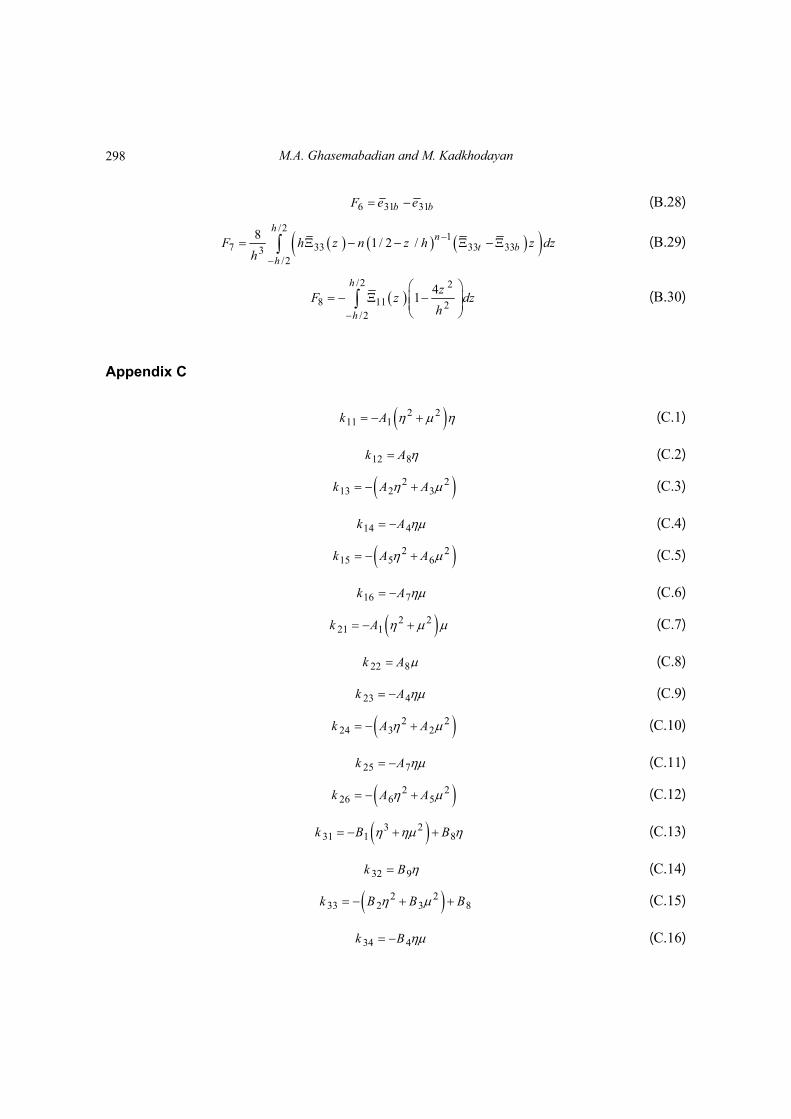
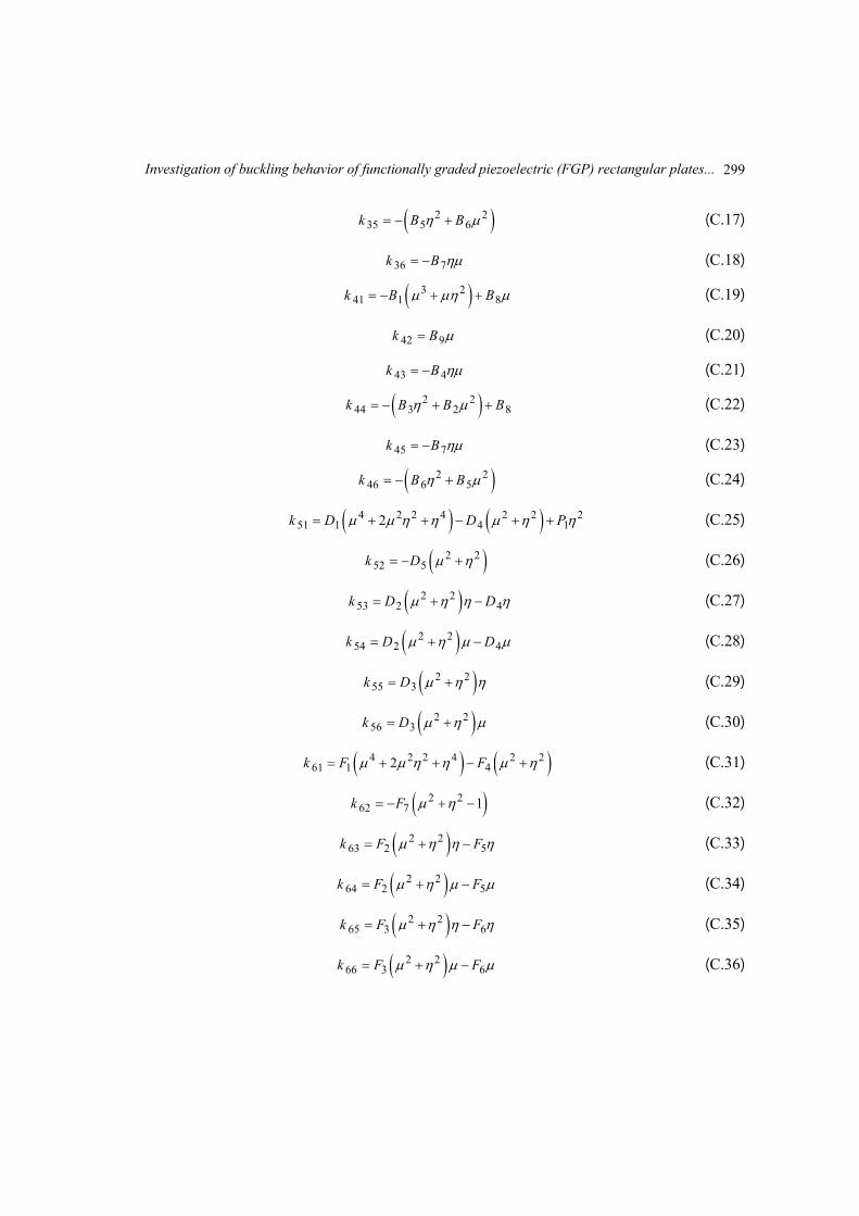
Where kij (i,j=1 to 6) are introduced in the Appendix C. Non-trivial solution of the system may be obtained when the determinant of the sixth order coefficient matrix is set equal to zero for the buckling loads which results the characteristic equation. To evaluate the buckling load of FGP plate the characteristic equation has to be solved. The critical buckling load is the minimum value among all these P1 and denoted by Pcr.
5. Verification of results
278
Investigation of buckling behavior of functionally graded piezoelectric (FGP) rectangular plates...
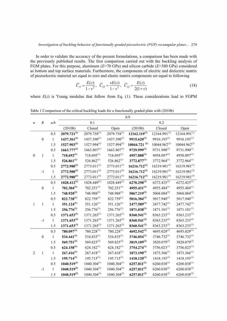
In order to validate the accuracy of the present formulations, a comparison has been made with the previously published results. The first comparison carried out with the buckling analysis of FGM plates. For this purpose, aluminum (E=70 GPa) and silicon carbide (E=380 GPa) considered as bottom and top surface materials. Furthermore, the components of electric and dielectric matrix of piezoelectric material set equal to zero and elastic matrix components set equal to following
)1(2
)( ,
1
)( ,
1
)(22222211 v
zEC
v
zvEC
v
zEC
(18)
where E(z) is Young modulus that follow from Eq. (1). These considerations lead to FGPM Table 1 Comparison of the critical buckling loads for a functionally graded plate with (2010b)
n R a/b
h/b
0.1 0.2
(2010b) Closed Open (2010b) Closed Open
0
0
0.5 2079.721(1) 2079.758(1) 2079.758(1) 12162.119(1) 12164.991(1) 12164.991(1)
1 1437.361(1) 1437.390(1) 1437.390(1) 9915.620(1) 9916.193(1) 9916.193(1)
1.5 1527.903(2) 1527.994(2) 1527.994(2) 10044.721 (2) 10044.962(2) 10044.962(2)
1
0.5 1663.777(1) 1663.807(1) 1663.807(1) 9729.999(1) 9731.990(1) 9731.990(1)
1 718.692(1) 718.695(1) 718.695(1) 4957.888(1) 4958.097(1) 4958.097(1)
1.5 526.861(1) 526.862(1) 526.862(1) 3772.877(1) 3772.964(1) 3772.964(1)
-1
0.5 2772.980(1) 2773.011(1) 2773.011(1) 16216.712(1) 16219.981(1) 16219.981(1)
1 2772.980(2) 2773.011(2) 2773.011(2) 16216.712(2) 16219.981(2) 16219.981(2)
1.5 2772.980(3) 2773.011(3) 2773.011(3) 16216.712(3) 16219.981(3) 16219.981(3)
1
0
0.5 1028.412(1) 1028.449(1) 1028.449(1) 6270.298(1) 6272.425(1) 6272.425(1)
1 702.304(1) 702.251(1) 702.251(1) 4955.431(1) 4955.484(1) 4955.484(1)
1.5 748.920(2) 748.988(2) 748.988(2) 5067.219(2) 5068.084(2) 5068.084(2)
1
0.5 822.738(1) 822.759(1) 822.759(1) 5016.384(1) 5017.940(1) 5017.940(1)
1 351.124(1) 351.126(1) 351.126(1) 2477.589(1) 2477.742(1) 2477.742(1)
1.5 256.776(1) 256.776(1) 256.776(1) 1871.038(1) 1871.101(1) 1871.101(1)
-1
0.5 1371.653(1) 1371.265(1) 1371.265(1) 8360.541(1) 8363.233(1) 8363.233(1)
1 1371.653(2) 1371.265(2) 1371.265(2) 8360.541(2) 8363.233(2) 8363.233(2)
1.5 1371.653(3) 1371.265(3) 1371.265(3) 8360.541(3) 8363.233(3) 8363.233(3)
2
0
0.5 780.097(1) 780.228(1) 780.228(1) 4692.542(1) 4695.029(1) 4695.029(1)
1 534.441(1) 534.835(1) 534.835(1) 3746.054(1) 3746.732(1) 3746.732(1)
1.5 569.751(2) 569.825(2) 569.825(2) 3819.109(2) 3820.079(2) 3820.079(2)
1
0.5 624.158(1) 624.182(1) 624.182(1) 3754.274(1) 3756.023(1) 3756.023(1)
1 267.416(1) 267.418(1) 267.418(1) 1873.190(1) 1873.366(1) 1873.366(1)
1.5 195.714(1) 195.715(1) 195.715(1) 1418.120(1) 1418.193(1) 1418.193(1)
-1
0.5 1040.519(1) 1040.304(1) 1040.304(1) 6257.811(1) 6260.038(1) 6260.038(1)
1 1040.519(2) 1040.304(2) 1040.304(2) 6257.811(2) 6260.038(2) 6260.038(2)
1.5 1040.519(3) 1040.304(3) 1040.304(3) 6257.811(3) 6260.038(3) 6260.038(3)
279
M.A. Ghasemabadian and M. Kadkhodayan
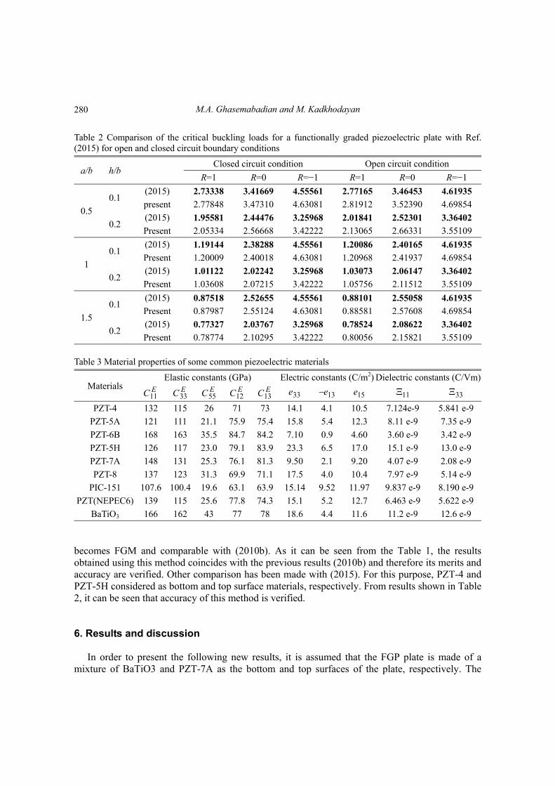
Table 2 Comparison of the critical buckling loads for a functionally graded piezoelectric plate with Ref. (2015) for open and closed circuit boundary conditions
a/b h/b Closed circuit condition Open circuit condition
R=1 R=0 R=−1 R=1 R=0 R=−1
0.5
0.1 (2015) 2.73338 3.41669 4.55561 2.77165 3.46453 4.61935
present 2.77848 3.47310 4.63081 2.81912 3.52390 4.69854
0.2 (2015) 1.95581 2.44476 3.25968 2.01841 2.52301 3.36402
Present 2.05334 2.56668 3.42222 2.13065 2.66331 3.55109
1
0.1 (2015) 1.19144 2.38288 4.55561 1.20086 2.40165 4.61935
Present 1.20009 2.40018 4.63081 1.20968 2.41937 4.69854
0.2 (2015) 1.01122 2.02242 3.25968 1.03073 2.06147 3.36402
Present 1.03608 2.07215 3.42222 1.05756 2.11512 3.55109
1.5
0.1 (2015) 0.87518 2.52655 4.55561 0.88101 2.55058 4.61935
Present 0.87987 2.55124 4.63081 0.88581 2.57608 4.69854
0.2 (2015) 0.77327 2.03767 3.25968 0.78524 2.08622 3.36402
Present 0.78774 2.10295 3.42222 0.80056 2.15821 3.55109
Table 3 Material properties of some common piezoelectric materials
Dielectric constants (C/Vm)Electric constants (C/m2)Elastic constants (GPa) Materials
33 11 15e 13e33e13EC12
EC55EC 33
EC 11EC
5.841 e-97.124e-9 10.54.1 14.173 71 26 115 132 PZT-4
7.35 e-9 8.11 e-9 12.35.4 15.875.475.921.1 111 121 PZT-5A
3.42 e-9 3.60 e-9 4.600.9 7.1084.284.735.5 163 168 PZT-6B
13.0 e-9 15.1 e-9 17.06.5 23.383.979.123.0 117 126 PZT-5H
2.08 e-9 4.07 e-9 9.202.1 9.5081.376.125.3 131 148 PZT-7A
5.14 e-9 7.97 e-9 10.44.0 17.571.169.931.3 123 137 PZT-8
8.190 e-99.837 e-9 11.979.52 15.1463.963.119.6 100.4 107.6 PIC-151
5.622 e-96.463 e-9 12.75.2 15.174.377.825.6 115 139 PZT(NEPEC6)
12.6 e-9 11.2 e-9 11.64.4 18.678 77 43 162 166 BaTiO3
becomes FGM and comparable with (2010b). As it can be seen from the Table 1, the results obtained using this method coincides with the previous results (2010b) and therefore its merits and accuracy are verified. Other comparison has been made with (2015). For this purpose, PZT-4 and PZT-5H considered as bottom and top surface materials, respectively. From results shown in Table 2, it can be seen that accuracy of this method is verified.
6. Results and discussion
In order to present the following new results, it is assumed that the FGP plate is made of a mixture of BaTiO3 and PZT-7A as the bottom and top surfaces of the plate, respectively. The
280
Investigation of buckling behavior of functionally graded piezoelectric (FGP) rectangular plates...
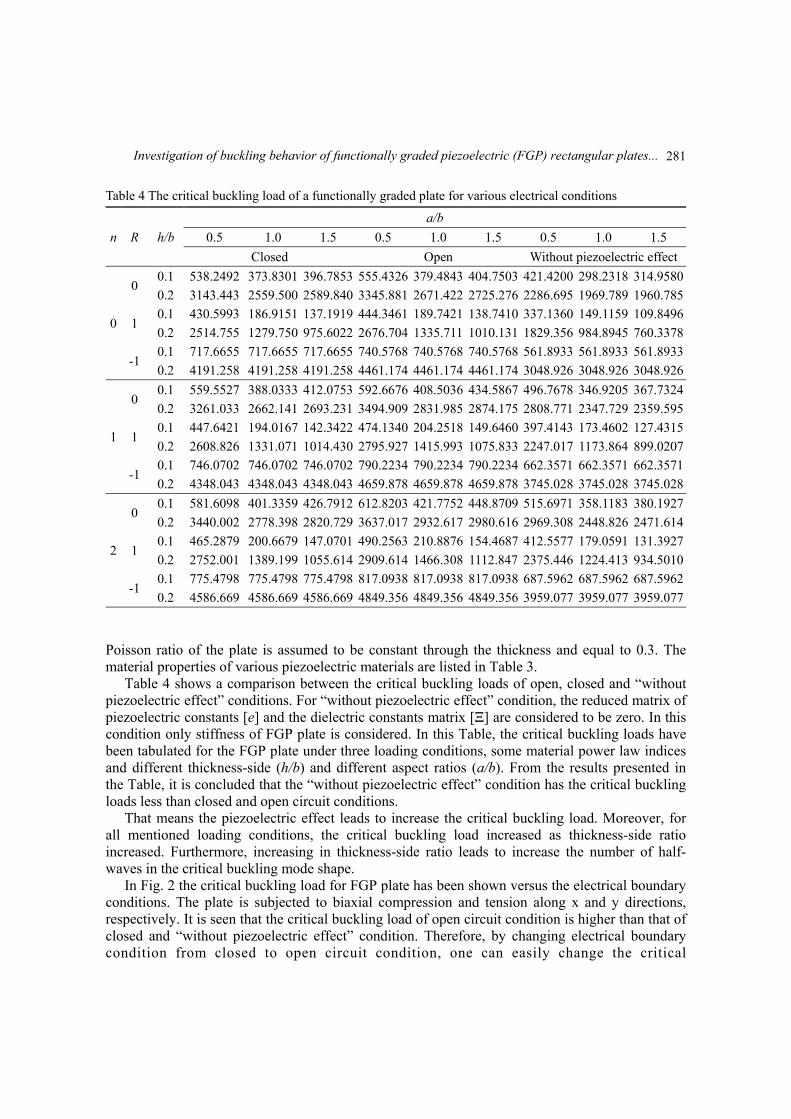
Table 4 The critical buckling load of a functionally graded plate for various electrical conditions
n R h/b
a/b
0.5 1.0 1.5 0.5 1.0 1.5 0.5 1.0 1.5
Closed Open Without piezoelectric effect
0
0 0.1 538.2492 373.8301 396.7853 555.4326 379.4843 404.7503 421.4200 298.2318 314.9580
0.2 3143.443 2559.500 2589.840 3345.881 2671.422 2725.276 2286.695 1969.789 1960.785
1 0.1 430.5993 186.9151 137.1919 444.3461 189.7421 138.7410 337.1360 149.1159 109.8496
0.2 2514.755 1279.750 975.6022 2676.704 1335.711 1010.131 1829.356 984.8945 760.3378
-1 0.1 717.6655 717.6655 717.6655 740.5768 740.5768 740.5768 561.8933 561.8933 561.8933
0.2 4191.258 4191.258 4191.258 4461.174 4461.174 4461.174 3048.926 3048.926 3048.926
1
0 0.1 559.5527 388.0333 412.0753 592.6676 408.5036 434.5867 496.7678 346.9205 367.7324
0.2 3261.033 2662.141 2693.231 3494.909 2831.985 2874.175 2808.771 2347.729 2359.595
1 0.1 447.6421 194.0167 142.3422 474.1340 204.2518 149.6460 397.4143 173.4602 127.4315
0.2 2608.826 1331.071 1014.430 2795.927 1415.993 1075.833 2247.017 1173.864 899.0207
-1 0.1 746.0702 746.0702 746.0702 790.2234 790.2234 790.2234 662.3571 662.3571 662.3571
0.2 4348.043 4348.043 4348.043 4659.878 4659.878 4659.878 3745.028 3745.028 3745.028
2
0 0.1 581.6098 401.3359 426.7912 612.8203 421.7752 448.8709 515.6971 358.1183 380.1927
0.2 3440.002 2778.398 2820.729 3637.017 2932.617 2980.616 2969.308 2448.826 2471.614
1 0.1 465.2879 200.6679 147.0701 490.2563 210.8876 154.4687 412.5577 179.0591 131.3927
0.2 2752.001 1389.199 1055.614 2909.614 1466.308 1112.847 2375.446 1224.413 934.5010
-1 0.1 775.4798 775.4798 775.4798 817.0938 817.0938 817.0938 687.5962 687.5962 687.5962
0.2 4586.669 4586.669 4586.669 4849.356 4849.356 4849.356 3959.077 3959.077 3959.077
Poisson ratio of the plate is assumed to be constant through the thickness and equal to 0.3. The material properties of various piezoelectric materials are listed in Table 3.
Table 4 shows a comparison between the critical buckling loads of open, closed and “without piezoelectric effect” conditions. For “without piezoelectric effect” condition, the reduced matrix of piezoelectric constants [e] and the dielectric constants matrix [Ξ] are considered to be zero. In this condition only stiffness of FGP plate is considered. In this Table, the critical buckling loads have been tabulated for the FGP plate under three loading conditions, some material power law indices and different thickness-side (h/b) and different aspect ratios (a/b). From the results presented in the Table, it is concluded that the “without piezoelectric effect” condition has the critical buckling loads less than closed and open circuit conditions.
That means the piezoelectric effect leads to increase the critical buckling load. Moreover, for all mentioned loading conditions, the critical buckling load increased as thickness-side ratio increased. Furthermore, increasing in thickness-side ratio leads to increase the number of half-waves in the critical buckling mode shape.
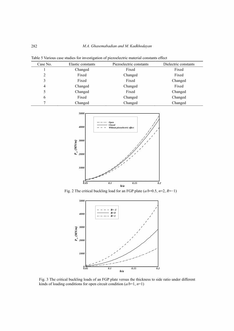
In Fig. 2 the critical buckling load for FGP plate has been shown versus the electrical boundary conditions. The plate is subjected to biaxial compression and tension along x and y directions, respectively. It is seen that the critical buckling load of open circuit condition is higher than that of closed and “without piezoelectric effect” condition. Therefore, by changing electrical boundary condition from closed to open circuit condition, one can easily change the critical
281
M.A. Ghasemabadian and M. Kadkhodayan
Table 5 Various case studies for investigation of piezoelectric material constants effect
Case No. Elastic constants Piezoelectric constants Dielectric constants 1 Changed Fixed Fixed
2 Fixed Changed Fixed
3 Fixed Fixed Changed
4 Changed Changed Fixed
5 Changed Fixed Changed
6 Fixed Changed Changed
7 Changed Changed Changed
h/a
Pcr
(MN
/m)
0.05 0.1 0.15 0.20
1000
2000
3000
4000
5000
OpenClosedWhitout piezoelectric effect
Fig. 2 The critical buckling load for an FGP plate (a/b=0.5, n=2, R=−1)
h/a
Pcr
(MN
/m)
0.05 0.1 0.15 0.20
1000
2000
3000
4000
5000
R= -1R= 0R= 1
Fig. 3 The critical buckling loads of an FGP plate versus the thickness to side ratio under different kinds of loading conditions for open circuit condition (a/b=1, n=1)
282
Investigation of buckling behavior of functionally graded piezoelectric (FGP) rectangular plates...
h/a
Pcr
(MN
/m)
0.05 0.1 0.15 0.20
200
400
600
800
1000
1200
1400
n= 100n= 10n= 2n= 0
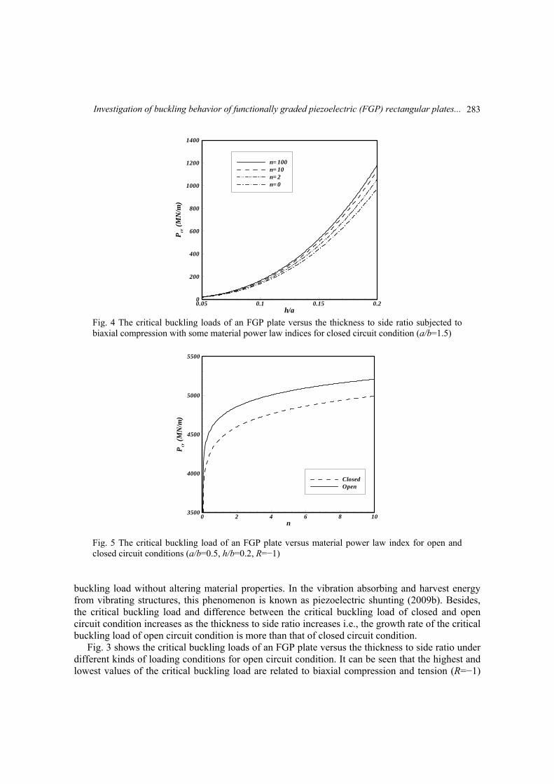
Fig. 4 The critical buckling loads of an FGP plate versus the thickness to side ratio subjected to biaxial compression with some material power law indices for closed circuit condition (a/b=1.5)
n
Pcr
(MN
/m)
0 2 4 6 8 103500
4000
4500
5000
5500
ClosedOpen
Fig. 5 The critical buckling load of an FGP plate versus material power law index for open and closed circuit conditions (a/b=0.5, h/b=0.2, R=−1)
buckling load without altering material properties. In the vibration absorbing and harvest energy from vibrating structures, this phenomenon is known as piezoelectric shunting (2009b). Besides, the critical buckling load and difference between the critical buckling load of closed and open circuit condition increases as the thickness to side ratio increases i.e., the growth rate of the critical buckling load of open circuit condition is more than that of closed circuit condition.
Fig. 3 shows the critical buckling loads of an FGP plate versus the thickness to side ratio under different kinds of loading conditions for open circuit condition. It can be seen that the highest and lowest values of the critical buckling load are related to biaxial compression and tension (R=−1)
283
M.A. Ghasemabadian and M. Kadkhodayan
h
Pcr
0.05 0.1 0.15 0.20
800
1600
2400
3200
BaTiO3
PZT-6BNEPEC6PZT-4PZT-5A
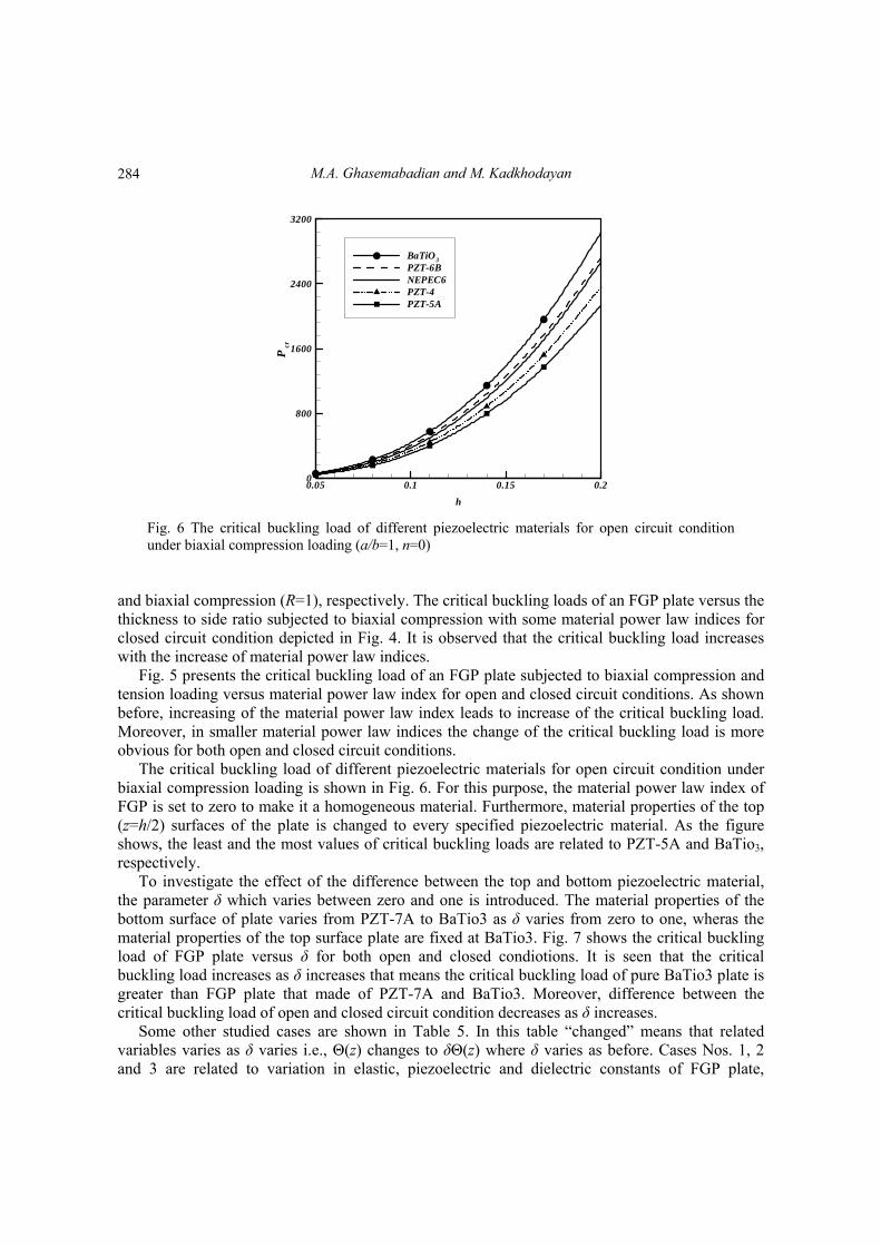
Fig. 6 The critical buckling load of different piezoelectric materials for open circuit condition under biaxial compression loading (a/b=1, n=0)
and biaxial compression (R=1), respectively. The critical buckling loads of an FGP plate versus the thickness to side ratio subjected to biaxial compression with some material power law indices for closed circuit condition depicted in Fig. 4. It is observed that the critical buckling load increases with the increase of material power law indices.
Fig. 5 presents the critical buckling load of an FGP plate subjected to biaxial compression and tension loading versus material power law index for open and closed circuit conditions. As shown before, increasing of the material power law index leads to increase of the critical buckling load. Moreover, in smaller material power law indices the change of the critical buckling load is more obvious for both open and closed circuit conditions.
The critical buckling load of different piezoelectric materials for open circuit condition under biaxial compression loading is shown in Fig. 6. For this purpose, the material power law index of FGP is set to zero to make it a homogeneous material. Furthermore, material properties of the top (z=h/2) surfaces of the plate is changed to every specified piezoelectric material. As the figure shows, the least and the most values of critical buckling loads are related to PZT-5A and BaTio3, respectively.
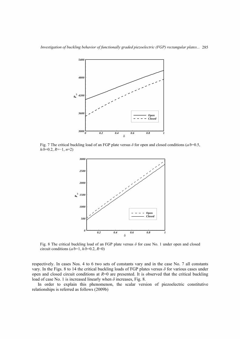
To investigate the effect of the difference between the top and bottom piezoelectric material, the parameter δ which varies between zero and one is introduced. The material properties of the bottom surface of plate varies from PZT-7A to BaTio3 as δ varies from zero to one, wheras the material properties of the top surface plate are fixed at BaTio3. Fig. 7 shows the critical buckling load of FGP plate versus δ for both open and closed condiotions. It is seen that the critical buckling load increases as δ increases that means the critical buckling load of pure BaTio3 plate is greater than FGP plate that made of PZT-7A and BaTio3. Moreover, difference between the critical buckling load of open and closed circuit condition decreases as δ increases.
Some other studied cases are shown in Table 5. In this table “changed” means that related variables varies as δ varies i.e., Θ(z) changes to δΘ(z) where δ varies as before. Cases Nos. 1, 2 and 3 are related to variation in elastic, piezoelectric and dielectric constants of FGP plate,
284
Investigation of buckling behavior of functionally graded piezoelectric (FGP) rectangular plates...
Pcr
0 0.2 0.4 0.6 0.8 13000
3600
4200
4800
5400
OpenClosed
Fig. 7 The critical buckling load of an FGP plate versus δ for open and closed conditions (a/b=0.5, h/b=0.2, R=−1, n=2)
Pcr
0.2 0.4 0.6 0.8 10
500
1000
1500
2000
2500
3000
OpenClosed
Fig. 8 The critical buckling load of an FGP plate versus δ for case No. 1 under open and closed circuit conditions (a/b=1, h/b=0.2, R=0)
respectively. In cases Nos. 4 to 6 two sets of constants vary and in the case No. 7 all constants vary. In the Figs. 8 to 14 the critical buckling loads of FGP plates versus δ for various cases under open and closed circuit conditions at R=0 are presented. It is observed that the critical buckling load of case No. 1 is increased linearly when δ increases, Fig. 8.
In order to explain this phenomenon, the scalar version of piezoelectric constitutive relationships is referred as follows (2009b)
285
M.A. Ghasemabadian and M. Kadkhodayan
σ Cε eE, (19a)
D eε ΞE. (19b)
Substituting (19b) into (19a) gives
2
σ C εΞ Ξ
e eD
(20)
For open circuit condition, electric displacement field is zero, hence Eq. (20) is reduced to
2
σ C εΞ
e
(21)
Introducing 2
CΞ
e as equivalent stiffness of open circuit condition, it can be seen that by
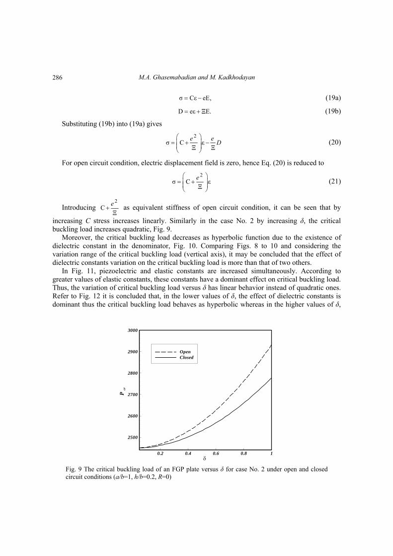
increasing C stress increases linearly. Similarly in the case No. 2 by increasing δ, the critical buckling load increases quadratic, Fig. 9.
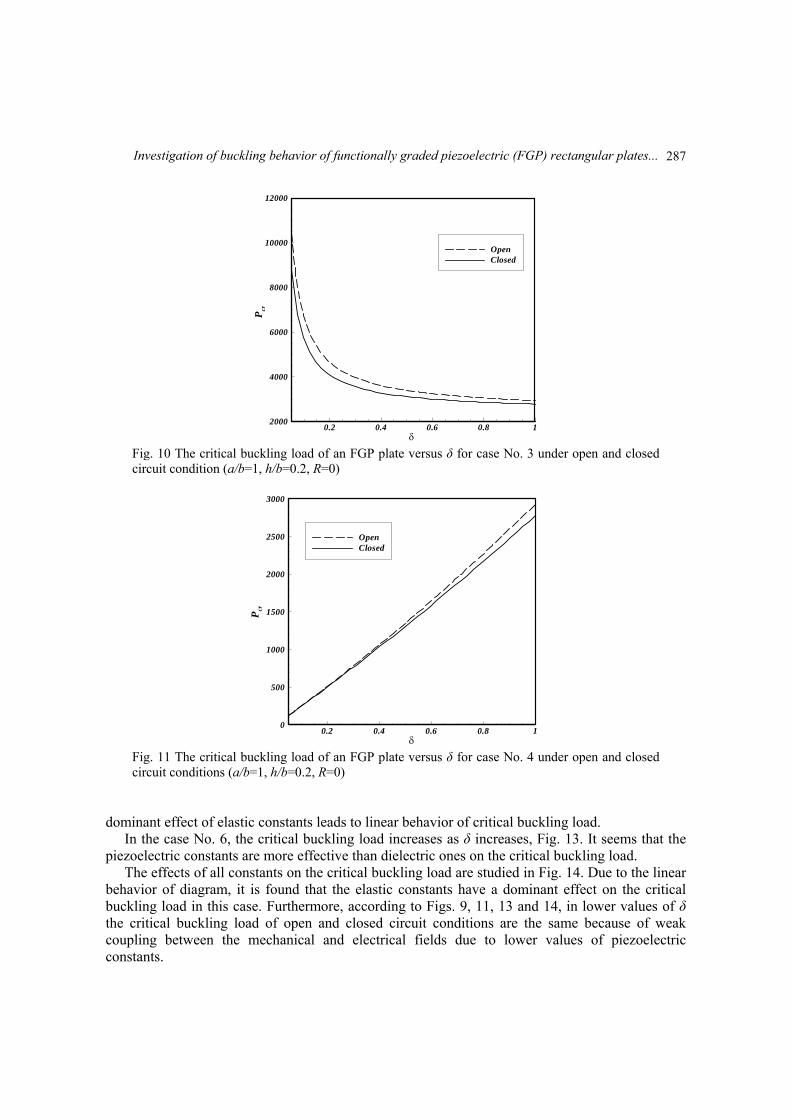
Moreover, the critical buckling load decreases as hyperbolic function due to the existence of dielectric constant in the denominator, Fig. 10. Comparing Figs. 8 to 10 and considering the variation range of the critical buckling load (vertical axis), it may be concluded that the effect of dielectric constants variation on the critical buckling load is more than that of two others.
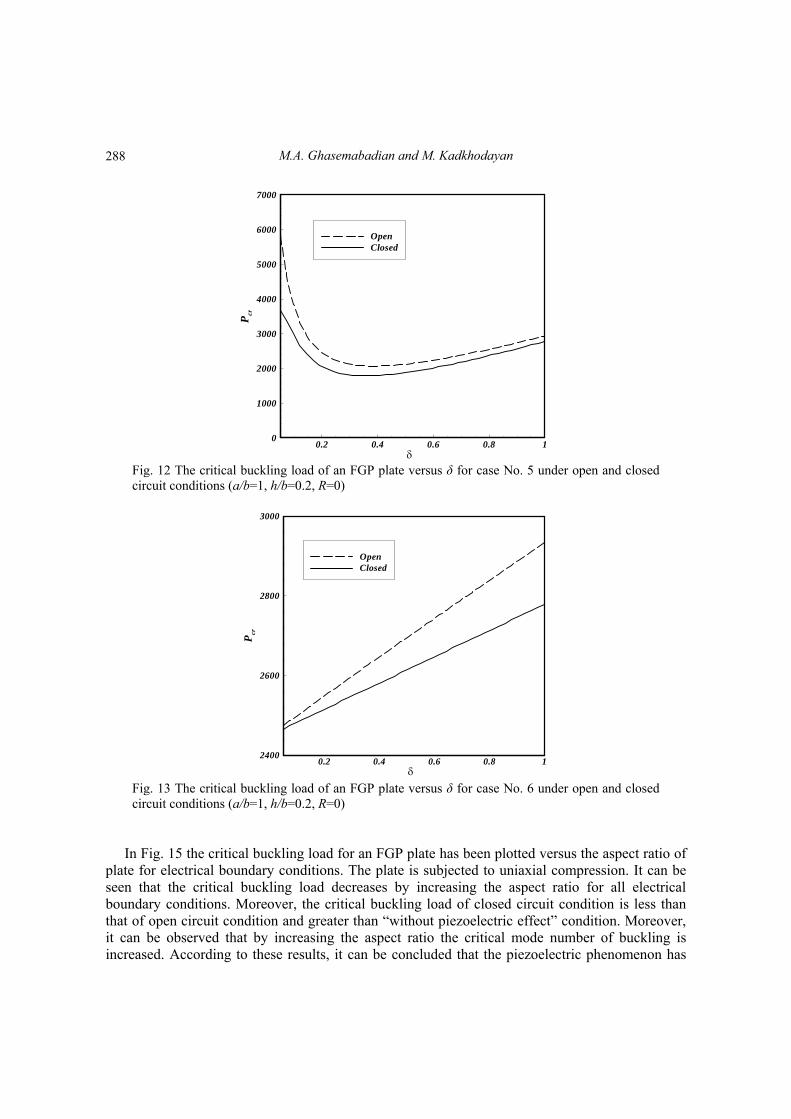
In Fig. 11, piezoelectric and elastic constants are increased simultaneously. According to greater values of elastic constants, these constants have a dominant effect on critical buckling load. Thus, the variation of critical buckling load versus δ has linear behavior instead of quadratic ones. Refer to Fig. 12 it is concluded that, in the lower values of δ, the effect of dielectric constants is dominant thus the critical buckling load behaves as hyperbolic whereas in the higher values of δ,
Pcr
0.2 0.4 0.6 0.8 1
2500
2600
2700
2800
2900
3000
OpenClosed
Fig. 9 The critical buckling load of an FGP plate versus δ for case No. 2 under open and closed circuit conditions (a/b=1, h/b=0.2, R=0)
286
Investigation of buckling behavior of functionally graded piezoelectric (FGP) rectangular plates...
Pcr
0.2 0.4 0.6 0.8 12000
4000
6000
8000
10000
12000
OpenClosed
Fig. 10 The critical buckling load of an FGP plate versus δ for case No. 3 under open and closed circuit condition (a/b=1, h/b=0.2, R=0)
Pcr
0.2 0.4 0.6 0.8 10
500
1000
1500
2000
2500
3000
OpenClosed
Fig. 11 The critical buckling load of an FGP plate versus δ for case No. 4 under open and closed circuit conditions (a/b=1, h/b=0.2, R=0)
dominant effect of elastic constants leads to linear behavior of critical buckling load. In the case No. 6, the critical buckling load increases as δ increases, Fig. 13. It seems that the
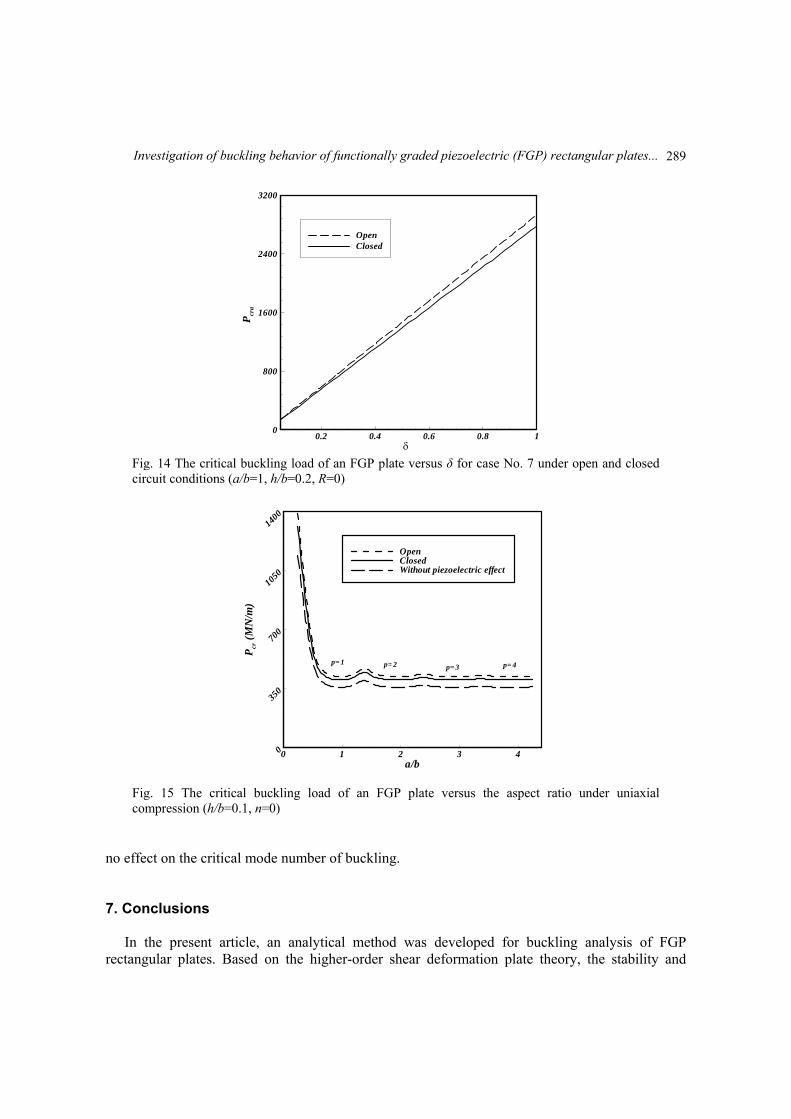
piezoelectric constants are more effective than dielectric ones on the critical buckling load. The effects of all constants on the critical buckling load are studied in Fig. 14. Due to the linear
behavior of diagram, it is found that the elastic constants have a dominant effect on the critical buckling load in this case. Furthermore, according to Figs. 9, 11, 13 and 14, in lower values of δ the critical buckling load of open and closed circuit conditions are the same because of weak coupling between the mechanical and electrical fields due to lower values of piezoelectric constants.
287
M.A. Ghasemabadian and M. Kadkhodayan
Pcr
0.2 0.4 0.6 0.8 10
1000
2000
3000
4000
5000
6000
7000
OpenClosed
Fig. 12 The critical buckling load of an FGP plate versus δ for case No. 5 under open and closed circuit conditions (a/b=1, h/b=0.2, R=0)
Pcr
0.2 0.4 0.6 0.8 12400
2600
2800
3000
OpenClosed
Fig. 13 The critical buckling load of an FGP plate versus δ for case No. 6 under open and closed circuit conditions (a/b=1, h/b=0.2, R=0)
In Fig. 15 the critical buckling load for an FGP plate has been plotted versus the aspect ratio of plate for electrical boundary conditions. The plate is subjected to uniaxial compression. It can be seen that the critical buckling load decreases by increasing the aspect ratio for all electrical boundary conditions. Moreover, the critical buckling load of closed circuit condition is less than that of open circuit condition and greater than “without piezoelectric effect” condition. Moreover, it can be observed that by increasing the aspect ratio the critical mode number of buckling is increased. According to these results, it can be concluded that the piezoelectric phenomenon has
288
Investigation of buckling behavior of functionally graded piezoelectric (FGP) rectangular plates...
Pcr
a
0.2 0.4 0.6 0.8 10
800
1600
2400
3200
OpenClosed
Fig. 14 The critical buckling load of an FGP plate versus δ for case No. 7 under open and closed circuit conditions (a/b=1, h/b=0.2, R=0)
a/b
Pcr
(MN
/m)
0 1 2 3 40
350
700
1050
1400
OpenClosedWithout piezoelectric effect
p= 1 p= 2 p= 3 p= 4
Fig. 15 The critical buckling load of an FGP plate versus the aspect ratio under uniaxial compression (h/b=0.1, n=0)
no effect on the critical mode number of buckling. 7. Conclusions
In the present article, an analytical method was developed for buckling analysis of FGP rectangular plates. Based on the higher-order shear deformation plate theory, the stability and
289
M.A. Ghasemabadian and M. Kadkhodayan
equilibrium equations were derived. Six coupled stability equations were solved using double sine series solution. The critical buckling loads for fully simply-supported boundary condition and closed and open circuit electrical boundary conditions were presented. From the numerical results the following conclusions are emphasized:
1. The electrical effect of FGPM increases the critical buckling load for both open and closed circuit conditions. 2. The critical buckling load increases as the thickness of FGP plate increases for all electrical and loading conditions, the critical buckling load increases as the thickness of FGP plate increases. 3. In all loading conditions, changing the open circuit condition to the closed one reduces the critical buckling loads. 4. In all electrical boundary conditions, the highest and lowest values for the critical buckling load are related to the plates under biaxial compression, and tension and biaxial compression, respectively. 5. The effect of variation in dielectric constants on the critical buckling load is more significant than that of other constants of FGPM. 6. The piezoelectric phenomenon has no effect on the critical mode number of buckling.
References Abdollahi, M., Saidi, A. and Mohammadi, M. (2015), “Buckling analysis of thick functionally graded
piezoelectric plates based on the higher-order shear and normal deformable theory”, Acta Mechanica, 226(8), 1-14.
Akbarov, S.D. and Yahnioglu, N. (2013a), “Buckling delamination of a sandwich plate-strip with piezoelectric face and elastic core layers”, Appl. Math. Model., 37(16), 8029-8038.
Akgöz, B. and Civalek, Ö. (2014a), “Thermo-mechanical buckling behavior of functionally graded microbeams embedded in elastic medium”, Int. J. Eng. Sci., 85, 90-104.
Akhras, G. and Li, W. (2010a), “Three-dimensional thermal buckling analysis of piezoelectric antisymmetric angle-ply laminates using finite layer method”, Compos. Struct., 92(1), 31-38.
Batra, R. and Geng, T. (2001a), “Enhancement of the dynamic buckling load for a plate by using piezoceramic actuators”, Smart Mater. Struct., 10(5), 925-933.
Bodaghi, M. and Saidi, A. (2010b), “Levy-type solution for buckling analysis of thick functionally graded rectangular plates based on the higher-order shear deformation plate theory”, Appl. Math. Model., 34(11), 3659-3673.
Brush, D.O. and Almroth, B. (1979), Buckling of Bars, Plates, and Shells, McGraw-Hill, New York. Chandrashekhara, K. and Bhatia, K. (1993), “Active buckling control of smart composite plates-finite-
element analysis”, Smart Mater. Struct., 2(1), 31-39. Civalek, Ö. (2004a), “Application of differential quadrature (DQ) and harmonic differential quadrature
(HDQ) for buckling analysis of thin isotropic plates and elastic columns”, Eng. Struct., 26(2), 171-186. Civalek, Ö., Korkmaz, A. and Demir, Ç. (2010c), “Discrete singular convolution approach for buckling
analysis of rectangular Kirchhoff plates subjected to compressive loads on two-opposite edges”, Adv. Eng. Softw., 41(4), 557-560.
Ebrahimi, F., Rastgoo, A. and Atai, A. (2009a), “A theoretical analysis of smart moderately thick shear deformable annular functionally graded plate”, Euro. J. Mech. A/Solid., 28(5), 962-973.
Fereidoon, A., Yaghoobi, H. and Dehghanian, A. (2014b), “An analytical approach for buckling behavior of temperature-dependent laminated piezoelectric functionally graded plates under thermo-electro-mechanical loadings and different end supports”, Int. J. Comput. Meth., 11(04), 1350099.
290
Investigation of buckling behavior of functionally graded piezoelectric (FGP) rectangular plates...
Hosseini-Hashemi, S., Khorshidi, K. and Amabili, M. (2008a), “Exact solution for linear buckling of rectangular Mindlin plates”, J. Sound Vib., 315(1), 318-342.
Jadhav, P. and Bajoria, K. (2013b), “Stability analysis of piezoelectric FGM plate subjected to electro-mechanical loading using finite element method”, Int. J. Appl. Sci. Eng., 11(4), 375-391.
Jalili, N. (2009b), Piezoelectric-based vibration control: from macro to micro/nano scale systems, Springer Science & Business Media.
Javaheri, R. and Eslami, M. (2002a), “Thermal buckling of functionally graded plates”, AIAA J., 40(1), 162-169.
Javaheri, R. and Eslami, M. (2002b), “Thermal buckling of functionally graded plates based on higher order theory”, J. Therm. Stress., 25(7), 603-625.
Jones, R.M. (2006a), Buckling of bars, plates, and shells, Bull Ridge Corporation. Kapuria, S. and Achary, G. (2006b), “Nonlinear coupled zigzag theory for buckling of hybrid piezoelectric
plates”, Compos. Struct., 74(3), 253-264. Kim, G.W. and Lee, K.Y. (2008b), “Influence of weak interfaces on buckling of orthotropic piezoelectric
rectangular laminates”, Compos. Struct., 82(2), 290-294. Kim, S.E., Thai, H.T. and Lee, J. (2009c), “Buckling analysis of plates using the two variable refined plate
theory”, Thin Wall. Struct., 47(4), 455-462. Kuo, S.R. and Yau, J. (2012), “Buckling equations of orthotropic thin plates”, J. Mech., 28(03), 555-567. Lanhe, W. (2004b), “Thermal buckling of a simply supported moderately thick rectangular FGM plate”,
Compos. Struct., 64(2), 211-218. Mirzavand, B. and Eslami, M. (2011a), “A closed-form solution for thermal buckling of piezoelectric FGM
rectangular plates with temperature-dependent properties”, Acta Mechanica, 218(1-2), 87-101. Mohammadi, M., Saidi, A. and Jomehzadeh, E. (2010d), “A novel analytical approach for the buckling
analysis of moderately thick functionally graded rectangular plates with two simply-supported opposite edges”, Proceedings of the Institution of Mechanical Engineers, Part C: Journal of Mechanical Engineering Science, 224(9), 1831-1841.
Mohammadi, M., Saidi, A.R. and Jomehzadeh, E. (2010e), “Levy solution for buckling analysis of functionally graded rectangular plates”, Appl. Compos. Mater., 17(2), 81-93.
Panahandeh-Shahraki, D., Mirdamadi, H.R. and Vaseghi, O. (2014c), “Fully coupled electromechanical buckling analysis of active laminated composite plates considering stored voltage in actuators”, Compos. Struct., 118, 94-105.
Rad, A.A. and Panahandeh-Shahraki, D. (2014d), “Buckling of cracked functionally graded plates under tension”, Thin Wall. Struct., 84, 26-33.
Shariat, B.S. and Eslami, M. (2007), “Buckling of thick functionally graded plates under mechanical and thermal loads”, Compos. Struct., 78(3), 433-439.
Shariyat, M. (2009d), “Dynamic buckling of imperfect laminated plates with piezoelectric sensors and actuators subjected to thermo-electro-mechanical loadings, considering the temperature-dependency of the material properties”, Compos. Struct., 88(2), 228-239.
Shariyat, M. (2009e), “Vibration and dynamic buckling control of imperfect hybrid FGM plates with temperature-dependent material properties subjected to thermo-electro-mechanical loading conditions”, Compos. Struct., 88(2), 240-252.
Shen, H.S. (2001b), “Postbuckling of shear deformable laminated plates with piezoelectric actuators under complex loading conditions”, Int. J. Solid. Struct., 38(44), 7703-7721.
Shen, H.S. (2001c), “Thermal postbuckling of shear-deformable laminated plates with piezoelectric actuators”, Compos. Sci. Tech., 61(13), 1931-1943.
Shen, H.S. (2005), “Postbuckling of FGM plates with piezoelectric actuators under thermo-electro-mechanical loadings”, Int. J. Solid. Struct., 42(23), 6101-6121.
Shen, H.S. (2009f), “A comparison of buckling and postbuckling behavior of FGM plates with piezoelectric fiber reinforced composite actuators”, Compos. Struct., 91(3), 375-384.
Sheng, G. and Wang, X. (2010f), “Thermoelastic vibration and buckling analysis of functionally graded piezoelectric cylindrical shells”, Appl. Math. Model., 34(9), 2630-2643.
291

M.A. Ghasemabadian and M. Kadkhodayan
Varelis, D. and Saravanos, D.A. (2004c), “Coupled buckling and postbuckling analysis of active laminated piezoelectric composite plates”, Int. J. Solid. Struct., 41(5), 1519-1538.
Yang, Y. (1998), “Buckling of a piezoelectric plate”, Int. J. Appl. Electromag. Mech., 9(40), 399-408. Yoo, C.H. and Lee, S. (2011b), Stability of structures: principles and applications, Elsevier. PL
292
Investigation of buckling behavior of functionally graded piezoelectric (FGP) rectangular plates...
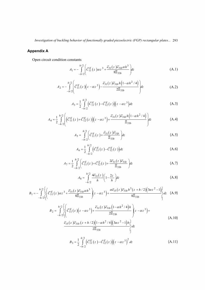
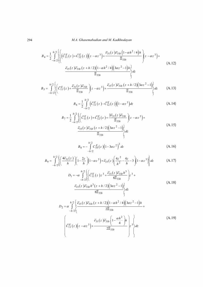
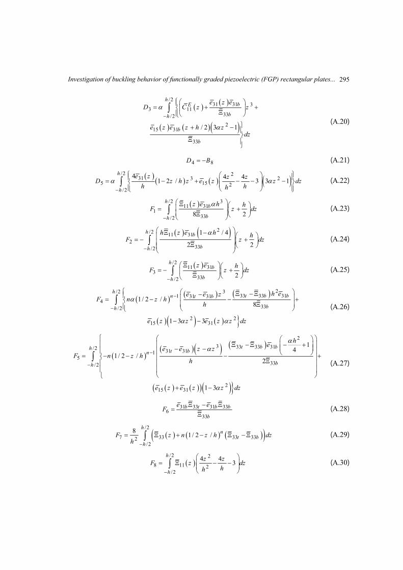
Appendix A
Open circuit condition constants
/2 331 313
1 1133/2
8
hbE
bh
z hA C z z
ed
ez
(A.1)
2/2 31 3132 11
33/2
1 / 4
2
h bE
bh
z h hA C z
ez z dz
e
(A.2)
/2
33 11 12
/2
1
2
hE E
h
A C z C z z z dz
(A.3)
2/2 31 3134 11 12
33/2
1 / 41
2
h bE E
bh
z h hA C z C z z z d
ez
e
(A.4)
/231 31
5 1133/2
hbE
bh
zA C z
ez
ed
(A.5)
/2
6 11 12/2
1
2
hE E
h
A C z C z dz
(A.6)
/231 31
7 11 1233/2
21
2
hbE E
bh
zA C z C z
e edz
(A.7)
/231
8/2
4 21
h
h
z zA dz
h h
e
(A.8)
3 2/2 3 15 3131 313 31 11
33 33/2
/ 2 3 1
8 8
h bbE
b bh
z h z h zz hB C z z z
e ee ez dz
(A.9)
2/2 31 313 32 11
33/2
2 215 31
33
1 / 4
2
/ 2 1 / 4 3 1
2
h bE
bh
b
b
z h hB C z z z z z
z z h h z h
e e
edz
e
(A.10)
/2 23
3 11 12/2
1
2
hE E
h
B C z C z z z dz
(A.11)
293
M.A. Ghasemabadian and M. Kadkhodayan
2/2 31 313 34 11 12
33/2
2 215 31
33
1 / 41
2
/ 2 1 / 4 3 1
h bE E
bh
b
b
z h hB C z C z z z z z
z z h h z hd
e e
ez
e
(A.12)
2/2 15 3131 31 35 11
33 33/2
/ 2 3 1h bbE
b bh
z z h zzB C z z z
e ee edz
(A.13)
/2
36 11 12
/2
11
2
hE E
h
B C z C z z dz
(A.14)
/231 31 3
7 11 1233/2
215 31
33
21
2
/ 2 3 1
hbE E
bh
b
b
e zB C z C z z z
z z h zd
e
ze e
(A.15)
/2 22
8 55/2
1 3h
E
h
B C z z dz
(A.16)
/2 2
31 3 39 15 2
/2
4 2 4 41 1 3 1
h
h
ee
z z z zB z z z dz
h h hh
(A.17)
/2 331 313 3
1133/2
3 215 31
33
1 8
/ 2 3 1
8
hbE
bh
b
b
z hD C z z z
z h z h
e e
ze e z
d
(A.18)
2 2/2 15 31
33/2
2
31 313 3
113
2
3
/ 2 1 / 4 3 1
2
14
2
h b
bh
bE
b
z z h h z hD
hz h
C z
e e
e e
z z z dz
(A.19)
294
Investigation of buckling behavior of functionally graded piezoelectric (FGP) rectangular plates...
/231 31 3
11333/2
215 31
33
/ 2 3 1
hbE
bh
b
b
zD C z z
z z h
e
z
e
e e zd
(A.20)
4 8D B (A.21)
/2 2
31 3 25 15 2
/2
4 4 41 2 / 3 3 1
h
h
z z zD z h z z z dz
h hh
ee
(A.22)
/2 311 31
133/2
8 2
hb
bh
z h hd
eF z z
(A.23)
2/2 11 312
33/2
1 / 4
2 2
h b
bh
h z h hF z z
ed
(A.24)
/211 31
333/2
2
hb
bh
z hF z dz
e
(A.25)
2/2 333 33 311 31 31
433/2
2 215 31
1 / 2 /8
1 3 3
ht b bn t b
bh
hzF n z h
h
z z z z dz
ee e
e e
(A.26)
2
3 33 33 31/2 31 3115
33/2
215 31
14
1/ 2 /2
1 3
t b bh t bn
bh
hz z
F n z hh
z z
ee e
e e z dz
(A.27)
31 33 31 336
33
b t b b
b
e eF
(A.28)
/2
7 33 33 332/2
81/ 2 /
hn
t bh
F z n z h dzh
(A.29)
/2 2
8 11 2/2
4 43
h
h
z zF z dz
hh
(A.30)
295
M.A. Ghasemabadian and M. Kadkhodayan
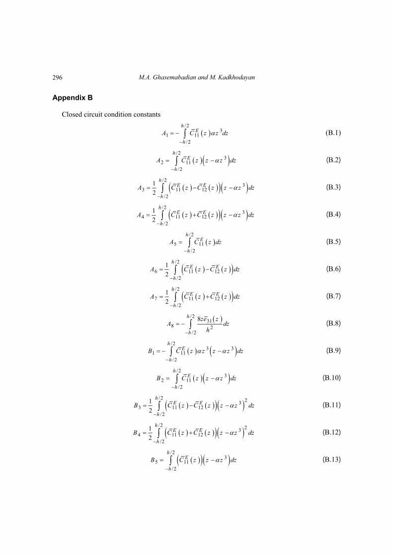
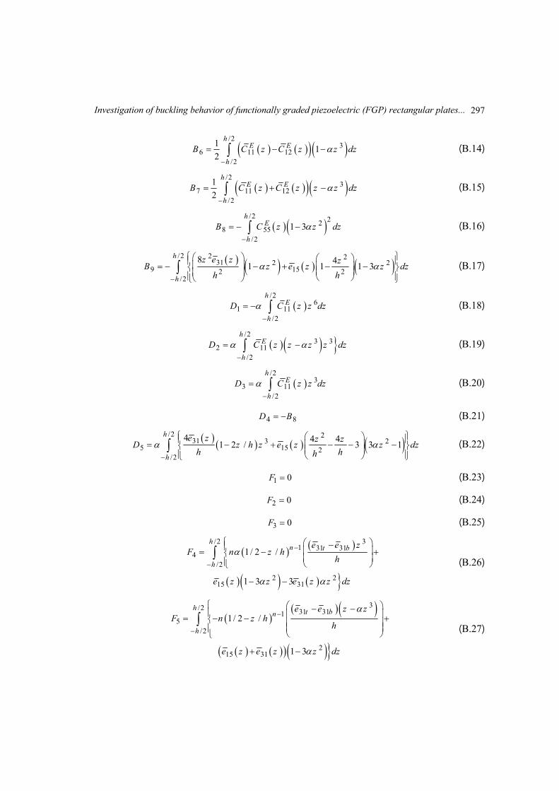
Appendix B
Closed circuit condition constants
/2
31 11
/2
hE
h
A C z z dz
(B.1)
/2
32 11
/2
hE
h
A C z z z dz
(B.2)
/2
33 11 12
/2
1
2
hE E
h
A C z C z z z dz
(B.3)
/2
34 11 12
/2
1
2
hE E
h
A C z C z z z dz
(B.4)
/2
5 11/2
hE
h
A C z dz
(B.5)
/2
6 11 12/2
1
2
hE E
h
A C z C z dz
(B.6)
/2
7 11 12/2
1
2
hE E
h
A C z C z dz
(B.7)
/231
8 2/2
8h
h
z zA
edz
h
(B.8)
/2
3 31 11
/2
hE
h
B C z z z z dz
(B.9)
/2
32 11
/2
hE
h
B C z z z dz
(B.10)
/2 23
3 11 12/2
1
2
hE E
h
B C z C z z z dz
(B.11)
/2 23
4 11 12/2
1
2
hE E
h
B C z C z z z dz
(B.12)
/2
35 11
/2
hE
h
B C z z z dz
(B.13)
296
Investigation of buckling behavior of functionally graded piezoelectric (FGP) rectangular plates...
/2
36 11 12
/2
11
2
hE E
h
B C z C z z dz
(B.14)
/2
37 11 12
/2
1
2
hE E
h
B C z C z z z dz
(B.15)
/2 22
8 55/2
1 3h
E
h
B C z z dz
(B.16)
/2 2 2
319 15
/2
22 2
28 41 1 1 3
h
h
z z zB z z z dz
h
e
he
(B.17)
/2
16
11/2
hE
h
D C z z dz
(B.18)
/2
3 311
/22
hE
h
D C z z z z dz
(B.19)
/2
311
/3
2
hE
h
D C z z dz
(B.20)
4 8D B (B.21)
/2 2
31 3 25 15 2
/2
4 4 41 2 / 3 3 1
h
h
z z zD z h z z z dz
h hh
ee
(B.22)
1 0F (B.23)
2 0F (B.24)
3 0F (B.25)
/2 31 31 31
4/2
2 215 31
1/ 2 /
1 3 3
hn t b
h
e e zF n z h
h
z z z z ze de
(B.26)
3/2 31 3115
/2
215 31
1/ 2 /
1 3
h t bn
h
z zF n z h
h
z z z de z
e e
e
(B.27)
297
M.A. Ghasemabadian and M. Kadkhodayan
6 31 31b bF e e (B.28)
/2
17 33 33 333
/2
81/ 2 /
hn
t bh
F h z n z h z dzh
(B.29)
/2 2
8 11 2/2
41
h
h
zF z dz
h
(B.30)
Appendix C
2 211 1k A (C.1)
12 8k A (C.2)
2 213 2 3k A A (C.3)
14 4k A (C.4)
2 215 5 6k A A (C.5)
16 7k A (C.6)
2 221 1k A (C.7)
22 8k A (C.8)
23 4k A (C.9)
2 224 3 2k A A (C.10)
25 7k A (C.11)
2 226 6 5k A A (C.12)
3 231 1 8k B B (C.13)
32 9k B (C.14)
2 233 2 3 8k B B B (C.15)
34 4k B (C.16)
298
Investigation of buckling behavior of functionally graded piezoelectric (FGP) rectangular plates...
2 235 5 6k B B (C.17)
36 7k B (C.18)
3 241 1 8k B B (C.19)
42 9k B (C.20)
43 4k B (C.21)
2 244 3 2 8k B B B (C.22)
45 7k B (C.23)
2 246 6 5k B B (C.24)
4 2 2 4 2 2 251 1 4 12k D D P (C.25)
2 252 5k D (C.26)
2 253 2 4k D D (C.27)
2 254 2 4k D D (C.28)
2 255 3k D (C.29)
2 256 3k D (C.30)
4 2 2 4 2 261 1 42k F F (C.31)
2 262 7 1k F (C.32)
2 263 2 5k F F (C.33)
2 264 2 5k F F (C.34)
2 265 3 6k F F (C.35)
2 266 3 6k F F (C.36)
299