Embed Size (px)
Citation preview
An electromechanical higher order model for piezoelectricfunctionally graded plates
S. M. Shiyekar • Tarun Kant
Received: 19 March 2010 / Accepted: 31 March 2010 / Published online: 23 April 2010
� Springer Science+Business Media, B.V. 2010
Abstract Bidirectional flexure analysis of function-
ally graded (FG) plate integrated with piezoelectric fiber
reinforced composites (PFRC) is presented in this paper.
A higher order shear and normal deformation theory
(HOSNT12) is used to analyze such hybrid or smart
FG plate subjected to electromechanical loading. The
displacement function of the present model is approx-
imated as Taylor’s series in the thickness coordinate,
while the electro-static potential is approximated as
layer wise linear through the thickness of the PFRC
layer. The equations of equilibrium are obtained using
principle of minimum potential energy and solution is
by Navier’s technique. Elastic constants are varying
exponentially along thickness (z axis) for FG material
while Poisson’s ratio is kept constant. PFRC actuator
attached either at top or bottom of FG plate and analyzed
under mechanical and coupled mechanical and electri-
cal loading. Comparison of present HOSNT12 is made
with exact and finite element method (FEM).
Keywords Higher order theory � Piezoelectric
fiber reinforced composites � Functionally Graded
1 Introduction
Piezoelectric materials transform elastic field into the
electric field and converse behavior leads many
researchers to study their controlling capabilities
applicable to structures like plates and shells. Such
structures are called as smart, intelligent, adaptive as
well as hybrid structures. In conventional composites
failure occurs at interface due to abrupt change in
material properties. Elastic properties are varying
smoothly across the thickness of the FG material and
hence failure due to de lamination is avoided.
Piezoelectric materials show coupling phenome-
non between elastic and electric fields. Tiersten and
Mindlin (1962) initiated work on piezoelectric plates.
Further Tiersten (1969) contributed this work by
exploring the governing equations of linear piezo-
electric continuum by analyzing vibrations of a single
piezoelectric layer.
Monolithic piezoelectric materials exhibit very low
stress/strain coefficients and hence low controlling
capabilities. Smith and Auld (1991) presented micro-
mechanical analysis of vertically reinforced piezo-
electric composites with slight increase in the stress/
strain piezoelectric coefficients.
Mallik and Ray (2003) proposed the concept of
unidirectional piezoelectric fiber reinforced composite
(PFRC) materials and presented their effective elastic
and piezoelectric properties. Piezoelectric stress/strain
coefficients are improved considerably as compared
to monolithic piezoelectric materials. Vertically
S. M. Shiyekar (&)
Department of Civil Engineering, Sinhgad College
of Engineering, Vadgaon (Bk), Pune 411 041, India
e-mail: [email protected]
T. Kant
Department of Civil Engineering, Indian Institute
of Technology Bombay, Powai 400 076, India
e-mail: [email protected]
123
Int J Mech Mater Des (2010) 6:163–174
DOI 10.1007/s10999-010-9124-4
reinforced piezoelectric composites are not suitable for
the bending mode actuation (Mallik and Ray 2003).
Many investigators studied hybrid composite lam-
inates using various plate theories. Kapuria and Dumir
(2000) presented coupled first-order shear deforma-
tion theory for hybrid laminated plates subjected to
thermoelectrical loading. Elasticity solutions always
serve as benchmark for other approximate solutions.
Ray et al. (1993) developed three-dimensional (3D)
elasticity solutions for intelligent plate simply sup-
ported and perfectly bonded with distributed Polyvi-
nylidene Fluoride (PVDF) piezoelectric layers at top
and bottom and presented static displacement control
for different span to depth ratios. Heyliger (1994)
obtained exact solution for an unsymmetric cross ply
composite laminate attached with PZT-4 layers of
piezoelectric material at upper and lower surfaces. The
3D solution methodology used by Ray and Heyliger is
the same as the work of Pagano (1970) for laminated
composite plates. Later Heyliger (1997) provided the
3D exact solution for single and two layers of
piezoelectric materials. Vel and Batra (2000) used
Eshelby-Stroh formulation to obtained 3D elasticity
solution to analyze multilayered piezoelectric plate for
arbitrary boundary conditions. Batra and Vel (2001)
presented exact thermo elastic solutions for FG plates,
while Sankar (2001) presented 3D exact solutions for
functionally graded beams under mechanical pressure.
Ray and Sachade (2006a, b) reported 3D elasticity
solution and FEM for FG plate attached with PFRC
actuator. Reddy and Cheng (2001) also presented
elasticity solutions for smart FG plate.
Higher order shear deformation theories (HOST)
incorporate transverse shear and normal deformation
by expanding the primary displacement fields. Initially
Kant (1982) developed complete set of variationally
consistent governing equations of equilibrium and
presented first FE model based on HOST (Kant et al.
1982). Pandya and Kant (1987, 1988) and Kant and
Manjunatha (1988, 1994) extended the HOST for
unsymmetric laminates. Further Kant and Swaminathan
(2002) presented a refined higher order theory and
discussed analytical solution for sandwiches and lam-
inates. Reddy (1984) presented a simple third order
theory for laminates maintaining zero shear stress
conditions at boundaries of the thickness dimension.
In this paper, a higher order shear and normal
deformation theory (HOSNT12) is used to model the
elastic displacements of FG plate whereas; electric
potential in the PFRC actuator layer is modeled as
piece wise linear.
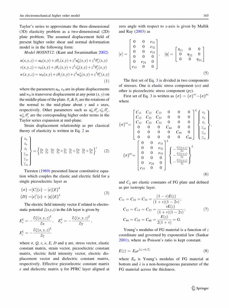
2 Formulation
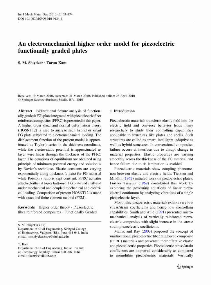
Consider bidirectional flexure of functionally graded
(FG) plate. At x = 0, a and at y = 0, b the FG plate is
simply supported and attached with distributed PFRC
actuator of thickness tp at top or bottom as shown in
the Fig. 1. Span of the hybrid FG plate is a along x
axis and b along y axis in Cartesian coordinate
system. Thickness of FG plate is h along z axis and
located at -h/2 and ?h/2 from bottom and top of FG
plate, respectively. Electrostatic potential is applied
at top of PFRC actuator (h/2 ? tp) and FG plate is
electrically grounded at z = ?h/2.
Displacement components u(x,y,z), v(x,y,z) and
w(x,y,z) at any point in the plate are expanded in a
x
z
u0
w0
yh
Simple (Diaphragm) Supports
Functionally graded plate
Piezoelectric Fiber Reinforced Composite (PFRC) Layer
a
tp
Fig. 1 Geometry of
Functionally Graded (FG)
simply (diaphragm)
supported along all edges
plate attached with PFRC
actuator
164 S. M. Shiyekar, T. Kant
123
Taylor’s series to approximate the three-dimensional
(3D) elasticity problem as a two-dimensional (2D)
plate problem. The assumed displacement field of
present higher order shear and normal deformation
model is in the following form:
Model HOSNT12: (Kant and Swaminathan 2002)
uðx;y;zÞ¼ u0ðx;yÞþzhxðx;yÞþz2u�0ðx;yÞþz3h�xðx;yÞvðx;y;zÞ¼ v0ðx;yÞþzhyðx;yÞþ z2v�0ðx;yÞþ z3h�yðx;yÞwðx;y;zÞ¼ w0ðx;yÞþzhzðx;yÞþz2w�0ðx;yÞþz3h�z ðx;yÞ
ð1Þ
where the parameters u0, v0 are in-plane displacements
and w0 is transverse displacement at any point (x, y) on
the middle plane of the plate. hx & hy are the rotations of
the normal to the mid-plane about y and x axes,
respectively. Other parameters such as u�0;h�x ;v�0;h�y ;
w�0;h�z are the corresponding higher order terms in the
Taylor series expansion at mid-plane.
Strain displacement relationship as per classical
theory of elasticity is written in Eq. 2 as
ex
ey
ez
cxy
cyz
cxz
8>>>>>><
>>>>>>:
9>>>>>>=
>>>>>>;
¼ ouox
ovoy
owoz
ouoyþ ov
oxovozþ ow
oyouozþ ow
ox
n otð2Þ
Tiersten (1969) presented linear constitutive equa-
tion which couples the elastic and electric field for a
single piezoelectric layer as
frg ¼½C�feg � ½e�fEgL
fDg ¼½e�tfeg þ ½g�fEgLð3Þ
The electric field intensity vector E related to electro-
static potential n(x,y,z) in the Lth layer is given by
ELx ¼ �
onðx; y; zÞL
ox; EL
y ¼ �onðx; y; zÞL
oy;
ELz ¼ �
onðx; y; zÞL
oz
where r, Q, e, e, E, D and g are, stress vector, elastic
constant matrix, strain vector, piezoelectric constant
matrix, electric field intensity vector, electric dis-
placement vector and dielectric constant matrix,
respectively. Effective piezoelectric constant matrix
e and dielectric matrix g for PFRC layer aligned at
zero angle with respect to x-axis is given by Mallik
and Ray (2003) as
e½ � ¼
0 0 e31
0 0 e32
0 0 e33
0 0 0
0 e24 0
e15 0 0
2
6666664
3
7777775
; g½ � ¼g11 0 0
0 g22 0
0 0 g33
2
4
3
5
ð5ÞThe first set of Eq. 3 is divided in two components
of stresses. One is elastic stress component (es) and
other is piezoelectric stress component (pz).
First set of Eq. 3 is written as rf g ¼ rf ges� rf gpz
where
rf ges¼
C11 C12 C13 0 0 0
C12 C22 C23 0 0 0
C13 C23 C33 0 0 0
0 0 0 C44 0 0
0 0 0 0 C55 0
0 0 0 0 0 C66
2
6666664
3
7777775
L ex
ey
ez
cxy
cyz
cxz
8>>>>>><
>>>>>>:
9>>>>>>=
>>>>>>;
;
rf gpz¼
0 0 e31
0 0 e32
0 0 e33
0 0 0
0 e24 0
e15 0 0
2
6666664
3
7777775
L
� onðx;y;zÞox
� onðx;y;zÞoy
� onðx;y;zÞoz
8><
>:
9>=
>;
L
ð6Þ
and Cij are elastic constants of FG plate and defined
as per isotropic layer.
C11 ¼ C22 ¼ C33 ¼ð1� mÞEðzÞð1þ mÞð1� 2mÞ ;
C12 ¼ C13 ¼ C23 ¼mEðzÞ
ð1þ mÞð1� 2mÞ ;
C44 ¼ C55 ¼ C66 ¼EðzÞ
2ð1þ mÞ ¼ G:
ð7Þ
Young’s modulus of FG material is a function of z
coordinate and governed by exponential law (Sankar
2001), where as Poisson’s ratio is kept constant.
E zð Þ ¼ E0ekðzþh=2Þ ð8Þ
where E0 is Young’s modulus of FG material at
bottom and k is a non-homogeneous parameter of the
FG material across the thickness.
An electromechanical higher order model 165
123
Stress resultants are also defined as elastic and
piezoelectric stress resultants.
Elastic stress resultants [Q, S, M, N]es
Qesx ;Q
esy jQes�
x ;Qes�
y
h i
¼Xn
L¼1
Zþh=2
�h=2
sesxz; s
esyz
n o1jz2� �
dz; Sesx ; S
esy jSes�
x ; Ses�
y
h i
¼Xn
L¼1
Zþh=2
�h=2
sesxz; s
esyz
n ozjz3� �
dz
Mesx ;M
esy ;M
esxyjMes�
x ;Mes�
y ;Mes�
xy
h i
¼Xn
L¼1
Zþh=2
�h=2
resx ; r
esy ; s
esxy
n ozjz3� �
dz;Mesz
¼Xn
L¼1
Zþh=2
�h=2
rezdz;
Nesx ;N
esy ;N
esz ;N
esxyjNes�
x ;Nes�
y ;Nes�
z ;Nes�
xy
h i
¼Xn
L¼1
Zþh=2
�h=2
resx ; r
esy ; r
esz ; s
esxy
n o1jz2� �
dz: ð9Þ
Piezoelectric stress resultants [Q, S, M, N]pz
Qpzx ;Q
pzy jQpz�
x ;Qpz�
y
h i
¼Zh=2þtp
þh=2
spzxz ; s
pzyz
n o1jz2� �
dz; Spzx ; S
pzy jSpz�
x ; Spz�
y
h i
¼Zh=2þtp
þh=2
spzxz ; s
pzyz
n ozjz3� �
dz
Mpzx ;M
pzy ;M
pzxy jMpz�
x ;Mpz�
y ;Mpz�
xy
h i
¼Zh=2þtp
þh=2
rpzx ; r
pzy ; s
pzxy
n ozjz3� �
dz;Mpzz ¼
Zh=2þtp
þh=2
rpzz dz;
Npzx ;N
pzy ;N
pzz ;N
pzxy jNpz�
x ;Npz�
y ;Npz�
z ;Npz�
xy
h i
¼Zh=2þtp
þh=2
rpzx ; r
pzy ; r
pzz ; s
pzxy
n o1jz2� �
dz: ð10Þ
Total stress resultants (pz): Total stress resultants
[Q, S, M, N] are algebraic sum of elastic and piezo-
electric stress resultants.
½Q; S;M;N� ¼ ½Q; S;M;N�es þ ½Q; S;M;N�pz ð11ÞGoverning equations of equilibrium.
Using principal of minimum potential energy, the
equations of equilibrium are obtained as
du0 :oNx
oxþ oNxy
oy¼ 0 du�0 :
oN�xoxþ
oN�xy
oy� 2Sx ¼ 0
dv0 :oNy
oyþ oNxy
ox¼ 0 dv�0 :
oN�yoyþ
oN�xy
ox� 2Sy ¼ 0
dw0 :oQx
oxþ oQy
oyþ ðqþz Þ ¼ 0 dw�
0:oQ�xoxþ
oQ�yoy� 2M�z þ
h2
4ðqþz Þ ¼ 0
dhx :oMx
oxþ oMxy
oy� Q
x¼ 0 dh�x :
oM�xoxþ
oM�xy
oy� 3Q�x ¼ 0
dhy :oMy
oyþ oMxy
ox� Qy ¼ 0 dh�y :
oM�yoyþ
oM�xy
ox� 3Q�y ¼ 0
dhz :oSx
oxþ oSy
oy� Nz þ
h
2ðqþz Þ ¼ 0 dh�z :
oSx
oxþ oSy
oy� 3N�z þ
h3
8ðqþz Þ ¼ 0
ð12Þ
166 S. M. Shiyekar, T. Kant
123
Total stress resultants are the addition of elastic
and piezoelectric stress resultants.
Following are the mechanical boundary conditions
used for simply supported plate
At edges x ¼ 0 and x ¼ a :
v0 ¼ 0; w0 ¼ 0; hy ¼ 0; hz ¼ 0;
Mx ¼ 0; Nx ¼ 0; v�0 ¼ 0; w�0 ¼ 0;
h�y ¼ 0; h�z ¼ 0; M�x ¼ 0; N�x ¼ 0:
At edges y ¼ 0 and y ¼ b :
u0 ¼ 0; w0 ¼ 0; hx ¼ 0; hz ¼ 0;
My ¼ 0; Ny ¼ 0; u�0 ¼ 0; w�0 ¼ 0;
h�x ¼ 0; h�z ¼ 0; M�y ¼ 0; N�y ¼ 0:
ð13Þ
Navier’s solution procedure is adopted to find the
solution of displacement variables, satisfying the
above boundary conditions and is expressed as follows:
where qþz is the mechanical loading term and n(x, z) is
the electrical loading term. Through thickness electric
potential nmnðzÞ is assumed as per the following.
The elastic FG layer is attached with distributed
actuator layer of PFRC. The thickness of the PFRC
layer is small as compared to the thickness of the
substrate, the electro-static potential in the actuator
layer is assumed to be linear through the thickness of
the PFRC layer.
nmnðzÞ ¼Vt
mn
tp
� �
z� Vtmnh
2tp
� �
ð15Þ
Equation 15 gives linear variation of thought thick-
ness electro-static potential in the PFRC actuating layer.
Vtmn represents amplitude of doubly sinusoidal electro-
static potential applied at top of the PFRC whereas; h
and tp are thicknesses of elastic FG plate and PFRC
layer, respectively. Assumed electrostatic potential
satisfies zero electric potential at interface. Similar
electrostatic potential can be assumed for PFRC layer
at bottom of FG plate.
The piezoelectric stress vectors are calculated
from second set of Eq. 6 by substituting actuating
electric function (Eq. 15) when either top or bottom
voltages (Vtmn, Vb
mn) are applied. Finally, piezoelectric
stress resultants are evaluated from Eq. 10. Similarly
elastic stress vectors and elastic stress resultants are
calculated from first set of Eqs. 6 and 9, respectively.
Displacement terms are obtained by solving linear
algebraic equations by substituting total stress resul-
tants from Eq. 11 in a set of equilibrium equations
(Eq. 12).
u0 ¼X1
m¼1
X1
n¼1
u0mncos
mpx
a
� �sin
npy
b
� �u�
0¼X1
m¼1
X1
n¼1
u�0mncos
mpx
a
� �sin
npy
b
� �
v0 ¼X1
m¼1
X1
n¼1
v0mnsin
mpx
a
� �cos
npy
b
� �v�
0¼X1
m¼1
X1
n¼1
v�0mnsin
mpx
a
� �cos
npy
b
� �
w0 ¼X1
m¼1
X1
n¼1
w0mnsin
mpx
a
� �sin
npy
b
� �w�0 ¼
X1
m¼1
X1
n¼1
w�0mnsin
mpx
a
� �sin
npy
b
� �
hx ¼X1
m¼1
X1
n¼1
hxmncos
mpx
a
� �sin
npy
b
� �h�x ¼
X1
m¼1
X1
n¼1
hxmn� cos
mpx
a
� �sin
npy
b
� �
hy ¼X1
m¼1
X1
n¼1
hymnsin
mpx
a
� �cos
npy
b
� �h�y ¼
X1
m¼1
X1
n¼1
h�ymnsin
mpx
a
� �cos
npy
b
� �
hz ¼X1
m¼1
X1
n¼1
hzmnsin
mpx
a
� �sinðnpy
bÞ h�z ¼
X1
m¼1
X1
n¼1
h�zmnsin
mpx
a
� �sin
npy
b
� �
qþz ¼X1
m¼1
X1
n¼1
qþzmnsin
mpx
a
� �sin
npy
b
� �nðx; zÞ ¼
X1
m¼1
X1
n¼1
nmnðzÞ sinmpx
a
� �sin
npy
b
� �
ð14Þ
An electromechanical higher order model 167
123
3 Numerical results and discussions
Numerical evaluation of a FG plate attached with
piezoelectric layer either at top or at bottom is considered.
Property of piezoelectric fiber reinforced composite is
taken as follows (Ray and Sachade 2006b).
FG Material: E0 = 200 GPa and m = 0.3.
PFRC (PZT5H): C11 = 32.6 GPa, C11 = 4.3 GPa,
C22 = 7.2 GPa, C44 = 1.05 GPa, C55 = C44 = 1.29
GPa, e31 = -6.76 C/m2, e32 = e15 = e24 = e33 = 0.000,
e11 = e22 = 0.037 9 10-9 F/m2, e33 = 10.64 9 10-9 F/m2.
Results for displacements and stresses are obtained
for following cases.
Case I: Eh/E0 = 10, qþzmn= -40 N/m2, Vt
mn = 0,
100, -100, S = 10, 20, 100, PFRC at top
Case II: Eh/E0 = 0.1, qþzmn= -40 N/m2, Vt
mn = 0,
100, -100, S = 10, 20, 100, PFRC at top
Case III: Eh/E0 = 10, qþzmn= -40 N/m2, Vb
mn = 0,
100, -100, S = 10, 20, 100, PFRC at bottom
Case IV: Eh/E0 = 0.1, qþzmn= -40 N/m2, Vb
mn = 0,
100, -100, S = 10, 20, 100, PFRC at bottom.
Where Eh is Young’s modulus at top of FG plate.
Results are compared with 3D exact solution (Ray
and Sachade 2006a) and FE solutions (Ray and
Sachade 2006b). In-plane displacement, transverse
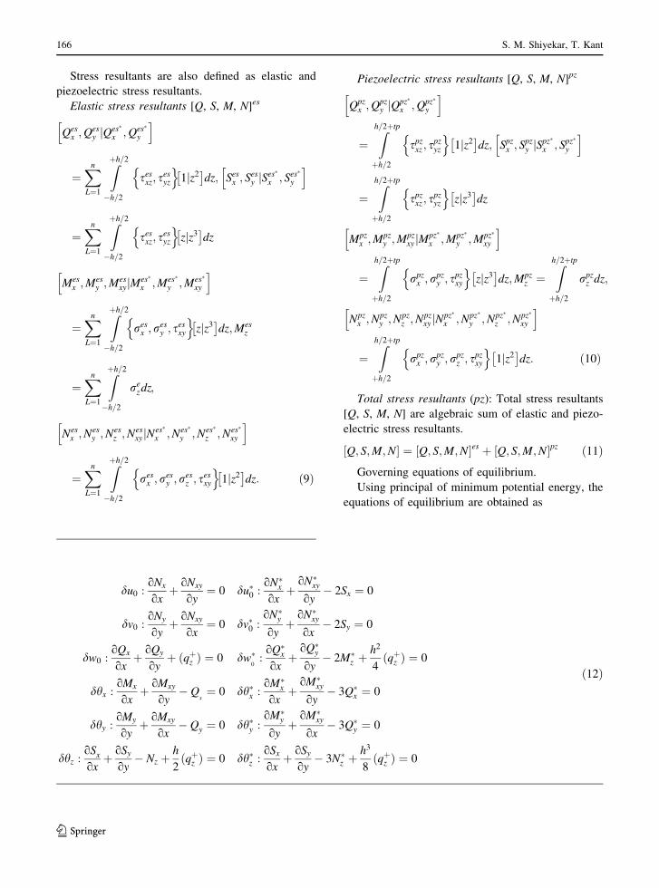
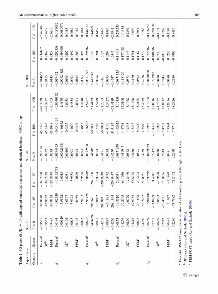
Table 1 FG plates (Eh/E0 = 0.1) with applied sinusoidal mechanical and electrical loadings | PFRC at top
Aspect ratio S = 10 S = 20 S = 100
Quantity Source V = 0 V = 100 V = -100 V = 0 V = 100 V = -100 V = 0 V = 100 V = -100
�w Presenta -8.6140 3164.12 -3181.35 -8.3577 790.3310 -807.046 -8.2750 23.7481 -40.2981
3Db -8.7397 3253.30 -3270.80 -8.5437 813.7105 -830.7979 -8.4806 23.9160 -40.5745
FEMc -8.6673 3212.90 -3230.30 -8.4154 797.9455 -814.7764 -8.3292 24.4974 -41.4587
�u Presenta -0.0905 -3.8486 3.6674 -0.0899 -1.14816 0.988288 -0.089722 -0.1336 -0.04584
0.1653 -112.9800 113.311 0.1689 -26.5921 26.9299 0.170091 -0.8807 1.22091
3Db -0.0914 -3.1845 3.0017 -0.0912 -0.9839 0.8015 -0.0912 -0.1285 -0.0539
0.1686 -114.0117 114.3489 0.1735 -27.0971 27.4441 0.175 -0.8991 1.2493
FEMc -0.0901 -3.0418 2.8616 -0.0902 -1.0641 0.8838 -0.0901 -0.1322 -0.0480
0.1714 -107.7880 108.1308 0.1716 -26.3653 26.7085 0.1715 -0.8840 1.2270
�rx Presenta 0.3908 -33.732 34.5138 0.3848 -7.74463 8.57438 0.38294 0.06279 0.703096
-0.0848 47.3070 -47.4767 -0.0846 11.26 -11.4293 -0.0845 0.3627 -0.53194
3Db 0.4042 -41.0915 41.8999 0.4031 -9.8557 10.6619 0.4027 -0.0061 0.8115
-0.0807 44.3075 -44.4689 -0.0796 10.6491 -10.8083 -0.0793 0.3451 -0.5036
FEMc 0.4066 -42.1225 42.9357 0.4068 -9.6579 10.4715 0.4066 0.0199 0.8013
-0.0793 43.0275 -43.1862 -0.0794 10.5905 -10.7493 -0.0793 0.3460 -0.5046
�ry Presenta 0.3763 -163.0770 163.83 0.3697 -41.0169 41.7565 0.36762 -1.29497 2.03021
-0.0866 30.8163 -30.9899 -0.0862 7.70831 -7.88081 -0.08611 0.22666 -0.398894
3Db 0.3900 -170.3199 171.0999 0.3883 -43.1562 43.9327 0.3877 -1.3654 2.1408
-0.0825 28.1032 -28.2681 -0.0812 7.1105 -7.2729 -0.0808 0.2088 -0.3704
FEMc 0.3916 -172.9020 173.6851 0.3913 -43.5671 44.3496 0.3909 -1.3748 2.1565
-0.0810 28.0609 -28.2229 -0.0810 7.0834 -7.2453 -0.0809 0.2072 -0.3689
�sxy Presenta -0.2116 55.3721 -55.7955 -0.20979 13.8615 -14.2811 -0.2091 0.356017 -0.77434
0.0408 -19.0577 19.1394 0.04162 -4.6504 4.7336 0.0418 -0.144775 0.228522
3Db -0.2138 56.9184 -57.3461 -0.2131 14.2724 -14.6986 -0.2128 0.3692 -0.7948
0.0416 -19.4500 19.5333 0.0427 -4.7790 4.8645 0.0431 -0.1491 0.2353
FEMc -0.2148 57.9332 -58.3627 -0.2148 14.3377 -14.7673 -0.2147 0.3667 -0.7962
0.0431 -19.1536 19.2399 0.0431 -4.7614 4.8477 0.0431 -0.1489 0.2352
a Present-HOSNT12 using linear variation of electrostatic potential through the thicknessb 3D-Exact (Ray and Sachade 2006a)c FEM-FOST based (Ray and Sachade 2006b)
168 S. M. Shiyekar, T. Kant
123
Ta
ble
2F
Gp
late
s(E
h/E
0=
10
)w
ith
app
lied
sin
uso
idal
mec
han
ical
and
elec
tric
allo
adin
gs
|P
FR
Cat
top
Asp
ect
rati
oS
=1
0S
=2
0S
=1
00
Qu
anti
tyS
ou
rce
V=
0V
=1
00
V=
-1
00
V=
0V
=1
00
V=
-1
00
V=
0V
=1
00
V=
-1
00
� wP
rese
nta
-0
.95
75
18
7.8
14
0-
18
9.7
29
0-
0.9
25
10
74
5.5
33
6-
47
.38
39
-0
.91
46
57
0.9
34
16
2-
2.7
63
48
3D
b-
0.9
55
31
86
.82
22
-1
88
.73
29
-0
.92
52
45
.53
93
-4
7.3
89
7-
0.9
15
50
.93
68
-2
.76
78
FE
Mc
-0
.94
85
18
3.9
17
8-
18
5.8
14
8-
0.9
23
34
5.2
93
8-
47
.14
03
-0
.91
45
0.9
32
8-
2.7
61
9
� uP
rese
nta
-0
.01
94
-0
.02
33
0-
0.0
15
57
78
-0
.01
94
65
3-
0.0
34
01
33
-0
.00
49
17
2-
0.0
19
47
2-
0.0
20
23
58
-0
.01
87
08
2
0.0
09
29
-5
.98
32
16
.00
18
0.0
09
25
98
1-
1.4
68
52
1.4
87
04
0.0
09
24
85
1-
0.0
49
60
06
0.0
68
09
76
3D
b-
0.0
19
4-
0.0
30
7-
0.0
08
1-
0.0
01
95
-0
.03
37
-0
.00
53
-0
.01
95
-0
.02
02
-0
.01
88
0.0
09
3-
5.9
37
35
.95
58
0.0
09
3-
1.4
67
01
.48
55
0.0
09
3-
0.0
49
70
.06
82
FE
Mc
-0
.01
95
0.0
45
9-
0.0
84
9-
0.0
19
5-
0.0
29
7-
0.0
09
3-
0.0
19
5-
0.0
20
2-
0.0
18
7
0.0
09
3-
5.9
40
25
.95
88
0.0
09
3-
1.4
65
51
.48
40
0.0
09
3-
0.0
49
60
.06
81
� r xP
rese
nta
0.0
87
3-
5.9
14
25
6.0
89
05
0.0
87
25
38
-1
.36
82
21
.54
27
30
.08
71
99
20
.02
95
86
70
.14
48
12
-0
.42
46
94
20
6.3
48
-2
07
.19
80
-0
.41
90
55
0.5
80
8-
51
.41
89
-0
.41
72
43
1.6
13
8-
2.4
48
29
3D
b0
.08
71
-5
.80
52
5.9
79
40
.08
73
-1
.37
42
1.5
48
90
.08
74
0.0
29
10
.14
57
-0
.42
01
20
3.9
84
-2
04
.82
49
-0
.41
71
50
.39
11
-5
1.2
25
3-
0.4
16
11
.61
24
-2
.44
46
FE
Mc
0.0
89
3-
6.1
98
56
.37
72
0.0
89
3-
1.4
17
01
.54
27
30
.08
93
0.0
29
90
.14
86
-0
.42
50
20
8.1
96
4-
20
9.0
44
7-
0.4
25
05
1.4
18
3-
51
.41
89
-0
.42
47
1.6
44
7-
2.4
94
1
� r yP
rese
nta
0.0
87
3-
19
.83
10
20
.00
51
0.0
87
16
59
-4
.92
92
55
.10
35
80
.08
71
12
5-
0.1
14
01
0.2
88
23
5
-0
.42
56
59
.25
43
-6
0.1
05
6-
0.4
19
94
51
4.4
70
1-
15
.31
00
-0
.41
81
29
0.1
77
08
8-
1.0
13
35
3D
b0
.08
70
-1
9.6
72
01
9.8
46
00
.08
72
-4
.93
33
5.1
07
80
.08
73
-0
.11
45
0.2
89
2
-0
.42
13
57
.97
52
-5
8.8
17
8-
0.4
18
01
4.3
33
8-
15
.16
98
-0
.41
70
0.1
75
1-
1.0
09
0
FE
Mc
0.0
89
3-
20
.16
38
20
.34
24
0.0
89
3-
5.0
40
05
.21
85
0.0
89
2-
0.1
16
70
.29
51
-0
.42
60
58
.24
32
-5
9.0
95
1-
0.4
25
91
4.5
56
0-
15
.40
79
-0
.42
56
0.1
77
2-
1.0
28
3
� s xy
Pre
sen
ta-
0.0
46
96
.90
20
8-
6.9
95
95
-0
.04
69
95
91
.69
83
-1
.79
23
1-
0.0
47
01
28
0.0
22
89
62
-0
.11
69
22
0.2
25
1-
71
.04
39
71
.49
41
0.2
24
22
3-
17
.43
32
17
.88
16
0.2
23
94
3-
0.4
80
29
60
.92
81
18
3
3D
b-
0.0
46
96
.85
93
-6
.95
30
-0
.04
70
1.6
98
2-
1.7
92
2-
0.0
47
00
.02
30
-0
.11
71
0.2
24
2-
70
.47
71
70
.92
56
0.2
24
3-
17
.42
32
17
.87
17
0.2
24
3-
0.4
81
30
.92
98
FE
Mc
-0
.04
81
7.1
02
7-
7.1
98
9-
0.0
48
11
.73
94
-1
.83
56
-0
.04
80
0.0
23
3-
0.1
19
4
0.2
29
0-
71
.78
82
72
.24
62
0.2
29
0-
17
.77
46
18
.23
26
0.2
28
9-
0.4
90
70
.94
86
aP
rese
nt-
HO
SN
T1
2u
sin
gli
nea
rv
aria
tio
no
fel
ectr
ost
atic
po
ten
tial
thro
ug
hth
eth
ick
nes
sb
3D
-Ex
act
(Ray
and
Sac
had
e2
00
6a)
cF
EM
-FO
ST
bas
ed(R
ayan
dS
ach
ade
20
06
b)
An electromechanical higher order model 169
123
Ta
ble
3F
Gp
late
s(E
h/E
0=
0.1
)w
ith
app
lied
sin
uso
idal
mec
han
ical
and
elec
tric
allo
adin
gs
|P
FR
Cat
bo
tto
m
Asp
ect
rati
oS
=1
0S
=2
0S
=1
00
Qu
anti
tyS
ou
rce
V=
0V
=1
00
V=
-1
00
V=
0V
=1
00
V=
-1
00
V=
0V
=1
00
V=
-1
00
� wP
rese
nta
-9
.19
78
71
77
6.2
1-
17
94
.6-
8.9
79
24
30
.70
5-
44
8.6
63
-8
.90
93
8.5
92
93
-2
6.4
11
5
3D
b-
9.2
74
81
74
8.2
-1
80
7.5
-9
.05
49
43
6.0
14
2-
45
4.1
24
0-
8.9
33
88
.75
87
-2
6.7
28
1
FE
Mc
-9
.27
61
17
89
.0-
17
66
.7-
9.0
23
34
30
.46
78
-4
48
.51
45
-8
.93
64
8.6
32
3-
26
.50
51
� uP
rese
nta
-0
.08
77
37
85
7.1
54
5-
57
.33
00
-0
.08
73
52
41
4.0
39
3-
14
.21
40
-0
.08
72
25
30
.47
54
72
-0
.64
99
22
0.1
87
77
60
.78
28
43
-0
.40
72
92
0.1
91
34
0.4
70
68
7-
0.0
88
00
69
0.1
92
52
30
.20
53
44
0.1
79
70
8
3D
b-
0.0
89
05
7.1
02
0-
57
.28
01
-0
.08
86
14
.11
24
-1
4.2
89
6-
0.0
88
50
.47
83
-0
.65
52
0.1
89
00
.52
88
-0
.15
07
0.1
92
50
.38
82
-0
.00
32
0.1
93
60
.20
29
0.1
84
4
FE
Mc
-0
.08
77
57
.10
20
-5
7.0
79
2-
0.0
87
81
4.0
43
1-
14
.21
86
-0
.08
77
0.4
76
0-
0.6
51
4
0.1
93
1-
0.0
20
10
.40
63
0.1
93
20
.39
63
-0
.01
00
0.1
93
00
.20
46
0.1
81
5
� rx
Pre
sen
ta0
.41
22
44
-2
00
.26
62
01
.09
10
.41
00
56
-4
9.1
31
74
9.9
51
90
.40
93
51
-1
.56
43
2.3
83
0
-0
.08
69
93
15
.11
51
1-
5.2
89
09
-0
.08
53
27
61
.17
39
6-
1.3
44
62
-0
.08
48
17
4-
0.0
34
94
71
-0
.13
46
88
3D
b0
.40
32
-1
95
.93
56
19
6.7
41
90
.40
11
-4
8.4
12
74
9.2
15
00
.40
05
-1
.54
86
2.3
49
5
-0
.08
82
5.4
97
7-
5.6
75
3-
0.0
87
11
.29
84
-1
.47
26
-0
.08
66
-0
.03
13
-0
.14
19
FE
Mc
0.4
06
0-
19
8.9
89
41
99
.80
15
0.4
06
1-
49
.15
87
49
.97
08
0.4
05
8-
1.5
72
92
.38
44
-0
.08
82
5.7
88
3-
5.9
64
7-
0.0
88
21
.31
81
-1
.49
45
-0
.08
81
-0
.03
28
-0
.14
35
�ry
Pre
sen
ta0
.42
09
11
-5
8.3
82
65
9.2
24
40
.41
85
02
-1
4.2
69
01
5.1
06
00
.41
77
29
-0
.16
97
09
1.0
05
17
-0
.08
61
72
18
.54
07
-1
8.7
13
0-
0.0
84
49
84
.61
23
3-
4.7
81
32
-0
.08
39
81
80
.10
44
39
-0
.27
24
03
3D
b0
.41
15
-5
4.9
28
65
5.7
51
50
.40
93
-1
3.5
76
91
4.3
95
40
.40
85
-0
.15
29
0.9
70
0
-0
.08
80
18
.88
95
-1
9.0
65
5-
0.0
86
34
.73
69
-4
.90
96
-0
.08
58
0.1
08
2-
0.2
79
8
FE
Mc
0.4
14
8-
54
.29
76
55
.12
72
0.4
14
7-
13
.56
90
14
.39
84
0.4
14
3-
0.1
48
40
.97
71
-0
.08
74
19
.26
64
-1
9.4
41
2-
0.0
87
44
.81
61
-4
.99
09
-0
.08
73
0.1
09
6-
0.2
84
2
� s xy
Pre
sen
ta-
0.2
16
36
16
7.1
78
5-
67
.61
12
-0
.21
53
19
16
.49
60
-1
6.9
26
6-
0.2
14
97
80
.45
17
34
-0
.88
16
9
0.0
44
96
75
-6
.52
36
36
.61
35
60
.04
58
24
6-
1.6
05
44
1.6
97
06
0.0
46
10
82
-0
.02
00
69
40
.11
22
86
3D
b-
0.2
19
36
7.4
89
8-
67
.92
85
-0
.21
82
16
.68
63
-1
7.1
22
7-
0.2
17
80
.45
81
-0
.89
37
0.0
45
3-
6.5
68
16
.65
87
0.0
46
1-
1.6
25
51
.71
77
0.0
46
4-
0.0
20
70
.11
35
FE
Mc
-0
.22
08
68
.23
17
-6
8.6
73
4-
0.2
20
91
6.8
96
6-
17
.33
83
-0
.22
08
0.4
63
5-
0.9
05
1
0.0
47
2-
6.7
49
16
.84
36
0.0
47
2-
1.6
52
11
.74
66
0.0
47
2-
0.0
20
70
.11
51
aP
rese
nt-
HO
SN
T1
2u
sin
gli
nea
rv
aria
tio
no
fel
ectr
ost
atic
po
ten
tial
thro
ug
hth
eth
ick
nes
sb
3D
-Ex
act
(Ray
and
Sac
had
e2
00
6a)
cF
EM
-FO
ST
bas
ed(R
ayan
dS
ach
ade
20
06
b)
170 S. M. Shiyekar, T. Kant
123
Ta
ble
4F
Gp
late
s(E
h/E
0=
10
)w
ith
app
lied
sin
uso
idal
mec
han
ical
and
elec
tric
allo
adin
gs
|P
FR
Cat
bo
tto
m
Asp
ect
rati
oS
=1
0S
=2
0S
=1
00
Qu
anti
tyS
ou
rce
V=
0V
=1
00
V=
-1
00
V=
0V
=1
00
V=
-1
00
V=
0V
=1
00
V=
-1
00
� wP
rese
nta
-0
.94
72
26
35
9.1
41
-3
61
.04
-0
.91
71
96
89
.24
63
-9
1.0
80
7-
0.9
06
72
52
.70
14
9-
4.5
14
94
3D
b-
0.9
42
83
59
.08
74
-3
60
.99
38
-0
.91
64
89
.54
68
-9
1.3
87
7-
0.9
07
62
.71
47
-4
.53
46
FE
Mc
-0
.94
16
36
0.3
10
8-
36
2.1
94
0-
0.9
20
58
9.4
06
4-
91
.23
92
-0
.91
00
2.7
02
8-
4.5
18
0
� uP
rese
nta
-0
.01
90
67
51
2.6
57
7-
12
.69
60
-0
.01
91
92
42
.95
97
6-
2.9
98
15
-0
.01
92
02
40
.09
74
82
7-
0.1
35
88
8
0.0
09
31
94
60
.26
88
49
-0
.25
02
13
0.0
09
28
04
50
.08
60
99
-0
.06
75
38
10
.00
92
68
73
0.0
12
50
03
0.0
06
03
71
8
3D
b-
0.0
19
21
2.4
66
4-
12
.50
49
-0
.01
93
2.9
55
7-
2.9
94
2-
0.0
19
30
.09
78
-0
.13
64
0.0
09
30
.25
78
-0
.23
91
0.0
09
30
.08
35
-0
.06
49
0.0
09
30
.01
24
0.0
06
2
FE
Mc
-0
.01
93
11
.92
37
-1
1.9
62
2-
0.0
19
32
.91
47
-2
.95
32
-0
.01
92
0.0
97
4-
0.1
35
9
0.0
09
30
.19
67
-0
.17
81
0.0
09
30
.08
11
-0
.06
25
0.0
09
30
.01
25
0.0
06
1
� rx
Pre
sen
ta0
.08
74
02
8-
50
.26
09
50
.43
64
0.0
87
67
86
-1
1.8
39
71
2.0
15
0.0
87
64
65
-0
.38
08
49
0.5
56
14
2
-0
.42
01
62
47
.79
41
-4
8.6
35
1-
0.4
14
70
71
1.1
66
6-
11
.99
61
-0
.41
28
57
0.0
44
05
07
-0
.56
97
64
3D
b0
.08
65
-4
8.6
23
34
8.7
96
30
.08
66
-1
1.6
55
91
1.8
29
10
.08
66
-0
.37
75
0.5
50
7
-0
.42
28
47
.62
47
-4
8.4
70
3-
0.4
17
91
1.4
49
1-
12
.28
48
-0
.41
63
0.0
56
40
-0
.88
90
FE
Mc
0.0
88
3-
47
.84
63
48
.02
30
0.0
88
3-
11
.76
81
11
.94
48
0.0
88
3-
0.3
84
20
.56
08
-0
.42
50
50
.81
26
-5
1.6
62
6-
0.4
25
01
1.7
70
4-
12
.62
04
-0
.42
46
0.0
54
6-
0.9
03
9
� ry
Pre
sen
ta0
.08
77
43
3-
32
.44
60
32
.62
20
0.0
87
86
32
-8
.04
25
28
.21
82
50
.08
78
22
3-
0.2
37
32
0.4
12
96
4
-0
.41
75
12
18
6.4
51
-1
87
.28
9-
0.4
12
98
74
6.6
48
9-
47
.47
69
-0
.41
11
22
1.4
75
66
-2
.29
79
3D
b0
.08
67
-3
1.3
03
03
1.4
76
30
.08
68
-7
.88
72
8.0
60
70
.08
68
-0
.23
38
0.4
07
4
-0
.42
12
18
5.7
53
1-
18
6.5
95
5-
0.4
16
24
6.9
15
1-
47
.74
76
-0
.41
46
1.4
88
9-
2.3
18
1
FE
Mc
0.0
88
5-
31
.87
07
32
.04
78
0.0
88
5-
8.0
31
48
.20
85
0.0
88
5-
0.2
37
80
.41
47
-0
.42
33
19
0.3
62
0-
19
1.2
08
6-
0.4
23
24
7.8
96
7-
48
.74
31
-0
.42
29
1.5
16
8-
2.3
62
6
� s xy
Pre
sen
ta-
0.0
46
24
92
1.2
81
3-
21
.77
41
-0
.04
64
72
85
.25
40
3-
5.3
46
98
-0
.04
64
92
70
.16
38
13
-0
.25
67
98
0.2
23
89
-6
2.8
31
46
3.2
80
10
.22
34
12
-1
5.6
60
51
6.1
07
30
.22
31
22
-0
.41
37
20
.85
99
63
3D
b-
0.0
46
62
1.4
66
2-
21
.55
94
-0
.04
67
5.2
58
3-
5.3
51
6-
0.0
46
70
.16
46
-0
.25
79
0.2
24
9-
62
.83
48
63
.28
47
0.2
24
0-
15
.71
40
16
.16
20
0.2
23
7-
0.4
16
10
.86
34
FE
Mc
-0
.04
76
21
.47
43
-2
1.5
69
5-
0.0
47
65
.33
30
-5
.42
82
-0
.04
76
0.1
67
4-
0.2
62
6
0.2
28
26
4.9
66
26
5.4
22
60
.22
82
-1
6.0
69
91
6.5
26
40
.22
82
-0
.42
28
0.8
79
1
aP
rese
nt-
HO
SN
T1
2u
sin
gli
nea
rv
aria
tio
no
fel
ectr
ost
atic
po
ten
tial
thro
ug
hth
eth
ick
nes
sb
3D
-Ex
act
(Ray
and
Sac
had
e2
00
6a)
cF
EM
-FO
ST
bas
ed(R
ayan
dS
ach
ade
20
06
b)
An electromechanical higher order model 171
123
displacement, in-plane normal stresses and transverse
shear stress are evaluated and their comparison with
exact and FEM solutions are presented in Tables and
Figures.
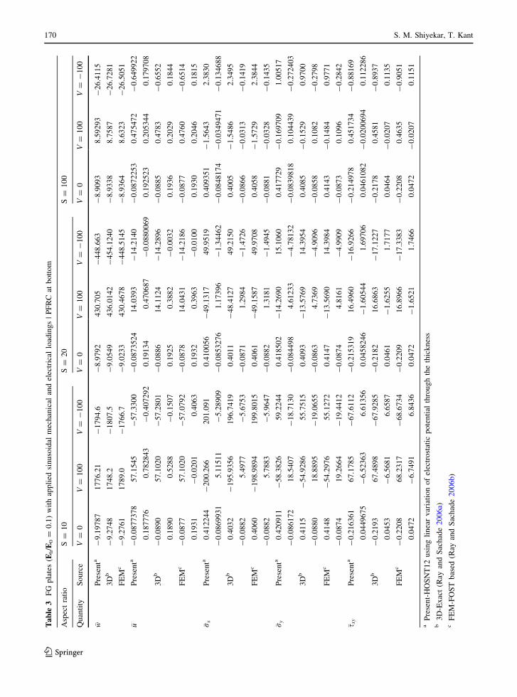
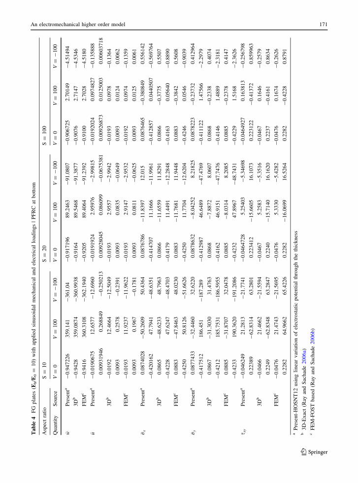
Tables 1, 2, 3, and 4 show comparison of numer-
ical results of for the cases I, II, III and IV,
respectively.
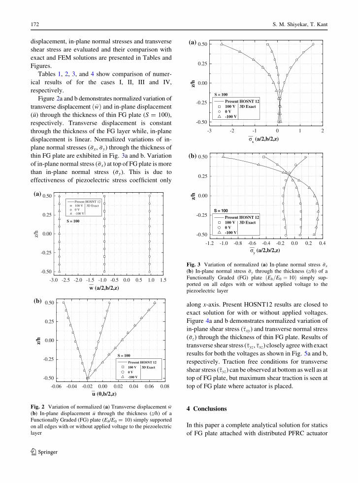
Figure 2a and b demonstrates normalized variation of
transverse displacement ð�wÞ and in-plane displacement
(�u) through the thickness of thin FG plate (S = 100),
respectively. Transverse displacement is constant
through the thickness of the FG layer while, in-plane
displacement is linear. Normalized variations of in-
plane normal stresses (�rx, �ry) through the thickness of
thin FG plate are exhibited in Fig. 3a and b. Variation
of in-plane normal stress (�rx) at top of FG plate is more
than in-plane normal stress (�ry). This is due to
effectiveness of piezoelectric stress coefficient only
along x-axis. Present HOSNT12 results are closed to
exact solution for with or without applied voltages.
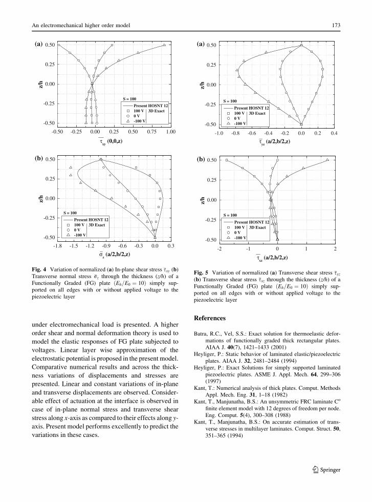
Figure 4a and b demonstrates normalized variation of
in-plane shear stress (�sxy) and transverse normal stress
(�rz) through the thickness of thin FG plate. Results of
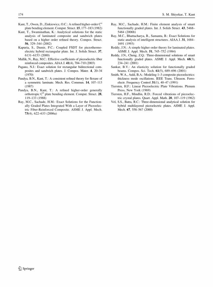
transverse shear stress (�syz,�sxz) closely agree with exact
results for both the voltages as shown in Fig. 5a and b,
respectively. Traction free conditions for transverse
shear stress (�syz) can be observed at bottom as well as at
top of FG plate, but maximum shear traction is seen at
top of FG plate where actuator is placed.
4 Conclusions
In this paper a complete analytical solution for statics
of FG plate attached with distributed PFRC actuator
-0.50
-0.25
0.00
0.25
0.50
z/h
w (a/2,b/2,z)
Present HOSNT 12 100 V 3D Exact 0 V -100 V
S = 100
(a)
-3.0 -2.5 -2.0 -1.5 -1.0 -0.5 0.0 0.5 1.0 1.5
-0.06 -0.04 -0.02 0.00 0.02 0.04 0.06 0.08
-0.50
-0.25
0.00
0.25
0.50
z/h
u (0,b/2,z)
Present HOSNT 12 100 V 3D Exact 0 V -100 V
S = 100
(b)
Fig. 2 Variation of normalized (a) Transverse displacement �w(b) In-plane displacement �u through the thickness (z/h) of a
Functionally Graded (FG) plate (Eh/E0 = 10) simply supported
on all edges with or without applied voltage to the piezoelectric
layer
-0.50
-0.25
0.00
0.25
0.50
S = 100
z/h
σx (a/2,b/2,z)
Present HOSNT 12 100 V 3D Exact 0 V -100 V
(a)
(b)
-3 -2 -1 0 1 2
-1.2 -1.0 -0.8 -0.6 -0.4 -0.2 0.0 0.2 0.4
-0.50
-0.25
0.00
0.25
0.50
z/h
σy (a/2,b/2,z)
Present HOSNT 12 100 V 3D Exact 0 V -100 V
S = 100
Fig. 3 Variation of normalized (a) In-plane normal stress �rx
(b) In-plane normal stress �ry through the thickness (z/h) of a
Functionally Graded (FG) plate ðEh=E0 ¼ 10Þ simply sup-
ported on all edges with or without applied voltage to the
piezoelectric layer
172 S. M. Shiyekar, T. Kant
123
under electromechanical load is presented. A higher
order shear and normal deformation theory is used to
model the elastic responses of FG plate subjected to
voltages. Linear layer wise approximation of the
electrostatic potential is proposed in the present model.
Comparative numerical results and across the thick-
ness variations of displacements and stresses are
presented. Linear and constant variations of in-plane
and transverse displacements are observed. Consider-
able effect of actuation at the interface is observed in
case of in-plane normal stress and transverse shear
stress along x-axis as compared to their effects along y-
axis. Present model performs excellently to predict the
variations in these cases.
References
Batra, R.C., Vel, S.S.: Exact solution for thermoelastic defor-
mations of functionally graded thick rectangular plates.
AIAA J. 40(7), 1421–1433 (2001)
Heyliger, P.: Static behavior of laminated elastic/piezoelectric
plates. AIAA J. 32, 2481–2484 (1994)
Heyliger, P.: Exact Solutions for simply supported laminated
piezoelectric plates. ASME J. Appl. Mech. 64, 299–306
(1997)
Kant, T.: Numerical analysis of thick plates. Comput. Methods
Appl. Mech. Eng. 31, 1–18 (1982)
Kant, T., Manjunatha, B.S.: An unsymmetric FRC laminate Co
finite element model with 12 degrees of freedom per node.
Eng. Comput. 5(4), 300–308 (1988)
Kant, T., Manjunatha, B.S.: On accurate estimation of trans-
verse stresses in multilayer laminates. Comput. Struct. 50,
351–365 (1994)
-0.50
-0.25
0.00
0.25
0.50z/
h
τxy
(0,0,z)
Present HOSNT 12 100 V 3D Exact 0 V -100 V
S = 100
(a)
(b)
-0.50 -0.25 0.00 0.25 0.50 0.75 1.00
-1.8 -1.5 -1.2 -0.9 -0.6 -0.3 0.0 0.3
-0.50
-0.25
0.00
0.25
0.50
z/h
σz (a/2,b/2,z)
Present HOSNT 12 100 V 3D Exact 0 V -100 V
S = 100
Fig. 4 Variation of normalized (a) In-plane shear stress �sxy (b)
Transverse normal stress �rz through the thickness (z/h) of a
Functionally Graded (FG) plate ðEh=E0 ¼ 10Þ simply sup-
ported on all edges with or without applied voltage to the
piezoelectric layer
(b)
(a)
-1.0 -0.8 -0.6 -0.4 -0.2 0.0 0.2 0.4
-0.50
-0.25
0.00
0.25
0.50
z/h
τyz
(a/2,b/2,z)
Present HOSNT 12 100 V 3D Exact 0 V -100 V
S = 100
-2 -1 0 1 2
-0.50
-0.25
0.00
0.25
0.50
z/h
τxz
(a/2,b/2,z)
Present HOSNT 12 100 V 3D Exact 0 V -100 V
S = 100
Fig. 5 Variation of normalized (a) Transverse shear stress �syz
(b) Transverse shear stress �sxz through the thickness (z/h) of a
Functionally Graded (FG) plate ðEh=E0 ¼ 10Þ simply sup-
ported on all edges with or without applied voltage to the
piezoelectric layer
An electromechanical higher order model 173
123
Kant, T., Owen, D., Zinkiewicz, O.C.: A refined higher-order Co
plate bending element. Comput. Struct. 15, 177–183 (1982)
Kant, T., Swaminathan, K.: Analytical solutions for the static
analysis of laminated composite and sandwich plates
based on a higher order refined theory. Compos. Struct.
56, 329–344 (2002)
Kapuria, S., Dumir, P.C.: Coupled FSDT for piezothermo-
electric hybrid rectangular plate. Int. J. Solids Struct. 37,
6131–6153 (2000)
Mallik, N., Ray, M.C.: Effective coefficients of piezoelectric fiber
reinforced composites. AIAA J. 41(4), 704–710 (2003)
Pagano, N.J.: Exact solution for rectangular bidirectional com-
posites and sandwich plates. J. Compos. Mater. 4, 20–34
(1970)
Pandya, B.N., Kant, T.: A consistent refined theory for flexure of
a symmetric laminate. Mech. Res. Commun. 14, 107–113
(1987)
Pandya, B.N., Kant, T.: A refined higher-order generally
orthotropic C0 plate bending element. Comput. Struct. 28,
119–133 (1988)
Ray, M.C., Sachade, H.M.: Exact Solutions for the Function-
ally Graded Plates Integrated With a Layer of Piezoelec-
tric Fiber-Reinforced Composite. ASME J. Appl. Mech.
73(4), 622–633 (2006a)
Ray, M.C., Sachade, H.M.: Finite element analysis of smart
functionally graded plates. Int. J. Solids Struct. 43, 5468–
5484 (2006b)
Ray, M.C., Bhattacharya, R., Samanta, B.: Exact Solutions for
static analysis of intelligent structures. AIAA J. 31, 1684–
1691 (1993)
Reddy, J.N.: A simple higher order theory for laminated plates.
ASME J. Appl. Mech. 51, 745–752 (1984)
Reddy, J.N., Cheng, Z.Q.: Three-dimensional solutions of smart
functionally graded plates. ASME J. Appl. Mech. 68(3),
234–241 (2001)
Sankar, B.V.: An elasticity solution for functionally graded
beams. Compos. Sci. Tech. 61(5), 689–696 (2001)
Smith, W.A., Auld, B.A.: Modeling 1–3 composite piezoelectrics:
thickness mode oscillations. IEEE Trans. Ultrason. Ferro-
electr. Frequency Control 31(1), 40–47 (1991)
Tiersten, H.F.: Linear Piezoelectric Plate Vibrations. Plenum
Press, New York (1969)
Tiersten, H.F., Mindlin, R.D.: Forced vibrations of piezoelec-
tric crystal plates. Quart. Appl. Math. 20, 107–119 (1962)
Vel, S.S., Batra, R.C.: Three-dimensional analytical solution for
hybrid multilayered piezoelectric plates. ASME J. Appl.
Mech. 67, 558–567 (2000)
174 S. M. Shiyekar, T. Kant
123


![Free vibration of higher-order sandwich and composite ...tkant/papers/TKant-IITB-JP115.pdf · Bhashyam and Prathap [4] detected the second spectrum of frequencies, known as shear](https://img.pdfslide.us/doc/110x75/5e92d65352e8136d4b782412/free-vibration-of-higher-order-sandwich-and-composite-tkantpaperstkant-iitb-jp115pdf.jpg)