Embed Size (px)
Citation preview
International Journal of Engineering and Manufacturing Science.
ISSN 2249-3115 Volume 7, Number 2 (2017), pp. 309-318
© Research India Publications
http://www.ripublication.com
Investigation Into Flow Field of Centrifugal Pump
Impeller
B.Subbarao 1, Dr. E.Ramjee 2, Dr. M. Devaiah3, Dr. T. Siva Prasad4
1, 3, 4 Department of Mechanical Engineering, Geethanjali College of Engineering and
Technology, Telangana State, India
2Professor, Department of Mechanical Engineering, JNTU Hyderabad, Telangana,
India.
Abstract
This study deals with the design and performance analysis of centrifugal pump
impeller. In this thesis, centrifugal pump is analyzed by using a single-stage end
suction centrifugal pump. Two main components of a centrifugal pump are the
impeller and the casing. The impeller is a rotating component and the casing is a
stationary component. In centrifugal pump, water exits radially, while water
enters axially through the impeller eyes. The pump casing is to guide the liquid to
the impeller, converts the high velocity kinetic energy of the flow from the
impeller discharge into pressure. A mean of centrifugal pump impeller is passed
out and analyzed to get the best performance point. The design and performance
analysis of centrifugal pump impeller are chosen because pump is the most useful
mechanical Rotodynamic machine in fluid works which is widely used in
domestic, irrigation, industry, large plants and river water pumping system. In
this study, the pump is driven by 5.5 KW electric motor and the design is done in
CFturbo 9 modeling package. The head and flow rate of this pump are 19.50 m
and 20 LPS respectively and the motor speed is 2900 rpm. The number of
impeller blade is 6 blades. The performance study of centrifugal pump is carried
out after designing the dimensions of centrifugal pump. Simulation of present
work is carried out in a commercial CFD software ANSYS fluent 14.5.
Corresponding pressure contours and velocity contours are plotted at design flow
rate (20 LPS), part flow rate (16 LPS) and excess flow rate (25 LPS). The
simulation values are compared with analytical solution
Key Words: CFD and ANSYS fluent 14.5.
310 B.Subbarao, Dr. E.Ramjee, Dr. M. Devaiah and Dr. T. Siva Prasad
1. INTRODUCTION
1.1 Geometry Modeling & Simulation:
In design of a pump 3 variables are to be considered. They’re:
1. Head developed by the pump
2. Discharge/ Flow at the particular head
3. Speed of the Pump
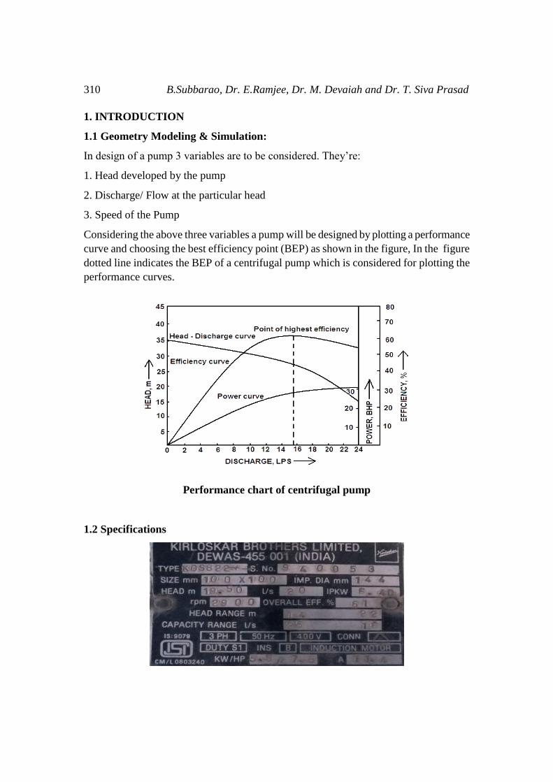
Considering the above three variables a pump will be designed by plotting a performance
curve and choosing the best efficiency point (BEP) as shown in the figure, In the figure
dotted line indicates the BEP of a centrifugal pump which is considered for plotting the
performance curves.
Performance chart of centrifugal pump
1.2 Specifications
Investigation Into Flow Field of Centrifugal Pump Impeller 311
1.3 Pressure Calculations
Case – 1
Mass flow rate 20 LPS = 20 kg/s = 72m3/hr
Head developed = 19.50 m
Delivery head (hd) = 19.50m = 1.9118 bar
Suction Head (hs) = 15.257m = 1.495 bar
Static Head (Hs) = hs + hd
= 3.410 bar
= 34,000 Pascal
Manometric head (Hm) = hs + hd + hf + 𝑉𝑑22𝑔
hf = 0.8m = 0.0784 bar
Vd = 2.5465 m/s
∴Hm = 3.410 + 0.0784 + 0.3305
= 3.889 bar
= 381,890 Pascal
Case - 2
Mass flow rate 25LPS = 25 kg/s = 90 m3/hr
Head developed = 14 m
Delivery head (hd) = 14 m = 1.3725 bar
Suction head (hs) = 15.257 m = 1.4958 bar
Static Head (Hs) = hs + hd
= 1.4958 + 1.3725
= 2.8683 bar
= 286,830 Pascal
Manometric Head (Hm) = Hs + hf + 𝑉𝑑22𝑔
hf = 1.1m = 0.1078 bar
Vd = 3.1831 m/s
Hm = 2.8683 + 0.1078 + 0.5164
= 3.4925 bar = 349,250 Pascal

312 B.Subbarao, Dr. E.Ramjee, Dr. M. Devaiah and Dr. T. Siva Prasad
Case - 3
Mass flow rate 16 LPS = 16 kg/s = 57.6m3/hr
Head developed = 33 m
Delivery head (h0) = 33m = 3.2353 bar
Suction head (hs) = 15.257 m = 1.4958 bar
Static head (Hs) = hs + hd
= 1.4958 + 3.2353
= 4.7311 bar
= 473,109.99 Pascal
Manometric head (Hm) = Hs + hf + 𝑉𝑑22𝑔
hf = 0.4487 m = 0.0439 bar
Vd = 2.0371 m/s
∴ Hm = 4.7311 + 0.0439 + 0.2115
= 4.9865 bar
= 498,650 Pascal
1.3 Analytical Results
S.
No Dimension Variable Notation Value
1 Mass flow rate Q 20 kg/s
2 Head H 19.50 m
3 Speed N 2900 RPM
4 Impeller inlet diameter D1 77.26 mm
5 Outlet diameter D2 144 mm
6 No. of blades Z 6
7 Vane/blade thickness t 5 mm
8 Inlet blade angle β1 30.15°
9 Outlet blade angle β2 43.77°
Investigation Into Flow Field of Centrifugal Pump Impeller 313
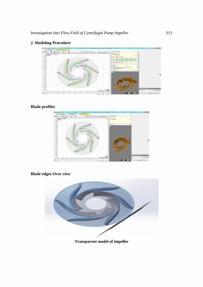
2. Modeling Procedure
Blade profiles
Blade edges-Over view
Transparent model of impeller

314 B.Subbarao, Dr. E.Ramjee, Dr. M. Devaiah and Dr. T. Siva Prasad
2.1 Geometry Analysis
CFD Analysis
Meshing of Impeller
Inflation at blade walls
2.2 Physical properties of fluids used in CFD
Materials Water Aluminum
Density kg/m3 998.3 2719
Specific Heat J/kg K 4.18 871
Thermal conductivity W/m k - 202.4
Viscosity Kg/ms 0.001003 -

Investigation Into Flow Field of Centrifugal Pump Impeller 315
3. RESULTS and Error Analysis
3.1Flowrate of 16 LPS
Velocity distribution at Inlet for 16 LPS flow rate
Pressure distribution on blades for 16 LPS flow rate
3.2 Flow rate of 20 LPS
Velocity distribution at Inlet for 20 LPS flow rate

316 B.Subbarao, Dr. E.Ramjee, Dr. M. Devaiah and Dr. T. Siva Prasad
Pressure distribution on blade for 20 LPS flow rate
3.3Flowrate of 25 LPS
Velocity distribution at Inlet for 25 LPS flow rate
Pressure distribution on blades for 25 LPS flow rate
3.4 Error Analysis
Analytical and Simulation results
For 16 LPS flow rate the Velocity value of simulation result is less when compared to
analytical result and the error is 15.285%.
The pressure value of simulation result is more when compared to the analytical result

Investigation Into Flow Field of Centrifugal Pump Impeller 317
and the error is 30.92%.
analytical result and the error is 2.69%.
The pressure value of simulation result is more when compared to the analytical result
and the error is 36.73%.
LPS flow rate the Velocity value of simulation result is more when compared to
analytical result and the error is 2.40%.
Flow Rate Velocity (m/s) Pressure (Pascal)
Analytical
Result
Simulation
Result
Error (%) Analytical
Result
Simulation
Result
Error
(%)
16 LPS 21.865 18.522 15.285 498650 721872 30.92
20 LPS 21.865 21.270 2.69 381890 603600 36.73
25 LPS 21.865 22.404 2.40 349250 566065 38.30
The pressure value of simulation result is more when compared to the analytical result
and the error is 38.30%.
4. CONCLUSIONS
From analytical solution it is observed that the efficiency increases till the BEP and
decreases as the flowrate increases. The head curve decreases with increase in flowrate.
The output power or hydraulic power also decreases as the flowrate increases. From
ANSYS simulation, the flow field distribution throughout the impeller is also observed.
At the inlet the velocity and pressure distribution is uniform at observed flowrates.
Similarly for the outlet velocity and pressure distribution drastic variations are observed.
On blades cavitation is observed at the trailing edge. Drastic changes in pressure and
velocity is observed at the outlet which is caused due to the cavitation at the tip of the
blade trailing edge. The same pattern of variation in pressure and velocity is observed at
designed flowrate (20 LPS), part flowrate (16LPS) and excess flowrate (25 LPS).
From the ANSYS simulation, it is observed that the simulation value of pressure rise is
more when compared to the analytical value (30.9% error) and the value of velocity in
the ANSYS simulation is lesser than the value obtained in analytical solution (2.4%
error). This is because of the flow reversal zone which is caused due to the vortices or
wakes at the tip of the blade. As there is a vortices formation, it causes drastic increase in
pressure at the localized region and due to the turbulence or flow reversal the magnitude
of velocity after the turbulent region decreases due to loss of energy in vortices
318 B.Subbarao, Dr. E.Ramjee, Dr. M. Devaiah and Dr. T. Siva Prasad
REFERENCES
[1] Eric Dick, Jan Vierendeels, Sven Serbruyns and John Vande Voorde, (2001)
“Performance prediction of centrifugal pumps with CFD tools”. Task quarterly 5
No 4 (2001), 579–594, tq0405e7/580 26 I 2002 BOP s.c., Retrieved from
http://www.bop.com.pl.
[2] Jose´ Gonza´lez, Joaquı´n Ferna´ndez, Eduardo Blanco, Carlos Santolaria(2002)
“Numerical Simulation of the Dynamic Effects Due to Impeller-Volute
Interaction in a Centrifugal Pump”. Vol. 124, JUNE 2002 Copyright © 2002 by
ASME Transactions of the ASME.
[3] Weidong Zhou, Zhimei Zhao, T. S. Lee, and S. H.Winoto (2003) “Investigation
of Flow through Centrifugal Pump Impellers Using Computational Fluid
Dynamics”. International Journal of Rotating Machinery, 9(1): 49–61, 2003
Copyright °c 2003 Taylor & Francis 1023-621X/03 $12.00 + .00 DOI:
10.1080/10236210390147380.
[4] K M Guleren and A Pinarbasi (2004) “Numerical simulation of the stalled flow
within a vaned centrifugal pump”. Proc. Instn Mech. Engrs Vol. 218 Part C: J.
Mechanical Engineering Science.
[5] Miguel Asuajea, Farid Bakira, SmaÏne Kouidri‡a, Robert Reya (2004) “Inverse
Design Method for Centrifugal Impellers and Comparison with Numerical
Simulation Tools”. International Journal of Computational Fluid Dynamics, 18:
2, 101 — 110.
[6] John S. Anagnostopoulos (2006) “CFD Analysis and Design Effects in a Radial
Pump Impeller”.Wseas Transactions on fluid mechanics. Issue 7, Vol. 1, July
2006 ISSN: 1790-5087.56
[7] José González, Carlos Santolaria (2006) “Unsteady Flow Structure and Global
Variables in a Centrifugal Pump”.Journal of Fluids Engineering Copyright ©
2006 by ASME September 2006, Vol. 128 / 937
[8] Si Huanga, Mohammed F. Islamb, Pengfei Liu (2006) “Numerical simulation of
3D turbulent flow through an entire stage in a multistage centrifugal pump”.
International Journal of Computational Fluid Dynamics, 20: 5,309 — 314.
[9] Adnan Ozturk, Kadir Aydin, Besir Sahin and Ali Pinarbasi (2009) “Effect of
impeller-diffuser radial gap ratio in a centrifugal pump”. Journal of Scientific &
Industrial Research Vol. 68, March 2009, pp.203-213.