Embed Size (px)
Citation preview
International Academic
Journal of
Science
and
Engineering International Academic Journal of Science and Engineering
Vol. 5, No. 2, 2018, pp. 42-62.
ISSN 2454-3896
42
www.iaiest.com
International Academic Institute for Science and Technology
Investigating the effect of dimensions and distance of micro
piles on the bearing capacity in a foundation settlement in
gravel soils
Mehdi Ahmadi a, Ahad Bagherzadeh Khalkhali
b, Hayl Radan
c, Behzad Dalili
d
a Master's degree in Civil Engineering-Geotechnics, Azad University, Electronic Unit. (corresponding author).
b Faculty Member, Islamic Azad University, Science and Research Branch, Civil Engineering Department, Tehran, Iran.
c Master's degree in Civil Engineering-Geotechnics, Azad University, Electronic Unit.
d Master's degree in Civil Engineering-Geotechnics, Azad University, Electronic Unit.
Abstract
The piles are members of steel, concrete, reinforced concrete and wood, which is used to build a deep
pile, if the landing capacity is not suitable for use. In spite of high costs, there are many cases in which
there are numerous cases of pile sticks used to protect the building against sewage and other factors. The
load on the pile is tolerated in two ways by the pile, part of which is tolerated by the side-pile resistance
and the other part by the reciprocating tip of the pile. This composite system is called a piled raft system,
or a piled raft foundation. In this research, Plaxis finite element software has been used to investigate the
capacity of microfractory bearing. The results of this modeling show that the maximum displacement is
about 3 mm, which occurred at the final modeling stage. In the first stage, the modeling of the level of
displacement is very small, due to the grain size of the soil and the dry assumption of the material. In the
second stage, the spatial variations show a sudden increase, due to the presence of pile s and the weight of
the pile holder. In the third stage, the soil is completely compressed so that the forces have no significant
effect on the summation, and the rate of the second stage and the third settlement are not significantly
different.
Keywords: Micro fractures, Bearing Capacity, settlement, Plaxis
International Academic Journal of Science and Engineering,
Vol. 5, No. 2, pp. 42-62.
43
Introduction
The piles are members of steel, concrete, reinforced concrete and wood, which is used to build a deep
pile, if the landing capacity is not suitable for use. In spite of high costs, there are many cases in which
there are numerous cases of pile used to protect the building against sewage and other factors. This
compound system is called a piled raft system, or a pile-base, in short. Pile-Raft system bases are
economically feasible because, when raft alone does not provide the required design in terms of cargo and
storage, using multiple pillars under the raft, the amount of load capacity is increased and the overall
settlement and differential settlement greatly reduced. The piles are divided into two groups of
displacement piles and Replacement piles. Swinging piles are placed on the ground by knocking or
vibration, and replaced by piles in pre-excavated places, prefabricated or in place. A microfiber is a
replaceable pile by drilling and injection of cement slurry, which is usually flat and has a micro diameter
(usually less than 300mm).
The phases of the throat include drilling a borehole, dipping and inserting artillery (pods and
reinforcements) and injection of cement slurry. Thin fibers can be subjected to axial or lateral loads.
Alternatively, they can be replaced by ordinary piles or as part of a plumb-soil composite mass,
depending on the design method. Microfiber has made the use of this technology more effective in
pushing the pixels up. One of these advantages can be short run time, improvement of specifications and
load capacity of the soil and prevention of non-homogeneous settlements, creating the least disadvantages
in the structure and the soil environment, creating the lowest noise during the operation, the ability to
execute the minuscule, the ability to carry horizontal loads, and vertically pointed out that he has been
encouraged by engineers in large construction projects, especially in coastal sand soils. In this study, the
bearing capacity of piles in sandy soils has been investigated. Several studies have been carried out in this
regard, some of which have been mentioned.
Salehi Malekshahi and Islami (2013) showed that the discrete piles act as soil hardening and that the sum
of the piled raft system with soldered piles is close to that of the raft system with the attached piles.
Ghamari and Ghorbani (2010) investigated the microchip behavior under lateral static load using
numerical modeling and the results of the model showed good agreement with the actual test results.
The Rasaei and Akhlaqi (2011) showed that micro piles are micro tube piles of less than 300 mm in
diameter, which are carried out by drilling light steel armor and slurry injection. In their study, the
behavior of microwave piles under vertical static load was investigated using abacus finite element
software under nonlinear analysis.
Esmaeili Falak and Ramezani Yardi (2012) showed that the seismicity of the microscale slivers for the
Phyllis soils is a complicated problem.
Negahdar et al. (1392) showed that limitation of suitable lands for the construction of necessary structures
has led to the emergence of abundant methods for rehabilitation, improvement and strengthening of
natural land conditions.
Hafez et al., with their studies, showed that various parameters of the structure have a significant effect on
the micro-slab bending. Zincoe et al. (1998) and Taylor et al. (1998) showed that the microstructure can
be improved by utilizing micro-pads.
Hedayati et al. (2012) showed that the use of piles in structures has a very wide range of uses, such as
bridge bridges, tall buildings constructed on lose ground, Pipelines and it pointed out that piles are used to
transfer loads from loose soils to resistant layers in greater depths.
International Academic Journal of Science and Engineering,
Vol. 5, No. 2, pp. 42-62.
44
In recent years various laboratory and numerical methods have been used to study the buckling behavior
of a pile. Batthcharia and Bolton have studied the failure of the piles in the rocks and examined the
discrepancy between the findings of other researchers on the failure of the piles with their actual
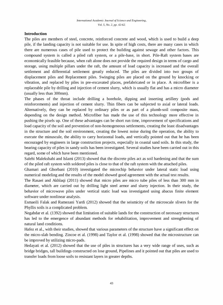
condition and condition. For example, one of the failures was the collapse of the Schwaukee Bridge piles
in the 1964 Nigata earthquake. Many researchers such as Hamada in 1992 and Ishi Hara in 1993 saw the
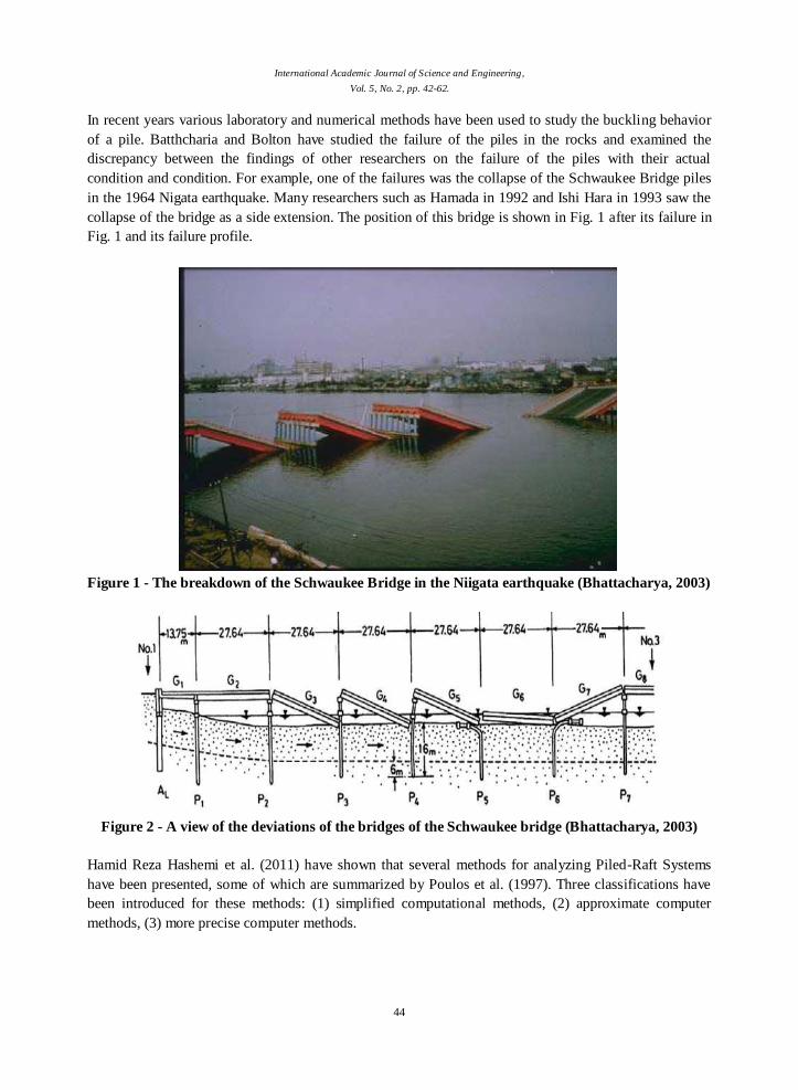
collapse of the bridge as a side extension. The position of this bridge is shown in Fig. 1 after its failure in
Fig. 1 and its failure profile.
Figure 1 - The breakdown of the Schwaukee Bridge in the Niigata earthquake (Bhattacharya, 2003)
Figure 2 - A view of the deviations of the bridges of the Schwaukee bridge (Bhattacharya, 2003)
Hamid Reza Hashemi et al. (2011) have shown that several methods for analyzing Piled-Raft Systems
have been presented, some of which are summarized by Poulos et al. (1997). Three classifications have
been introduced for these methods: (1) simplified computational methods, (2) approximate computer
methods, (3) more precise computer methods.
International Academic Journal of Science and Engineering,
Vol. 5, No. 2, pp. 42-62.
45
Simplified computational methods are presented by Poulos and (1980) Davis, (1983, 1994) Randolph,
Van Impe and Clerq (1995) and Burland (1995).
All of them include simplifying the modeling of soil profiles and loading conditions on the deck.
Approximate computer methods include two methods: (1) the "strip on springs" method, in which the
deck is routinely lined with strings that represent the hardness of the pile (e.g. 1991 Poulos) and (2) ): The
"plate on springs" method, in which the deck is designed as a plate and pile springs, such as Georgiadis
and (1998, Anagnastopoulos; (1998, Viggiani; (1994 Poulos;) Randolph and (1993, Clancy.
Computer methods are more accurate based on numerical methods. These methods include four methods:
(1) the boundary element method, where the piles and decks are both separate and use elastic theory (eg
Wiesner and Brown 1975), (Banerjee and 1971 Butterfield), (Kuwabara 1989), (Sinha 1997); (2)
Combined Boundary Elements for Pile and Finite Element for decks such as (Hain and 1987 Lee), (Ta
and 1996 Small).
(3): Simplified finite element analysis, in which the foundation system is considered as a strain-strain
problem (Desai 1974);
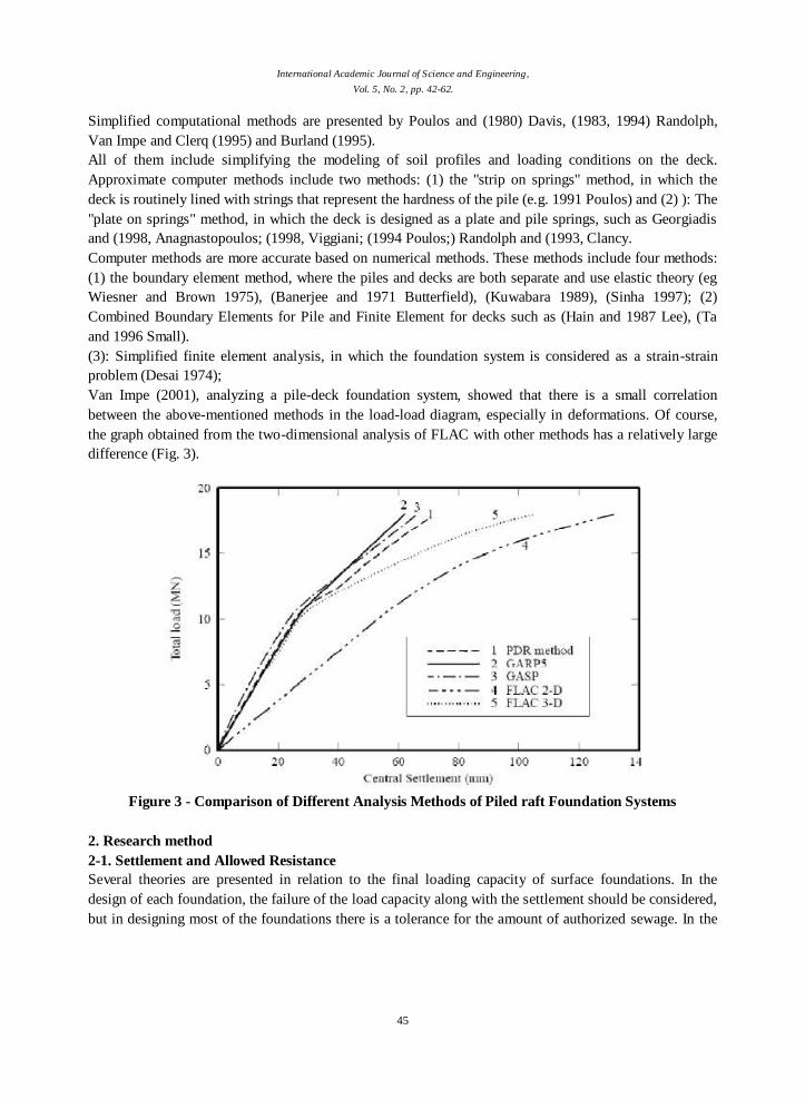
Van Impe (2001), analyzing a pile-deck foundation system, showed that there is a small correlation
between the above-mentioned methods in the load-load diagram, especially in deformations. Of course,
the graph obtained from the two-dimensional analysis of FLAC with other methods has a relatively large
difference (Fig. 3).
Figure 3 - Comparison of Different Analysis Methods of Piled raft Foundation Systems
2. Research method
2-1. Settlement and Allowed Resistance
Several theories are presented in relation to the final loading capacity of surface foundations. In the
design of each foundation, the failure of the load capacity along with the settlement should be considered,
but in designing most of the foundations there is a tolerance for the amount of authorized sewage. In the
International Academic Journal of Science and Engineering,
Vol. 5, No. 2, pp. 42-62.
46
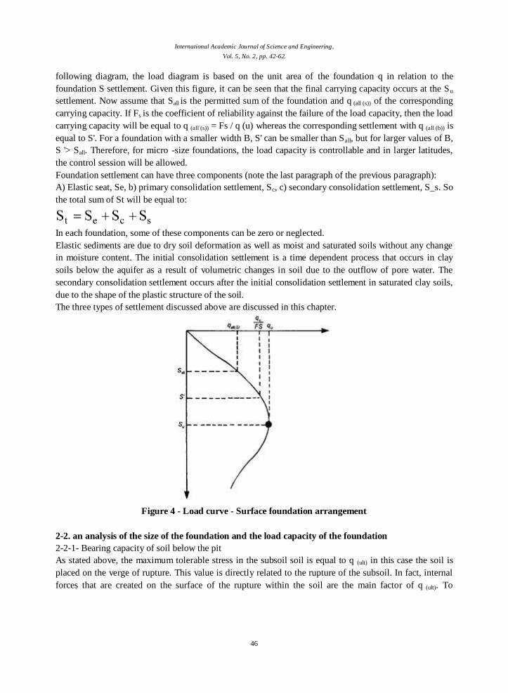
following diagram, the load diagram is based on the unit area of the foundation q in relation to the
foundation S settlement. Given this figure, it can be seen that the final carrying capacity occurs at the Su
settlement. Now assume that Sall is the permitted sum of the foundation and q (all (s)) of the corresponding
carrying capacity. If Fs is the coefficient of reliability against the failure of the load capacity, then the load
carrying capacity will be equal to q (all (s)) = Fs / q (u) whereas the corresponding settlement with q (all (b)) is
equal to S'. For a foundation with a smaller width B, S' can be smaller than Sall, but for larger values of B,
S '> Sall. Therefore, for micro -size foundations, the load capacity is controllable and in larger latitudes,
the control session will be allowed.
Foundation settlement can have three components (note the last paragraph of the previous paragraph):
A) Elastic seat, Se, b) primary consolidation settlement, Sc, c) secondary consolidation settlement, S_s. So
the total sum of St will be equal to:
In each foundation, some of these components can be zero or neglected.
Elastic sediments are due to dry soil deformation as well as moist and saturated soils without any change
in moisture content. The initial consolidation settlement is a time dependent process that occurs in clay
soils below the aquifer as a result of volumetric changes in soil due to the outflow of pore water. The
secondary consolidation settlement occurs after the initial consolidation settlement in saturated clay soils,
due to the shape of the plastic structure of the soil.
The three types of settlement discussed above are discussed in this chapter.
Figure 4 - Load curve - Surface foundation arrangement
2-2. an analysis of the size of the foundation and the load capacity of the foundation
2-2-1- Bearing capacity of soil below the pit
As stated above, the maximum tolerable stress in the subsoil soil is equal to q (ult) in this case the soil is
placed on the verge of rupture. This value is directly related to the rupture of the subsoil. In fact, internal
forces that are created on the surface of the rupture within the soil are the main factor of q (ult). To
International Academic Journal of Science and Engineering,
Vol. 5, No. 2, pp. 42-62.
47
determine q (ult) from the surface of the rupture, we go through the steps below, which is called (partial
equilibrium method).
1. We first guess the level of rupture in the subsoil soil.
2. We represent the forces on the level of rupture as a free object diagram.
3. Finally, by writing a proper equation of equation, we obtain q (ult).
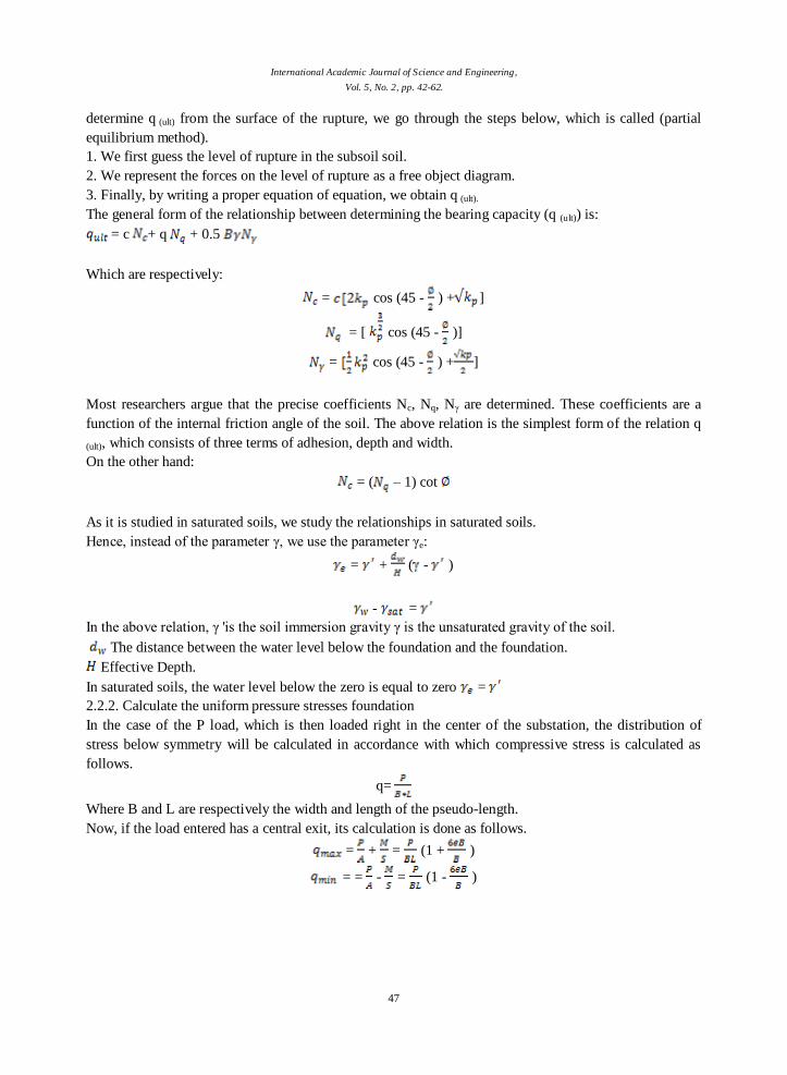
The general form of the relationship between determining the bearing capacity (q (ult)) is:
= c + q + 0.5
Which are respectively:
= cos (45 - ) + ]
= [ cos (45 - )]
= cos (45 - ) + ]
Most researchers argue that the precise coefficients Nc, Nq, Nγ are determined. These coefficients are a
function of the internal friction angle of the soil. The above relation is the simplest form of the relation q
(ult), which consists of three terms of adhesion, depth and width.
On the other hand:
= ( – 1) cot
As it is studied in saturated soils, we study the relationships in saturated soils.
Hence, instead of the parameter γ, we use the parameter γe:
= + ( - )
- =
In the above relation, γ 'is the soil immersion gravity γ is the unsaturated gravity of the soil.
The distance between the water level below the foundation and the foundation.
Effective Depth.
In saturated soils, the water level below the zero is equal to zero =
2.2.2. Calculate the uniform pressure stresses foundation
In the case of the P load, which is then loaded right in the center of the substation, the distribution of
stress below symmetry will be calculated in accordance with which compressive stress is calculated as
follows.
q=
Where B and L are respectively the width and length of the pseudo-length.
Now, if the load entered has a central exit, its calculation is done as follows.
= + = (1 + )
= = - = (1 - )
International Academic Journal of Science and Engineering,
Vol. 5, No. 2, pp. 42-62.
48
Where the eB is the exit distance from the center of the load.
Now if there is a double axis bend under the influence of the following:
= =
In the above relation, x and y are the coordinates of the point below, and Ix and Iy, the moment of inertia
is the cross section of the x and y axes.
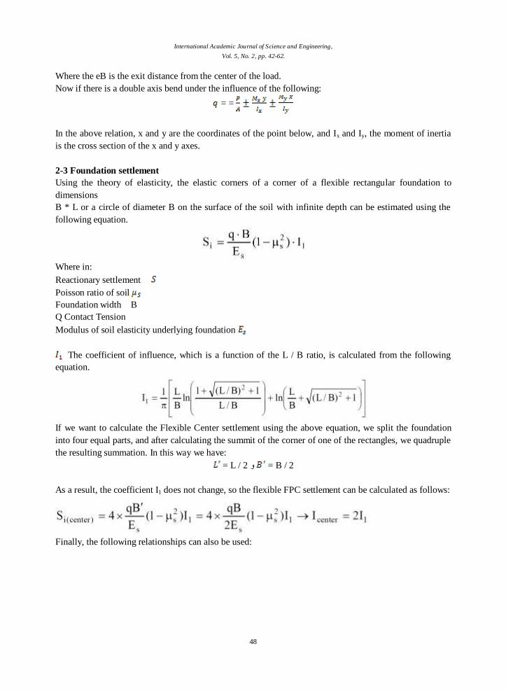
2-3 Foundation settlement
Using the theory of elasticity, the elastic corners of a corner of a flexible rectangular foundation to
dimensions
B * L or a circle of diameter B on the surface of the soil with infinite depth can be estimated using the
following equation.
Where in:
Reactionary settlement
Poisson ratio of soil
Foundation width B
Q Contact Tension
Modulus of soil elasticity underlying foundation
The coefficient of influence, which is a function of the L / B ratio, is calculated from the following
equation.
If we want to calculate the Flexible Center settlement using the above equation, we split the foundation
into four equal parts, and after calculating the summit of the corner of one of the rectangles, we quadruple
the resulting summation. In this way we have:
= L / 2 و = B / 2
As a result, the coefficient I1 does not change, so the flexible FPC settlement can be calculated as follows:
Finally, the following relationships can also be used:
International Academic Journal of Science and Engineering,
Vol. 5, No. 2, pp. 42-62.
49
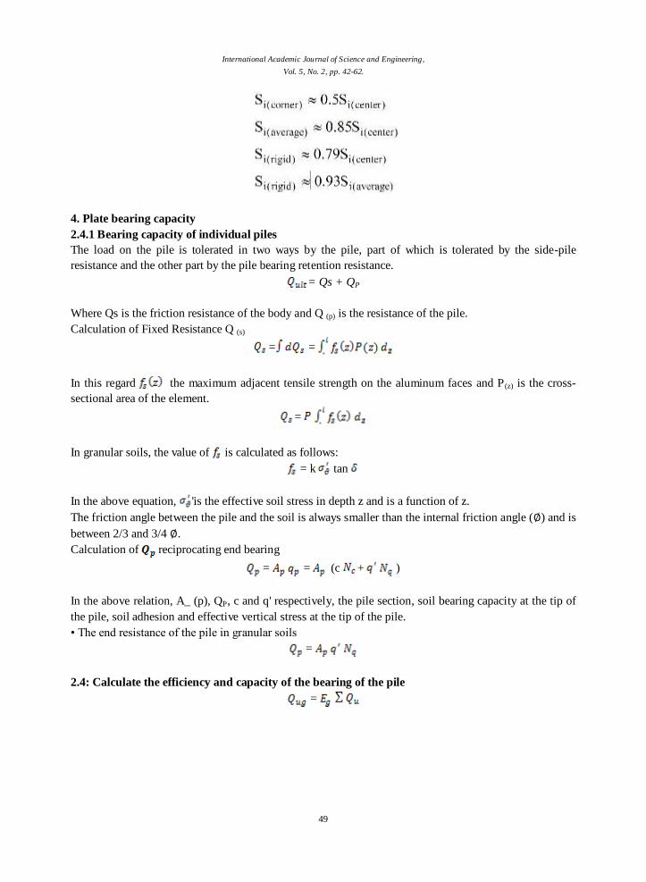
4. Plate bearing capacity
2.4.1 Bearing capacity of individual piles
The load on the pile is tolerated in two ways by the pile, part of which is tolerated by the side-pile
resistance and the other part by the pile bearing retention resistance.
= Qs + QP
Where Qs is the friction resistance of the body and Q (p) is the resistance of the pile.
Calculation of Fixed Resistance Q (s)
= =
In this regard the maximum adjacent tensile strength on the aluminum faces and P(z) is the cross-
sectional area of the element.
=
In granular soils, the value of is calculated as follows:
= k tan
In the above equation, 'is the effective soil stress in depth z and is a function of z.
The friction angle between the pile and the soil is always smaller than the internal friction angle (∅) and is
between 2/3 and 3/4 ∅.
Calculation of reciprocating end bearing
= = (c + )
In the above relation, A_ (p), QP, c and q' respectively, the pile section, soil bearing capacity at the tip of
the pile, soil adhesion and effective vertical stress at the tip of the pile.
• The end resistance of the pile in granular soils
=
2.4: Calculate the efficiency and capacity of the bearing of the pile
=
International Academic Journal of Science and Engineering,
Vol. 5, No. 2, pp. 42-62.
50
In the above relation , the bearing capacity of the pile and , the total bearing capacity of each of
the piles is normal, is also the same (efficiency) of the pile group.
=
• Elastic settlement of the pile group
The easiest way to determine the elastic enclosure of the pile group is by (tight) as follows:
= S
In the equation mentioned: Elastic settlement of the pile group Pile band section width D: The
width or diameter of each single pile in the pile group
S: A single pile of elastic settlement at the time of operation.
2-5: Modeling
To begin the modeling, we must validate the software as a whole, after validating and reaching the exact
answers that are close to the results of past research, we are beginning to build new models. In order to
validate the software used in this PIN, we will use the research done by Matsumoto et al.
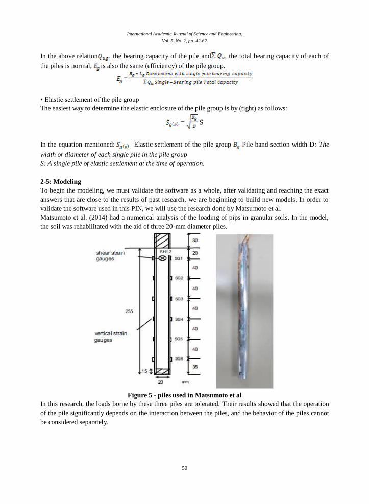
Matsumoto et al. (2014) had a numerical analysis of the loading of pips in granular soils. In the model,
the soil was rehabilitated with the aid of three 20-mm diameter piles.
Figure 5 - piles used in Matsumoto et al
In this research, the loads borne by these three piles are tolerated. Their results showed that the operation
of the pile significantly depends on the interaction between the piles, and the behavior of the piles cannot
be considered separately.
International Academic Journal of Science and Engineering,
Vol. 5, No. 2, pp. 42-62.
51
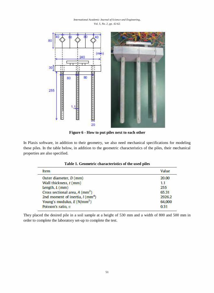
Figure 6 - How to put piles next to each other
In Plaxis software, in addition to their geometry, we also need mechanical specifications for modeling
these piles. In the table below, in addition to the geometric characteristics of the piles, their mechanical
properties are also specified.
Table 1. Geometric characteristics of the used piles
They placed the desired pile in a soil sample at a height of 530 mm and a width of 800 and 500 mm in
order to complete the laboratory set-up to complete the test.
International Academic Journal of Science and Engineering,
Vol. 5, No. 2, pp. 42-62.
52
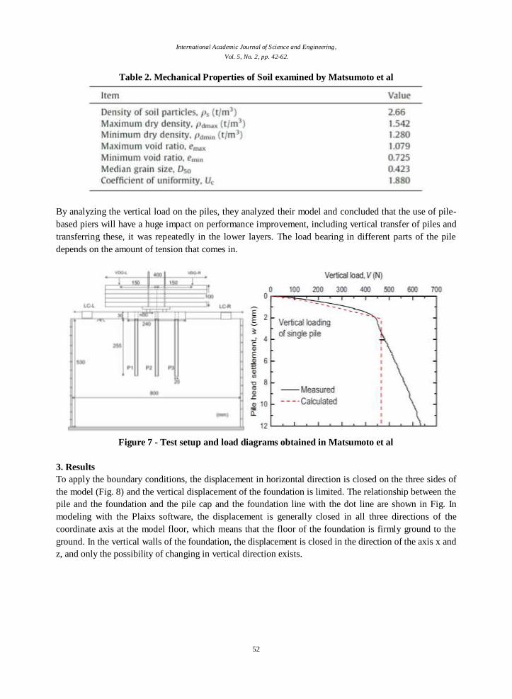
Table 2. Mechanical Properties of Soil examined by Matsumoto et al
By analyzing the vertical load on the piles, they analyzed their model and concluded that the use of pile-
based piers will have a huge impact on performance improvement, including vertical transfer of piles and
transferring these, it was repeatedly in the lower layers. The load bearing in different parts of the pile
depends on the amount of tension that comes in.
Figure 7 - Test setup and load diagrams obtained in Matsumoto et al
3. Results
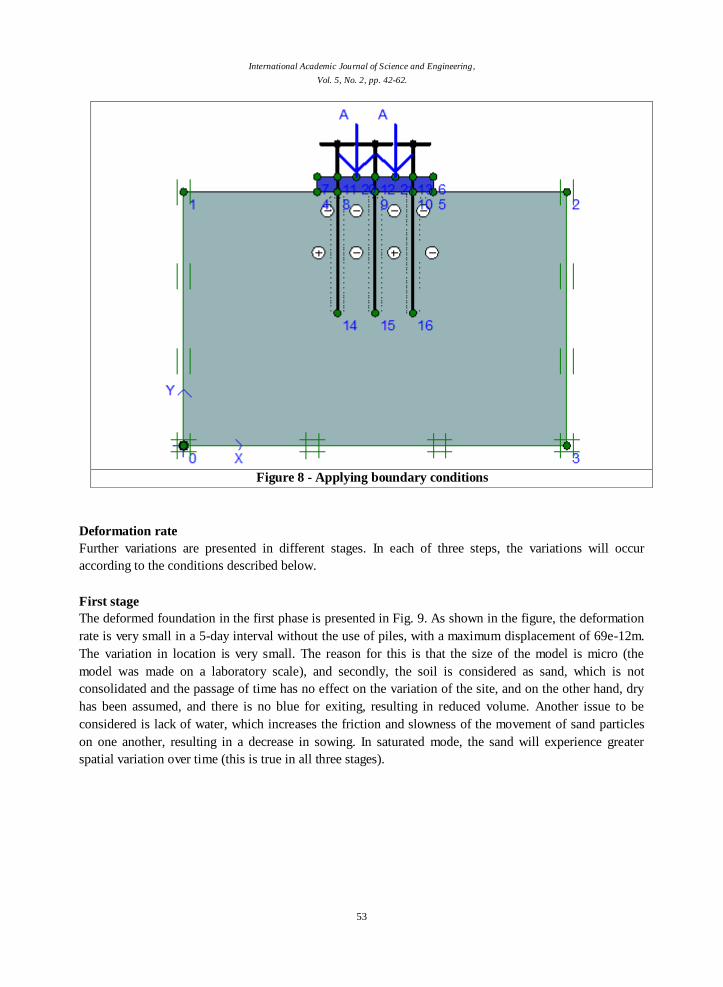
To apply the boundary conditions, the displacement in horizontal direction is closed on the three sides of
the model (Fig. 8) and the vertical displacement of the foundation is limited. The relationship between the
pile and the foundation and the pile cap and the foundation line with the dot line are shown in Fig. In
modeling with the Plaixs software, the displacement is generally closed in all three directions of the
coordinate axis at the model floor, which means that the floor of the foundation is firmly ground to the
ground. In the vertical walls of the foundation, the displacement is closed in the direction of the axis x and
z, and only the possibility of changing in vertical direction exists.
International Academic Journal of Science and Engineering,
Vol. 5, No. 2, pp. 42-62.
53
Figure 8 - Applying boundary conditions
Deformation rate
Further variations are presented in different stages. In each of three steps, the variations will occur
according to the conditions described below.
First stage
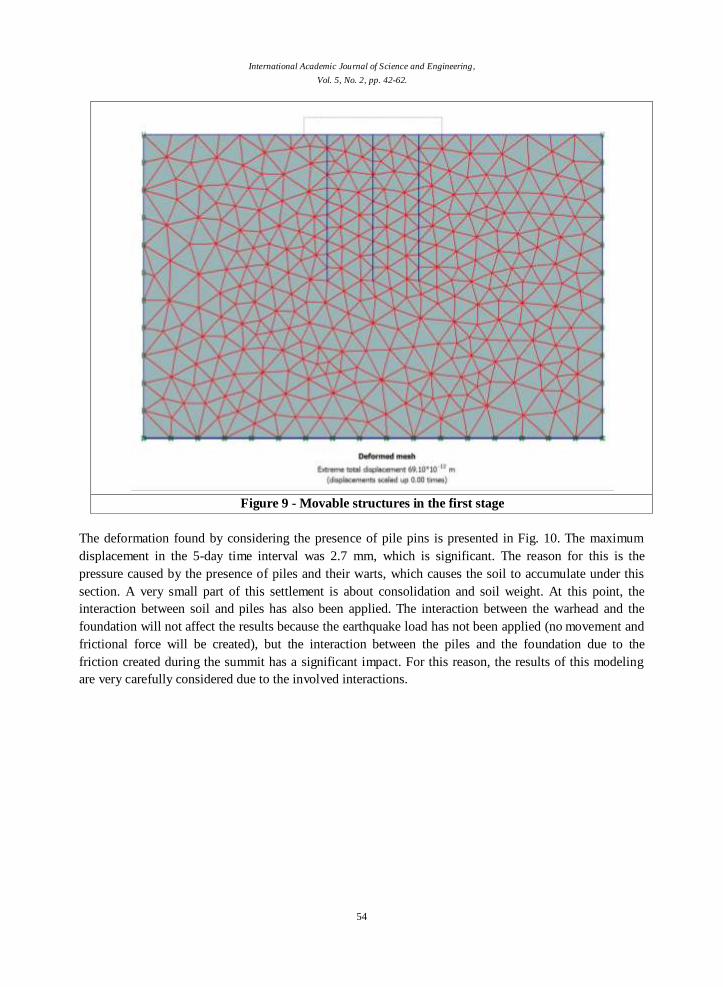
The deformed foundation in the first phase is presented in Fig. 9. As shown in the figure, the deformation
rate is very small in a 5-day interval without the use of piles, with a maximum displacement of 69e-12m.
The variation in location is very small. The reason for this is that the size of the model is micro (the
model was made on a laboratory scale), and secondly, the soil is considered as sand, which is not
consolidated and the passage of time has no effect on the variation of the site, and on the other hand, dry
has been assumed, and there is no blue for exiting, resulting in reduced volume. Another issue to be
considered is lack of water, which increases the friction and slowness of the movement of sand particles
on one another, resulting in a decrease in sowing. In saturated mode, the sand will experience greater
spatial variation over time (this is true in all three stages).
International Academic Journal of Science and Engineering,
Vol. 5, No. 2, pp. 42-62.
54
Figure 9 - Movable structures in the first stage
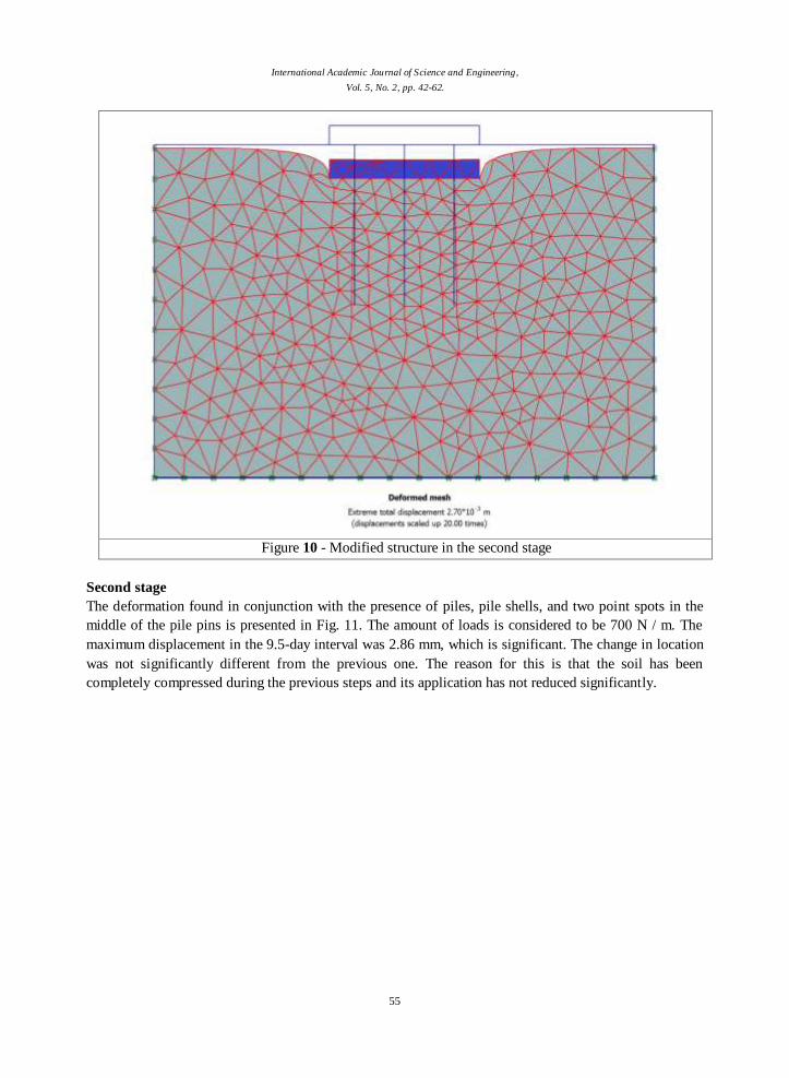
The deformation found by considering the presence of pile pins is presented in Fig. 10. The maximum
displacement in the 5-day time interval was 2.7 mm, which is significant. The reason for this is the
pressure caused by the presence of piles and their warts, which causes the soil to accumulate under this
section. A very small part of this settlement is about consolidation and soil weight. At this point, the
interaction between soil and piles has also been applied. The interaction between the warhead and the
foundation will not affect the results because the earthquake load has not been applied (no movement and
frictional force will be created), but the interaction between the piles and the foundation due to the
friction created during the summit has a significant impact. For this reason, the results of this modeling
are very carefully considered due to the involved interactions.
International Academic Journal of Science and Engineering,
Vol. 5, No. 2, pp. 42-62.
55
Figure 10 - Modified structure in the second stage
Second stage
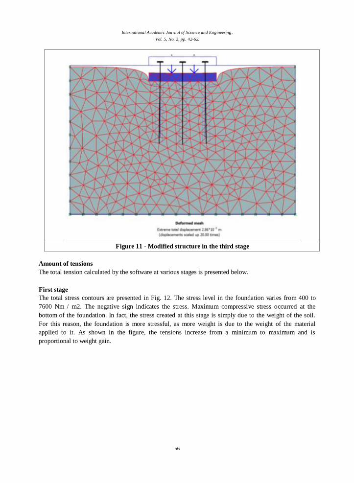
The deformation found in conjunction with the presence of piles, pile shells, and two point spots in the
middle of the pile pins is presented in Fig. 11. The amount of loads is considered to be 700 N / m. The
maximum displacement in the 9.5-day interval was 2.86 mm, which is significant. The change in location
was not significantly different from the previous one. The reason for this is that the soil has been
completely compressed during the previous steps and its application has not reduced significantly.
International Academic Journal of Science and Engineering,
Vol. 5, No. 2, pp. 42-62.
56
Figure 11 - Modified structure in the third stage
Amount of tensions
The total tension calculated by the software at various stages is presented below.
First stage
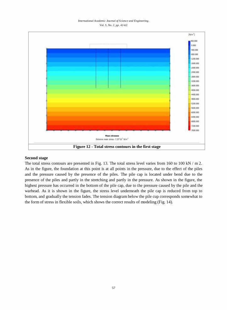
The total stress contours are presented in Fig. 12. The stress level in the foundation varies from 400 to
7600 Nm / m2. The negative sign indicates the stress. Maximum compressive stress occurred at the
bottom of the foundation. In fact, the stress created at this stage is simply due to the weight of the soil.
For this reason, the foundation is more stressful, as more weight is due to the weight of the material
applied to it. As shown in the figure, the tensions increase from a minimum to maximum and is
proportional to weight gain.
International Academic Journal of Science and Engineering,
Vol. 5, No. 2, pp. 42-62.
57
Figure 12 - Total stress contours in the first stage
Second stage
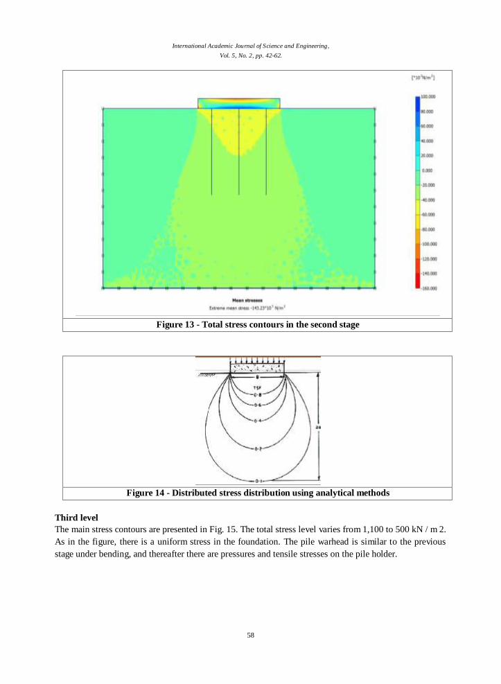
The total stress contours are presented in Fig. 13. The total stress level varies from 160 to 100 kN / m 2.
As in the figure, the foundation at this point is at all points in the pressure, due to the effect of the piles
and the pressure caused by the presence of the piles. The pile cap is located under bend due to the
presence of the piles and partly in the stretching and partly in the pressure. As shown in the figure, the
highest pressure has occurred in the bottom of the pile cap, due to the pressure caused by the pile and the
warhead. As it is shown in the figure, the stress level underneath the pile cap is reduced from top to
bottom, and gradually the tension fades. The tension diagram below the pile cup corresponds somewhat to
the form of stress in flexible soils, which shows the correct results of modeling (Fig. 14).
International Academic Journal of Science and Engineering,
Vol. 5, No. 2, pp. 42-62.
58
Figure 13 - Total stress contours in the second stage
Figure 14 - Distributed stress distribution using analytical methods
Third level
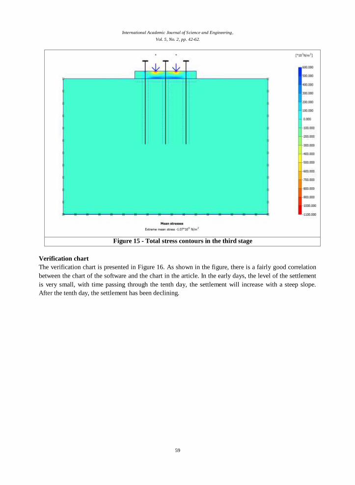
The main stress contours are presented in Fig. 15. The total stress level varies from 1,100 to 500 kN / m 2.
As in the figure, there is a uniform stress in the foundation. The pile warhead is similar to the previous
stage under bending, and thereafter there are pressures and tensile stresses on the pile holder.
International Academic Journal of Science and Engineering,
Vol. 5, No. 2, pp. 42-62.
59
Figure 15 - Total stress contours in the third stage
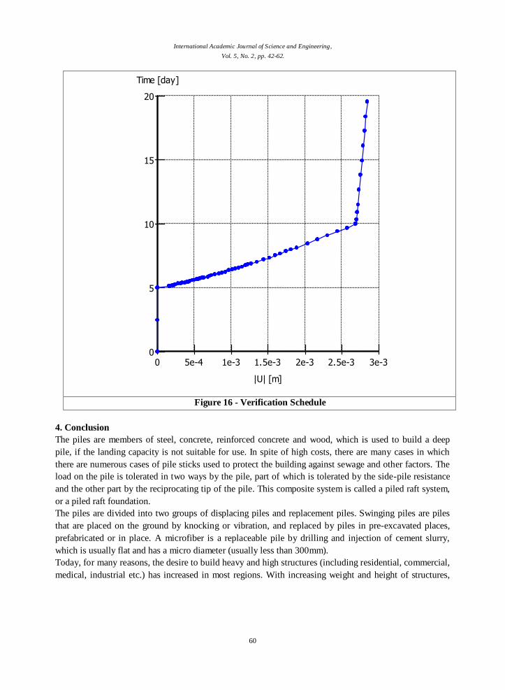
Verification chart
The verification chart is presented in Figure 16. As shown in the figure, there is a fairly good correlation
between the chart of the software and the chart in the article. In the early days, the level of the settlement
is very small, with time passing through the tenth day, the settlement will increase with a steep slope.
After the tenth day, the settlement has been declining.
International Academic Journal of Science and Engineering,
Vol. 5, No. 2, pp. 42-62.
60
0 5e-4 1e-3 1.5e-3 2e-3 2.5e-3 3e-30
5
10
15
20
|U| [m]
Time [day]
Chart 1
Curve 1
Figure 16 - Verification Schedule
4. Conclusion
The piles are members of steel, concrete, reinforced concrete and wood, which is used to build a deep
pile, if the landing capacity is not suitable for use. In spite of high costs, there are many cases in which
there are numerous cases of pile sticks used to protect the building against sewage and other factors. The
load on the pile is tolerated in two ways by the pile, part of which is tolerated by the side-pile resistance
and the other part by the reciprocating tip of the pile. This composite system is called a piled raft system,
or a piled raft foundation.
The piles are divided into two groups of displacing piles and replacement piles. Swinging piles are piles
that are placed on the ground by knocking or vibration, and replaced by piles in pre-excavated places,
prefabricated or in place. A microfiber is a replaceable pile by drilling and injection of cement slurry,
which is usually flat and has a micro diameter (usually less than 300mm).
Today, for many reasons, the desire to build heavy and high structures (including residential, commercial,
medical, industrial etc.) has increased in most regions. With increasing weight and height of structures,
International Academic Journal of Science and Engineering,
Vol. 5, No. 2, pp. 42-62.
61
other surface foundations (single, strip, wide, etc.) will not be responsive to the forces involved, and in
most cases, the use of deep foundations (piles) is required to withstand the loads.
Advantages of using micro-piles in the substrate bed are described in more detail: For new structures, the
benefits of micro-polyps can be reduced seating, increased pressure bearing, tensile load and increased
lateral load. For existing structures, the control of PIC, load control, repair or replacement of PW, PNP
control and seismic retrofit control is noted.
In this study Plaxis finite element software for modeling has been used. The results of the modeling are as
follows:
The maximum displacement is about 3 mm, which occurred at the final stage of modeling. In the first
stage, the modeling of the level of displacement is very small, due to the graininess of the soil and the dry
assumption of the material. In the second stage, the spatial variations show a sudden increase, due to the
presence of pile and the weight of the pile holder. In the third stage, the soil is completely compressed, so
the force exerted a lot of influence on the summation, and the level of the second and third phase does not
differ significantly.
In the first stage, all tensions are compressive and are due to weight of materials and the highest
tension is in the foundation. In the second step, the tension below is consistent with those recommended
in technical texts, and the tension under the pile's warhead is a bell function. In the third stage, the stress
is formed almost uniformly in the foundation, and the pile cap is bent, and partly in the pressure and
partly in the stretch. The stress level in the third stage shows a significant increase compared to the stress
level in the second stage.
References
Afshar, C., Kalantari, F., Hemmati, Ghorbani, 2008; Assessment of raft bending hardness on the bearing
capacity of the piles and the control of the overall and differential separation of raft in the
direction of the piled - Raft, 4th- National Civil Engineering Congress, University of Tehran,
Iran.
AH Pour, R., Jamei, M., Bina, M., 2010, Case study of the use of injectable micro-pads to control settling
in heavy water reservoirs in loose clay soils, Fourth International Conference on Geotechnical
Engineering and Soil Mechanics Engineering, Iran , Tehran.
Cadden, A., Gómez, J., Bruce, D., and Armour, T. (2004) Micropiles: Recent Advances and Future
Trends. Current Practices and Future Trends in Deep Foundations: pp. 140-165, doi:
10.1061/40743(142)9
Esmaeili-Falak, M., Ramezani Yardi, T. 1391; Investigating the Sewage Effect of Slabs in Susceptible
Soils of Psychoanalysis, Regional Conference on Civil Engineering, Malayer.
HAFEZ, D AND ET AL, 2012, SEISMIC RESPONSE OF GROUP OF MICROPILES CONSIDERING
PILE-CAP CONNECTIVITY CONDITIONS, Geotechnical Special Publication, ASCE.
Hashemi, H., Divine, H., Saber Mahani, M., 2011, Division of load between pile and soil in Piled Raft
foundation system with the use of micro piles, 6th National Congress of Civil Engineering,
Semnan University, Semnan, Iran.
International Academic Journal of Science and Engineering,
Vol. 5, No. 2, pp. 42-62.
62
Khushe Charkh, A., Motaqedi, S., Falahat, M., R, 2007, Investigation of the effect of the angle of gravity
on the seismic behavior of steel mill, national earthquake conference and building rehabilitation,
Behbahan.
Mansouri Kia, M., 2006; Advantages of using microfiber for the construction and stabilization of water
structures, National Conference on irrigation and drainage management, Chamran University,
Ahvaz.
Moghanloo, R., A., Imani, H., Sahar, H., 2008, Reinforcement, foundation and wall by in situ micro-
plugs, First International Conference on Seismic Rehabilitation, Tabriz, Iran.
Nazari M., A., Mahboobi Ardakani, A, R., 2009, Investigating the Seismic Behavior of micro Plates,
Eighth International Congress on Civil Engineering, Shiraz.
Noorzad, R., Sahaghi, Gh., R, 2008; Investigation of Seismic Behavior of micro Melting piles, Fourth
National Congress of Civil Engineering, University of Tehran.
Omid Ali, H., Mohammadi, S., Fakhr, A., 2011, Influence of piles on static behavior of microfiber group
in piles and decks, Journal of Civil and Surveying Engineering, No. 3, p. 279 to 290 .
Penaghi, K., Mahbubi, A., R., 2010, Analysis of the effect of the distance of piles in a pile group on
impedance and transfer functions in a model for soil- pile interaction, Fifth National Congress of
Civil Engineering, Ferdowsi University of Mashhad, Mashhad.
Qamari, A., Ghorbani, A., 2010, Real scale experiment and numerical modeling of micro -sized pile in
sandy soil, 4th International Conference on Geotechnical Engineering and Soil Mechanics,
Tehran, Tehran.
R, Ramezani Yardi, F, R, Dynamic Analysis of Seismic Performance of micro Plumbers, First National
Conference on Geotechnics, Ardebil.
Rajabi, A., R., Heydari, M., 1392, Investigating the interaction of structure-soil- pile on the response of a
pile under earthquake load, National Conference on Computational Techniques and
Optimization in Civil Engineering, Saqez.
Rasaei, et al., 2011; 2011; studying the behavior of climbing behavior under vertical load in sandy soils,
6th National Congress of Civil Engineering, Semnan University.
Salehi Malekshahi, S., Islami, A., 1392), Geotechnical performance of composite piled raft system with
consideration of the variables of soldered pile, Sharif Civil Engineering Magazine, Volume 2-29,
Issue 2.
Sirifian, S., Darabi, M., 2010, Technical and Economic Comparison of Common Cylinders and Micro
Piles (Micro Films) in Coastal Structures Using Case Studies, Fourth International Conference
on Geotechnical Engineering and Soil Mechanics, Tehran
Taylor, G. E., Gularte, F. B., and Gularte, G. G. (1998). Seismic retrofit of Fourth Street & Riverside
viaducts with micropiles, In: A. Maher and D. S. Yang (eds.). Soil Improvement for Big Digs,
Geotechnical Special Publication No. 81, ASCE, Reston, Virginia. pp. 313–325.
Zelenko, B. H., Bruce, D. A., Schoenwolf, D. A. and Traylor, R. P. (1998). Micropile applications for
seismic retrofit preserves historic structure in old San Juan, Puerto Rico, In: L. Johnsen and D.
Berry (eds.). Grouts and Grouting, Geotechnical Special Publication No. 80, ASCE, Reston,
Virginia. pp. 43–62.


![Drink Menu · overflowing ‘umami’ elements pairs well with all seafood - Dry - KIKUSUI -Junmai Ginjo- [Nigata] aromas of cantaloupe & orange mellow, crisp, slightly dry ... and](https://img.pdfslide.us/doc/110x75/5fa64663c47f8c63845521fc/drink-overflowing-aumamia-elements-pairs-well-with-all-seafood-dry-kikusui.jpg)