Embed Size (px)
Citation preview

International Academic
Journal of
Science
and
Engineering International Academic Journal of Science and Engineering Vol. 3, No. 10, 2016, pp. 30-47.
ISSN 2454-3896
30
www.iaiest.com
International Academic Institute for Science and Technology
Flow Computation of Total Head Losses and Total Pressure
Losses in a Typical Gasoline Fuel Injector System
Ejiroghne Kelly Orhorhoro
a, Ikpe Aniekan Essienubong
b, Oloke-Ehisuan
Yohannanc
aCemek Machinery Company,Benin City, Nigeria.
bDepartment of Mechanical Engineering, Coventry University, Nigeria.
cDepartment of Mechanical Engineering, Univerity of Benin, Nigeria.
Abstract
Pressure losses may result in delivery of inaccurate amount of fuel to each cylinder connected to the
engine, thereby significantly reducing the distribution of fuel to each cylinder of the engine. For a typical
gasoline port fuel injector system, there is a need for proper understanding of pressure and head losses.
This study is centred on flow computation of total head losses and total pressure losses in a typical
gasoline port fuel injector system. The pressure and head losses were calculated. The pressure losses due
to diameter expansion and contraction were negligible. Total minor head losses were calculated for the
gasoline fuel injection system, while major total pressure losses were obtained for the gasoline fuel.
Therefore, a drop in pressure will lead to decrease in thrust, and an increase in specific fuel consumption
and vice-versa.
Keywords: Pressure losses, Head Losses, Flow computation, fuel injector.
Introduction
Internal combustion engine incorporates a fuel injection system that enables the operation principles of a
typical gasoline fuel injector. Fuel injection is the introduction of fuel in an internal combustion engine
such as automobile engine, through an injector (Hardenberg, 1999). An internal combustion engine (ICE)
is an example of heat engine in which the burning or combustion of a fuel occurs via an oxidation process
usually in form of air or oxygen in a combustion chamber which make up the integral part of the working

International Academic Journal of Science and Engineering,
Vol. 3, No. 10, pp. 30-47.
31
fluid flow circuit (Suzuki, 1997). In an internal combustion engine, there is an expansion of high
temperature and pressure gases that are produced by combustion and application of direct force to some
components of the engine (Baumgarten, 2006). An injector is a kind of pump that typically includes,
steam ejector, eductor-jet pump or thermocompressor. It is of two categories namely; non-lifting and
lifting. For the lifting injector, it make uses of the venture-effect of a converging-diverging nozzle to
convert pressure energy of a motion fluid to velocity energy, which often result in development of low
pressure zone that draws in and entrains a suction fluid (Chang et al., 2007). However, for the non-lifting
injector, there is cold water-input which is fed by gravity. Non-lifting injector makes use of the principle
of induced current to push water up to the boiler check valve (Fan et al., 1999). The premature boiling of
feed water at very low absolute pressure is avoided by the venture effect (Heywood, 2000).
Port fuel injector system
In the Port Fuel Injector (PFI) system, the injector is located by the side of the intake manifold, where the
injector supplies fuel into the air inside the intake manifold. The air-fuel mixture then flows through the
intake valve and into the cylinder where one injector is mounted close to each cylinder for easy injection
of atomized fuel to the intake valve (Baumgarten, 2006). Allocation of injector to each cylinder makes it
possible for fuel distribution to occur at equal rate (Kumaravel et al., 2014). The two injectors B and D
(Figure 1) operate simultaneously at a steady flow rate of 40litres/hour from each injector and the
pressure regulator is returning 80litres/hour to the fuel tank.
Figure 1: Gasoline Port Fuel Injection System
Fuel pressure regulator
The fuel pressure regulator is an important component for any electronic fuel injector (EFI) system,
without it, the fuel rail will not be able to build up enough pressure to support the injectors with sufficient
amount of fuel. In other words, the absence of fuel pressure regulator in electronic fuel injector will

International Academic Journal of Science and Engineering,
Vol. 3, No. 10, pp. 30-47.
32
cause the inability of the fuel to reach the injectors. Moreover, it can block the flow path to the fuel tank
completely; thus, the fuel pump will try to force too much fuel into the injectors which will cause them to
fail. To accommodate a successful fuel and air mixture, a proper fuel pressure is required in all situations,
both at low and high revs, regardless of the power output. This is where the fuel pressure regulator is
doing its job, to adapt the fuel supply to the fuel demand (Cengel et al., 2012). Therefore, it become
necessary to determine the pressure and head losses in a typical gasoline fuel injector system.
Assumptions made
The following assumptions were made to determine the losses.
i. The flow through the system is steady.
ii. The flow is incompressible i.e. Ma 0.3
iii. Flow is fully developed, and the entrance effect is neglected.
iv. Supply temperature is 210C
v. The density of gasoline at supply temperature is 744.7168kg/m3
vi. Dynamic viscosity of gasoline is constant for the flow and taken as = 1.895 x 10⁻⁵
kg/m.s
vii. Material for the entire fuel supply system is copper and the roughness value is 0.0025mm
viii. Assume that the discharge coefficient is 0.5.
ix. Throughout all the system, head loses from diameter changes is very small and negligible.
x. The pipe connecting fuel pump to fuel filter is assumed to have equal length and diameter with that
connecting the fuel filter to the fuel rail.
Nozzle diameter To deliver 40litres/hour of gasoline at injectors B and D simultaneously as well as return 80litres/hour of
gasoline at the pressure regulator to the fuel tank, the pump must supply enough work to overcome the
pressure drop in the flow.
The volume flow rate at the nozzle
(1)
Recall that the actual mass flow rate entering into the injector is a fraction of the supply,
(2)
Where;
= actual mass flow rate
= coefficient of discharge
= Density of the fluid
= Volume flow rate
Also,

International Academic Journal of Science and Engineering,
Vol. 3, No. 10, pp. 30-47.
33
(Massey and Ward-Smith, 2006) (3)
Where;
And,
= Discharge velocity
Given that:
Then,
(4)
The nozzle diameter to produce 25m/s discharge is therefore 0.531mm
Pressure drop calculation
The total pressure loss in the system is the sum of all the pressure loss across each element of the
injection system. To calculate the total pressure loss in the system the losses are categorised as follows.
i. Pressure loss between fuel pump to fuel filter
ii. Pressure loss at the fuel filter
iii. Pressure loss between the fuel filter and the fuel rail Pressure loss
iv. Pressure loss at the fuel rail
v. Pressure loss at the injectors
vi. Pressure loss between the rail pipe and the fuel tank
vii. Pressure loss at the fuel regulator
Pressure Loss between Fuel Pump and Fuel Filter
For this kind of setup, at the pump, there will be pressure losses over the pipe length, pressure losses at
the bends and pressure loss due to sudden change in diameter at the entrance and exit of the fittings.
Therefore;
(5)
There is a single pipe connecting the fuel pump to the fuel filter. The pipe is assumed to have equal length
and diameter with that connecting the fuel filter to the fuel rail. The pipe has two bends of 90 degrees
each. For this kind of setup, there will be pressure losses over the pipe length, pressure losses at the bends
while the pressure loss due to changing diameter is neglected. Considering the pressure loss due to the
sudden expansion and contraption at the fittings to be very minimal, the pressure loss due to diameter
International Academic Journal of Science and Engineering,
Vol. 3, No. 10, pp. 30-47.
34
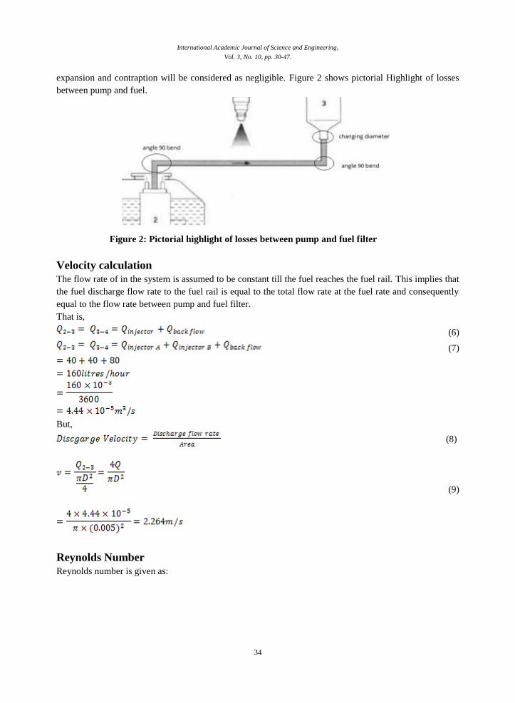
expansion and contraption will be considered as negligible. Figure 2 shows pictorial Highlight of losses
between pump and fuel.
Figure 2: Pictorial highlight of losses between pump and fuel filter
Velocity calculation
The flow rate of in the system is assumed to be constant till the fuel reaches the fuel rail. This implies that
the fuel discharge flow rate to the fuel rail is equal to the total flow rate at the fuel rate and consequently
equal to the flow rate between pump and fuel filter.
That is,
(6)
(7)
But,
(8)
(9)
Reynolds Number
Reynolds number is given as:
International Academic Journal of Science and Engineering,
Vol. 3, No. 10, pp. 30-47.
35
(10)
Where,
µ= Kinematic Viscosity for gasoline which is
ρ = Density for gasoline which is 744.7168 kg/m3
D is the diameter of the pipe in meters
Since the Reynolds number Re ˃> 4,000, this simply shows that the flow is turbulent. For a laminar flow
to occur, Re must be less than 4,000.
Pressure Losses over the Pipe Length
Pressure loss in pipes is given as;
(11)
Where:
(12)
L is the length of the pipe in meters
D is the diameter of the pipe in meters
V is the velocity of the flow through the pipe
is the Reynolds number and is given as
ԑ: Surface Roughness (0.0025 x 10⁻³
m)

International Academic Journal of Science and Engineering,
Vol. 3, No. 10, pp. 30-47.
36
The major head loss is therefore1.11m
Pressure losses due to bends
The pressure losses due to bend is one of the many minor losses in flow of fluid through pipes. The
representation in Figure 3 shows two location of such bend between the pump and the filter.
The two minor losses due to the 900 bends which can be estimated as,
(13)
Where:
is the frictional factor due to flow across bends and is given 1.1 for 900 bends without vanes as shown
in Figure 3.
Figure 3: value for pipe bends (Cengel et al., 2012)
International Academic Journal of Science and Engineering,
Vol. 3, No. 10, pp. 30-47.
37
Total Pressure loss
There will be pressure losses over the pipe length, pressure losses at the bends and pressure loss due to
sudden change in diameter at the entrance and exit of the fittings.
Therefore;
(14)
The total pressure loss is given as
(15)
Pressure Loss at the Fuel Filter Given that;
At the pressure drop is 0.35psi
Then at ,
If the relationship between pressure drop and flow rate is linear,
Then
But,
Then:
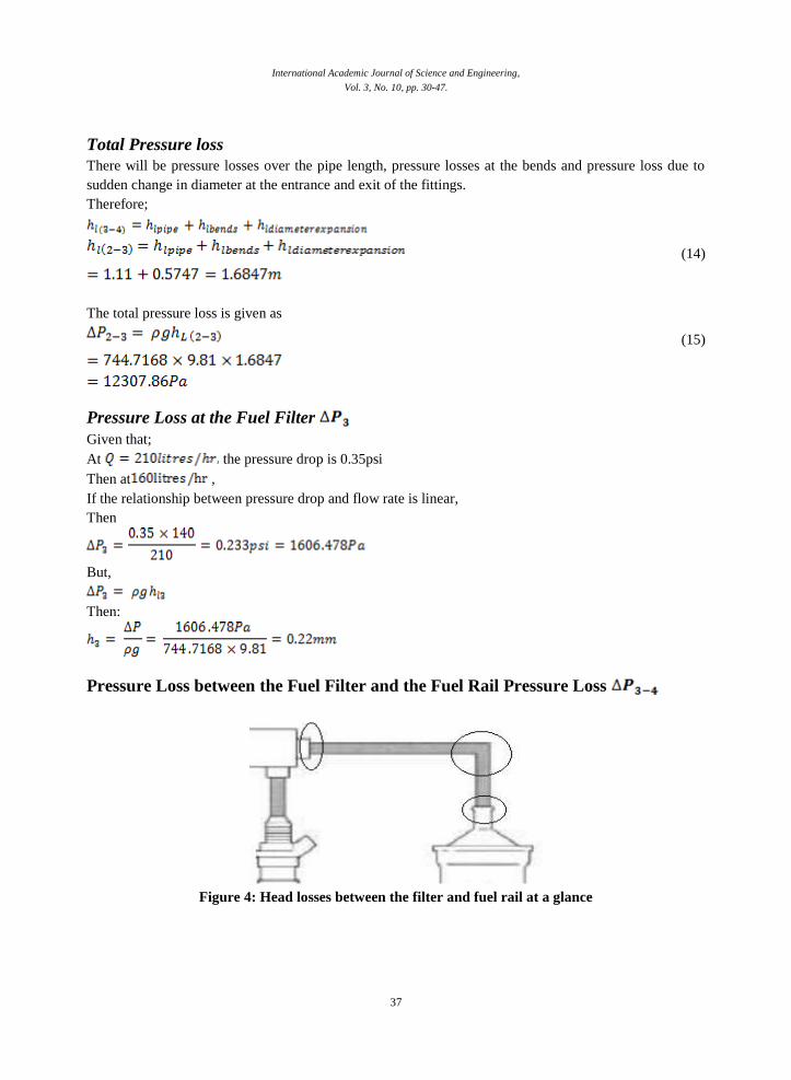
Pressure Loss between the Fuel Filter and the Fuel Rail Pressure Loss
Figure 4: Head losses between the filter and fuel rail at a glance
International Academic Journal of Science and Engineering,
Vol. 3, No. 10, pp. 30-47.
38
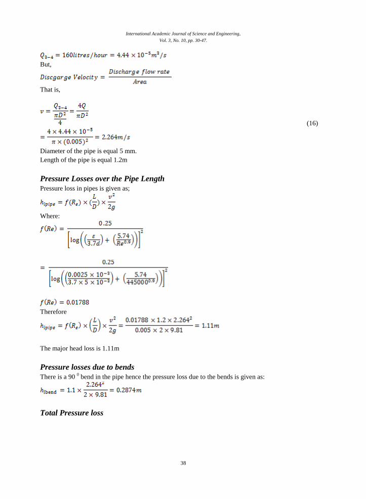
But,
That is,
(16)
Diameter of the pipe is equal 5 mm.
Length of the pipe is equal 1.2m
Pressure Losses over the Pipe Length
Pressure loss in pipes is given as;
Where:
Therefore
The major head loss is 1.11m
Pressure losses due to bends
There is a 90 0 bend in the pipe hence the pressure loss due to the bends is given as:
Total Pressure loss

International Academic Journal of Science and Engineering,
Vol. 3, No. 10, pp. 30-47.
39
The total pressure loss is given as:
Pressure loss at the fuel rail
Diameter of the common rail is equal 12 mm.
Length is equal 0.36 m
But,
That is,
Reynolds number is given as:
Re ˃> 4,000, therefore the flow is said to be turbulent
There will be pressure losses over the pipe length, pressure losses at the bends and pressure loss due to
sudden change in diameter at the entrance and exit of the common rail and the feed of the injector.
Therefore;
Figure 5 shows the head losses between fuel rail at a glance

International Academic Journal of Science and Engineering,
Vol. 3, No. 10, pp. 30-47.
40
Figure 6: Head losses between fuel rails at a glance
Pressure Losses over the Pipe Length
Pressure loss in pipes is given as;
Where:

International Academic Journal of Science and Engineering,
Vol. 3, No. 10, pp. 30-47.
41
The major head loss is 0.00411m
Pressure losses due to bends
The pressure losses due to bend is one of the many minor losses in flow of fluid through pipes. The
representation in Figure 6 shows two tee bends at the edge of the injectors.
The two minor losses due to bends can be estimated by:
(17)
Where:
KL: is the frictional factor due to flow across bends and is given as 1 for the friction due to bends which is
equal to 1 for 900 bends without vanes.
Figure 7: value for pipe tee-bends (Cengel et al., 2012)
Pressure losses due to abrupt Expansion (changing in diameter)
The diameter expansion occurs between 5mm and 12mm at the fuel rail

International Academic Journal of Science and Engineering,
Vol. 3, No. 10, pp. 30-47.
42
Total Pressure loss
The total pressure loss is given as:
Pressure loss at the injectors P injectors
Diameter is equal 5 mm (0.005m).
Length is equal 70 mm (0.07m)
Velocity Calculation
The flow rate of the injector is 40litres/hr
But,
That is,
Reynolds Number
Reynolds number is given as:
D is the diameter of the pipe in meters
Re ˃> 4,000, therefore the flow is said to be turbulent

International Academic Journal of Science and Engineering,
Vol. 3, No. 10, pp. 30-47.
43
Pressure loss in the injector is given as;
Where:
Therefore,
The total pressure loss is given as:
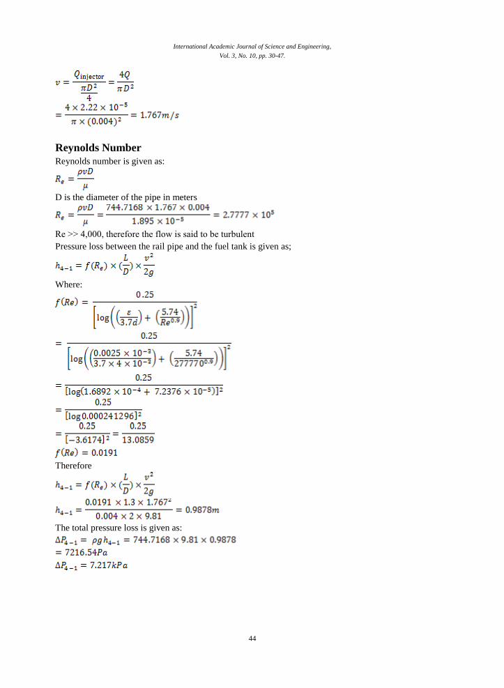
Pressure loss between the rail pipe and the fuel tank
Diameter is equal 4 mm (0.004 m).
Length is equal 1.3m
Velocity Calculation
The return flow rate 80litres/hr
But,
That is,
International Academic Journal of Science and Engineering,
Vol. 3, No. 10, pp. 30-47.
44
Reynolds Number
Reynolds number is given as:
D is the diameter of the pipe in meters
Re ˃> 4,000, therefore the flow is said to be turbulent
Pressure loss between the rail pipe and the fuel tank is given as;
Where:
Therefore
The total pressure loss is given as:

International Academic Journal of Science and Engineering,
Vol. 3, No. 10, pp. 30-47.
45
Calculation of minor loss
Assumptions
Pressure relief valve used in cars is a sophisticated kind of valve, it is not a simple valve used in
regulating pressure in simple pipe flows. It was assumed as a diaphragm attached with the ‘’ball seat’’ by-
pass valve (Cengel et al., 2012). But for the simplicity we took only the ball seat by-pass valve and thus
considering the minor loss across it. There are different types of ball valves but we assumed the 1/3
closed ball valve because the other type is fully open valve, is going to be too humble to let fuel pass
through it as if a little pressure is exerted by the fuel pump. Where the 2/3closed ball valve is going to be
too harsh to let fuel at critical or high speed running of the engine and thus it can damage the fuel
injectors at high speed. We need a balance between them so it can operate well in both the cases and thus
1/3 closed ball valve can serve the purpose well enough. From the valves and fitting chart the minor loss
coefficient came out to be 5.5 for the Ball valve, 1/3 closed (Cengel et al., 2012).
(15)
Where kb is the loss coefficient for 1/3 closed ball valve which from the chart is 5.5.
As we know the pressure regulator is placed on the return pipe so by taking it’s diameter for calculating
the velocity.
Here V is unknown so from continuity equation:
Get
(16)
By putting the values,
(17)
By putting equation (17) in equation (16)
By putting the value of equation (16) and kb in equation (15),
The total pressure loss is given as:

International Academic Journal of Science and Engineering,
Vol. 3, No. 10, pp. 30-47.
46
Table 1 shows the summary of head losses calculated for the engine fuel system
Table 1: Summary of head losses for the engine fuel system
The total head loss for the Gasoline Port Fuel Injection System is hl (total) = 5.2321m
The total pressure loss for the Gasoline Port Fuel Injection System is P total = 38223.318Pa
Conclusion
The flow rate of the system was constant till the fuel reaches the fuel rail. This implies that the fuel
discharge flow rate to the fuel rail is equal to the total flow rate at the fuel rate and consequently equal to
the flow rate between pump and fuel filter. Throughout the analysis, Re ˃> 4,000 was obtained, this
implies that the flow is turbulent. Thus, the presence of bends observed. The minor head losses are caused
by frictional loses due to bends and the change in diameters. However, for the major head losses such as
pressure losses, it was due to frictional loses in the pipes due to the fluid to overcome shear viscous
resistance resulting from shear and normal forces of the pipe internal surface.
References:
Baumgarten, C. (2006) Mixture Formation in Internal Combustion Engines, Springer Verlag,

International Academic Journal of Science and Engineering,
Vol. 3, No. 10, pp. 30-47.
47
Cengel, Y., Cimbala, J., Turner, R., and Kanoglu, M. (2012). Thermo-FluidSciences. MgGraw-Hill,
Newyork
Fan L., Li G., Han Z. and Reitz R. D. (1999) Modeling Fuel Preparation and Stratified Combustion in a
Gasoline Direct Injection Engine, SAE Paper 1999-01-0175.
Germany.Chang W. S., Kim Y. N. and Kong J. K. (2007) Design and Development of a Central Direct
Injection Stratified Gasoline Engine, SAE Paper 01-3531.
Goldfinch and Semmens (2000). How Steam Locomotives Really Work. Oxford University Press.
pp. 92–97. ISBN 978-0-19-860782-3
Hardenberg, H.O. (1999). The Middle Ages of the Internal Combustion Engine. US: Society of
Automotive Engineers.
Heywood J. B. (2000) Internal Combustion Engines Fundamentals, McGraw Hill Book, Singapore.
Kumaravel, K., Saravanan, G. G., Premanand, B. (2014) Experimental Studies on the Comparison of
Static Fuel Injection Characteristics of Fuel Injectors Used in GDI Engine 1 (4) 2249-9954
Massey, B. and Ward-Smith, A. (2006). Mechanics of fluids. London: Taylor &
Francis.
Usha Madhuri T, Srinivas T and Ramakrishna K,(2003). A study on automobile exhaust pollution with
regard to carbon monoxide emissions, Nature, Environmental and Poll Tech, 2, 473-474.
Suzuki, T. (1997). The Romance of Engines. US: Society of Automotive Engineers. ISBN I-56091-911-6