Embed Size (px)
Citation preview
E x c e l l e n t T e c h n o l o g y , E f f i c i e n c y a n d Q u a l i t y
INVERTRONIC modular Three Phase Inverter System with Modular, Hot-Plug Design
Wor ld C lass Power So lu t ions
2
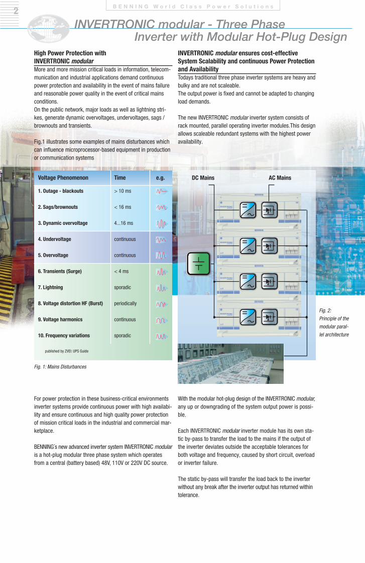
Fig. 1: Mains Disturbances
Fig. 2: Principle of themodular paral-lel architecture
DC Mains AC Mains
For power protection in these business-critical environmentsinverter systems provide continuous power with high availabi-lity and ensure continuous and high quality power protectionof mission critical loads in the industrial and commercial mar-ketplace.
BennInG´s new advanced inverter system InVertronIc modularis a hot-plug modular three phase system which operatesfrom a central (battery based) 48V, 110V or 220V Dc source.
INVERTRONIC modular - Three Phase Inverter with Modular Hot-Plug Design
High Power Protection with INVERTRONIC modularMore and more mission critical loads in information, telecom-munication and industrial applications demand continuouspower protection and availability in the event of mains failureand reasonable power quality in the event of critical mainsconditions. on the public network, major loads as well as lightning stri-kes, generate dynamic overvoltages, undervoltages, sags /brownouts and transients.
Fig.1 illustrates some examples of mains disturbances whichcan influence microprocessor-based equipment in productionor communication systems
With the modular hot-plug design of the InVertronIc modular,any up or downgrading of the system output power is possi-ble.
each InVertronIc modular inverter module has its own sta-tic by-pass to transfer the load to the mains if the output ofthe inverter deviates outside the acceptable tolerances forboth voltage and frequency, caused by short circuit, overloador inverter failure.
the static by-pass will transfer the load back to the inverterwithout any break after the inverter output has returned within tolerance.
INVERTRONIC modular ensures cost-effective System Scalability and continuous Power Protectionand Availability todays traditional three phase inverter systems are heavy andbulky and are not scaleable.the output power is fixed and cannot be adapted to changingload demands.
the new InVertronIc modular inverter system consists ofrack mounted, parallel operating inverter modules.this designallows scaleable redundant systems with the highest poweravailability.
B E N N I N G W o r l d C l a s s P o w e r S o l u t i o n s
Voltage Phenomenon
1. Outage - blackouts
2. Sags/brownouts
3. Dynamic overvoltage
4. Undervoltage
5. Overvoltage
6. Transients (Surge)
7. Lightning
8. Voltage distortion HF (Burst)
9. Voltage harmonics
10. Frequency variations
Time
> 10 ms
< 16 ms
4...16 ms
continuous
continuous
< 4 ms
sporadic
periodically
continuous
sporadic
e.g.
published by ZVeI: UPS Guide
25 50 75 100
82
84
86
88
90
92
3
output power [%]
[%]
effic
ienc
y
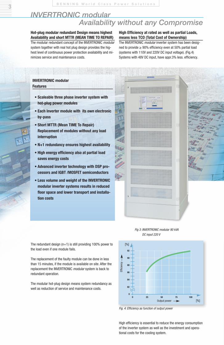
FIg 3: INVERTRONIC modular 90 kVA DC input 220 V
Fig. 4: Efficiency as function of output power
Hot-plug modular redundant Design means highestAvailability and short MTTR (MEAN TIME TO REPAIR)the modular redundant concept of the InVertronIc modularsystem together with real hot plug design provides the hig-hest level of continuous power protection availability and mi-nimizes service and maintenance costs.
the redundant design (n+1) is still providing 100% power tothe load even if one module fails.
the replacement of the faulty module can be done in lessthan 15 minutes, if the module is available on site. After thereplacement the InVertronIc modular system is back to redundant operation.
the modular hot-plug design means system redundancy aswell as reduction of service and maintenance costs.
High efficiency is essential to reduce the energy consumptionof the inverter system as well as the investment and opera-tional costs for the cooling system.
High Efficiency at rated as well as partial Loads,means less TCO (Total Cost of Ownership) the InVertronIc modular inverter system has been desig-ned to provide ≥ 90% efficiency even at 50% partial load(systems with 110V and 220V Dc input voltage). (Fig.4)Systems with 48V Dc input, have appr.3% less. efficiency.
INVERTRONIC modular Availability without any Compromise
B E N N I N G W o r l d C l a s s P o w e r S o l u t i o n s
INVERTRONIC modularFeatures
• Scaleable three phase inverter system withhot-plug power modules
• Each Inverter module with its own electronicby-pass
• Short MTTR (Mean TIME To Repair) Replacement of modules without any load interruption
• N+1 redundancy ensures highest availability
• High energy efficiency also at partial loadsaves energy costs
• Advanced inverter technology with DSP pro-cessors and IGBT /MOSFET semiconductors
• Less volume and weight of the INVERTRONICmodular inverter systems results in reducedfloor space and lower transport and installa-tion costs
54INVERTRONIC modular
Simple Operation, Rapid Diagnosis
B E N N I N G W o r l d C l a s s P o w e r S o l u t i o n s
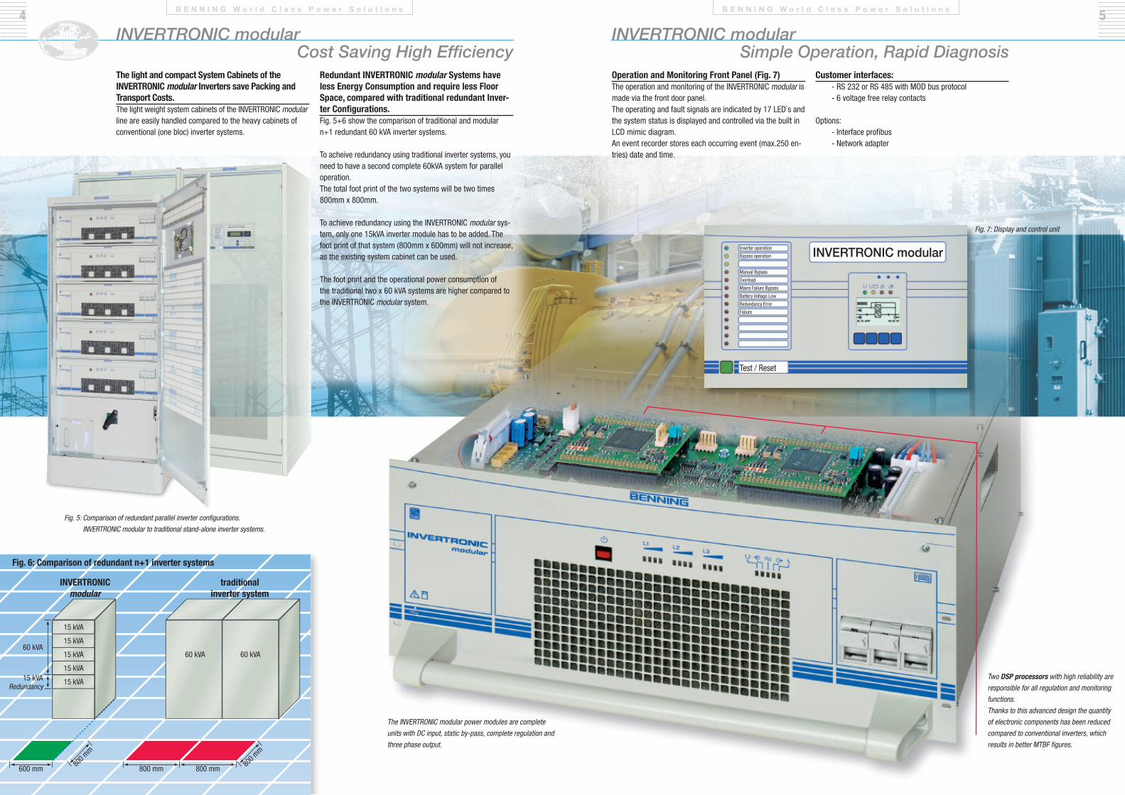
Fig. 5: Comparison of redundant parallel inverter configurations. INVERTRONIC modular to traditional stand-alone inverter systems.
The INVERTRONIC modular power modules are completeunits with DC input, static by-pass, complete regulation andthree phase output.
Inverter operation
Bypass operation
Manual Bypass
Overload
Mains Failure Bypass
Battery Voltage Low
Redundancy Error
Failure
Test / Reset
INVERTRONIC modular
Fig. 7: Display and control unit
Operation and Monitoring Front Panel (Fig. 7)The operation and monitoring of the INVERTRONIC modular ismade via the front door panel.The operating and fault signals are indicated by 17 LED`s andthe system status is displayed and controlled via the built inLCD mimic diagram.An event recorder stores each occurring event (max.250 en-tries) date and time.
Customer interfaces:- RS 232 or RS 485 with MOD bus protocol- 6 voltage free relay contacts
Options:- Interface profibus - Network adapter
Two DSP processors with high reliability areresponsible for all regulation and monitoringfunctions.Thanks to this advanced design the quantityof electronic components has been reducedcompared to conventional inverters, whichresults in better MTBF figures.
INVERTRONIC modular Cost Saving High Efficiency
B E N N I N G W o r l d C l a s s P o w e r S o l u t i o n s
Redundant INVERTRONIC modular Systems haveless Energy Consumption and require less FloorSpace, compared with traditional redundant Inver-ter Configurations. Fig. 5+6 show the comparison of traditional and modularn+1 redundant 60 kVA inverter systems.
To acheive redundancy using traditional inverter systems, youneed to have a second complete 60kVA system for paralleloperation. The total foot print of the two systems will be two times800mm x 800mm.
To achieve redundancy using the INVERTRONIC modular sys-tem, only one 15kVA inverter module has to be added. Thefoot print of that system (800mm x 600mm) will not increase,as the existing system cabinet can be used.
The foot print and the operational power consumption of the traditional two x 60 kVA systems are higher compared to the INVERTRONIC modular system.
The light and compact System Cabinets of the INVERTRONIC modular Inverters save Packing andTransport Costs. The light weight system cabinets of the INVERTRONIC modularline are easily handled compared to the heavy cabinets ofconventional (one bloc) inverter systems.
Fig. 6: Comparison of redundant n+1 inverter systems
INVERTRONIC modular
Redundancy
traditionalinverter system
20
40
60
80
100
0.6 0.8 1.0 0.8 0.6
6
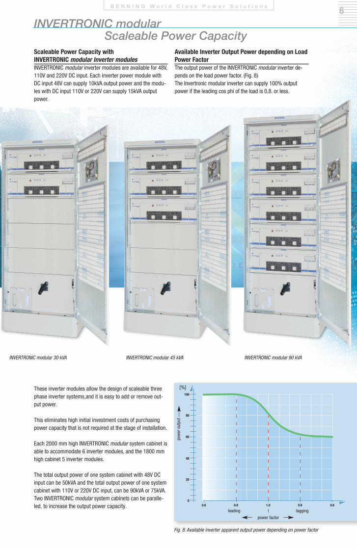
these inverter modules allow the design of scaleable threephase inverter systems,and it is easy to add or remove out-put power.
this eliminates high initial investment costs of purchasingpower capacity that is not required at the stage of installation.
each 2000 mm high InVertronIc modular system cabinet isable to accommodate 6 inverter modules, and the 1800 mmhigh cabinet 5 inverter modules.
the total output power of one system cabinet with 48V Dcinput can be 50kVA and the total output power of one systemcabinet with 110V or 220V Dc input, can be 90kVA or 75kVA.two InVertronIc modular system cabinets can be paralle-led, to increase the output power capacity.
Scaleable Power Capacity with INVERTRONIC modular Inverter modulesInVertronIc modular inverter modules are available for 48V,110V and 220V Dc input. each inverter power module withDc input 48V can supply 10kVA output power and the modu-les with Dc input 110V or 220V can supply 15kVA outputpower.
Available Inverter Output Power depending on LoadPower Factorthe output power of the InVertronIc modular inverter de-pends on the load power factor. (Fig. 8)the Invertronic modular inverter can supply 100% outputpower if the leading cos phi of the load is 0,8. or less.
INVERTRONIC modular 30 kVA
Fig. 8: Available inverter apparent output power depending on power factor
INVERTRONIC modular 45 kVA INVERTRONIC modular 90 kVA
INVERTRONIC modular Scaleable Power Capacity
B E N N I N G W o r l d C l a s s P o w e r S o l u t i o n s
leading lagging
power factor
[%]
pow
er o
utpu
t
7
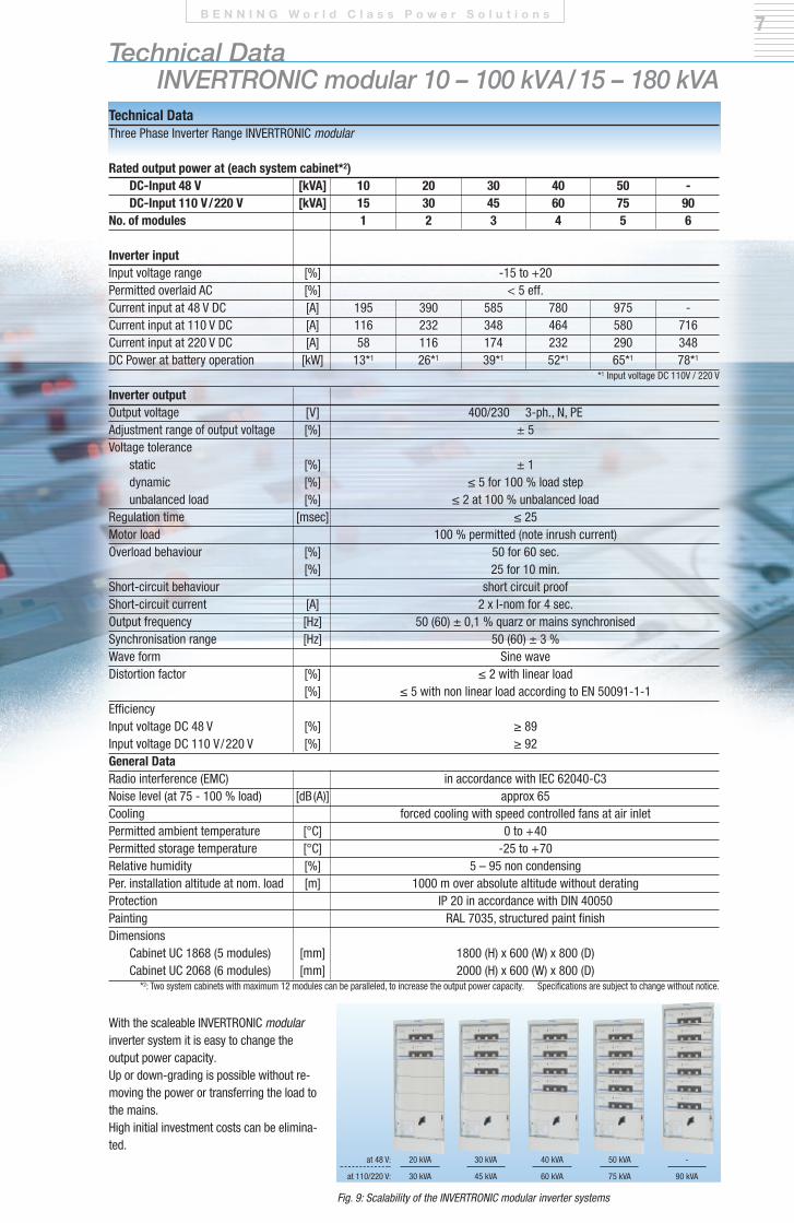
Rated output power at (each system cabinet*2)DC-Input 48 V [kVA] 10 20 30 40 50 - DC-Input 110 V/220 V [kVA] 15 30 45 60 75 90
No. of modules 1 2 3 4 5 6
Inverter input Input voltage range [%] -15 to +20 Permitted overlaid Ac [%] < 5 eff.current input at 48 V Dc [A] 195 390 585 780 975 -current input at 110 V Dc [A] 116 232 348 464 580 716current input at 220 V Dc [A] 58 116 174 232 290 348Dc Power at battery operation [kW] 13*1 26*1 39*1 52*1 65*1 78*1
*1 Input voltage Dc 110V / 220 V
Inverter output output voltage [V] 400/230 3-ph., n, Pe Adjustment range of output voltage [%] ± 5Voltage tolerance
static [%] ± 1 dynamic [%] ≤ 5 for 100 % load step unbalanced load [%] ≤ 2 at 100 % unbalanced load
regulation time [msec] ≤ 25 Motor load 100 % permitted (note inrush current) overload behaviour [%] 50 for 60 sec.
[%] 25 for 10 min.Short-circuit behaviour short circuit proofShort-circuit current [A] 2 x I-nom for 4 sec. output frequency [Hz] 50 (60) ± 0,1 % quarz or mains synchronisedSynchronisation range [Hz] 50 (60) ± 3 %Wave form Sine waveDistortion factor [%] ≤ 2 with linear load
[%] ≤ 5 with non linear load according to en 50091-1-1 efficiencyInput voltage Dc 48 V [%] ≥ 89 Input voltage Dc 110 V/220 V [%] ≥ 92 General Dataradio interference (eMc) in accordance with Iec 62040-c3 noise level (at 75 - 100 % load) [dB(A)] approx 65 cooling forced cooling with speed controlled fans at air inletPermitted ambient temperature [°c] 0 to +40 Permitted storage temperature [°c] -25 to +70 relative humidity [%] 5 – 95 non condensing Per. installation altitude at nom. load [m] 1000 m over absolute altitude without deratingProtection IP 20 in accordance with DIn 40050Painting rAL 7035, structured paint finishDimensions
cabinet Uc 1868 (5 modules) [mm] 1800 (H) x 600 (W) x 800 (D) cabinet Uc 2068 (6 modules) [mm] 2000 (H) x 600 (W) x 800 (D)
*2: two system cabinets with maximum 12 modules can be paralleled, to increase the output power capacity. Specifications are subject to change without notice.
Technical Data three Phase Inverter range InVertronIc modular
Technical Data INVERTRONIC modular 10 – 100 kVA/15 – 180 kVA
B E N N I N G W o r l d C l a s s P o w e r S o l u t i o n s
With the scaleable InVertronIc modularinverter system it is easy to change the output power capacity.Up or down-grading is possible without re-moving the power or transferring the load tothe mains.High initial investment costs can be elimina-ted.
30 kVA
45 kVA
20 kVA
30 kVA
at 48 V:
at 110/220 V:
40 kVA
60 kVA
50 kVA
75 kVA
-
90 kVA
Fig. 9: Scalability of the INVERTRONIC modular inverter systems
www.benning.de
ISO50001
ISO14001
ISO9001 Natural Resources
Energy Efficiency
CO2SCCP
www.benninguk.com • www.benning.us
BENNING worldwide
Austria Benning GmbH elektrotechnik und elektronik eduard-Klinger-Str. 9 3423 St. AnDrÄ-WÖrDern tel.: +43 (0) 22 42 / 3 24 16-0 Fax: +43 (0) 22 42 / 3 24 23 e-mail: [email protected]
Belarus ooo «BennInG elektrotechnik und elektronik» Masherova Ave., 6A, 1003 224030, BreSt, rePUBLIc BeLArUS tel.: +375 162 / 51 25 12 Fax: +375 162 / 51 24 44 e-mail: [email protected]
Belgium Benning Belgium branch of Benning Vertriebsges. mbHessenestraat 16 1740 ternAt tel.: +32 (0) 2 / 5 82 87 85 Fax: +32 (0) 2 / 5 82 87 69 e-mail: [email protected]
Chile Benning chileAlcantara 200 P. 6 – Las condesSAntIAGo - cHILetel.: +56 (0) 9 42 / 80 45 94 e-mail: [email protected]
Croatia Benning Zagreb d.o.o. trnjanska 61 10000 ZAGreB tel.: +385 (0) 1 / 6 31 22 80 Fax: +385 (0) 1 / 6 31 22 89 e-mail: [email protected]
Czech Republic Benning cr, s.r.o. Zahradní ul. 894 293 06 KoSMonoSY tel.: +420 / 3 26 72 10 03 Fax: +420 / 3 26 74 12 99e-mail: [email protected]
France Benning conversion d’énergie 43, avenue Winston churchill B.P. 418 27404 LoUVIerS ceDeX tel.: +33 (0) / 2 32 25 23 94 Fax: +33 (0) / 2 32 25 13 95 e-mail: [email protected]
Germany Benning elektrotechnik und elektronik GmbH & co. KG Factory I: Münsterstr. 135-137 Factory II: robert-Bosch-Str. 20 46397 BocHoLt tel.: +49 (0) 28 71 / 93-0 Fax: +49 (0) 28 71 / 9 32 97 e-mail: [email protected]
Great-Britain Benning Power electronics (UK) Ltd. oakley House, Hogwood Lane Finchampstead BerKSHIre rG 40 4QW tel.: +44 (0) 1 18 / 9 73 15 06 Fax: +44 (0) 1 18 / 9 73 15 08 e-mail: [email protected]
Greece Benning Hellaschanion 1, Lykovrisi 141 23AtHenS - Greecetel.: +30 (0) 2 10 / 5 74 11 37 Fax: +30 (0) 2 10 / 5 78 25 54 e-mail: [email protected]
Hungary Benning Kft. Power electronics rákóczi út 145 2541 LÁBAtLAn tel.: +36 (0) 33 / 50 76 00 Fax: +36 (0) 33 / 50 76 01 e-mail: [email protected]
Italy Benning conversione di energia S.r.L Via 2 Giugno 1946, 8/B 40033 cASALeccHIo DI reno (Bo) tel.: +39 0 51 / 75 88 00 Fax: +39 0 51 / 6 16 76 55 e-mail: [email protected]
Netherlands Benning nL branch of Benning Vertriebsges. mbHPeppelkade 42 3992 AK HoUten tel.: +31 (0) 30 / 6 34 60 10 Fax: +31 (0) 30 / 6 34 60 20 e-mail: [email protected]
Poland Benning Power electronics Sp. z o.o. Korczunkowa 30 05-503 GLoSKÓW tel.: +48 (0) 22 / 7 57 84 53 Fax: +48 (0) 22 / 7 57 84 52 e-mail: [email protected]
P. R. China Benning Power electronics (Beijing) co., Ltd. no. 6 Guangyuan Dongjie tongzhou Industrial Development Zone 101113 BeIJInG tel.: +86 (0) 10 / 61 56 85 88 Fax: +86 (0) 10 / 61 50 62 00 e-mail: [email protected]
Russian Federation ooo Benning Power electronicsDomodedovo town, microdistrict Severny,"Benning" estate, bldg.1142000 MoScoW reGIontel.: +7 4 95 / 9 67 68 50 Fax: +7 4 95 / 9 67 68 51 e-mail: [email protected]
Serbia Benning Power electronics doo ratarski put 35b11186 BeoGrADtel.: +381 (0) 11 / 3 16 14 29e-mail: [email protected]
Slovakia Benning Slovensko, s.r.o. Kukuričná 17 83103 BrAtISLAVA tel.: +421 (0) 2 / 44 45 99 42 Fax: +421 (0) 2 / 44 45 50 05 e-mail: [email protected]
South East Asia Benning Power electronics Pte Ltd 85, Defu Lane 10 #05-00 SInGAPore 539218 tel.: +65 / 68 44 31 33 Fax: +65 / 68 44 32 79 e-mail: [email protected]
Spain Benning conversión de energía S.A. c/Pico de Santa catalina 2 Pol. Ind. Los Linares 28970 HUMAneS, MADrID tel.: +34 91 / 6 04 81 10 Fax: +34 91 / 6 04 84 02 e-mail: [email protected]
Sweden Benning Sweden AB Box 990, Hovslagarev. 3B 19129 SoLLentUnA tel.: +46 (0) 8 / 6 23 95 00 Fax: +46 (0) 8 / 96 97 72 e-mail: [email protected]
Switzerland Benning Power electronics GmbH Industriestrasse 6 8305 DIetLIKon tel.: +41 (0) 44 / 8 05 75 75 Fax: +41 (0) 44 / 8 05 75 80 e-mail: [email protected]
Turkey Benning GmbH turkey Liaison office19 Mayıs Mah. Kürkçü Sokak no:16/A34736 KozyatağıKadıköy / IStAnBULtel.: +90 (0) 2 16 / 4 45 71 46 Fax: +90 (0) 2 16 / 4 45 71 47 e-mail: [email protected]
Ukraine Benning Power electronics 3 Sim'yi Sosninykh str. 03148 KYIV tel.: +380 (0) 44 / 5 01 40 45 Fax: +380 (0) 44 / 2 73 57 49 e-mail: [email protected]
U.S.A. Benning Power electronics, Inc. 1220 Presidential Drive rIcHArDSon, teXAS 75081 tel.: +1 2 14 / 5 53 14 44 Fax: +1 2 14 / 5 53 13 55 e-mail: [email protected]
7844
72.1
1 GB
0
8/20
17
pau
s De
sign
& M
edie
n, B
ocho
lt
Subj
ect t
o al
tera
tions
. P
rinte
d on
chl
orin
e fre
e pa
per.

![INVERTRONIC modular · 25 50 75 100 82 84 86 88 90 92 3 output power [%] e f f i c i e n c y FIg 3: INVERTRONIC modular 90 kVA DC input 220 V Fig. 4: Efficiency as function of output](https://img.pdfslide.us/doc/110x75/5fc9040d14ef0f43a247ec18/invertronic-modular-25-50-75-100-82-84-86-88-90-92-3-output-power-e-f-f-i-c.jpg)