Embed Size (px)
Citation preview
Inverting Amplifier
Introduction
• An inverting amplifier is a type of electrical circuit that
reverses the flow of current passing through it. This reversal
of the current is done to produce a higher output than is
available through the current itself. There are a number of
possible uses for an inverting amplifier in applications where
multiple currents are required.
Inverting amplifier
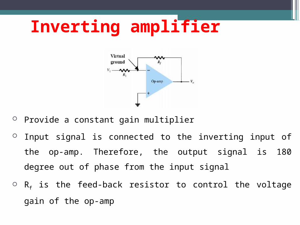
Provide a constant gain multiplier
Input signal is connected to the inverting input of the op-amp. Therefore, the
output signal is 180 degree out of phase from the input signal
Rf is the feed-back resistor to control the voltage gain of the op-amp
Summary of op-amp behavior
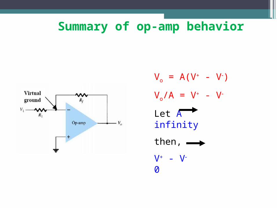
Vo = A(V+ - V)
Vo/A = V+ - V
Let A infinity
then,
V+ - V 0
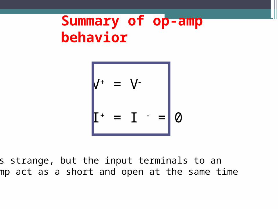
V+ = V
I+ = I = 0
Seems strange, but the input terminals to anop-amp act as a short and open at the same time
Summary of op-amp behavior
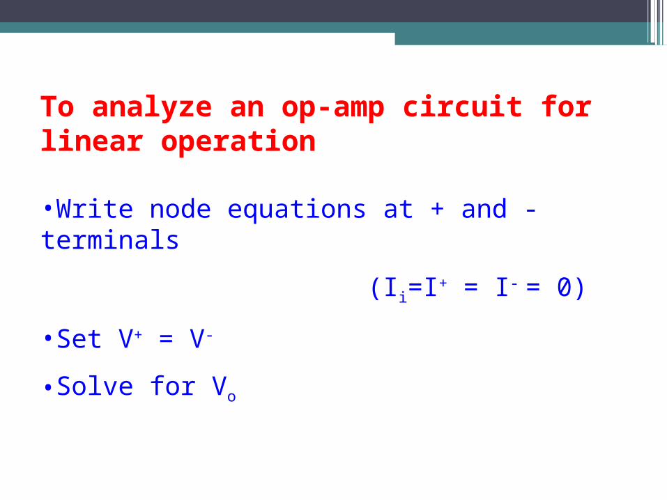
To analyze an op-amp circuit for linear operation
•Write node equations at + and - terminals
(Ii=I+ = I- = 0)
•Set V+ = V-
•Solve for Vo
Inverting amplifier gain
• One of the main features of the inverting amplifier circuit is the
overall gain that it produces.
• This is quite easy to calculate. The voltage gain is actually the
output voltage (Vout) divided by the input voltage (Vin), i.e.
• it is the number of times the output voltage is larger than the input
voltage.
• It is also easy to determine the equation for the voltage gain.
• As the input to the op-amp draws no current this means that the
current flowing in the resistors R1 and R2 is the same
•Using ohms law Vout /R2 = -Vin/R1. Hence the voltage gain
of the circuit Av can be taken as:
•Av = - R2 / R1
•As an example, an amplifier requiring a gain of ten could be
built by making R2 47 k ohms and R1 4.7 k ohms.
Inverting Amplifier Input Impedance
• It is often necessary to know the input impedance of a circuit. A circuit
with a low input impedance may load the output of the previous circuit and
may give rise to effects such as changing the frequency response if the
coupling capacitors are not large.
• It is very simple to determine the input impedance of an inverting
operational amplifier circuit. It is simply the value of the input resistor R1.
This is because the inverting input is at earth potential (i.e. a virtual earth)
and this means that the resistor is connected between the input and earth.
High Input Impedance Inverting Amplifier
• The standard inverting amplifier configuration is widely used with operational
amplifier integrated circuits. It has many advantages: being simple to construct; it
offers the possibility of summation or mixing (in the audio sense) of several
signals; and of course it inverts the signal which can be important in some
instances.
• However the standard inverting amplifier circuit does have some drawbacks which
can be important on some occasions. The main drawback is its input impedance.
To show how this can be important it is necessary to look at the circuit and take
some examples
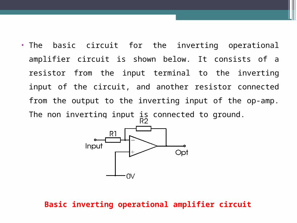
• The basic circuit for the inverting operational amplifier circuit is shown
below. It consists of a resistor from the input terminal to the inverting
input of the circuit, and another resistor connected from the output to the
inverting input of the op-amp. The non inverting input is connected to
ground.
Basic inverting operational amplifier circuit
• The gain for the amplifier can be calculated from the formula:
• Av = - R2 / R1
• If a high gain of, for example 100, is required this means that the ratio of
R2 : R1 is 100. It is good practice to keep the resistors in op amp circuits
within reasonable bounds. In view of this the maximum value for R2
should be 1 M Ohm. This means that the input resistor and hence the input
resistance to the amplifier circuit as a whole is 10 k Ohm. In some
instances this may not be sufficiently high.
• To overcome this problem it is possible to modify the circuit, and add a
couple of extra resistors. The feedback resistor R2 serves to limit the
amount of feedback.
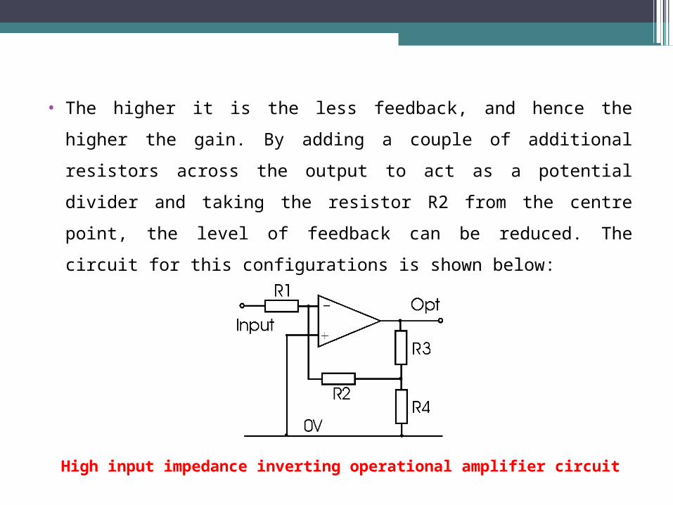
• The higher it is the less feedback, and hence the higher the gain. By adding
a couple of additional resistors across the output to act as a potential
divider and taking the resistor R2 from the centre point, the level of
feedback can be reduced. The circuit for this configurations is shown
below:
High input impedance inverting operational amplifier circuit
• The gain for this amplifier can be calculated from the formula:
• Av = - R2 (R3 + R4) / (R1 x R4 )
• Again the input resistance is equal to R1, but this can be made higher for the same
gain.
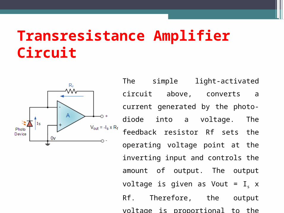
Transresistance Amplifier Circuit
The simple light-activated circuit above,
converts a current generated by the photo-diode
into a voltage. The feedback resistor Rf sets the
operating voltage point at the inverting input
and controls the amount of output. The output
voltage is given as Vout = Is x Rf. Therefore,
the output voltage is proportional to the amount
of input current generated by the photo-diode.
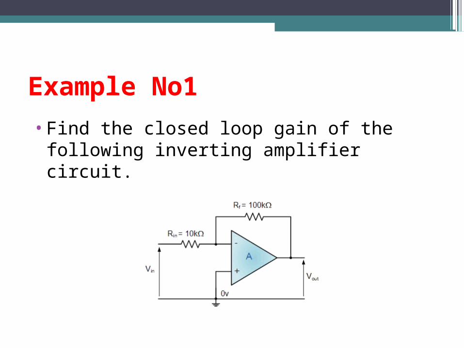
Example No1
•Find the closed loop gain of the following inverting amplifier circuit.
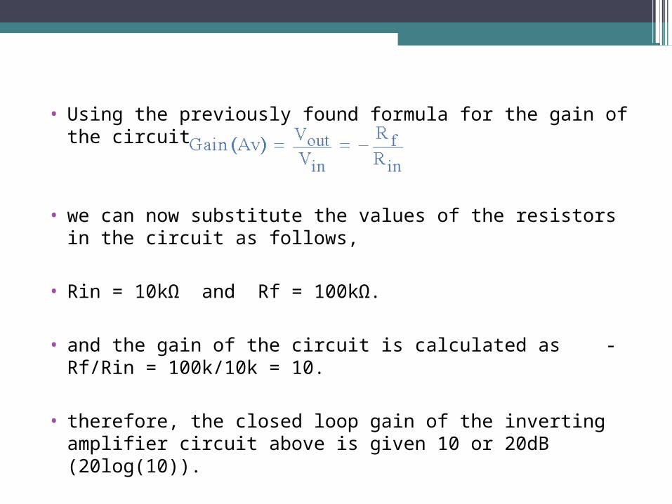
• Using the previously found formula for the gain of the circuit
• we can now substitute the values of the resistors in the circuit as follows,
• Rin = 10kΩ and Rf = 100kΩ.
• and the gain of the circuit is calculated as -Rf/Rin = 100k/10k = 10.
• therefore, the closed loop gain of the inverting amplifier circuit above is given 10 or 20dB (20log(10)).
Example No2
• The gain of the original circuit is to be increased to 40 (32dB), find the new values of the resistors
required.
• Assume that the input resistor is to remain at the same value of 10KΩ, then by re-arranging the
closed loop voltage gain formula we can find the new value required for the feedback resistor Rf.
• Gain = -Rf/Rin
• therefore, Rf = Gain x Rin
• Rf = 40 x 10,000
• Rf = 400,000 or 400KΩ
• The new values of resistors required for the circuit to have a gain of 40 would be,
• Rin = 10KΩ and Rf = 400KΩ.
• The formula could also be rearranged to give a new value of Rin, keeping the same value of Rf.
• One final point to note about the Inverting Amplifier configuration for an operational amplifier, if the two resistors are of equal value, Rin = Rf then the gain of the amplifier will be -1 producing a complementary form of the input voltage at its output as Vout = -Vin. This type of inverting amplifier configuration is generally called a Unity Gain Inverter of simply an Inverting Buffer.

The End
……..Thank you……