Embed Size (px)
Citation preview
Lab #5 Overview
• Activity #1 - Simulation of an Op-Amp inverting amplifier
• Activity #2 - Build and Test the Op-Amp inverting amplifier
• Activity #3 - Determining the Gain and Saturation of the Op-Amp inverting amplifier
Simulation
• Run the simulated circuit found in the class folder (Lab_5_Circuit.msm)
• Notice that a negative voltage is used as the input to produce a positive output voltage
• The gain is the output divided by the input
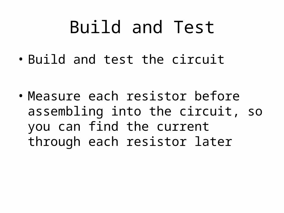
Build and Test
• Build and test the circuit
• Measure each resistor before assembling into the circuit, so you can find the current through each resistor later
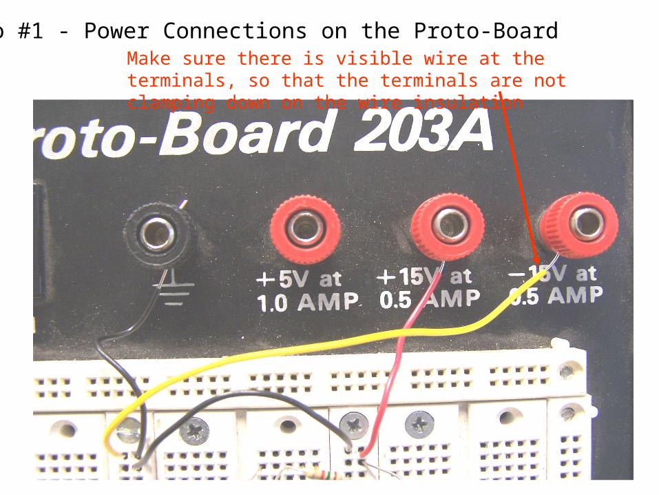
Photo #1 - Power Connections on the Proto-BoardMake sure there is visible wire at the terminals, so that the terminals are not clamping down on the wire insulation
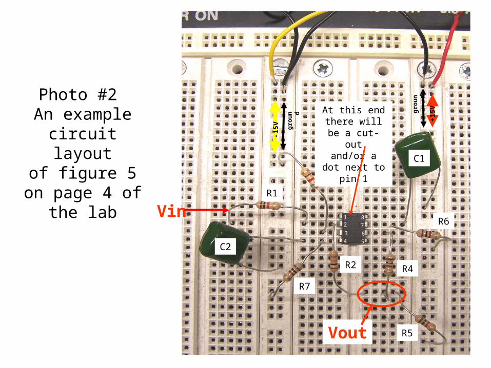
Vout
R1
R5
R4
R3
R2
12
3
4 5
6
8
7
C2
C1
R7
R6
At this end there will be a cut-outand/or a dot next
to pin 1
-15V ground
+15V
ground
Vin
Photo #2 An example circuit layoutof figure 5 on
page 4 of the lab
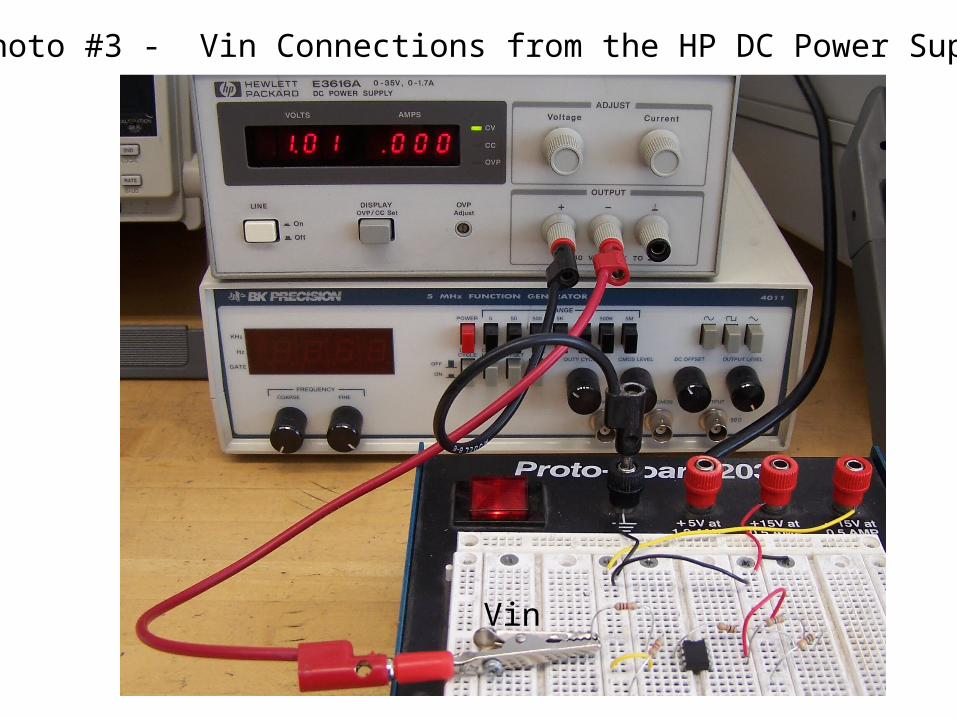
Vin
Photo #3 - Vin Connections from the HP DC Power Supply

Determining Saturation
• Change the input voltage until the output stops going up ( it has reached saturation)
• Switching the leads on the DC power supply enable you to get positive voltages on the inputs (and negative output voltages)