Embed Size (px)
Citation preview
Inc-1
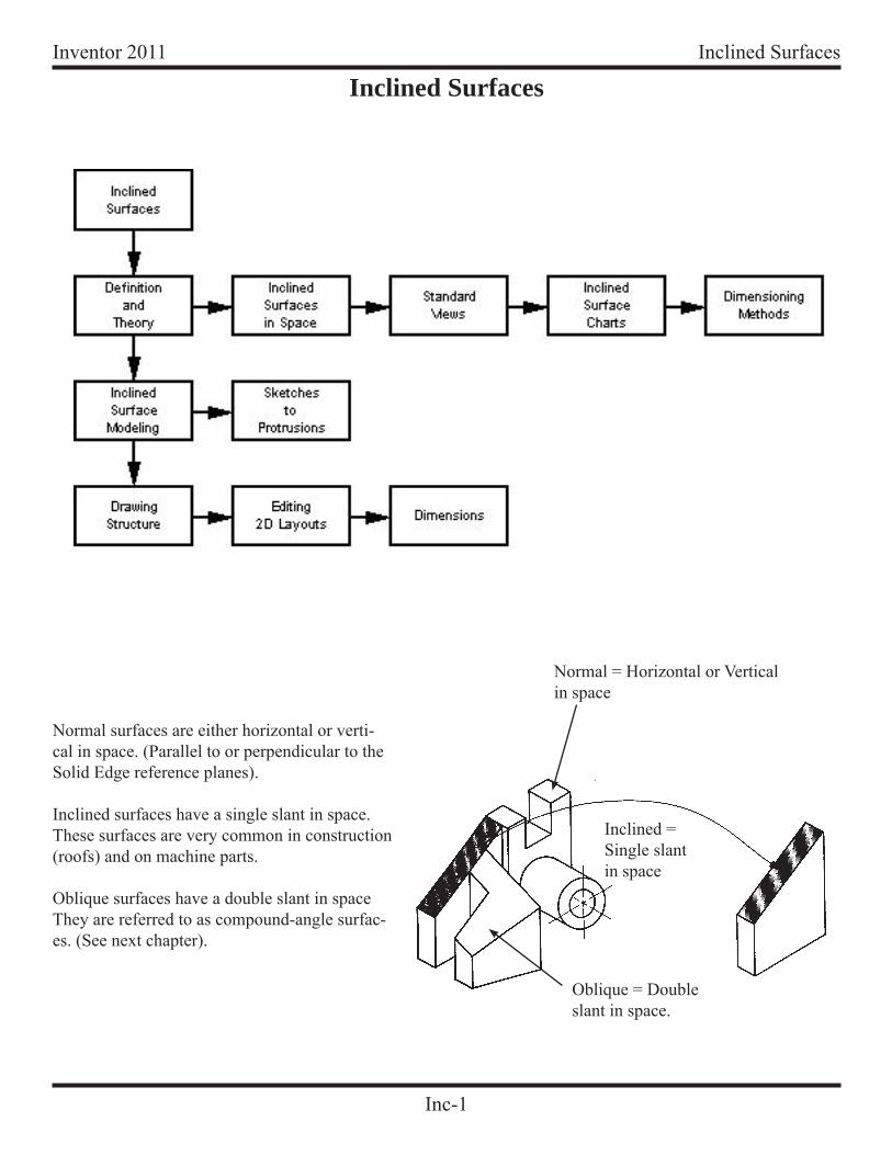
Inventor 2011 Inclined Surfaces
Normal surfaces are either horizontal or verti-cal in space. (Parallel to or perpendicular to the Solid Edge reference planes).
Inclined surfaces have a single slant in space. These surfaces are very common in construction (roofs) and on machine parts.
Oblique surfaces have a double slant in space They are referred to as compound-angle surfac-es. (See next chapter).
Inclined Surfaces
Normal = Horizontal or Vertical in space
Inclined =Single slantin space
Oblique = Doubleslant in space.
Inc-2
Inventor 2011Inclined Surfaces
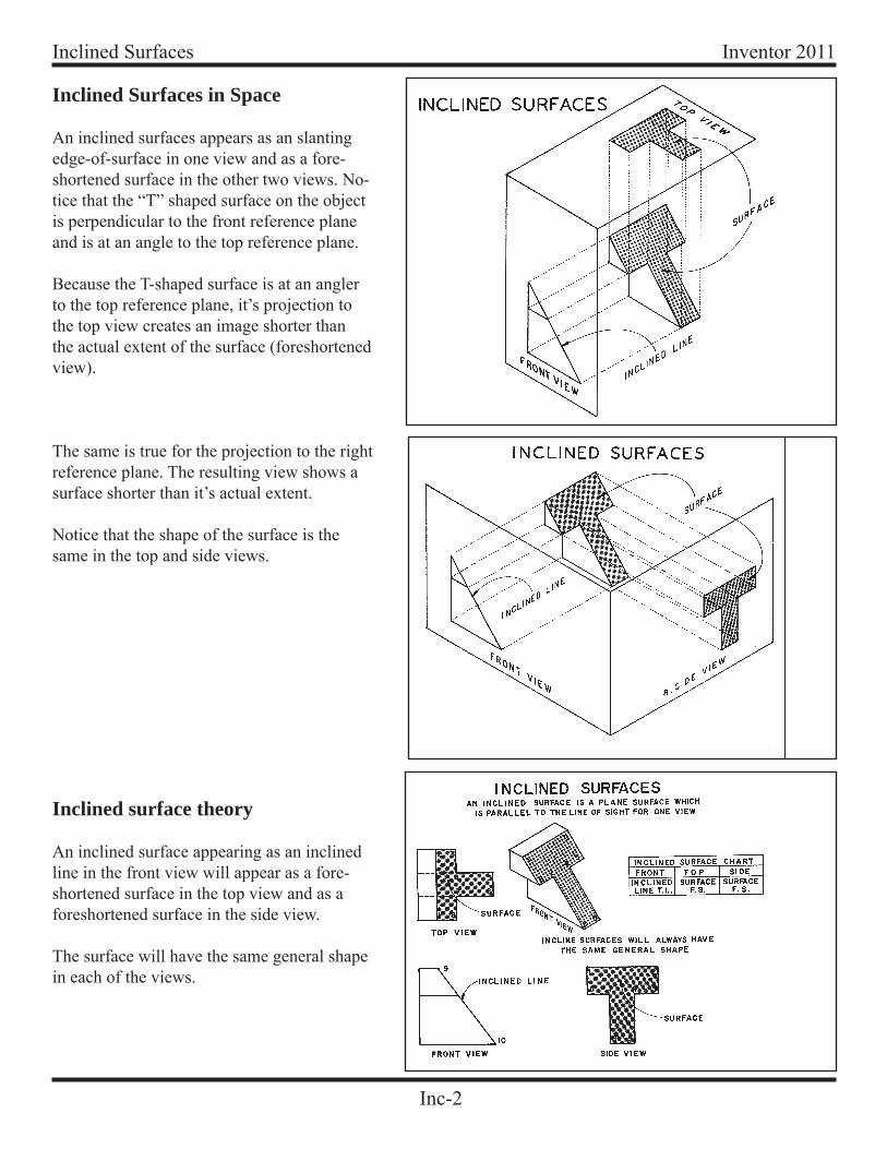
Inclined Surfaces in Space
An inclined surfaces appears as an slanting edge-of-surface in one view and as a fore-shortened surface in the other two views. No-tice that the “T” shaped surface on the object is perpendicular to the front reference plane and is at an angle to the top reference plane.
Because the T-shaped surface is at an angler to the top reference plane, it’s projection to the top view creates an image shorter than the actual extent of the surface (foreshortened view).
The same is true for the projection to the right reference plane. The resulting view shows a surface shorter than it’s actual extent.
Notice that the shape of the surface is the same in the top and side views.
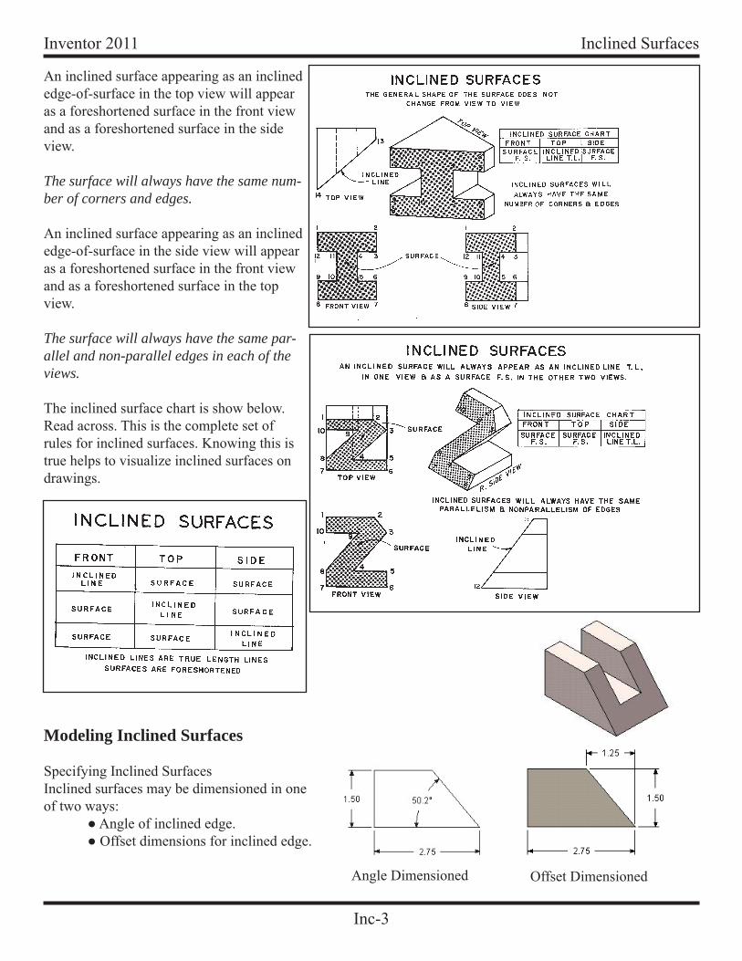
Inclined surface theory
An inclined surface appearing as an inclined line in the front view will appear as a fore-shortened surface in the top view and as a foreshortened surface in the side view.
The surface will have the same general shape in each of the views.
Inc-3
Inventor 2011 Inclined Surfaces
An inclined surface appearing as an inclined edge-of-surface in the top view will appear as a foreshortened surface in the front view and as a foreshortened surface in the side view.
The surface will always have the same num-ber of corners and edges.
An inclined surface appearing as an inclined edge-of-surface in the side view will appear as a foreshortened surface in the front view and as a foreshortened surface in the top view.
The surface will always have the same par-allel and non-parallel edges in each of the views.
The inclined surface chart is show below. Read across. This is the complete set of rules for inclined surfaces. Knowing this is true helps to visualize inclined surfaces on drawings.
Modeling Inclined Surfaces
Specifying Inclined SurfacesInclined surfaces may be dimensioned in one of two ways: ● Angle of inclined edge. ● Offset dimensions for inclined edge.
Angle Dimensioned Offset Dimensioned
Inc-4
Inventor 2011Inclined Surfaces
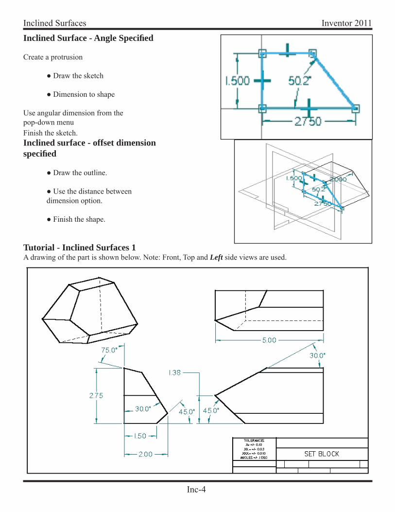
Inclined Surface - Angle Specifi ed
Create a protrusion
● Draw the sketch
● Dimension to shape
Use angular dimension from the pop-down menuFinish the sketch.Inclined surface - offset dimension specifi ed
● Draw the outline.
● Use the distance between dimension option.
● Finish the shape.
Tutorial - Inclined Surfaces 1A drawing of the part is shown below. Note: Front, Top and Left side views are used.
Inc-5
Inventor 2011 Inclined Surfaces
TopPlane
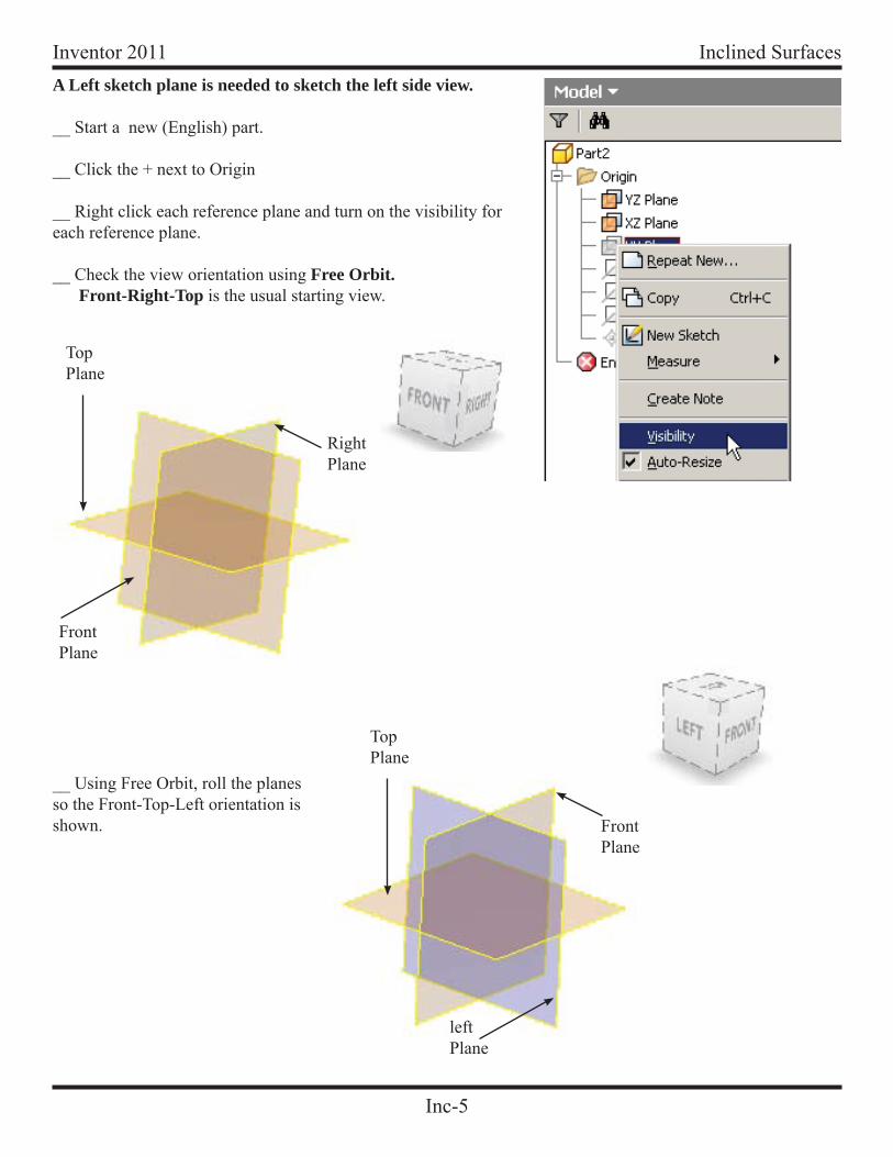
A Left sketch plane is needed to sketch the left side view.
__ Start a new (English) part.
__ Click the + next to Origin
__ Right click each reference plane and turn on the visibility for each reference plane.
__ Check the view orientation using Free Orbit. Front-Right-Top is the usual starting view.
FrontPlane
RightPlane
__ Using Free Orbit, roll the planes so the Front-Top-Left orientation is shown. Front
Plane
TopPlane
leftPlane
Inc-6
Inventor 2011Inclined Surfaces
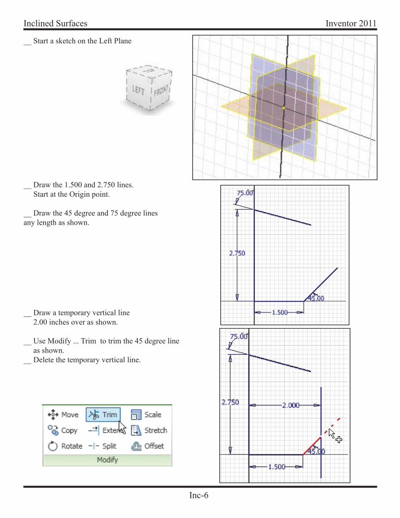
__ Start a sketch on the Left Plane
__ Draw the 1.500 and 2.750 lines. Start at the Origin point.
__ Draw the 45 degree and 75 degree lines any length as shown.
__ Draw a temporary vertical line 2.00 inches over as shown.
__ Use Modify ... Trim to trim the 45 degree line as shown. __ Delete the temporary vertical line.
Inc-7
Inventor 2011 Inclined Surfaces
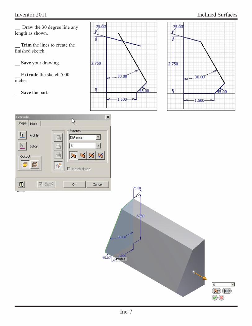
__ Draw the 30 degree line any length as shown.
__ Trim the lines to create the fi nished sketch.
__ Save your drawing.
__ Extrude the sketch 5.00 inches.
__ Save the part.
Inc-8
Inventor 2011Inclined Surfaces
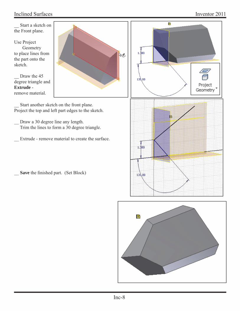
__ Start a sketch on the Front plane.
Use Project Geometryto place lines from the part onto the sketch.
__ Draw the 45 degree triangle and Extrude -remove material.
__ Start another sketch on the front plane.Project the top and left part edges to the sketch.
__ Draw a 30 degree line any length. Trim the lines to form a 30 degree triangle.
__ Extrude - remove material to create the surface.
__ Save the fi nished part. (Set Block)
Inc-9
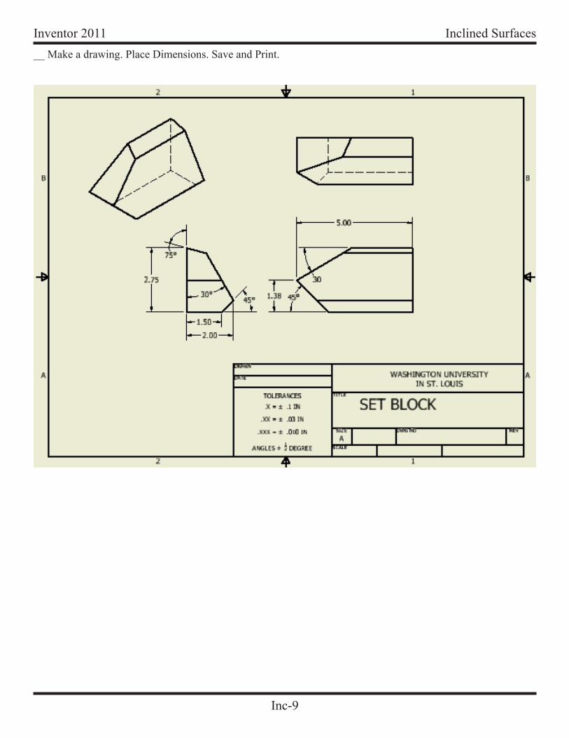
Inventor 2011 Inclined Surfaces__ Make a drawing. Place Dimensions. Save and Print.
Inc-10
Inventor 2011Inclined Surfaces
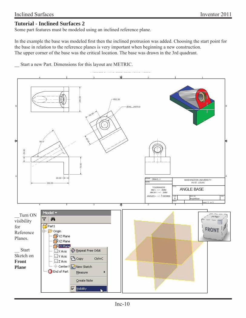
Tutorial - Inclined Surfaces 2Some part features must be modeled using an inclined reference plane.
In the example the base was modeled fi rst then the inclined protrusion was added. Choosing the start point for the base in relation to the reference planes is very important when beginning a new construction.The upper corner of the base was the critical location. The base was drawn in the 3rd quadrant.
__ Start a new Part. Dimensions for this layout are METRIC.PRODUCED BY AN AUTODESK EDUCATIONAL PRODUCT
1
1
2
2
3
3
4
4
A A
B B
DRAWN
TITLE
SIZE
BSCALE
DWG NO
AngleBaseREV
SHEET 1 OF 1
WASHINGTON UNIVERSITYIN ST. LOUISDATE
TOLERANCESMM = +/- .8MM
MM.M = +/- .3MM
ANGLES = +/- 12 DEGREE
150.00
70.0
0
20.0
0
20.00
60.0°
R32.50
26 40 10
100.
00
40.00
50.00
ANGLE BASE
CRAIG, J
__Turn ON visibilityforReferencePlanes.
__ StartSketch on FrontPlane
Inc-11
Inventor 2011 Inclined Surfaces
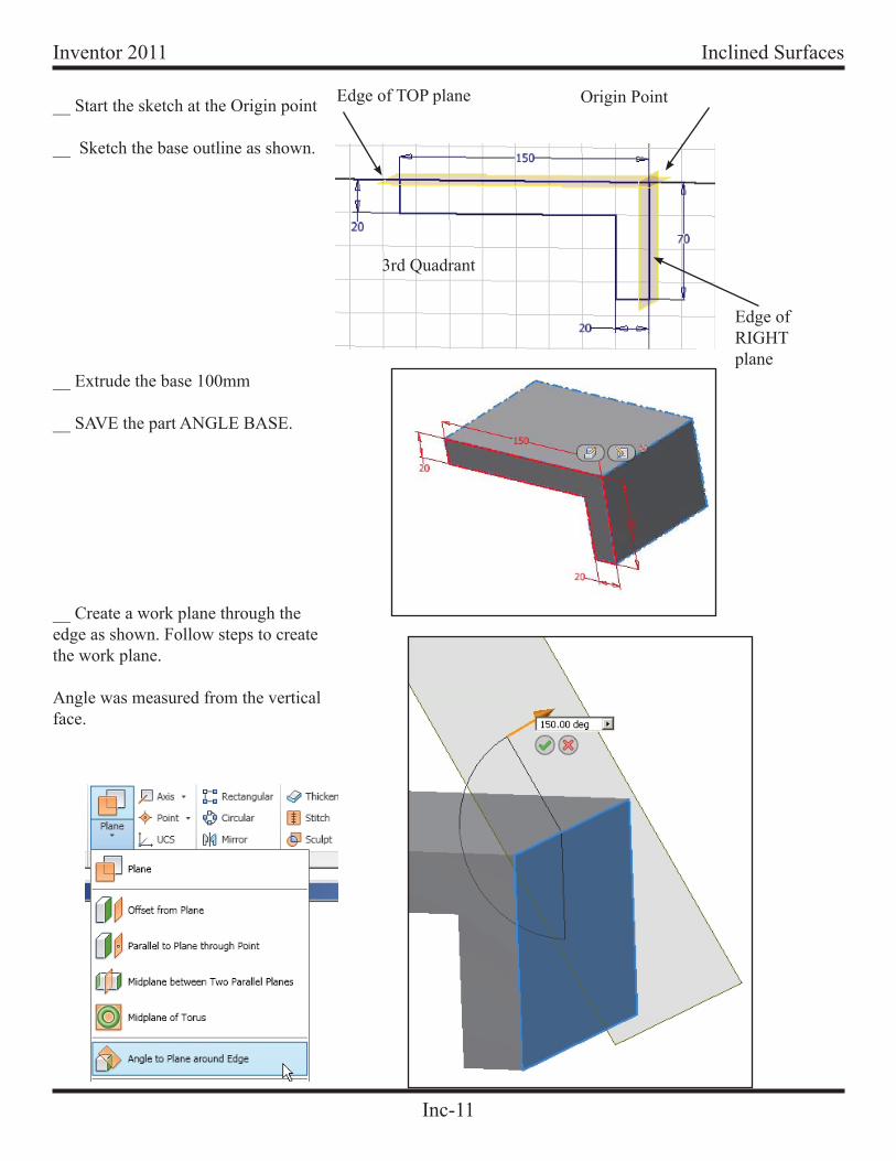
3rd Quadrant
Origin Point__ Start the sketch at the Origin point
__ Sketch the base outline as shown.
Edge of TOP plane
Edge ofRIGHTplane
__ Extrude the base 100mm
__ SAVE the part ANGLE BASE.
__ Create a work plane through the edge as shown. Follow steps to create the work plane.
Angle was measured from the vertical face.
Inc-12
Inventor 2011Inclined Surfaces
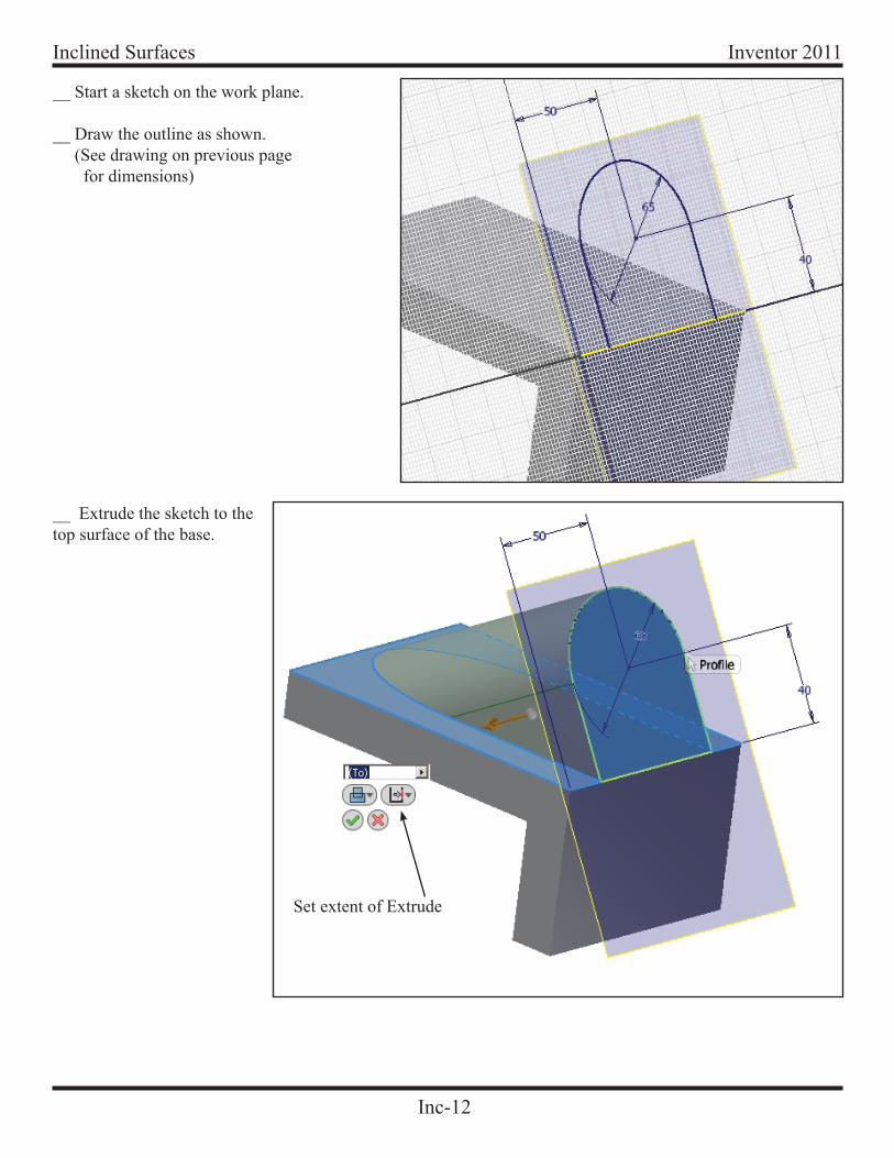
__ Start a sketch on the work plane.
__ Draw the outline as shown. (See drawing on previous page for dimensions)
__ Extrude the sketch to the top surface of the base.
Set extent of Extrude
Inc-13
Inventor 2011 Inclined Surfaces
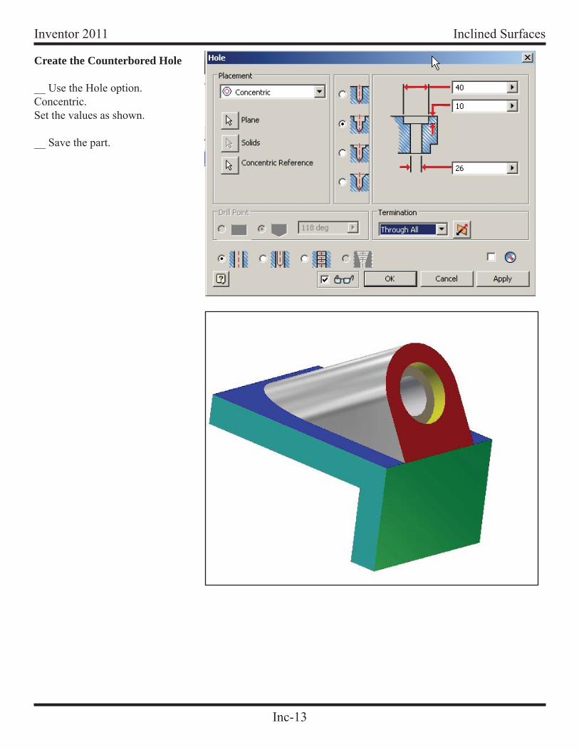
Create the Counterbored Hole
__ Use the Hole option.Concentric.Set the values as shown.
__ Save the part.
Inc-14
Inventor 2011Inclined Surfaces
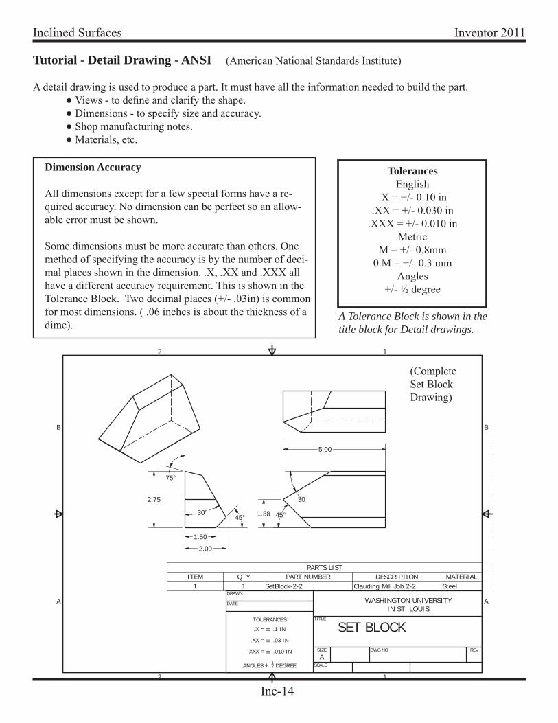
Tutorial - Detail Drawing - ANSI (American National Standards Institute)
A detail drawing is used to produce a part. It must have all the information needed to build the part. ● Views - to defi ne and clarify the shape. ● Dimensions - to specify size and accuracy. ● Shop manufacturing notes. ● Materials, etc.
Dimension Accuracy
All dimensions except for a few special forms have a re-quired accuracy. No dimension can be perfect so an allow-able error must be shown.
Some dimensions must be more accurate than others. One method of specifying the accuracy is by the number of deci-mal places shown in the dimension. .X, .XX and .XXX all have a different accuracy requirement. This is shown in the Tolerance Block. Two decimal places (+/- .03in) is common for most dimensions. ( .06 inches is about the thickness of a dime).
TolerancesEnglish
.X = +/- 0.10 in.XX = +/- 0.030 in
.XXX = +/- 0.010 inMetric
M = +/- 0.8mm0.M = +/- 0.3 mm
Angles+/- ½ degree
A Tolerance Block is shown in the title block for Detail drawings.
PR
OD
UC
ED
BY
AN
AUTO
DE
SKE
DU
CA
TION
ALP
RO
DU
CT
1
1
2
2
A A
B B
DRAWN
DATE
TITLE
SIZE
ASCALE
DWG NO REV
WASHINGTON UNIVERSITYIN ST. LOUIS
TOLERANCES
.X = .1 IN
.XX = .03 IN
.XXX = .010 IN
ANGLES 12 DEGREE
PARTS LISTMATERIALDESCRIPTIONPART NUMBERQTYITEM
SteelClauding Mill Job 2-2SetBlock-2-211
2.00
45°30°
75°
2.75
1.50
1.38 45°
30
5.00
SET BLOCK
(CompleteSet BlockDrawing)
Inc-15
Inventor 2011 Inclined Surfaces
1
1
2
2
3
3
4
4
A A
B B
DRAWN
TITLE
SIZE
BSCALE
DWG NO
AngleBaseREV
SHEET 1 OF 1
WASHINGTON UNIVERSITYIN ST. LOUISDATE
TOLERANCESMM = +/- .8MM
MM.M = +/- .3MM
ANGLES = +/- 12 DEGREE
150.00
70.0
0
20.0
0
20.00
60.0°
R32.50
26 40 10
100.
00
40.00
50.00
ANGLE BASE
CRAIG, J
1
1
2
2
3
3
4
4
A A
B B
DRAWN
TITLE
SIZE
BSCALE
DWG NO REV
SHEET 1 OF 1
WASHINGTON UNIVERSITYIN ST. LOUISDATE
TOLERANCESMM = +/- .8MM
MM.M = +/- .3MM
ANGLES = +/- 12 DEGREE
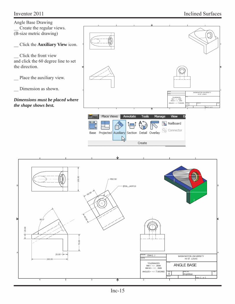
Angle Base Drawing__ Create the regular views.(B-size metric drawing)
__ Click the Auxiliary View icon.
__ Click the front viewand click the 60 degree line to set the direction.
__ Place the auxiliary view.
__ Dimension as shown.
Dimensions must be placed where the shape shows best.
Inc-16
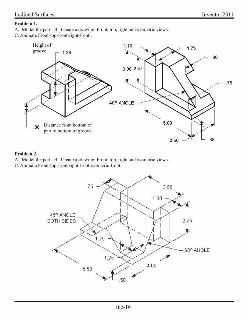
Inventor 2011Inclined SurfacesProblem 1. A. Model the part. B. Create a drawing. Front, top, right and isometric views.C. Animate Front-top-front-right-front .
Distance from bottom of part to bottom of groove.
Height ofgroove
Problem 2. A. Model the part. B. Create a drawing. Front, top, right and isometric views.C. Animate Front-top-front-right-front-isometric-front.
Inc-17
Inventor 2011 Inclined Surfaces