Embed Size (px)
Citation preview

Invacare® FDX® PowerWheelchair Base
en FDX, FDX-CG, FDX-MCGUser Manual
This manual MUST be given to the user of the product.BEFORE using this product, read this manual and save for future reference.

©2015 Invacare®CorporationAll rights reserved. Republication, duplication or modification in whole or in part is prohibited withoutprior written permission from Invacare. Trademarks are identified by ™and ®. All trademarks areowned by or licensed to Invacare Corporation or its subsidiaries unless otherwise noted.

Contents
1 General . . . . . . . . . . . . . . . . . . . . . . . . . . . . . . . . . . . . . . . . 51.1 Symbols . . . . . . . . . . . . . . . . . . . . . . . . . . . . . . . . . . . . . 51.2 Reference Documents . . . . . . . . . . . . . . . . . . . . . . . . . . . 51.3 General Guidelines . . . . . . . . . . . . . . . . . . . . . . . . . . . . . 51.3.1 Set Up . . . . . . . . . . . . . . . . . . . . . . . . . . . . . . . . . . . . 71.3.2 Transport - Wheelchair Tie-Down Restraints and
Seat Restraints (TRRO or TRBKTS) . . . . . . . . . . . . . . 81.3.3 Stairways and Escalators . . . . . . . . . . . . . . . . . . . . . . . 101.3.4 Repair and Service Information — Dealers and/or
Qualified Technicians. . . . . . . . . . . . . . . . . . . . . . . . . 111.3.5 Wear and Tear Information. . . . . . . . . . . . . . . . . . . . . 121.3.6 Global Limited Warranty (Excluding Canada) . . . . . . . . 121.3.7 Canada Limited Warranty . . . . . . . . . . . . . . . . . . . . . . 13
2 Safety Handling . . . . . . . . . . . . . . . . . . . . . . . . . . . . . . . . . . 152.1 Safety/Handling . . . . . . . . . . . . . . . . . . . . . . . . . . . . . . . . 152.1.1 A Note to Wheelchair Assistants. . . . . . . . . . . . . . . . . 162.1.2 Stability and Balance . . . . . . . . . . . . . . . . . . . . . . . . . . 172.1.3 Driving Surfaces . . . . . . . . . . . . . . . . . . . . . . . . . . . . . 182.1.4 Coping with Everyday Obstacles . . . . . . . . . . . . . . . . . 182.1.5 Negotiating Inclines. . . . . . . . . . . . . . . . . . . . . . . . . . . 192.1.6 Footplates and Front Rigging . . . . . . . . . . . . . . . . . . . . 212.1.7 Reaching, Leaning and Bending - Forward . . . . . . . . . . . 212.1.8 Reaching, Bending - Backward . . . . . . . . . . . . . . . . . . . 222.1.9 Transferring To and From Other Seats . . . . . . . . . . . . 222.1.10 Storage . . . . . . . . . . . . . . . . . . . . . . . . . . . . . . . . . . 232.1.11 Electrical - Grounding Instructions . . . . . . . . . . . . . . . 242.1.12 Electrical - Batteries . . . . . . . . . . . . . . . . . . . . . . . . . 242.1.13 Electrical - Charging Batteries . . . . . . . . . . . . . . . . . . 252.1.14 Recycling Batteries . . . . . . . . . . . . . . . . . . . . . . . . . . 262.1.15 Weight Training . . . . . . . . . . . . . . . . . . . . . . . . . . . . 26
2.1.16 Weight Capacity . . . . . . . . . . . . . . . . . . . . . . . . . . . . 262.1.17 Electromagnetic Interference (EMI) From Radio
Wave Sources . . . . . . . . . . . . . . . . . . . . . . . . . . . . . 262.1.18 Powered Wheelchair Electromagnetic Interference
(EMI) . . . . . . . . . . . . . . . . . . . . . . . . . . . . . . . . . . . . 27
3 Label Locations . . . . . . . . . . . . . . . . . . . . . . . . . . . . . . . . . . 293.1 Label Locations . . . . . . . . . . . . . . . . . . . . . . . . . . . . . . . . 29
4 Technical Data . . . . . . . . . . . . . . . . . . . . . . . . . . . . . . . . . . 354.1 Specifications . . . . . . . . . . . . . . . . . . . . . . . . . . . . . . . . . . 354.1.1 Models. . . . . . . . . . . . . . . . . . . . . . . . . . . . . . . . . . . . 354.1.2 Overall Dimensions . . . . . . . . . . . . . . . . . . . . . . . . . . 354.1.3 Seat . . . . . . . . . . . . . . . . . . . . . . . . . . . . . . . . . . . . . . 354.1.4 Wheels . . . . . . . . . . . . . . . . . . . . . . . . . . . . . . . . . . . 354.1.5 Driving. . . . . . . . . . . . . . . . . . . . . . . . . . . . . . . . . . . . 364.1.6 Maximum Weight Capacity . . . . . . . . . . . . . . . . . . . . . 36
5 Wheelchair Operation . . . . . . . . . . . . . . . . . . . . . . . . . . . . 375.1 Preparing the Joystick for Use. . . . . . . . . . . . . . . . . . . . . . 375.2 Turning the Power On/Off . . . . . . . . . . . . . . . . . . . . . . . . 385.3 Using the Joystick to Drive the Wheelchair . . . . . . . . . . . . 385.4 SPJ+™, MK6i™ SPJ+ w/PSS and MK6i SPJ+ w/ACC
Joystick Switches and Indicators . . . . . . . . . . . . . . . . . . . 395.4.1 On/Off Button . . . . . . . . . . . . . . . . . . . . . . . . . . . . . . 395.4.2 Speedometer . . . . . . . . . . . . . . . . . . . . . . . . . . . . . . . 395.4.3 Speed Control Buttons . . . . . . . . . . . . . . . . . . . . . . . 405.4.4 Joystick . . . . . . . . . . . . . . . . . . . . . . . . . . . . . . . . . . . 405.4.5 Charger/Programming Input . . . . . . . . . . . . . . . . . . . . 405.4.6 Information Gauge Display . . . . . . . . . . . . . . . . . . . . . 405.4.7 Service Indicator. . . . . . . . . . . . . . . . . . . . . . . . . . . . . 405.4.8 Mode Button . . . . . . . . . . . . . . . . . . . . . . . . . . . . . . . 41
5.5 CMPJ+ Joystick, Switches and Indicators . . . . . . . . . . . . . . 415.5.1 On/Off - Drive Select Toggle Switch . . . . . . . . . . . . . . 415.5.2 Speed Control . . . . . . . . . . . . . . . . . . . . . . . . . . . . . . 41

5.5.3 Joystick . . . . . . . . . . . . . . . . . . . . . . . . . . . . . . . . . . . 415.5.4 Charger/Programming Input . . . . . . . . . . . . . . . . . . . . 415.5.5 LCD Display Screens . . . . . . . . . . . . . . . . . . . . . . . . . 425.5.6 User Settings . . . . . . . . . . . . . . . . . . . . . . . . . . . . . . . 445.5.7 Programmable Mono Ports 1 and 2 with External
Mode Switch. . . . . . . . . . . . . . . . . . . . . . . . . . . . . . . 465.5.8 Remote On/Off Switch . . . . . . . . . . . . . . . . . . . . . . . . 465.5.9 Mode Switch . . . . . . . . . . . . . . . . . . . . . . . . . . . . . . . 465.5.10 Memory Card Slot . . . . . . . . . . . . . . . . . . . . . . . . . . 46
5.6 When to Charge Batteries . . . . . . . . . . . . . . . . . . . . . . . . 475.6.1 SPJ+, SPJ+ w/PSS and SPJ+ w/ACC Joysticks . . . . . . . . . 475.6.2 CMPJ+ Joystick . . . . . . . . . . . . . . . . . . . . . . . . . . . . . . 47
5.7 Charging Batteries . . . . . . . . . . . . . . . . . . . . . . . . . . . . . . 485.7.1 Description and Use of Battery Chargers . . . . . . . . . . . 48
5.8 Running Lights . . . . . . . . . . . . . . . . . . . . . . . . . . . . . . . . . 495.8.1 Running Lights Through CMPJ+ Joystick . . . . . . . . . . . . 505.8.2 Running Lights Through Single Function Switch . . . . . . . 50
5.9 Disengaging/Engaging Motor Lock Levers. . . . . . . . . . . . . . 505.10 Operating the Wheel Locks . . . . . . . . . . . . . . . . . . . . . . 50
6 TransportReadyOption(TRRO). . . . . . . . . . . . . . . . . . . . . 526.1 About Transport Ready Packages . . . . . . . . . . . . . . . . . . . 526.2 Compliance Information . . . . . . . . . . . . . . . . . . . . . . . . . . 536.3 Specifications . . . . . . . . . . . . . . . . . . . . . . . . . . . . . . . . . . 536.4 Positioning the Wheelchair in the Vehicle . . . . . . . . . . . . . 546.5 Securement Points . . . . . . . . . . . . . . . . . . . . . . . . . . . . . . 546.6 Securing the Wheelchair . . . . . . . . . . . . . . . . . . . . . . . . . 546.7 Securing the Occupant . . . . . . . . . . . . . . . . . . . . . . . . . . . 556.7.1 Wheelchair-Anchored Belts . . . . . . . . . . . . . . . . . . . . 556.7.2 Vehicle-Anchored Belts . . . . . . . . . . . . . . . . . . . . . . . . 566.7.3 Seating System . . . . . . . . . . . . . . . . . . . . . . . . . . . . . . 566.7.4 Positioning Belts . . . . . . . . . . . . . . . . . . . . . . . . . . . . . 56
7 Set Up Maintenance . . . . . . . . . . . . . . . . . . . . . . . . . . . . . . 587.1 Setup/Delivery Inspection . . . . . . . . . . . . . . . . . . . . . . . . . 58
7.2 User/Attendant Inspection Checklists . . . . . . . . . . . . . . . . 587.2.1 Inspect/Adjust Weekly . . . . . . . . . . . . . . . . . . . . . . . . 587.2.2 Inspect/Adjust Monthly . . . . . . . . . . . . . . . . . . . . . . . . 587.2.3 Inspect/Adjust Periodically. . . . . . . . . . . . . . . . . . . . . . 59
7.3 Service Inspection . . . . . . . . . . . . . . . . . . . . . . . . . . . . . . 597.3.1 Six Month Inspection . . . . . . . . . . . . . . . . . . . . . . . . . 597.3.2 Inspect/Adjust Every 18 Months. . . . . . . . . . . . . . . . . . 607.3.3 Inspect/Adjust Every 2 Years . . . . . . . . . . . . . . . . . . . . 60
7.4 Batteries . . . . . . . . . . . . . . . . . . . . . . . . . . . . . . . . . . . . . 607.5 Using the Proper Batteries . . . . . . . . . . . . . . . . . . . . . . . . 617.6 Removing/Installing the Batteries. . . . . . . . . . . . . . . . . . . . 617.6.1 Removing/Installing the Front Battery. . . . . . . . . . . . . . 617.6.2 Removing/Installing the Rear Battery . . . . . . . . . . . . . . 62
7.7 Replacing the Batteries and/or Battery Cables . . . . . . . . . . 637.7.1 Disconnecting Battery Cables . . . . . . . . . . . . . . . . . . . 637.7.2 Connecting Battery Cables . . . . . . . . . . . . . . . . . . . . . 64
7.8 Anti-Tippers . . . . . . . . . . . . . . . . . . . . . . . . . . . . . . . . . . 657.9 Adjusting Forks . . . . . . . . . . . . . . . . . . . . . . . . . . . . . . . . 657.10 Repositioning Joystick. . . . . . . . . . . . . . . . . . . . . . . . . . . 667.11 Disconnecting/Connecting the SPJ+ Joysticks . . . . . . . . . . 677.11.1 Disconnecting the SPJ+ Joysticks . . . . . . . . . . . . . . . . 677.11.2 Connecting the SPJ+ Joysticks . . . . . . . . . . . . . . . . . . 67
7.12 Disconnecting/Connecting the CMPJ+ Joysticks . . . . . . . . 677.12.1 Connecting the CMPJ+ Joysticks . . . . . . . . . . . . . . . . 677.12.2 Disconnecting the CMPJ+ Joysticks . . . . . . . . . . . . . . 68
8 Troubleshooting . . . . . . . . . . . . . . . . . . . . . . . . . . . . . . . . . 698.1 Driving Performance . . . . . . . . . . . . . . . . . . . . . . . . . . . . 698.2 Electrical . . . . . . . . . . . . . . . . . . . . . . . . . . . . . . . . . . . . . 698.2.1 SPJ+, SPJ+ w/PSS or SPJ+ w/ACC Joysticks . . . . . . . . . . 698.2.2 CMPJ+, PSR+, PSF+ Joysticks or Displays . . . . . . . . . . . 71
8.3 Checking Battery Charge Level . . . . . . . . . . . . . . . . . . . . . 74

General
1 General
1.1 SymbolsSignal symbols and/or words are used in this manual and apply tohazards or unsafe practices which could result in personal injury orproperty damage. See the information below for definitions of thesignal words.
DANGER!– Danger indicates a imminently hazardous situationwhich, if not avoided, could result in death or seriousinjury.
WARNING!– Warning indicates a potentially hazardous situationwhich, if not avoided, could result in death or seriousinjury.
CAUTION!– Caution indicates a potentially hazardous situationwhich, if not avoided, may result in property damageor minor injury or both.
IMPORTANT– Indicates a hazardous situation that could result indamage to property if it is not avoided.
Gives useful tips, recommendations and information forefficient, trouble-free use.
1.2 Reference DocumentsRefer to the table below for part numbers of additionaldocuments which are referenced in this manual.
MANUAL PART NUMBER
MK6i™ ElectronicsProgramming Guide
1141471
Adjustable ASBA Owner’sManual
1143192
Van Seat Owner’s Manual 1143195
Formula™ CG Seating System 1143155
Adjustable ASBA Service Manual 1143238
1.3 General GuidelinesThe safety section contains important information for the safeoperation and use of this product.
DANGER!Risk of Death, Injury or DamageImproper use of this product may cause injury or damage– If you are unable to understand the warnings, cautionsor instructions, contact a health care professional ordealer before attempting to use this equipment.
– DO NOT use this product or any available optionalequipment without first completely reading andunderstanding these instructions and any additionalinstructional material such as user manual, servicemanuals or instruction sheets supplied with thisproduct or optional equipment.
1163181-F~00 5

Invacare® FDX® Power Wheelchair Base
DANGER!Risk of Death, Serious Injury, or DamageIncorrect repair and/or servicing of this wheelchairperformed by users/caregivers or unqualified technicianscan result in death, serious injury, or damage.– Users/Caregivers — DO NOT attempt to repairand/or service this wheelchair.
– Repair and/or service of this wheelchair MUST beperformed by a qualified technician. Contact a dealeror Invacare technician.
WARNING!– DO NOT connect any medical devices such asventilators, life support machines, etc. directly tothe batteries used to power the wheelchair. Thiscould cause unexpected failure of the device and thewheelchair.
WARNING!Risk of Serious Injury or DamageUse of non-Invacare accessories may result in seriousinjury or damage.– Invacare products are specifically designed andmanufactured for use in conjunction with Invacareaccessories. Accessories designed by othermanufacturers have not been tested by Invacare andare not recommended for use with Invacare products.
– DO NOT use non-Invacare accessories.– To obtain Invacare accessories, contact Invacare byphone or at www.invacare.com
DANGER!Risk of Death, Serious Injury, or DamageUse of incorrect or improper replacement (service)parts may cause death, serious injury, or damage.– Replacement parts MUST match original Invacareparts.
– ALWAYS provide the wheelchair serial number toassist in ordering the correct replacement parts.
WARNING!Risk of Serious Injury or DamageAttaching hardware that is loosely secured could causeloss of stability resulting in serious injury or damage.– After ANY adjustments, repair or service and beforeuse, make sure that all attaching hardware is tightenedsecurely.
DANGER!Risk of Death, Serious Injury, or DamageMissing attaching hardware could cause instabilityresulting in death, serious injury or damage.– Ensure all attaching hardware is present and tightenedsecurely
WARNING!Risk of Serious Injury or DamageLoss of power due to loose electrical connectionscould cause the wheelchair to suddenly stop resulting inserious injury or damage.– ALWAYS ensure that all electrical connections aretightly connected so they don’t vibrate loose.
6 1163181-F~00

General
THE INFORMATION CONTAINED IN THIS DOCUMENTIS SUBJECT TO CHANGE WITHOUT NOTICE.
Check all parts for shipping damage and test before using.In case of damage, DO NOT use. Contact Invacare/Carrierfor further instruction
As a manufacturer of wheelchairs, Invacare endeavors tosupply a wide variety of wheelchairs to meet many needsof the end user. However, final selection of the type ofwheelchair to be used by an individual rests solely withthe user and his/her healthcare professional capable ofmaking such a selection. Invacare recommends workingwith a qualified rehab technology provider, such as an ATP,(Assisstive Technology Professional).
1.3.1 Set Up
WARNING!Risk of Injury or DamageIncorrect set up of this wheelchair performed byusers/caregivers or unqualified technicians can result ininjury or damage.– User/Caregivers- DO NOT attempt to set up thiswheelchair.
– Initial set up of this wheelchair MUST be performedby a qualified technician.
DANGER!Risk of Death, Serious Injury, or DamageContinued use of the wheelchair that is not set to thecorrect specifications may cause erratic behavior of thewheelchair resulting in death, serious injury, or damage.– Performance adjustments should only be made byprofessionals of the healthcare field or personsfully conversant with this process and the driver'scapabilities.
– After the wheelchair has been set up/adjusted, checkto make sure that the wheelchair performs to thespecifications entered during the set up procedure. Ifthe wheelchair does not perform to specifications,turn the wheelchair Off immediately and reenter setup specifications. Contact Invacare, if wheelchair stilldoes not perform to correct specifications.
WARNING!Risk of Serious Injury or DamageMoving the seating system from the factory setting mayreduce driver control, wheelchair stability, tractionand increase caster wear resulting in serious injury ordamage.– Move the seating system ONLY when necessary to fitthe wheelchair to the user.
– If the seating system must be moved, ALWAYS inspectthe wheelchair to ensure the front rigging DOES NOTinterfere with the front casters.
– If the seating system must be moved, ALWAYSinspect to ensure the wheelchair DOES NOT easilytip forward or backward.
1163181-F~00 7

Invacare® FDX® Power Wheelchair Base
DANGER!Risk of Death, Serious Injury or DamageOperating the wheelchairs outdoor or in areas of poorlighting may result in death, serious injury, or damage.Operating the wheelchair near motor vehicles may resultin death, serious injury or damage.– DO NOT operate on roads, streets or highways.– Use caution when operating the wheelchair outdoorsat night or in areas with poor lighting.
– ALWAYS be aware of motor vehicles when using thewheelchair.
WARNING!Risk of Minor to Serious InjuryPinch points can cause minor to serious injury.– Be mindful of potential pinch points and use cautionwhen using this product.
WARNING!Risk of Serious InjuryImpacting objects in the surrounding environment cancause serious injury.– When maneuvering the wheelchair around, ALWAYShave assured cleared distance with all objects inenvironment.
WARNING!Risk of Serious InjurySharp edges can cause serious injury.– Be mindful that some parts may have sharp edges. Usecaution when encountering these sharp edges.
WARNING!Risk of Serious InjuryHot surfaces can cause severe burns.– Be mindful of potential hot surfaces and avoid touching.
DANGER!Risk of Death, Serious Injury, or DamageLighted cigarettes dropped onto an upholstered seatingsystem can cause a fire resulting in death, serious injury,or damage.Wheelchair occupants are at particular risk of deathor serious injury from these fires and resulting fumesbecause they may not have the ability to move awayfrom the wheelchair.– DO NOT smoke while using this wheelchair.
1.3.2 Transport - Wheelchair Tie-Down Restraintsand Seat Restraints (TRRO or TRBKTS)
WARNING!Risk of Death, Serious Injury, or PropertyDamageFailure to observe the following transport warnings mayresult in death, serious injury, or property damage.
8 1163181-F~00

General
WARNING!– Only use the transport brackets included with TRROor TRBKTS for the purposes described in this manual.
– TRRO (Transport Ready Option) - TRRO includesfour factory-installed transport brackets and awheelchair anchored pelvic belt. TRRO has beencrash-tested in accordance with ANSI/RESNA WCVol 1 Section 19 Frontal Impact Test requirements forwheelchairs with a 130 lb (59 kg) crash test dummy,which corresponds to a person with a weight of 125lbs (57 kg) to 165 lbs (75 kg) for Junior seat sizes ora 168 lb (76 kg) crash dummy, which corresponds toa person with a weight of 165 lbs (75 kg) to 300 lbs(136 kg) for Adult seat sizes.
– TRBKTS (Wheelchair Transport Brackets) - TRBKTSincludes four factory-installed wheelchair transportbrackets. TRBKTS has not been crash-tested inaccordance with WC 19. Use these transportbrackets only to secure an unoccupied wheelchairduring transport.
WARNING!– As of this date, the Department of Transportation hasnot approved any tie-down systems for transportationof a user while in a wheelchair, in a moving vehicleof any type. It is Invacare’s position that users ofwheelchairs should be transferred into appropriateseating in vehicles for transportation and use bemade of the restraints made available by the autoindustry. Invacare cannot and does not recommendany wheelchair transportation systems.
– Battery support brackets MUST be installed at alltimes. Otherwise, the wheelchair will not be WC/19compliant. Refer to the Transport section in the baseuser manual that was shipped with the product formore information about transporting the wheelchair.
1163181-F~00 9

Invacare® FDX® Power Wheelchair Base
1.3.3 Stairways and Escalators
WARNING!– DO NOT attempt to move an occupied powerwheelchair between floors using a stairway. Use anelevator to move an occupied power wheelchairbetween floors.
– If moving a power wheelchair between floors by meansof a stairway, the occupant MUST be removed andtransported independently of the power wheelchair.
– Extreme caution is advised when it is necessary tomove an unoccupied power wheelchair up or downthe stairs. Invacare recommends using two assistantsand making thorough preparations. Make sure to useONLY secure, non-detachable parts for hand-holdsupports.
– DO NOT use an escalator to move a wheelchairbetween floors. Serious bodily injury may occur.
– DO NOT attempt to lift the wheelchair by anyremovable (detachable) parts. Lifting by means ofany removable (detachable) parts of a wheelchairmay result in injury to the user or damage to thewheelchair.
– The weight of the wheelchair varies depending on themodel. Refer to the Technical Data section of thismanual for the weight of the wheelchair. ALWAYSuse proper lifting techniques (lift with your legs) toavoid injury.
Follow this procedure for moving the wheelchair between floorswhen an elevator is NOT available:
When using a stairway to move the wheelchair and anyaccessories, move all wheelchair components away from thestairway prior to reassembly.
1. Remove the occupant from the wheelchair.2. Remove the batteries from wheelchair. Refer to Battery
Removal.3. Bend your knees and keep your back straight.4. Using non-removable (non-detachable) parts of the wheelchair,
lift the wheelchair off of the ground and transfer the wheelchairup or down the stairs.
5. The wheelchair should not be lowered until the last stair hasbeen negotiated and the wheelchair has been carried away fromthe stairway.
10 1163181-F~00

General
1.3.4 Repair and Service Information — Dealersand/or Qualified Technicians
WARNING!Risk of Serious Injury or Damage– DO NOT service or operate this equipment withoutfirst reading and understanding (1) the user manual, (2)the service manual (if applicable) and (3) the seatingsystem’s manual (if applicable). If you are unable tounderstand the warnings, cautions and instructions,contact Invacare technical support before attemptingto service or operate this equipment.
– Set up of the driver control is to be performed onlyby a qualified technician. The final adjustments ofthe driver control may affect other activities of thewheelchair. Serious injury or damage to the equipmentcould occur if improperly set up or adjusted.
– Except for programming, DO NOT service or adjustthe wheelchair while occupied, unless otherwisenoted.
– Before adjusting, repairing or servicing the wheelchair,ALWAYS turn the wheelchair power Off.
DANGER!Risk of Death, Serious Injury, or DamageCorroded electrical components due to water, liquidexposure, or incontinent users can result in death,serious injury, or damage.– Minimize exposure of electrical components to waterand/or liquids. Electrical components damaged bycorrosion MUST be replaced immediately.
– Wheelchairs that are used by incontinent usersand/or are frequently exposed to water/liquids mayrequire replacement of electrical components morefrequently.
WARNING!– DO NOT overtighten hardware attaching to theframe. This could cause damage to the frame tubing.
– Transport ready packages are not able to be retrofittedto existing models and are not field serviceable.
– Replace gas-locking cylinders every two years or ifperformance issues are encountered. Performanceissues include forward tipping and veering.
1163181-F~00 11

Invacare® FDX® Power Wheelchair Base
1.3.5 Wear and Tear InformationGeneral Information
Normal wear and tear items and components include but are notlimited to: all upholstery items including seat and back upholstery,arm and calf pads, cushions, wheels, tires and casters, all types ofbatteries, joystick overlays and inductive rubberized protective boots.
Invacare reserves the right to ask for any item back that has analleged defect in workmanship. Refer to the Warranty section in thismanual for specific warranty information.
Refer to the Inspection Checklists for proper preventativemaintenance schedule.
This is just a general guideline and does not include items damageddue to abuse and misuse.
Product Type Product Wear and Tear
Wheelchairs Wheels, Brake Assembly, Hand Grips
Scooters Wheels, Braking System, Armrest, Seat
Mobility Hardwareand Electronics
Rubber Urethane Tires and Casters,Handgrips, Joystick Inductive Tops,Joystick Overlays, Motors andGearboxes (if exposed to prolongedmoisture, urine, etc.), Stability Lock
Upholstery andSeating
Arm pads, Seat Cushion Foam, SeatCushion Covers, Back Cushion Foam,Back Cushion Covers, Headrest Foam,Headrest Covers, Footplate Covers,Calf Pad (if applicable)Foam and Cover
Batteries Lead acid/Lithium, Coin cell (watchtype), Gel (6 months)
1.3.6 Global Limited Warranty (Excluding Canada)PLEASE NOTE: THE WARRANTY BELOW HASBEEN DRAFTED TO COMPLY WITH FEDERAL LAWAPPLICABLE TO PRODUCTS MANUFACTURED AFTERJULY 4, 1975.
This warranty is extended only to the original purchaser whopurchases this product within any country excluding CANADAwhen new and unused from Invacare or a dealer. This warranty isnot extended to any other person or entity and is not transferableor assignable to any subsequent purchaser or owner. Coverageunder this warranty will end upon any such subsequent sale or othertransfer of title to any other person. For product purchased inCanada, please refer to the Canada Limited Warranty.
This warranty gives you specific legal rights and you may also haveother legal rights which vary from state to state.
Invacare warrants the base frame to be free from defects in materialsand workmanship for a period of five (5) years from the date ofpurchase from Invacare or a dealer, with a copy of the seller’s invoicerequired for coverage under this warranty. Invacare warrants allelectronics and electrical components (excluding batteries), motors,powered seating actuators and gearboxes to be free from defects inmaterials and workmanship for a period of one (1) year from thedate of purchase from Invacare or a dealer, with a copy of the seller’sinvoice required for coverage under this warranty. Invacare warrantsall batteries to be free from defects in materials and workmanship fora period of six (6) months from the date of purchase from Invacareor a dealer, with a copy of the seller’s invoice required for coverageunder this warranty. Invacare warrants all remaining components(excluding all upholstered materials, padded materials, tires andwheels) to be free from defects in materials and workmanship for aperiod of one (1) year from the date of purchase from Invacare or
12 1163181-F~00

General
a dealer, with a copy of the seller’s invoice required for coverageunder this warranty. If within such warranty periods any suchproduct component shall be proven to be defective, the productcomponent shall be repaired or replaced, at Invacare's option. Thiswarranty does not include any labor or shipping charges incurred inreplacement part installation or repair of any such product. Invacare'ssole obligation and your exclusive remedy under this warranty shallbe limited to such repair and/or replacement.
For warranty service, please contact the dealer from whom youpurchased your Invacare product. In the event you do not receivesatisfactory warranty service, please write directly to Invacare atthe address on the bottom of the back cover. Provide dealer'sname address, date of purchase, indicate nature of the defect and, ifthe product is serialized, indicate the serial number. Do not returnproducts to our factory without our prior consent.
Limitations and Exclusions: The foregoing warranty shall not applyto serial numbered products if the serial number has been removedor defaced, products subject to negligence, accident, improperoperation, maintenance or storage, commercial or institutionaluse, products modified without Invacare's express written consent(including, but not limited to, modification through the use ofunauthorized parts or attachments); products damaged by reasonof repairs made to any component without the specific consentof Invacare, or to a product damaged by circumstances beyondInvacare's control, and such evaluation will be solely determinedby Invacare. The warranty shall not apply to problems arisingfrom normal wear and tear or failure to adhere to the productinstructions. A change in operating noise, particularly relative tomotors and gearboxes does not constitute a failure or defect andwill not be repaired; all devices will exhibit changes in operatingnoise due to aging.
The foregoing express warranty is exclusive and in lieu of any otherwarranties whatsoever, whether express or implied, including theimplied warranties of merchantability and fitness for a particularpurpose, and the sole remedy for violations of any warrantywhatsoever, shall be limited to repair or replacement of the defectiveproduct pursuant to the terms contained herein. The applicationof any implied warranty whatsoever shall not extend beyond theduration of the express warranty provided herein and Invacare shallnot be liable for any consequential or incidental damages whatsoever;SOME STATES DO NOT ALLOW THE EXCLUSION ORLIMITATION OF INCIDENTAL OR CONSEQUENTIAL DAMAGE,OR LIMITATION OF HOW LONG AN IMPLIED WARRANTYLASTS, SO THE ABOVE EXCLUSION AND LIMITATION MAYNOT BE APPLICABLE.
THIS WARRANTY SHALL BE EXTENDED TO COMPLY WITHSTATE/PROVINCIAL LAWS AND REQUIREMENTS.
1.3.7 Canada Limited WarrantyThis warranty is extended only to the original purchaser whopurchases this product within Canada when new and unusedfrom Invacare or a dealer. This warranty is not extended to anyother person or entity and is not transferable or assignable to anysubsequent purchaser or owner. Coverage under this warranty willend upon any such subsequent sale or other transfer of title to anyother person.
This warranty gives you specific legal rights and you may also haveother legal rights which vary from state to state.
Invacare warrants the base frame to be free from defects in materialsand workmanship for a period of five (5) years from the date ofpurchase from Invacare or a dealer, with a copy of the seller’s invoicerequired for coverage under this warranty. Invacare warrants allelectronics and electrical components (excluding batteries), powered
1163181-F~00 13

Invacare® FDX® Power Wheelchair Base
seating actuators, 2-pole motors and gearboxes to be free fromdefects in materials and workmanship for a period of two (2) yearsfrom the date of purchase from Invacare or a dealer, with a copyof the seller’s invoice required for coverage under this warranty.Invacare warrants all batteries to be free from defects in materialsand workmanship for a period of six (6) months from the date ofpurchase from Invacare or a dealer, with a copy of the seller’s invoicerequired for coverage under this warranty. Invacare warrants allremaining components (excluding all upholstered materials, paddedmaterials, tires and wheels) to be free from defects in materials andworkmanship for a period of one (1) year from the date of purchasefrom Invacare or a dealer, with a copy of the seller’s invoice requiredfor coverage under this warranty. If within such warranty periods anysuch product component shall be proven to be defective, the productcomponent shall be repaired or replaced, at Invacare's option. Thiswarranty does not include any labor or shipping charges incurred inreplacement part installation or repair of any such product. Invacare'ssole obligation and your exclusive remedy under this warranty shallbe limited to such repair and/or replacement.
For warranty service, please contact the dealer from whom youpurchased your Invacare product. In the event you do not receivesatisfactory warranty service, please write directly to Invacare atthe address on the bottom of the back cover. Provide dealer'sname address, date of purchase, indicate nature of the defect and, ifthe product is serialized, indicate the serial number. Do not returnproducts to our factory without our prior consent.
Limitations and Exclusions: The foregoing warranty shall not applyto serial numbered products if the serial number has been removedor defaced, products subject to negligence, accident, improperoperation, maintenance or storage, commercial or institutionaluse, products modified without Invacare's express written consent(including, but not limited to, modification through the use of
unauthorized parts or attachments); products damaged by reasonof repairs made to any component without the specific consentof Invacare, or to a product damaged by circumstances beyondInvacare's control, and such evaluation will be solely determinedby Invacare. The warranty shall not apply to problems arisingfrom normal wear and tear or failure to adhere to the productinstructions. A change in operating noise, particularly relative tomotors and gearboxes does not constitute a failure or defect andwill not be repaired; all devices will exhibit changes in operatingnoise due to aging.
The foregoing express warranty is exclusive and in lieu of any otherwarranties whatsoever, whether express or implied, including theimplied warranties of merchantability and fitness for a particularpurpose, and the sole remedy for violations of any warrantywhatsoever, shall be limited to repair or replacement of the defectiveproduct pursuant to the terms contained herein. The applicationof any implied warranty whatsoever shall not extend beyond theduration of the express warranty provided herein and Invacare shallnot be liable for any consequential or incidental damages whatsoever;SOME STATES DO NOT ALLOW THE EXCLUSION ORLIMITATION OF INCIDENTAL OR CONSEQUENTIAL DAMAGE,OR LIMITATION OF HOW LONG AN IMPLIED WARRANTYLASTS, SO THE ABOVE EXCLUSION AND LIMITATION MAYNOT BE APPLICABLE.
THIS WARRANTY SHALL BE EXTENDED TO COMPLY WITHSTATE/PROVINCIAL LAWS AND REQUIREMENTS.
14 1163181-F~00

Safety Handling
2 Safety Handling
2.1 Safety/Handling“Safety and Handling” of the wheelchair requires the close attentionof the wheelchair user as well as the assistant. This manual pointsout the most common procedures and techniques involved in thesafe operation and maintenance of the wheelchair. It is important topractice and master these safe techniques until you are comfortablein maneuvering around the frequently encountered architecturalbarriers.
Use this information only as a “basic” guide. The techniques that arediscussed on the following pages have been used successfully by many.
Users and assistants must be aware that the handling andmaneuverability characteristics of front wheel drive wheelchairs areinherently different from center and rear wheel drive wheelchairs.Handling and maneuverability differences will be most noticeablewhen traveling down declines (Example: ramps and slopes) or overobstacles and rough terrain as this may shift the users center of massforward resulting in decreased stability. ALWAYS reduce speed andwear the seat positioning strap when driving under these conditions.
Individual wheelchair users often develop skills to deal with dailyliving activities that may differ from those described in this manual.Invacare recognizes and encourages each individual to try what worksbest for him/her in overcoming architectural obstacles that they mayencounter. However all warnings and cautions given in this manualMUST be followed. Techniques in this manual are a starting pointfor the new wheelchair user and assistant with “safety” as the mostimportant consideration for all.
Invacare strongly recommends that initial use of front wheel drivewheelchairs be supervised by an assistant.
DANGER!Risk of Death, Serious Injury, or DamageMisuse of the wheelchair may cause component failureand/or the wheelchair to start smoking, sparking, orburning. Death, serious injury, or damage may occurdue to fire.– DO NOT use the wheelchair other than its intendedpurpose. If the wheelchair starts smoking, sparking, orburning, discontinue using the wheelchair and seekservice IMMEDIATELY.
DANGER!Risk of Death or Serious InjuryNot wearing your seat positioning strap could result indeath or serious injury.– ALWAYS wear your seat positioning strap. Yourseat positioning strap helps reduce the possibilityof a fall from the wheelchair. The seat positioningstrap is a positioning belt only. It is not designed foruse as a safety device withstanding high stress loadssuch as auto or aircraft safety belts. If signs of wearappear, seat positioning strap MUST be replacedIMMEDIATELY.
1163181-F~00 15

Invacare® FDX® Power Wheelchair Base
WARNING!– DO NOT leave the power button On when enteringor exiting your wheelchair.
– DO NOT go up or down ramps or traverse slopesgreater than 9°.
– Never leave an unoccupied wheelchair unattended onan incline.
– Determine and establish your particular safety limits bypracticing bending, reaching and transferring activitiesin the presence of a qualified healthcare professionalbefore attempting active use of the wheelchair.
– Always shift your weight in the direction you areturning. Do not shift your weight in the oppositedirection of the turn. Shifting your weight in theopposite direction of the turn may cause the insidedrive wheel to lose traction and the wheelchair totip over.
– DO NOT shift your weight or sitting position towardthe direction you are reaching as the wheelchairand/or seating system (if any) may tip over.
– Always keep hands and fingers clear of moving partsto avoid injury.
– DO NOT use with a broken or missing joystick knob.– DO NOT use if joystick does not spring back to theneutral position or becomes sticky or sluggish.
– DO NOT use if joystick boot is torn or damaged.– Always check foam grips for looseness before usingthe wheelchair. If loose, contact a qualified technicianfor instructions.
WARNING!– DO NOT attempt to stop a moving wheelchair withthe wheel locks. Wheel locks are not brakes.
– DO NOT engage or disengage the motor locks untilthe power is in the off position.
– If wheelchair is equipped with pneumatic tires - DONOT use your wheelchair unless it has the propertire pressure (P.S.I.). DO NOT overinflate thetires. Failure to follow these recommendations maycause the tire to explode and cause bodily harm.The recommended tire pressure is 35 p.s.i. (24kilopascals). The recommended tire pressure is alsolisted on the side wall of the tire
WARNING!Risk of Serious Injury or DamageAccidental activation of wheelchair caused by pets,children, etc. can result in serious injury or damage.– ALWAYS turn power off when around pets and/orchildren to prevent unintended movement.
2.1.1 A Note to Wheelchair AssistantsWhen assistance to the wheelchair user is required, remember touse good body mechanics. Keep your back straight and bend yourknees whenever tilting wheelchair or traversing curbs or otherimpediments.
WARNING!– Also, be aware of detachable parts such as arms orlegrests. These MUST NEVER be used to move thewheelchair or as lifting supports, as they may beinadvertently released, resulting in possible injury tothe user and/or assistant(s).
16 1163181-F~00
Safety Handling
When learning a new assistance technique, have an experiencedassistant help you before attempting it alone.
2.1.2 Stability and BalanceTo assure stability and proper operation of your wheelchair, youMUST at all times maintain proper balance. Your wheelchair hasbeen designed to remain upright and stable during normal dailyactivities as long as you DO NOT move beyond the center of gravity.DO NOT lean forward out of the wheelchair any further than thelength of the armrests.
The drive behavior initially experienced by the user may be differentfrom other wheelchairs previously used. This power wheelchairhas Invacare’s SureStep® technology, a feature that provides thewheelchair with optimum traction and stability when driving forwardover transitions and thresholds. Refer to Coping with EverydayObstacles for maximum height of transitions and thresholds. Thefollowing warnings apply specifically to the SureStep feature:
WARNING!– To determine and establish your particular safetylimits, practice use of this product on various slopingsurfaces in the presence of a qualified healthcareprovider before attempting active use of thiswheelchair. Other general warnings listed within thisdocument also apply.
– ALWAYS reduce speed when traveling up or down anincline or over obstacles and rough terrain. Travelingunder these conditions may shift the users weightforward resulting in reduced stability.
WARNING!– DO NOT leave elevating legrests in the fully extendedposition when proceeding down ramps or slopes.
– Be aware that carrying heavy objects on your lapwhile occupying the wheelchair may adversely affectthe stability of the wheelchair, resulting in seriousbodily injury to the user, damage to the wheelchairand surrounding property.
WARNING!Risk of Injury or DamageThis wheelchair has been designed to accommodateone individual. If more than one individual occupiesthe wheelchair this may adversely affect the stability ofthe wheelchair, resulting in serious bodily injury to theuser and passenger and damage to the wheelchair andsurrounding property.– DO NOT have more than one individual occupy thewheelchair.
– DONOT have any one stand on the frame at any time.
1163181-F~00 17

Invacare® FDX® Power Wheelchair Base
2.1.3 Driving SurfacesYour power wheelchair has been designed to operate on dry, levelsurfaces (i.e. concrete, blacktop, and asphalt). Other acceptablesurfaces likely to be encountered include packed soil, grass, andgravel.
Avoid driving on the following surfaces:
• Uneven terrain, soft surfaces• Tall grass• loose gravel and/or sand• Do not operate the wheelchair in any type or depth of water
(edges of streams, lakes, or oceans.)• If you approach an unfamiliar surface and feel uneasy about
driving on that surface, avoid that surface.
2.1.4 Coping with Everyday ObstaclesCoping with everyday obstacles can be made somewhat easier bylearning how to manage your wheelchair. Keep in mind your centerof gravity to maintain stability and balance.
While the wheelchair is primarily designed for indoor use (i.e. home),it is also designed to remain stable in the outdoor environment ondry level surfaces such as concrete, blacktop, and asphalt. Yourprovider should determine whether this wheelchair is suitable for theactual environment in which the wheelchair will be used.
This wheelchair is capable of negotiating (climbing and descending) anobstacle with a height of 60mm (2.36 inches) as tested per RESNAWC-2:2009–10.
WARNING!Risk of Serious Injury or DamageDriving (forward or reverse) down off *curbs/obstaclesA greater than 60mm (2.36 inches) B may cause yourwheelchair to turn over and cause serious injury ordamage to the wheelchair.– DO NOT attempt to drive down off curbs/obstaclesgreater than 60mm (2.36 inches).
– ALWAYS stop before negotiating an obstacle.– Approach slowly until caster wheels are approximately18 inches (46 cm) away from the obstacle. Slowly applypower to move forward/reverse while negotiating theobstacle.
18 1163181-F~00

Safety Handling
WARNING!Risk of Serious Injury or DamageSerious injury or damage to the wheelchair may resultfrom driving forward up over *curbs/obstaclesC greaterthan 60mm (2.36 inches) D or driving reverse up over*curbs/obstacles C greater than 40mm (1.57 inches) D.– DO NOT attempt to drive up over *curbs/obstaclesgreater than 60mm (2.36 inches) going forward or40mm (1.57 inches) in reverse.
– ALWAYS stop before negotiating an obstacle.– Approach slowly until caster wheels are approximately18 inches (46 cm) away from the obstacle. Slowly applypower to move forward/reverse while negotiating theobstacle.
* Improved performance can be achieved when climbingover rolled curbs E.
2.1.5 Negotiating Inclines
Acceptable Incline Angles0° to 9°
Avoid Inclines of 10°and above
WARNING!Risk of Death or Serious InjuryTraversing inclines greater than 9° could impair lineof sight required for safe driving, resulting in death orserious injury.– DO NOT use on inclines greater than 9°.– If line of sight is impaired, DO NOT traverse anyincline.
1163181-F~00 19

Invacare® FDX® Power Wheelchair Base
WARNING!Risk of Death or Serious InjuryTraversing inclines with the seat reclined could causeyour wheelchair to become unstable and tip overresulting in death or serious injury.– DO NOT attempt to traverse inclines with the seatreclined.
DANGER!Risk of Death or Serious InjuryTraveling on inclines with wet, slippery, icy or oilysurfaces could cause loss of traction resulting in deathor serious injury.– DO NOT use on inclines with wet, slippery, icy oroily surfaces. This may include certain painted orotherwise treated wood surfaces.
DANGER!Risk of Death or Serious InjuryTraveling down inclines in reverse could cause thewheelchair to tip over resulting in death or serious injury– DO NOT travel down inclines in reverse.
WARNING!Risk of Death or Serious InjuryBraking hard and/or sudden stops while on inclines couldcause loss of stability resulting in death or serious injury.– While on inclines, ALWAYS travel at a reduced,constant speed to maintain stability. Traveling downramps at high speeds will reduce traction and increasestopping distance.
– DO NOT brake hard and avoid sudden stops whiletraveling on an incline.
– If stopping becomes necessary while on an incline,release the joystick and allow the wheelchair to cometo a full stop. Then proceed at a slower speed.
WARNING!Risk of Death or Serious InjuryDriving in an elevated position while on an incline couldcause loss of stability resulting in death or serious injury.– DO NOT drive in an elevated position while on anincline.
20 1163181-F~00

Safety Handling
2.1.6 Footplates and Front Rigging
WARNING!Risk of Serious Injury or DamageOperating the wheelchair with a ground clearance ofless than 75 mm (3 inches) between the footplates andthe ground/floor may cause serious injury or propertydamage.– ALWAYS maintain a minimum of 75 mm (3inches) between the bottom of the footplates andground/floor to ensure proper ground clearance whilethe wheelchair is in motion. If necessary, adjust thefootplates height to achieve proper ground clearance.After footplates height adjustment, if the wheelchairdips forward and the footplates touch the groundwhile in motion, please contact your dealer for aninspection and avoid use of the wheelchair if possible.
Risk of Injury or Damage– Using the footplates as a platform may cause injuryor damage.
– DO NOT use the footplates/footboard as a platform.DO NOT stand on the footplates/footboard. Whengetting in or out of the wheelchair, make sure thatthe footplates are in the upward position or swingfootrests towards the outside of the wheelchair.
2.1.7 Reaching, Leaning and Bending - Forward
WARNING!Risk of Serious Injury or DamageImproper positioning while leaning or bending couldcause the wheelchair to tip forward resulting in seriousinjury or damage.– To assure stability and proper operation of yourwheelchair, you MUST at all times maintain properbalance. Your wheelchair has been designed to remainupright and stable during normal daily activities as longas you DO NOT move beyond the center of gravity.DO NOT lean forward out of the wheelchair anyfurther than the length of the armrests.
– DO NOT attempt to reach objects if you have tomove forward in the seat or pick them up from thefloor by reaching down between your knees.
Engage motor locks and turn power off before reaching, leaning orbending only as far as your arm will extend without changing yoursitting position. Position the casters so that they are extended awayfrom the drive wheels and engage wheel locks/motor locks/clutches.
1163181-F~00 21

Invacare® FDX® Power Wheelchair Base
2.1.8 Reaching, Bending - Backward
WARNING!Risk of Serious Injury or DamageLeaning backward over the top of the seat back willchange your center of gravity and may cause you to tipover resulting in serious injury or damage.– Proper positioning is essential for your safety. DONOT lean over the top of the seat back.
Position wheelchair as close as possible to the desired object.Position the casters so that they are extended away from the drivewheels to create the longest possible wheelbase, engage the motorlocks and turn power off. Reach back only as far as your arm willextend without changing your sitting position.
2.1.9 Transferring To and From Other Seats
TOP VIEW
FRONT VIEW
22 1163181-F~00

Safety Handling
WARNING!Risk of Serious Injury or DamageImproper transfer techniques may cause serious injuryor damage.– Before attempting transfers, consult a health careprofessional to determine proper transfer techniquesfor the user and type of wheelchair.
– Reduce gap between transfer surface and wheelchairseat to the minimum distance necessary to performtransfer.
– Align casters parallel to the drive wheels to improvestability during transfer.
– ALWAYS turn the wheelchair power off.– ALWAYS engage both motor locks/clutches andfree wheel hubs (if equipped) to prevent the wheelsfrom moving before transferring into or from thewheelchair.
Adequate mobility and upper body strength is required toperform this activity independently.
1. Position the personal transporter to minimize the gap distancebetween the transporter seat and the seat to which you aretransferring to.
2. Ensure the casters are aligned parallel with the object.3. Engage motor locks. Refer to Disengaging/Engaging Motor Locks.4. Shift body weight into seat with transfer
During independent transfer, little or no seat platformwill be beneath you. Use a transfer board if at allpossible.
2.1.10 Storage
WARNING!Risk of Serious Injury or DamageStoring or using the wheelchair near open flame orcombustible products can result is serious injury ordamage.– Avoid storing or using the wheelchair near open flameor combustible products.
CAUTION!Risk of DamageOperating the wheelchair in rain or dampness maycause the wheelchair to malfunction electrically andmechanically; may cause the wheelchair to prematurelyrust or may damage the upholstery.– DO NOT leave wheelchair in a rain storm of any kind.– DO NOT use wheelchair in a shower.– DO NOT leave wheelchair in a damp area for anylength of time.
– Check to ensure that the battery covers are securedin place, joystick boot is NOT torn or cracked wherewater can enter and that all electrical connections aresecure at all times. DO NOT use if the joystick bootis torn or cracked. If the joystick boot becomes tornor cracked, replace IMMEDIATELY.
Leakage current has been tested in accordance to ISO7176–14:2008.
Invacare has tested its power wheelchairs in accordancewith RESNA Section 9 “Rain Test”.
1163181-F~00 23

Invacare® FDX® Power Wheelchair Base
DANGER!
Risk of Death, Serious Injury, or DamageEven though this power wheelchair hasbeen tested and meets the requirements foringress of liquids, ALWAYS keep electricalconnections away from sources of dampness,this includes direct exposure to water, bodilyfluids, and incontinence. Electrical componentsdamaged by corrosion MUST be replacedimmediately. Wheelchairs that are used byincontinent users and/or are frequently exposedto water/liquids may require replacement ofelectrical components more frequently.
2.1.11 Electrical - Grounding Instructions
DANGER!Risk of Death or Serious InjuryElectric shock can cause death or serious injury– To avoid electric shock, inspect plug and cord forcuts and/or frayed wires. Replace cut cords or frayedwires immediately.
DANGER!Risk of Death or Serious InjuryElectric shock can cause death or serious injury– DO NOT, under any circumstances, cut or removethe round grounding prong (i.e charger AC cableplug or the extension cord plug) from any plug usedwith or for Invacare products. Some devices areequipped with three-prong (grounding) plugs forprotection against possible shock hazards. Wherea two-prong wall receptacle is encountered, it isthe personal responsibility and obligation of thecustomer to contact a qualified electrician and havethe two-prong receptacle replaced with a properlygrounded three-prong wall receptacle in accordancewith the National Electrical Code. If you must usean extension cord, use only a three-wire extensioncord having the same or higher electrical rating asthe device being connected. In addition, Invacarehas placed RED/ORANGE warning tags on someequipment. DO NOT remove these tags.
2.1.12 Electrical - BatteriesThe warranty and performance specifications contained in this manualare based on the use of deep cycle gel sealed batteries. Invacarestrongly recommends their use as the power source for this unit.
Carefully read battery/battery charger information prior to installing,servicing or operating your wheelchair.
24 1163181-F~00

Safety Handling
WARNING!Risk of Serious Injury or DamageDropping the battery can result in serious injury orproperty damage.– Batteries can weigh up to 52 lbs (23.6 kg). ALWAYSuse a battery lifting strap when lifting the battery. Itis the most reliable method of carrying a battery andpreventing serious injury.
2.1.13 Electrical - Charging Batteries
DANGER!Risk of Death or Serious InjuryUse of improper extension cord could cause electricshock or cause a fire resulting in death or serious injury.– When using an extension cord, use an extension cordhaving at least 16 AWG (American Wire Gauge) wireand the same or higher electrical rating as the devicebeing connected.
WARNING!– NEVER attempt to recharge the batteries by attachingcables directly to the battery terminals.
– DO NOT attempt to recharge the batteries andoperate the wheelchair at the same time.
– DO NOT operate wheelchair with extension cordattached to the AC cable.
– DO NOT attempt to recharge the batteries when thewheelchair has been exposed to any type of moisture.
– DO NOT attempt to recharge the batteries when thewheelchair is outside.
– DO NOT sit in the wheelchair while charging thebatteries.
– READ and CAREFULLY follow the manufacturer’sinstructions for each charger (supplied or purchased).If charging instructions are not supplied, consult aqualified technician for proper procedures.
– Ensure the pins of the extension cord plug are thesame number, size, and shape as those on the charger.
1163181-F~00 25

Invacare® FDX® Power Wheelchair Base
2.1.14 Recycling Batteries
Lead acid batteries are almost entirely recyclable. Discarding thesebatteries in the trash is considered “improper disposal” and is illegalin most states. Old, used batteries are “hazardous material” andMUST be recycled through an approved agency. Contact your dealeror Invacare on proper disposal and recycling of your batteries.
2.1.15 Weight Training
WARNING!– Invacare DOES NOT recommend the use of itswheelchairs as a weight training apparatus. Invacarewheelchairs have NOT been designed or tested asa seat for any kind of weight training. If occupantuses said wheelchair as a weight training apparatus,Invacare shall NOT be liable for bodily injury and thewarranty is void.
2.1.16 Weight Capacity
WARNING!– Refer to Technical Data section in this manual todetermine the weight limit (total combined weight ofuser and any attachments) of your wheelchair model.
2.1.17 Electromagnetic Interference (EMI) FromRadio Wave Sources
Powered wheelchairs and motorized scooters (in this text, bothwill be referred to as powered wheelchairs) may be susceptibleto electromagnetic interference (EMI), which is interferingelectromagnetic energy (EM) emitted from sources such as radiostations, TV stations, amateur radio (HAM) transmitters, two wayradios, and cellular phones. The interference (from radio wavesources) can cause the powered wheelchair to release its brakes,move by itself, or move in unintended directions. It can alsopermanently damage the powered wheelchair's control system. Theintensity of the interfering EM energy can be measured in voltsper meter (V/m). Each powered wheelchair can resist EMI up to acertain intensity. This is called its "immunity level." The higher theimmunity level, the greater the protection. At this time, currenttechnology is capable of achieving at least a 20 V/m immunity level,which would provide useful protection from the more commonsources of radiated EMI.
There are a number of sources of relatively intense electromagneticfields in the everyday environment. Some of these sources areobvious and easy to avoid. Others are not apparent and exposureis unavoidable. However, we believe that by following the warningslisted below, your risk to EMI will be minimized.
The sources of radiated EMI can be broadly classified into three types:
26 1163181-F~00

Safety Handling
1. Hand-held Portable transceivers (transmitters/receivers with theantenna mounted directly on the transmitting unit. Examplesinclude: citizens band (CB) radios, “walkie talkie”, security, fireand police transceivers, cellular telephones, and other personalcommunication devices).
Some cellular telephones and similar devices transmitsignals while they are ON, even when not being used.
2. Medium-range mobile transceivers, such as those used in policecars, fire trucks, ambulances and taxis. These usually have theantenna mounted on the outside of the vehicle.
3. Long-range transmitters and transceivers, such as commercialbroadcast transmitters (radio and TV broadcast antenna towers)and amateur (HAM) radios.
Other types of handheld devices, such as cordless phones,laptop computers, AM/FM radios, TV sets, CD players,cassette players, and small appliances, such as electricshavers and hair dryers, so far as we know, are not likely tocause EMI problems to your powered wheelchair.
2.1.18 Powered Wheelchair ElectromagneticInterference (EMI)
Because EM energy rapidly becomes more intense as one movescloser to the transmitting antenna (source), the EM fields fromhandheld radio wave sources (transceivers) are of special concern.It is possible to unintentionally bring high levels of EM energy veryclose to the powered wheelchair's control system while using thesedevices. This can affect powered wheelchair movement and braking.Therefore, the warnings listed below are recommended to preventpossible interference with the control system of the poweredwheelchair.
Electromagnetic interference (EMI) from sources such as radio andTV stations, amateur radio (HAM) transmitters, two-way radios,and cellular phones can affect powered wheelchairs and motorizedscooters.
Following the warnings listed below should reduce thechance of unintended brake release or powered wheelchairmovement which could result in serious injury.
WARNING!– DO NOT operate handheld transceivers (transmittersreceivers), such as citizens band (CB) radios, or turnON personal communication devices, such as cellularphones, while the powered wheelchair is turned ON;
– Be aware of nearby transmitters, such as radio or TVstations, and try to avoid coming close to them;
– If unintended movement or brake release occurs, turnthe powered wheelchair OFF as soon as it is safe;
WARNING!– Be aware that adding accessories or components, ormodifying the powered wheelchair, may make it moresusceptible to EMI (Note: There is no easy way toevaluate their effect on the overall immunity of thepowered wheelchair); and
– Report all incidents of unintended movement or brakerelease to Invacare and note whether there is a sourceof EMI nearby.
1163181-F~00 27

Invacare® FDX® Power Wheelchair Base
WARNING!Important Information– 20 volts per meter (V/m) is a generally achievable anduseful immunity level against EMI (as of May 1994) (thehigher the level, the greater the protection);
– This device has been tested to a radiated immunitylevel of 20 volts per meter.
– The immunity level of the product is unknown.– Modification of any kind to the electronics of thispower wheelchair as manufactured by Invacare mayadversely affect the EMI immunity levels.
28 1163181-F~00

Label Locations
3 Label Locations
3.1 Label Locations
1163181-F~00 29

Invacare® FDX® Power Wheelchair Base
ITEM P/N DESCRIPTION LOCATION/COMMENTS
A 1167422 Controller Replacement Warning Label Label located under the rear shroud andunder the controller.
B 1167430 GP34 Rear Battery Warning Label Label located under the rear shroud and on theinside of the controller bracket.
C P/N dependson model ofwheelchair.
Weight Capacity Label On Base Only
D 1104802 Push/Drive Label Located each side of wheelchair
E 1167424 Motor/Gearbox Replacement Label Located on each motor
F Serial Number Label Located on the right side of the wheelchair base frame.
G 1035900 Transport Label
30 1163181-F~00

Label Locations
1163181-F~00 31

Invacare® FDX® Power Wheelchair Base
ITEM PART NUMBER DESCRIPTION LOCATION/COMMENTS
H 1167423 User/Attendant Information Tag This card is secured to the joystick atthe time of shipment.
I 60106X144 Anti Tip Warning Label This label is on the anti-tip tubes
J 1134811 Non Compliance Warning Label This label is located on the airline seatpositioning strap and is for models
without TRRO
K 1085379 Anti Tip Warning Label This label is on the anti-tip tubes
L 1167421 GP34 Front Battery Warning Label Label located under the front shroud
M 1079203 Pinch Point Warning Label Wheelchairs with elevating seats
32 1163181-F~00

Label Locations
1163181-F~00 33

Invacare® FDX® Power Wheelchair Base
ITEM PART NUMBER DESCRIPTION LOCATION/COMMENTS
N 1082692 WC/19 Compliance Label For wheelchairs with TRRO
O 1083199 Tie Down Point Label
P 1134840 Buckle Warning Label
Q 1171793 Running Lights Warning Label
R 1134848 TRRO Adjustment Label
34 1163181-F~00

Technical Data
4 Technical Data
4.1 Specifications
4.1.1 Models
FDX FDX, FDX-CG, FDX-MCG
4.1.2 Overall Dimensions
FDX
Base Width (Without Joystick): 24 in
Base Length (Without FrontRigging):
43 in
Seat-to-Floor Height - ADJASBA 0° Seat Angle 5° Seat Angle
Low: 15.75 inAdult, 16.00in Jr.
16.75 inAdult, 17.00in Jr.
Medium: 17.75 inAdult, 18.00in Jr.
18.75 inAdult, 19.00in Jr.
High: 19.75 inAdult, 20.00in Jr.
20.75 inAdult, 21.00in Jr.
With Elevate: 16.00 inAdult and Jr.
17.00 inAdult andJr.
Seat-to-Floor Height — PoweredSeating Without Elevate:
0° Seat Angle 5° Seat Angle
Low: 16.5 in Adultand Jr.
17.5 in Adultand Jr.
Medium: 17.5 in Adultand Jr.
18.5 in Adultand Jr.
High: 18.5 in Adultand Jr.
N/A
0° Seat Angle 5° Seat AngleAll Powered Seating With Elevate:
17.75 inAdult and Jr.
18.75 inAdult andJr.
4.1.3 Seat
FDX
Rehab (ASBA) -
Seat Width (1 in Increments): 12 in - 22 in
Seat Depth (1 in Increments): 12 in - 22 in
Back Angle (5° Increments): 85° - 105°
4.1.4 Wheels
FDX
Rear Caster: 8 x 2 in Foam Filled withPrecision Sealed Bearings
Drive Wheel: 14 x 3 in Foam Filled
1163181-F~00 35

Invacare® FDX® Power Wheelchair Base
4.1.5 Driving
FDX
Speed Range: 0 - 5 mph (Standard 2 PoleMotor), 0 - 6.8 mph (Optional4 Pole Motor)
Maximum Incline Capability: 9°
Turning Radius: 23 in
4.1.6 Maximum Weight Capacity
WARNING!Risk of Death or Serious InjuryExceeding the weight capacity of the wheelchair/seatingsystem could cause instability resulting in death orserious injury.– DO NOT exceed the weight capacity.
WARNING!Risk of Serious Injury or DeathFailure to observe this warning can result in seriousinjury or death.Loss of traction on ramps and inclines can occur fora variety of reasons including; water, ramp material,surface conditions, steepness or grade etc. Lighterweight users may be at an increased risk for loss oftraction.– As such, when using on ramps or inclines alwaysreduce speed and proceed with caution.
FDX
Base Weight (WithoutBatteries):
245 lbs
Battery Weight: 42 lbs Each (Use GP 34 Batteries Only)
Maximum WeightLimitation -
16 and 17 in SeatDepth:
18 in Seat Depth:
With ASBA seat: Up to 300 lbs Up to 300 lbs
With ASBA Jr. seat Up to 165 lbs Up to 165 lbs
With Formula™ CG Powered Seating -
Tilt, Tilt/Recline: Up to 250 lbs(Excluding TallSeat-to-FloorHeight)
Up to 300 lbs
Elevate, Tilt/Elevate,Tilt/Recline/Elevate:
Up to 250 lbs Up to 300 lbs
All dimensions are ± .50 inches unless otherwise indicated.
Weight limitation is total weight (user weight plus anyadditional items that the user may require [back pack, etc.]).Example: If weight limitation of the wheelchair is 300 lbs andadditional items equal 25 lbs, subtract 25 lbs from 300 lbs thismeans the maximum weight limitation of the user is 275 lbs.
36 1163181-F~00

Wheelchair Operation
5 Wheelchair Operation
5.1 Preparing the Joystick for Use
WARNING!Risk of Serious Injury or DamageAttaching hardware that is loosely secured could causeloss of stability resulting in serious injury or damage.– After ANY adjustments, repair or service and beforeuse, make sure that all attaching hardware is tightenedsecurely.
WARNING!– Set-up of the driver control is to be performed onlyby a qualified technician. The final adjustments ofthe driver control may affect other activities of thewheelchair. Damage to the equipment could occurunder these circumstances.
WARNING!Risk of Death, Serious Injury, or DamageImproperly connected joystick could cause loss of powerresulting in death, serious injury, or damage.– Ensure the joystick is securely connected to controller.
DANGER!Risk of Death, Serious Injury, or DamageMalfunctioning joystick could cause unintended/erraticmovement resulting in death, serious injury, or damage.– If unintended/erratic movement occurs, stop usingthe wheelchair immediately and contact a qualifiedtechnician.
The joystick is factory installed on the right side of thewheelchair. To reposition the joystick onto the left side ofthe wheelchair, refer to Repositioning the Joystick.
1. Turn the adjustment lock lever A to release the adjustment lockfrom joystick mounting tube B.
2. Slide joystick mounting tube to the desired position.3. Turn the adjustment lock lever to secure the adjustment lock
to the joystick mounting tube.
1163181-F~00 37

Invacare® FDX® Power Wheelchair Base
5.2 Turning the Power On/Off
SPJ+ Joysticks CMPJ+ Joysticks
1. To turn the power On, perform one of the following steps:
Joystick Action
CMPJ+Move the On/Off switch BForward to the On position.
SPJ+ Press the On/Off button A.
2. Turning the power Off can be achieved by performing one ofthe following steps:
Joystick Action
CMPJ+Move the On/Off switch BBack to the Off position.
SPJ+ Press the On/Off button A.
5.3 Using the Joystick to Drive the WheelchairThe joystick is located on the joystick housing and provides smoothcontrol of speed and direction. It is equipped with 360 degrees ofmobility for ease of operation. The joystick is spring-loaded, andautomatically returns to the upright (neutral) position when released.Pushing the joystick in a given direction causes the wheelchair tomove in that direction.
The joystick has proportional drive control, meaning that the furtherit is pushed from the upright (neutral) position, the faster thewheelchair moves. The maximum speed, however, is limited by thesetting of the speed-control knob.
To slow the wheelchair to a stop, simply release the joystick. Thewheelchair has automatic speed and direction compensation tominimize corrections.
When first learning to drive, select a slow speed and try to drivethe wheelchair as slowly as possible by pushing the joystick slightlyforward. This exercise will help you learn to utilize the full potentialof the proportional control and allow you to start and stop smoothly.
To drive the wheelchair, perform the following:
1. Adjust speed control knob to the appropriate setting.2. Turn the power On. Refer to Turning the Power On/Off.3. Maneuver the joystick in the following manner:
38 1163181-F~00

Wheelchair Operation
MOVEMENT ACTION
FORWARD A Push joystick forward,towards the front of thewheelchair.
REVERSE B Pull joystick back, towardsthe rear of the wheelchair.
Turn RIGHT C Move joystick toward theright side of the wheelchair.
Turn LEFT D Move joystick toward the leftside of the wheelchair.
STOP Release the joystick and thewheelchair will slow to a stop.
For specific information about the joystick installed onthe wheelchair, refer to SPJ+, MK6i SPJ+ w/PSS andMK6i SPJ+ w/ACC Joystick Switches and Indicators orCMPJ+ Joystick Switches and Indicators.
5.4 SPJ+™, MK6i™ SPJ+ w/PSS and MK6i SPJ+w/ACC Joystick Switches and Indicators
Y Additional input for powered seating switch.
Z Active (if programmed)
5.4.1 On/Off ButtonThe On/Off button A is located at the front of the joystick housing.It is used to turn the wheelchair On and Off.
5.4.2 SpeedometerThe speedometer B is used to show the maximum speed. Theright-most LED indicates current maximum speed setting. The
1163181-F~00 39

Invacare® FDX® Power Wheelchair Base
bottom left GREEN LED G flashes to indicate that the joystick isin speed limit mode. Speed limit mode limits the drive speed to apre-programmed value, typically when the seat has been elevated andthe wheelchair is required to drive at 20% speed.
5.4.3 Speed Control ButtonsThe speed control buttons C [tortoise button ( ) and hare button
( )] are used to set and adjust the maximum speed.
1. To adjust the speed, perform one of the following:• Adjust Speed in 20% Increments (5 Speed Mode) -
Press the tortoise button ( ) or hare button ( ) todecrease/increase the speed in 20% increments. The largerbars in the speedometer will light.
• Adjust Speed in Smaller Increments (VSP Mode) - Performthe following steps:
a. Press and hold both the tortoise button ( ) and hare
button ( ) until the joystick beeps.b. Perform one of the following:
– Press the tortoise button ( ) or hare button ( )to decrease/increase the speed in 20% increments.The larger bars in the speedometer will light.
– Press and hold the tortoise button ( ) or hare
button ( ) to decrease/increase the speedin smaller increments. The smaller bars in thespeedometer will light.
5.4.4 JoystickThe joystick D has proportional drive control, meaning that thefurther the joystick is pushed from the upright (neutral) position, thefaster the wheelchair or seat moves. Your top speed, however, islimited by the programmed settings.
To slow the wheelchair to a stop, simply release the joystick. Thewheelchair has automatic speed and direction compensation tominimize corrections.
5.4.5 Charger/Programming InputThe charger/programming input E is located at the front ofthe joystick housing. This provides easy access for chargingthe wheelchair batteries. This port also serves as the RemoteProgrammer Communication connection. Driving is prevented whilethe system is charging.
5.4.6 Information Gauge DisplayThe information gauge display F is located on the front of thejoystick housing and provides the following information to the useron the status of the wheelchair:
1. Power is On.2. True state-of-battery-charge, including notification of when the
battery requires charging:• Green LEDs are lit, indicating well charged batteries.• Amber LEDs are lit, indicating batteries are moderately
charged. Recharge batteries before taking a long trip.• Red LEDs are lit, indicating batteries are running out of
charge. Recharge batteries as soon as possible.
The Information Gauge display also serves as a systemdiagnostic device when a fault is detected by the controlmodule. A specific number of flashes of the LEDs indicatethe type of fault detected.
Refer to Information Gauge Display Diagnostics for thediagnostic indications of the wheelchair status.
5.4.7 Service IndicatorThe AMBER service indicator ( ) will light when an error or faultoccurs.
40 1163181-F~00

Wheelchair Operation
5.4.8 Mode ButtonThe mode button H is only present on SPJ+ w/ACC joystick
5.5 CMPJ+ Joystick, Switches and Indicators
5.5.1 On/Off - Drive Select Toggle SwitchThe drive select toggle switch A is located on the left side, belowthe LCD. The drive select position is momentary, meaning that it willreturn to the neutral position after a selection is made.
This switch allows the operator to select the type of operationor performance which best suits a particular control need orsituation. The DRIVE 1 program uses performance values which areindependent of those used for the DRIVE 2 or 3 or 4 program. As anexample, an operator may have a control need for spasticity in themorning and a very different need in the afternoon. DRIVE 1 can beprogrammed for higher speeds and quicker response while DRIVE2 can be programmed for slower speeds and less responsivenessor vise versa. The other two drive programs could be indoor andoutdoor versions of DRIVE 1 and DRIVE 2.
Selecting the Drive Mode
1. Move the toggle up and release. DRIVE 1 will appear on LCD.2. Move the toggle up and release again. DRIVE 2 will appear on
LCD.3. Move the toggle up and release again. DRIVE 3 will appear on
LCD.4. Move the toggle up and release again. DRIVE 4 will appear on
LCD.5. Move the toggle up and release one more time to select DRIVE 1.
5.5.2 Speed ControlThe speed control knob B is located on the side of the joystickhousing.
1. Rotate the knob clockwise (forward) to increase the speed ofthe wheelchair to the programmed max speed.
2. Rotate the knob counterclockwise (backward) to decrease thespeed of the wheelchair to the programmed max speed.
5.5.3 JoystickThe joystick C has proportional drive control, meaning that thefurther the joystick is pushed from the upright (neutral) position, thefaster the wheelchair or seat moves. Your top speed, however, islimited by the programmed settings.
To slow the wheelchair to a stop, simply release the joystick. Thewheelchair has automatic speed and direction compensation tominimize corrections.
5.5.4 Charger/Programming InputThe charger/programming input D is located at the front ofthe joystick housing. This provides easy access for chargingthe wheelchair batteries. This port also serves as the RemoteProgrammer Communication connection. Driving is prevented whilethe system is charging.
1163181-F~00 41

Invacare® FDX® Power Wheelchair Base
5.5.5 LCD Display ScreensThe LCD Display E is located in front of the joystick and providesinformation on the status of the wheelchair through a backlit display.The LCD display is readable in both bright sunlight and completedarkness.
Splash Screen
This screen is displayed at startup of the joystick for about 2 seconds.This screen displays the software version and date information.
After this screen, the joystick displays the Main Screen.
Main Screen
The callouts in this illustration correspond to the LCDDisplay chart only.
During normal operation, the active drive is displayed in the upperhalf of the LCD display. Battery charge level is shown in the BatteryGauge Display (BGD) located on the right side of the LCD display. Atfull charge, solid blocks fill in all ten segments between E (Empty) andF (Full). As the battery becomes discharged, the top most segmentswill progressively disappear until no segments appear between Eand F. At this level, the user should charge the batteries as soonas possible.
The lower half of the LCD display is the Information Center. TheInformation Center displays current data on the wheelchair.
42 1163181-F~00

Wheelchair Operation
LCD DISPLAY
ITEM DESCRIPTION
This field shows the currently selected Drive’sName.
Available choices are as follows:
Color MPJ+
Drive1*
Drive2*
Drive3*
Drive4*
** NoDrive**
DRIVENAME —A
*Drive names can be customized. Actualdrive names may display differently.
** No Drive selected via the programmer
BatteryLevelIndicator— B
This symbol shows the Battery Level and will changedepending on the available battery power.
This indicator is shown on every screen.
StatusMessage— C
This area displays status or instructions.
Clock —D
Displays current time.
StatusIndicator— E
The status indicator will show a “Warning”(exclamation point inside a triangle) indicator whenthe chair has a condition that requires attention.
The status indicator will show a “STOP” sign whena serious condition exists. The chair will not beallowed to operate.
The status indicator shows an Attendant Icon if theattendant’s override switch is active.
Modes— F
The dotted-box shows the area that contains theavailable “modes” in the currently selected drive. Themodes are programmed for each drive and are basedupon the configuration of the chair.
These modes are highlighted when the Mode is active.The operator changes modes by pressing the ModeSelect Switch.
The available modes are as follows:
to
Digital 3 Speed1 - 3
RIMMode
NoDriving
AutomaticPositioning
PoweredSeating
1163181-F~00 43

Invacare® FDX® Power Wheelchair Base
4-Switch Level2(L2, L2 Latched)
DriveSelect
to
ECU OutputActivated
ASM 1
ASM 2 Infrared Mouse Mouse B RunningLights
Driving Screen
This screen is shown when the operator issues a drive command andthe Drive Icon on the main screen was highlighted.
The Drive’s name, warning/info message, status icon andbattery indicator are displayed on this screen.
5.5.6 User SettingsDepress the mode button of the CMPJ+ joystick for 10 seconds andthe User Settings screen will appear with three choices shown. Movethe joystick forward or reverse to scroll through the list. Move thejoystick to the right to select a user setting.
Set Date and Time
Battery Voltage
Connected Devices
User Settings
44 1163181-F~00

Wheelchair Operation
User Settings
Set Dateand Time
SET DATE AND TIME - Sets the clock on theCMPJ+ joystick. Adds date and time stamp toerror codes.
• Move the joystick Up or Down to changethe highlighted value (hour, minute, AM/PM,month, day, year)
• Move the joystick Right or Left to select avalue or the Set icon.
• Highlight the Set icon and move the joystickforward to enter new date and time.
BatteryVoltage
BATTERY VOLTAGE - Displays current batteryvoltage. This is a diagnostic test a user canperform prior to a service call.
Fault Code FAULT CODES - Displays time and date stampedfault codes. This information can be helpful to aprovider prior to making a service call.
ConnectedDevices
CONNECTED DEVICES - Displays deviceconnections.
Connected Devices Screen
This screen is displayed if the Mode Select switch is held active forabout 10 seconds. This screen shows an icon that represents anyadditional devices that are connected to the chair
ICON DESCRIPTION ICON DESCRIPTION
Intelligent TiltActuator
RIM Control
Intelligent ReclineActuator
ECU 1/2 and ECU3/4
Intelligent CenterLeg Actuator
ProportionalAttendant Control
Elevate Actuator Compact Joystick
Generic TiltActuator
Sip and PuffControl
Generic ReclineActuator
Digital AttendantControl
Generic LegActuator
Micro ExtremityControl
Generic Right LegActuator
Peachtree Control
Generic Left LegActuator
ASL Digital Control
Intelligent CG Tilt Generic AnalogControl
1163181-F~00 45

Invacare® FDX® Power Wheelchair Base
Shark PowerModule (SPM)Actuator
This is displayedif the controllersupports G-Trac
SANODE orSingle ActuatorControl Interface
Mouse Only
4–way Switch Box IR/Mouse
Multiple ActuatorControl Box
Lighting Mode (Ifequipped)
5.5.7 Programmable Mono Ports 1 and 2 withExternal Mode Switch
The programmable mono port with external mode switch input islocated at the rear of the joystick on the left side. The programmablemono port input offers the choice of three options:
• Remote drive select• Remote stop/mode (reset) input• Single actuator input
The single switch functions operate through mono port 1. Anoptional y-cable allows a second programmable function throughmono port 2.
Remote Stop Switch
he remote reset switch may be used to stop the wheelchair if thewheelchair is in motion.
The remote reset switch also functions in the same way as thejoystick mode switch when the wheelchair is not in motion.
5.5.8 Remote On/Off SwitchThe remote On/Off switch input is located at the rear of the joystickon the right side and allows the power switch to be operated by anability switch (normally open momentary switch with mono plug).To use the remote On/Off feature, the Drive Select/On/Off switchmust be in the On position. Each activation of the ability switch willalternately turn the joystick On or Off.
5.5.9 Mode SwitchThe mode switch is used to select the operating mode for thewheelchair. The mode switch is located on the joystick. A modeswitch is needed whenever any of the following operating modesare programmed:
• Environmental Controls (ECU 1, ECU 2, ECU 3, ECU 4)*• 3 Speed Mode in Digital 3 Speed (Slow, Medium, Full)• Sleep Mode• RIM Mode*• Remote Drive Selection Mode*• Tilt/Recline Mode*• Information Center Display Selection (does not require Reset
activation at power up)
If any of the above modes are selected, the control will requireactivation of the switch immediately after the power switch is turnedOn in order to enter the drive mode. The second line of the LCDwill display - PRESS RESET.
*In these modes, Standby Select allows the reset switch tobe bypassed for users unable to activate the switch.
5.5.10 Memory Card SlotThe memory card slot is used with the basic or professional memorycard for saving or reading wheelchair parameters.
46 1163181-F~00

Wheelchair Operation
5.6 When to Charge Batteries
5.6.1 SPJ+, SPJ+ w/PSS and SPJ+ w/ACC Joysticks
ITEM DESCRIPTION
A Information Gauge Display
B Batteries Empty Indicator
C Batteries Full Indicator
D Battery Charger/ProgrammingPort
The Information Gauge Display located on the front of the joystickhousing, it provides the state-of-battery charge, including notificationof when the battery requires charging. It also provides the followinginformation to the user on the status of the wheelchair:
• Green LEDs are lit, indicating well charged batteries.• Amber LEDs are lit, indicating batteries are moderately charged.
Recharge batteries before taking a long trip.• Red LEDs are lit, indicating batteries are running out of charge.
Recharge batteries as soon as possible.
5.6.2 CMPJ+ Joystick
The far right side of the display screenA is the Battery Gauge DisplayB. It provides information on the remaining charge in the batteries.
At full charge, solid blocks fill in battery gauge. As the batterybecomes discharged, the segments will progressively disappearstarting on the right and moving towards the left a bar at a timeuntil no segments appear. At this level the user should charge thebatteries as soon as possible.
1163181-F~00 47

Invacare® FDX® Power Wheelchair Base
5.7 Charging Batteries
WARNING!– Never attempt to recharge the batteries by attachingcables directly to the battery terminals or clamps.Always use the recharging plug located on the frontof the joystick.
– DO NOT sit in the wheelchair while charging thebatteries.
– DO NOT attempt to recharge the batteries andoperate the power wheelchair at the same time.
– During use and charging, unsealed batteries willvent hydrogen gas which is explosive in the rightconcentration with air.
New batteries MUST be fully charged prior to initial useof the wheelchair.
As a general rule, batteries should be recharged daily toassure the longest possible life and minimize the requiredcharging time. Plan to recharge the batteries when it isanticipated the wheelchair will not be used for a long periodof time.
The range per battery charge using recommended batteries shouldbe approximately 5 to 9 hours of typical operation. Extensive use oninclines may substantially reduce per charge mileage.
5.7.1 Description and Use of Battery ChargersThe charger automatically reduces the charge from an initially highrate to a zero reading at a fully charged condition. If left unattended,the charger should automatically shut-off when full charge is obtainedor enter a trickle charge mode to maintain the batteries dependingon charger model.
There are some basic concepts which will help you understand thisautomatic process. They are:
Once the charger has been connected to the wheelchair and walloutlet and, if necessary, the charger has been turned on, the batterycharger indicator lights will flash and light to show the battery chargerstatus and condition of batteries to be charged. Refer to owner’smanual shipped with battery charger.
WARNING!– NEVER leave the charger unattended when thebreaker has tripped. A fault condition exists. Unplugand discontinue using immediately. Contact anInvacare dealer.
If performing the charging procedures, READ andCAREFULLY follow the individual instructions for eachcharger (supplied or purchased).
If charging instructions are not supplied, consult a qualifiedservice technician for proper procedures.
Required Items
TOOL QTY COMMENTSs
Battery Charger 1 Supplied
1. Attach the battery charger connector to the charger port onthe joystick.
2. Plug the charger’s AC power cord, or extension, into thegrounded 120 VAC wall outlet.
3. Wait until charging is complete.
48 1163181-F~00

Wheelchair Operation
Allow eight hours for normal charging. Larger batteries(greater than 55 ampere-hours) or severely dischargedbatteries may require up to sixteen hours to be properlycharged and equalized.
It is advantageous to recharge frequently rather than onlywhen necessary. In fact, a battery’s life is extended if thecharge level is maintained well above a low condition.
If the batteries need to be charged more often or takelonger to charge than normal, they may need to be replaced.Contact an Invacare dealer for service.
SPJ+, SPJ+w/PSS andSPJ+ w/ACCJoysticks
CMPJ+Joystick
Display Mini-Display
A — Charger Programming Port
Located onBack ofJoystick
Located onFront ofJoystick
Located onBack of Display
Located onBack ofDisplay
5.8 Running Lights
WARNING!– Running lights are for increased user visibility ONLYand are NOT intended for use as automobilehead/signal lights.
– DO NOT operate vehicle on roads, streets orhighways - otherwise, serious injury or damage mayoccur.
The running lights offered on this product are an optionintended to increase the visibility of the vehicle and user.Running lights are NOT intended to be used as automobilehead/signal lights.
Inasmuch as this product may be equipped with runninglights, this product is NOT intended for use on roads,streets or highways.
1163181-F~00 49

Invacare® FDX® Power Wheelchair Base
5.8.1 Running Lights Through CMPJ+ Joystick
1. Use the mode switch to select the light mode.2. Move the joystick to turn the lights on or move and hold the
joystick for 3 seconds to turn the lights on in strobe mode.3. Move the joystick again to turn lights off.
5.8.2 Running Lights Through Single Function SwitchLocation of single function switch will depend on wheelchairconfiguration.
1. Press the single function switch to turn the lights on or holdthe single function switch for 3 seconds to turn the lights on instrobe mode.
2. Press the single function switch again to turn lights off.
5.9 Disengaging/Engaging Motor Lock Levers
WARNING!– DO NOT engage or disengage motor locks until thepower is in the OFF position.
Motor lock disengagement/engagement allows free-wheelingor joystick controlled operation. Free-wheeling allows anassistant to maneuver the wheelchair without power.
Motor lock levers are located between the rear casterassembly and drive wheel on both sides of the wheelchair.
1. Perform one of the following as if viewing the motors frombehind the wheelchair (Detail “A”):• Engage (DRIVE) - Move the motor lock levers DOWN to
engage the motors and drive the wheelchair.• Disengage (PUSH) - Move the motor lock levers UP to
disengage the motors and push the wheelchair.
5.10 Operating the Wheel Locks
WARNING!– DO NOT use the wheel locks when the wheelchairpower is on and the motor locks are engaged —otherwise damage to the wheelchair may result.
50 1163181-F~00

Wheelchair Operation
Use the wheel locks whenever the clutches are disengagedand the wheelchair is being pushed.
Wheel lock levers are located between the rear casterassembly and drive wheel on both sides of the wheelchair.
1. Perform one of the following as if viewing the motors frombehind the wheelchair:• Engage (LOCKED) - Move the wheel lock levers DOWN
to engage the wheel locks.• Disengage (UNLOCKED) - Move the wheel lock levers UP
to disengage the wheel locks.
1163181-F~00 51

Invacare® FDX® Power Wheelchair Base
6 TransportReadyOption(TRRO)
6.1 About Transport Ready Packages
WARNING!– This section applies only to wheelchairs equipped withTRRO (Transport Ready Option).
– Contact Invacare Corporation (800-333-6900) withany questions about using this wheelchair for seatingin a motor vehicle.
– When feasible, wheelchair occupants should transferinto the vehicle seat and use the OEM (OriginalEquipment Manufacturer) vehicle-installed restraintsystem.
– This wheelchair has been dynamically tested in aforward-facing mode with the specified crash testdummy restrained by BOTH pelvic and upper-torsobelt(s) (shoulder belts), and that BOTH pelvic andupper torso belt(s) should be used to reduce thepossibility of head and chest impacts with vehiclecomponents.
– Use ONLY Wheelchair Tie-down and OccupantRestraint Systems (WTORS) which meet therequirements of the SAE (Society of AutomotiveEngineers) J2249 Recommended Practice during travelin a motor vehicle.
– This wheelchair has been tested for seating in a motorvehicle with the factory installed seating system only.
– This wheelchair MUST be in a forward facing positionduring travel in a motor vehicle.
– This wheelchair is equipped, and has been dynamicallytested to rely on WHEELCHAIR-ANCHORED pelvic
belts. If desired, vehicle-anchored pelvic belts may beused.
WARNING!– IT IS STRONGLY RECOMMENDED THAT BOTHPELVIC AND UPPER-TORSO BELT(S) BE USED TOREDUCE THE RISK OF INJURY.
– To reduce the potential of injury to vehicle occupants,wheelchair-mounted accessories, including but notlimited to IV poles, trays, respiratory equipment,backpacks, and other personal items should beremoved and secured separately.
– Postural supports, positioning devices, and/orstrap(s) should not be relied on for occupantrestraint. These items may be used in addition to thewheelchair-anchored or vehicle-anchored belts.
– Seat angle is factory set at time of shipment.Adjustments to the wheelchair may void ANSI/RESNAWC/Vol. 1– Section 19 compliance. To maintaincompliance, refer to wheelchair service manual beforemaking any adjustments.
– DO NOT alter or substitute wheelchair frame parts,components, or seating systems.
– A sudden stop and/or collision may structurallydamage your wheelchair. Wheelchairs involved insuch incidents should be replaced.
– Spill proof batteries, such as “gel sealed”, should beinstalled on wheelchairs to be used during travel in amotor vehicle.
– Transport ready packages are not retrofittable toexisting models and are not field serviceable.
52 1163181-F~00

TransportReadyOption(TRRO)
ANSI = American National Standards Institute, RESNA=Rehabilitation Engineering and Assistive Technology Societyof North America.
TRRO includes four factory-installed transport brackets and awheelchair anchored pelvic belt. TRRO has been crash-tested inaccordance with ANSI/RESNA WC Vol 1 Section 19 Frontal ImpactTest requirements for wheelchairs with a 130 lb (59 kg) crash testdummy, which corresponds to a person with a weight of 125 lb (57kg) to 165 lb (75 kg) for Junior seat sizes or a 168 lb (76 kg) crashdummy, which corresponds to a person with a weight of 165 lb (75kg) to 300 lbs (136 kg) for Adult seat sizes.
As of this date, the Department of Transportation has not approvedany tie-down systems for transportation of a user while in awheelchair, in a moving vehicle of any type. It is Invacare’s positionthat users of wheelchairs should be transferred into appropriateseating in vehicles for transportation and use be made of therestraints made available by the auto industry. Invacare cannot anddoes not recommend any wheelchair transportation system.
6.2 Compliance InformationThis wheelchair conforms with the requirements of the ANSI/RESNAWC/Vol. 1 - Section 19 (Frontal Impact Test)
ANSI = American National Standards Institute, RESNA=Rehabilitation Engineering and Assistive Technology Societyof North America.
This wheelchair has been dynamically tested in a forward-facing modewith a 130 lb crash test dummy, which corresponds to a personwith a weight of 125 to 165 lbs. for Junior seat sizes or a 168 lbcrash dummy, which corresponds to a person with a weight of165 to 300 lbs. for Adult seat sizes, restrained by Both pelvic and
upper-torso belts in accordance with ANSI/RESNA wc Vol 1 Section19. Both pelvic and upper-torso belts should be used to reduce thepossibility of head and chest impacts with vehicle components.
6.3 Specifications
MODEL MOTOR SEATINGSYSTEM
WEIGHTLIMIT
FDX 2 Pole/4 Pole AdultADJASBA
300 lbs
FDX JR 2 Pole/4 Pole Jr. ADJASBA 165 lbs
1163181-F~00 53

Invacare® FDX® Power Wheelchair Base
6.4 Positioning the Wheelchair in the Vehicle
WARNING!– This wheelchair MUST be in a forward facing positionduring travel in a motor vehicle.
– The recommended clear zones for wheelchair seatedoccupants restrained by both pelvic and upper torsobelt(s) and only by a pelvic belt are shown in thediagrams and described below.
– Frontal Clear Zones (FCZ) need to be LARGER whenupper torso belt(s) are NOT used.
– The rear clear zone of 16 inches (41 cm) is measuredfrom the rearmost point on an occupant’s head.
– The frontal clear zone is measured from the frontmostpoint on an occupant’s head and is 26 inches (66 cm)with pelvic and upper-torso belt(s) and 37 inches (94cm) with ONLY a pelvic belt.
– The frontal clear zone may not be achievable forwheelchair-seated drivers.
– The estimated seated height (HHT) from the groundor floor to the top of the wheelchair-seated occupant’shead ranges from approximately 47 inches (119 cm)for a small adult female to about 61 inches (155 cm)for a tall adult male
6.5 Securement Points
ITEM DESCRIPTION
A TIE DOWN BRACKETS
6.6 Securing the WheelchairThis wheelchair is to be used only with Wheelchair Tie-down andOccupant Restraint Systems (WTORS) that have been installed inaccordance with the manufacturer's instructions and SAE J2249.
54 1163181-F~00

TransportReadyOption(TRRO)
A copy of SAE J2249 Wheelchair Tie-down and OccupantRestraint Systems (WTORS) for use in Motor Vehicles canbe obtained from: SAE International, 400 CommonwealthDrive, Warrendale, PA 15096-0001, (877) 606-7232 or(724) 776-4970.
Attach WTORS to the tie-down brackets in accordance with themanufacturer's instructions and SAE J2249.
6.7 Securing the Occupant
6.7.1 Wheelchair-Anchored Belts
WARNING!– The pelvic belt that is provided by Invacare has beentested for use in a motor vehicle on this wheelchaironly. Do not replace the pelvic belt with a differentstyle pelvic belt.
The wheelchair has been provided with a pelvic belt which meets therequirements of ANSI/RESNA WC/19.
The pelvic belt provided by Invacare has been designed toaccommodate use on either side of the vehicle. If necessary, followthe instructions below to reverse the orientation of the pelvic belt toaccommodate the vehicle-anchored upper torso belt.
1. Install the pelvic belt pin A into slotB in the pelvic belt bracketC. Pull upwards until it snaps into place.
Both ends of the pelvic belt D have a pin which is usedto secure the vehicle-anchored upper torso belt.
2. Repeat step 1 for the opposite pelvic belt bracket.3. Install the vehicle-anchored upper torso belt onto the pin
Elocated at either end of the pelvic belt.
1163181-F~00 55

Invacare® FDX® Power Wheelchair Base
6.7.2 Vehicle-Anchored Belts
Rear view of wheelchair and human surrogate secured ontest platform A and tilted to 45°.
This wheelchair has an overall rating of “A” with regard toaccommodating the use and fit of vehicle-anchored belts. This ratingis scored as follows:
RATING DESCRIPTION
A Excellent
B Good
C Fair
D Poor
The test for Lateral Stability Displacement for Point Pis shown inthe above illustration:
The average test result for point (P) is:
• FDX Adult — 0.476 in (12.1 mm)• FDX Junior — 0.445 in (11.3 mm)
6.7.3 Seating System
WARNING!– This wheelchair has been tested for seating in a motorvehicle with the factory installed seating system only.
– When feasible, wheelchair occupants should transferinto the vehicle seat and use the OEM (OriginalEquipment Manufacturer) vehicle-installed restraintsystem
Ensure that the factory installed seating system is secured to thewheelchair frame before operation. Refer to the seating systemowner’s manual.
6.7.4 Positioning Belts
Preferred Zone
Optional Zone
56 1163181-F~00
TransportReadyOption(TRRO)
WARNING!– The angle of the pelvic belt should be within thepreferred zone of 45 to 75 degrees to the horizontalOR within the optional zone of 30 to 45 degrees tothe horizontal.
– Steeper side-view pelvic belt angles are especiallyimportant if the pelvic belt is intended to be used forpostural support in addition to occupant restraint in afrontal crash. Steeper angles will reduce the tendencyfor a vertical gap to develop between the user andthe belt due to compliance of seat cushions and beltmovement, thereby reducing the tendency for theuser to slip under the belt and for the belt to ride upon the soft abdomen during normal use
– Steeper belt angles also reduce the tendency forupper-torso belts to pull the pelvic belt onto theabdomen during frontal impact loading.
DO position belts INSIDE ofarmrests, wheels, etc.
DO NOT position beltsOUTSIDE of armrest,
wheels, etc.
1. The pelvic belt should be worn low across the front of the pelvis.2. Position the upper torso belt(s) over the shoulders.3. The belt(s) should not be held away from the body by wheelchair
components or parts, including but not limited to wheelchairarmrests or wheels.
4. Ensure the belt(s) are not be twisted.5. Adjust belts as firmly as possible, being mindful of user comfort.
1163181-F~00 57

Invacare® FDX® Power Wheelchair Base
7 Set Up Maintenance
7.1 Setup/Delivery InspectionSetup/delivery inspection should be performed by dealer attime of delivery/set up.
Initial adjustments should be made to suit your personalbody structure needs and preference. Thereafter weekly,monthly and periodic inspections should be performed byuser/attendant between the six month service inspections.
Every six months, and as necessary, take your wheelchair toa qualified technician for a thorough inspection and servicing.
q Check all parts for shipping damage. In case of damage, DONOT use.
q Ensure wheelchair rolls straight (no excessive drag or pull toone side).
q Ensure clothing guards are secure.q Ensure arms are secure but easy to release and adjustment
levers engage properly.q Ensure adjustable height arms operate and lock securely.q Ensure axle nut or bolt and wheel mounting nuts are secure
on drive wheels.q Ensure caster/anti-tipper wheels are free of debris, and all
mounting hardware is secure and not damaged/missing.q Check that cables are routed and secured properly to ensure
that cables do NOT become entangled and damaged duringnormal operation of seating system.
q Ensure proper operation of powered functions (Example: drive,seating and legrests).
7.2 User/Attendant Inspection ChecklistsEvery six months, and as necessary, take your wheelchair toa qualified technician for a thorough inspection and servicing.
Weekly, monthly and periodic inspections should beperformed by user/attendant between the six month serviceinspections.
Regular cleaning will reveal loose or worn parts and enhancethe smooth operation of your wheelchair. To operateproperly and safely, your wheelchair must be cared for justlike any other vehicle. Routine maintenance will extend thelife and efficiency of your wheelchair.
CAUTION!– As with any vehicle, the wheels and tires should bechecked periodically for cracks and wear, and shouldbe replaced.
7.2.1 Inspect/Adjust Weeklyq Ensure that the casters are free of debris.q Inspect tires for flat spots and wear.q Inspect all fasteners.q Inspect TRRO/TRBKTS fasteners and hardware.q Ensure proper operation of powered functions (Example: drive,
seating and legrests).
7.2.2 Inspect/Adjust Monthlyq Clean upholstery and armrests.q Clean dirt and lint from axles.q Clean dirt and lint from bearings.q Ensure that the casters are free of debris.
58 1163181-F~00

Set Up Maintenance
q Inspect seat positioning strap for any signs of wear. Ensurebuckle latches. Verify hardware that attaches strap to frame issecure and undamaged. Replace if necessary.
7.2.3 Inspect/Adjust Periodically• Ensure wheelchair rolls straight (no excessive drag or pull to
one side).• Inspect all operator (user/attendant) adjustable fasteners
including the back pan, back cane and angle adjustment fasteners,and the arm support, flip back and height adjustment fasteners.Ensure fasteners are securely tightened.
• Inspect TRRO/TRBKTS fasteners and hardware.• Ensure clothing guards are secure.• Ensure arms are secure but easy to release and adjustment
levers engage properly.• Ensure adjustable height arms operate and lock securely.• Ensure upholstery does not have any rips or tears.• Armrest pad sits flush against arm tube.• Ensure that the casters are free of debris.• Inspect foam handgrips for damage. If damaged, have them
replaced by a qualified technician.• Check center mount front riggings for loose fasteners. Replace
/tighten if necessary.• Check that all labels are present and legible. Replace if necessary.
7.3 Service Inspection
7.3.1 Six Month Inspectionq Clean upholstery and armrests.q Clean dirt and lint from axles.q Clean dirt and lint from bearings.q Check that all labels are present and legible. Replace if necessary.q Ensure clothing guards are secure.q Ensure adjustable height arms operate and lock securely.
q Ensure upholstery does not have any rips or tears.q Ensure armrest pad sits flush against arm tube.q Ensure arms are secure but easy to release and adjustment
levers engage properly.q Inspect seat positioning strap for any signs of wear. Ensure
buckle latches. Verify hardware that attaches strap to frame issecure and undamaged. Replace if necessary.
q Ensure wheelchair rolls straight (no excessive drag or pull toone side).
q Ensure that there is no excessive side movement or bindingwhen drive wheels are lifted and spun when disengaged(free-wheeling).
q Ensure axle nut or bolt and wheel mounting nuts are secureon drive wheels.
q Inspect tires for flat spots and wear.q Ensure that the casters are free of debris.q Ensure wheels/casters have proper tension when wheels/casters
are spun (when free-wheeling). Wheels/casters should cometo a gradual stop.
q Loosen/tighten caster locknut if wheel wobbles noticeably orbinds to a stop.
q Ensure all caster/wheel/fork/headtube fasteners are secure andnot damaged/missing.
q Ensure wheel locks DO NOT interfere with tires when rolling.q Ensure wheel lock pivot point are free of wear and looseness.q Ensure wheel locks are easy to engage.q Check center mount front riggings for loose fasteners. Replace
/tighten if necessary.q Check that cables are routed and secured properly to ensure
that cables do NOT become entangled and damaged duringnormal operation of seating system.
q Ensure proper operation of powered functions (drive, seating,legrests, ect...).
1163181-F~00 59

Invacare® FDX® Power Wheelchair Base
q Inspect motor brushes and gearbox coupling.q Inspect electrical components for signs of corrosion. Replace if
corroded or damaged.q Inspect battery terminals for loose cable connection. Tighten if
necessary.q Inspect all fasteners including the back pan, back cane and angle
adjustment fasteners, and the arm support, flip back and heightadjustment fasteners. Ensure fasteners are securely tightened.
q Inspect TRBKTS fasteners and hardware.q Inspect foam handgrips for damage. If damaged, have them
replaced by a qualified technician.q Ensure swingarm stops are in place and not deteriorated or
damaged. Replace if necessary.
7.3.2 Inspect/Adjust Every 18 MonthsReplace motor brushes and gearbox coupling.
7.3.3 Inspect/Adjust Every 2 YearsFor optimum performance, replace gas-locking cylinders.
7.4 Batteries
WARNING!– Invacare strongly recommends that battery installationand battery replacement always be done by a qualifiedtechnician.
– The use of rubber gloves is recommended whenworking with batteries.
– After ANY adjustments, repair or service and beforeuse, make sure all attaching hardware is tightenedsecurely - otherwise injury or damage may result.
– When lifting batteries, use proper lifting techniques(lift with your legs) to avoid injury. Refer to TechnicalData for battery weight.
– DO NOT tip the batteries. Keep the batteries in anupright position.
– When tightening the clamps, always use a box wrench.Pliers will “round off” the nuts. NEVER wiggle thebattery terminal(s)/post(s) when tightening. Thebattery may become damaged.
– Unless otherwise indicated, make sure power tothe wheelchair is OFF before performing theseprocedures.
60 1163181-F~00
Set Up Maintenance
DANGER!Risk of Death or Serious InjuryFailure to observe these warnings can cause an electricalshort resulting in death, serious injury, or damage tothe electrical system.– The POSITIVE (+) RED battery cable MUST connectto the POSITIVE (+) battery terminal(s)/post(s).
– The NEGATIVE (-) BLACK battery cableMUST connect to the NEGATIVE (-) batteryterminal(s)/post(s).
– NEVER allow any of your tools and/or battery cable(s)to contact BOTH battery post(s) at the same time.An electrical short may occur and serious injury ordamage may occur.
– Install protective caps on positive and negative batteryterminals.
– Replace cable(s) immediately if cable(s) insulationbecomes damaged.
– DO NOT remove fuse or mounting hardware fromPOSITIVE (+) red battery cable mounting screw.
If there is battery acid in the bottom of the battery box oron the sides of the battery(ies), apply baking soda to theseareas to neutralize the battery acid. Before reinstalling theexisting or new battery(ies), clean the baking soda fromthe battery tray or battery(ies) being sure to avoid contactwith skin and eyes. Determine source of contamination.NEVER install/reinstall a battery with a cracked or otherwisedamaged case.
7.5 Using the Proper Batteries
7.6 Removing/Installing the Batteries
7.6.1 Removing/Installing the Front Battery
Reverse this procedure to install the front battery.
1. Place the wheelchair in a well ventilated area where work can beperformed without risking damage to carpeting or floor covering
2. If necessary, elevate the seat to the up most position.3. Verify the joystick On/Off switch is in the Off position and
disconnect joystick cable (not shown).4. Remove the mounting screws A securing the front
shroud/battery retention bracket B to the wheelchair baseframe C.
5. Remove the front shroud/battery retention bracket from thewheelchair base frame.
1163181-F~00 61

Invacare® FDX® Power Wheelchair Base
6. Disconnect the front battery connector D from the frontconnector of the battery cable E.
7. Remove the front battery F from the wheelchair base frame.
7.6.2 Removing/Installing the Rear Battery
62 1163181-F~00

Set Up Maintenance
Reverse this procedure to install the rear battery.
1. Remove the mounting screws A securing the rear shroud B tothe rear shroud stand offs C.
2. Remove the rear shroud from the wheelchair base frame D.
Take note of position and orientation of the tie-wrapsand wiring bundles before cutting necessary tie-wrapsand repositioning the wiring bundles.
3. Locate the two wiring bundles, one on each side of the controllerand if necessary, cut the tie-wraps securing the wiring bundles tothe controller bracket.
4. Remove the tie-wraps E securing the right side wiring bundleF together
5. Remove the two mounting screws G securing the controllerbracket H to the wheelchair base frame.
6. Lifting up on the controller bracket, disengage the controllerbracket from the wheelchair base frame.
7. Using one hand to support the controller bracket, use theother hand to disconnect the two motor connectors I, therear battery wiring connector J, the joystick connector Kand the auxiliary wiring harness connector L(if equipped withpower seating system, running light package or other poweredaccessory) from the controller
8. Set the controller bracket aside.9. Disconnect the rear battery wiring connector M from the rear
battery connector N
WARNING!– When removing or installing the rear battery,DO NOT allow the controller bracket tocome in contact with the top of the battery.ALWAYS remove the controller bracket fromthe wheelchair base frame when removing thebatteries - otherwise injury or damage may occur.
10. Remove the rear battery O from the wheelchair base frame.
7.7 Replacing the Batteries and/or BatteryCables
7.7.1 Disconnecting Battery Cables
1. Remove the batteries K.2. Cut the tie-wrapJ that secures the battery terminal cap in place.3. Slide terminal caps I up onto the battery cables.4. Remove the mounting screw A and two lock washers B
securing the POSITIVE (+) battery cable L-bracket C to thePOSITIVE (+) battery terminal D.
1163181-F~00 63

Invacare® FDX® Power Wheelchair Base
5. Remove the mounting screw E and two lock washers Fsecuring the Negative (-) battery cable G to the NEGATIVE(-) battery terminal H.
6. Repeat STEPS 2-5 to remove the battery cables from theremaining battery.
WARNING!– NEVER allow any of your tools and/or battery cablesto contact both battery terminals at the same time.An electrical short may occur and serious personalinjury or damage may occur.
– Connect same color connectors to each other (Grayto gray, black to black).
– Do not remove fuse or mounting hardware frompositive (+) battery cable mounting screw. To replacethe fuse, obtain and replace battery harness with fuse.
7.7.2 Connecting Battery Cables
WARNING!– The positive (+) battery cable must connect to thepositive (+) battery terminal, otherwise seriousdamage will occur to the electrical system.
– The use of rubber gloves is recommended whenworking with batteries.
– Battery terminal configuration as shown in Detail “A”of FIGURE 4 MUST be used. Batteries that have theterminal configuration reversed MUST NOT be used -otherwise serious injury or damage may occur.
– Install protective caps on POSITIVE (+) andNEGATIVE (-) terminals.
– All battery terminal covers (two on the front batteryand two on the rear battery) must be installed priorto use.
CAUTION!– When connecting the battery cables to the battery,the battery cables MUST be connected to the batteryterminals. Otherwise, damage to the battery cablemay result when installing battery caps.
64 1163181-F~00
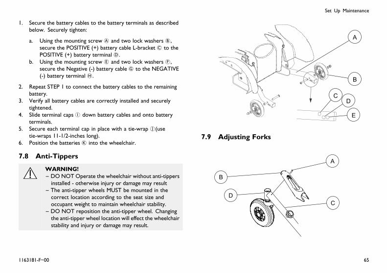
Set Up Maintenance
1. Secure the battery cables to the battery terminals as describedbelow. Securely tighten:
a. Using the mounting screw A and two lock washers B,secure the POSITIVE (+) battery cable L-bracket C to thePOSITIVE (+) battery terminal D.
b. Using the mounting screw E and two lock washers F,secure the Negative (-) battery cable G to the NEGATIVE(-) battery terminal H.
2. Repeat STEP 1 to connect the battery cables to the remainingbattery.
3. Verify all battery cables are correctly installed and securelytightened.
4. Slide terminal caps I down battery cables and onto batteryterminals.
5. Secure each terminal cap in place with a tie-wrap J(usetie-wraps 11-1/2-inches long).
6. Position the batteries K into the wheelchair.
7.8 Anti-Tippers
WARNING!– DONOT Operate the wheelchair without anti-tippersinstalled - otherwise injury or damage may result
– The anti-tipper wheels MUST be mounted in thecorrect location according to the seat size andoccupant weight to maintain wheelchair stability.
– DO NOT reposition the anti-tipper wheel. Changingthe anti-tipper wheel location will effect the wheelchairstability and injury or damage may result.
7.9 Adjusting Forks
1163181-F~00 65

Invacare® FDX® Power Wheelchair Base
This procedure must be performed by a qualified technician.
This procedure applies to both Forks.
1. Remove the mounting screw securing the suspension arm shroudto the suspension arm.
2. Remove the suspension arm shroud from the suspension armand caster headtube.
3. To properly tighten caster journal system and guard againstflutter, perform the following check:
a. Tip the wheelchair forward, toward the floor.b. Pivot both forks and casters to top of their arc
simultaneously.c. Let casters drop to bottom of arc (wheels should swing once
to one-side, then immediately rest in a straight downwardposition).
d. Adjust locknuts according to freedom of caster swing.
4. Test wheelchair for maneuverability.5. Readjust locknuts if necessary, and repeat STEPS 1-3 until
correct.6. Reverse STEPS 1 and 2 to reinstall the suspension arm shroud.
7.10 Repositioning Joystick
1. Turn the adjustment lock lever A to release the joystickmounting tube B from the joystick mounting bracket C.
2. Remove the joystick from the wheelchair.3. Remove the three hex screwsD and washersE that secures the
joystick mounting bracket to the threaded mounting bracket F.4. Reposition threaded mounting bracket on the inside of the
opposite arm tube G as shown.5. Using the three hex mounting screws and washers, secure
joystick mounting bracket to the threaded mounting bracket.6. Slide the joystick mounting tube through the joystick mounting
bracket to the desired position.7. Turn the adjustment lock lever to secure the joystick mounting
tube into the mounting bracket.
66 1163181-F~00

Set Up Maintenance
7.11 Disconnecting/Connecting the SPJ+Joysticks
The joystick connector is located at the rear of the seatframe.
7.11.1 Disconnecting the SPJ+ Joysticks
1. Hold the light grey collar portion A of the joystick connector Bwith one hand and the controller connectorC on the wheelchairin the other and disconnect them by pulling them apart.
7.11.2 Connecting the SPJ+ Joysticks
WARNING!– The joystick connector and controller connectorfit together in one way only. DO NOT force themtogether.
1. Hold the light grey collar portion A of the joystick connector Bwith one hand and the controller connectorC on the wheelchairin the other and align them.
2. Lightly push to engage the joystick connector and the controllerconnector.
7.12 Disconnecting/Connecting the CMPJ+Joysticks
The joystick connector is located at the rear of the seatframe.
7.12.1 Connecting the CMPJ+ JoysticksEnsure the gaskets B are installed in the top connector capand between network connectors C.
1. Ensure the latch is pulled away from the network connector.2. Connect the network connector to the other connectors.3. Top D and Bottom E Connectors - Install connector caps onto
the network connector.4. Push the latch in to secure the network connectors and caps.5. If necessary secure excess cable using tie-wraps.
1163181-F~00 67

Invacare® FDX® Power Wheelchair Base
7.12.2 Disconnecting the CMPJ+ Joysticks
1. Pull the latch A away from the joystick connector.2. Disconnect the joystick connector from the remaining
connectors.
68 1163181-F~00

Troubleshooting
8 Troubleshooting
8.1 Driving Performance
Solutions
Check forloose stemnuts/bolts,bearings orsigns of wear.
Check foruneven tirewear, bentfork/frameor loosehardware.
If pneumatic,check tiresfor correctand equalpressure.
WheelchairVeers Left orRight
X X X
SluggishTurn orPerformance
X X
CastersFlutter
X X X
Squeaks andRattles
X
Looseness inWheelchair
X X
Wheelchair 3Wheels
X X
8.2 ElectricalFor additional troubleshooting information and explanationof error codes, refer to the individual Electronics Manualsupplied with each wheelchair.
8.2.1 SPJ+, SPJ+ w/PSS or SPJ+ w/ACC JoysticksThe joystick information gauge and the service indicator giveindications of the type of fault or error detected by the controlmodule. When a fault is detected, the wheelchair may stop and notdrive. The LEDs on the information gauge may flash in a particularpattern or the service indicator light will flash. The number or typeof flashes indicates the nature of the error. If multiple errors arefound, only the first error encountered by the control module willbe displayed.
Information Gauge Display AAA Diagnostics
Display Description Definition Comments
All LEDs areoff.
Power is off.
1163181-F~00 69

Invacare® FDX® Power Wheelchair Base
All LEDs areon.
Power is on. Fewer than threeLEDs on impliesreduced batterycharge.
Left RedLED isflashing.
Batterycharge islow.
The batteriesshould be chargedas soon aspossible.
Left to Right“chase”alternatingwith steadydisplay.
Joystick isin program-ming, in-hibit and/orchargingmode.
The steady LEDsindicate thecurrent state ofthe battery charge.
All LEDsare flashingslowly.
Joystick hasdetectedOut-of-Neutral-at-Power-Upmode.
Release thejoystick back toNeutral.
Service Indicator Light AAA Diagnostics
NUMBER OFFLASHES
ERRORCODE DE-SCRIPTION
POSSIBLE SOLUTION
1 User Fault Release joystick to neutraland try again.
2 Battery Fault Charge the batteries.
Check that battery cablesare connected properly. Ifnecessary, replace batteries.
3 Left MotorFault
Contact Invacare/Dealer forservice.
4 Right MotorFault
Contact Invacare/Dealer forservice.
70 1163181-F~00

Troubleshooting
5 Left Park BrakeFault
Ensure brake lever is in thedrive position before turningon the wheelchair. Ensuremotor cable is plugged intothe controller.
Contact Invacare/Dealer forservice.
6 Right ParkBrake Fault
Ensure brake lever is in thedrive position before turningon the wheelchair. Ensuremotor cable is plugged intothe controller.
Contact Invacare/Dealer forservice.
7 Remote Fault Check to make sure joystickis connected properly. TurnJoystick off then on.
Contact Invacare/Dealer forservice.
8 ControllerFault
Contact Invacare/Dealer forservice.
9 Communica-tions Fault
Check joystick cableconnections. Check joystickcable and connectors fordamage.
Contact Invacare/Dealer forservice.
10 General Fault Contact Invacare/Dealer forservice.
11 Incompatibleor incorrectRemote
Wrong type of remoteconnected. ContactInvacare/Dealer for service.
8.2.2 CMPJ+, PSR+, PSF+ Joysticks or DisplaysError codes are displayed in the Fault Log on the hand helpprogrammer.
SYMPTOM PROBABLECAUSE SOLUTIONS
LEFT BRAKEFAULT or RIGHTBRAKE FAULTdisplays andwheelchair doesnot drive.
Motor lock leversdisengaged (Errorcode E9 or E10).
Engage motor locklevers. Refer to Dis-engaging/EngagingMotor Lock Levers.
CHARGERPLUGGED INdisplays.
Battery chargerconnected (Errorcode E28).
Unplug batterycharger from thewheelchair. Refer toCharging Batteries.
1163181-F~00 71

Invacare® FDX® Power Wheelchair Base
SYMPTOM PROBABLECAUSE SOLUTIONS
BATTERY FAULTdisplays and thewheelchair does notdrive.
Batteries need to becharged (Error codeE14).
Charge batteries.Refer to ChargingBatteries.
If batteries fail tocharge properly,check batterycharger or replacebatteries. Refer toReplacing Batteriesand/or BatteryCables.
JOYSTICKTIMEOUT displaysand the wheelchairdoes not drive.
Joystick orinput device isdisconnected (Errorcode 32).
Turn off power,reconnect thejoystick of inputdevice and turnpower on.
JOYSTICK FAULTdisplays and thewheelchair does notdrive.
The joystick or inputdevice is sending avalue outside of thereverse, forward,left or right limits(Error codes E01,E02, E03 or E04).
Replace joystick orinput device.
NEUTRALTESTING displays.
The joystick neutraltest has failed (Errorcode E18).
Release the joystickand try to get thejoystick back intothe center-mostposition.
SYMPTOM PROBABLECAUSE SOLUTIONS
BAD JOYSTICKCAL VALUESdisplays and thewheelchair does notdrive.
The joystickcalibration valuesare outside of theexpected range(Error code E19).
Recalibrate thejoystick (joystickthrow procedure).
CTRL NOTCONNECTED
The CMPJ orDisplay module isnot communicatingwith the controlmodule (Error codeE200).
Check theconnectionsbetween the joystickor display and thecontroller. Turn thepower off and thenback on. Replacethe controller ifnecessary.
CTRL COM FAULTdisplays and thewheelchair drivesslowly.
The controller hasdetermined a faultduring a previousturn-off process(Error code E41).
Turn the wheelchairoff and back on.
MISSINGCONFIGURATIONdisplays at powerup.
One or moredevices havebeen removed ordisconnected fromthe wheelchair.
Reconnect thedevice.
72 1163181-F~00

Troubleshooting
SYMPTOM PROBABLECAUSE SOLUTIONS
ATTENDANTACTIVE anddisplays.
The Proportionalor Digital Attendantcontrol is active andcan be used to drivethe chair.
This is normalbehavior.
Batteries drawexcessive currentwhen charging.
Battery failure.
Electricalmalfunction.
Have batterieschecked for shortedcell. Replace ifnecessary.
ContactDealer/Invacarefor service.
Battery indicatorflashes the chargelevel is low -immediately afterrecharge.
Battery failure.
Malfunctioningbattery charger.
Electricalmalfunction.
Check batteriesfor shorted cell.Replace if necessary.
ContactDealer/Invacarefor Service.
ContactDealer/Invacarefor Service.
SYMPTOM PROBABLECAUSE SOLUTIONS
Battery indicatorflashes the chargelevel is low - toosoon after beingrecharged.
Batteries notcharged.
Weak batteries.
Have chargerchecked.
Replace batteries ifnecessary. Refer toReplacing Batteriesand/or BatteryCables.
Motor “chatters” orruns irregular.
Motor/gearboxmalfunction.
Stop use ofWheelchair.ContactDealer/Invacarefor Service.
Joystick erratic ordoes not respond asdesired.
Damaged motorcoupling.
Electricalmalfunction.
Controllerprogrammedimproperly.
ContactDealer/Invacarefor Service.
ContactDealer/Invacarefor Service.
ContactDealer/Invacareto have controllerreprogrammed.
1163181-F~00 73

Invacare® FDX® Power Wheelchair Base
SYMPTOM PROBABLECAUSE SOLUTIONS
Wheelchair doesnot respond tocommands.
Electricalmalfunction.
ContactDealer/Invacarefor Service.
Power indicatoroff - even afterrecharging.
Poor batteryterminal connection.
Have terminalscleaned.
8.3 Checking Battery Charge LevelThe following “Do’s” and “Don’ts” are provided for your convenienceand safety.
DON’T DO
Don’t perform any installationor maintenance without firstreading this manual.
Read and understand thismanual and any serviceinformation that accompaniesa battery and charger beforeoperating the wheelchair.
Don’t perform installation ormaintenance of batteries in anarea that could be damaged bybattery spills.
Move the wheelchair to a workarea before cleaning terminals,or opening battery box.
Don’t make it a habit todischarge batteries to thelowest level.
Recharge as frequently aspossible to maintain a highcharge level and extend batterylife.
Don’t use randomly chosenbatteries or chargers.
Follow recommendations in thismanual when selecting a batteryor charger.
DON’T DO
Don’t put new batteries intoservice before charging.
Fully charge a new batterybefore using.
Don’t tip or tilt batteries. Use a carrying strap to remove,move or install a battery.
Don’t tap on clamps andterminals with tools.
Push battery clamps on theterminals. Spread clamps widerif necessary.
Don’t mismatch your batteryand chargers.
Use only a gel charger for a gelbattery.
74 1163181-F~00

Notes

USA One Invacare Way, Elyria, Ohio USA, 44036–2125, 800–333–6900
Canada 570 Matheson Blvd E Unit 8, Mississauga Ontario, L4Z 4G4 Canada, 800–668–5324
www.invacare.com
1163181-F~00 2015-11-5
*1163181F~00*Making Life’s Experiences Possible™