Embed Size (px)
Citation preview
Introduction 1-1
Networking Overview
Introduction 1-2
Introduction
Introduction 1-3
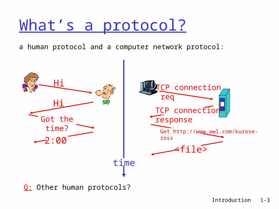
What’s a protocol?a human protocol and a computer network protocol:
Q: Other human protocols?
Hi
Hi
Got thetime?
2:00
TCP connection req
TCP connectionresponse
Get http://www.awl.com/kurose-ross
<file>
time
Introduction 1-4
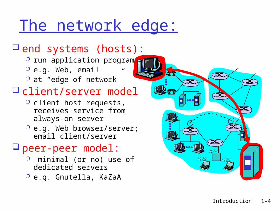
The network edge: end systems (hosts):
run application programs e.g. Web, email at “edge of network”
client/server model client host requests, receives
service from always-on server e.g. Web browser/server; email
client/server
peer-peer model: minimal (or no) use of
dedicated servers e.g. Gnutella, KaZaA
Introduction 1-5
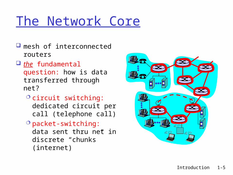
The Network Core
mesh of interconnected routers
the fundamental question: how is data transferred through net? circuit switching:
dedicated circuit per call (telephone call)
packet-switching: data sent thru net in discrete “chunks” (internet)
Introduction 1-6
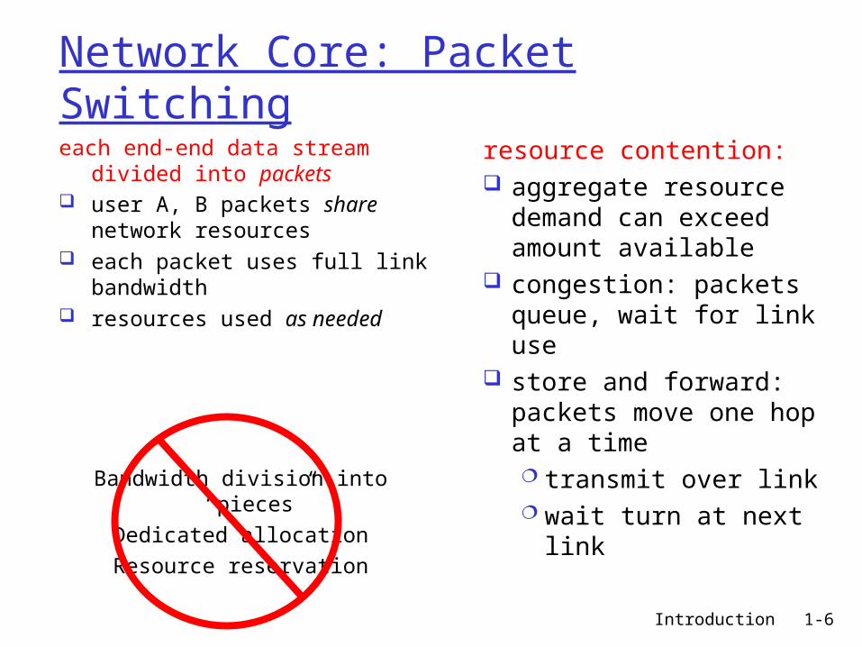
Network Core: Packet Switching
each end-end data stream divided into packets
user A, B packets share network resources
each packet uses full link bandwidth resources used as needed
resource contention: aggregate resource
demand can exceed amount available
congestion: packets queue, wait for link use
store and forward: packets move one hop at a time transmit over link wait turn at next link
Bandwidth division into “pieces”
Dedicated allocation
Resource reservation
Introduction 1-7
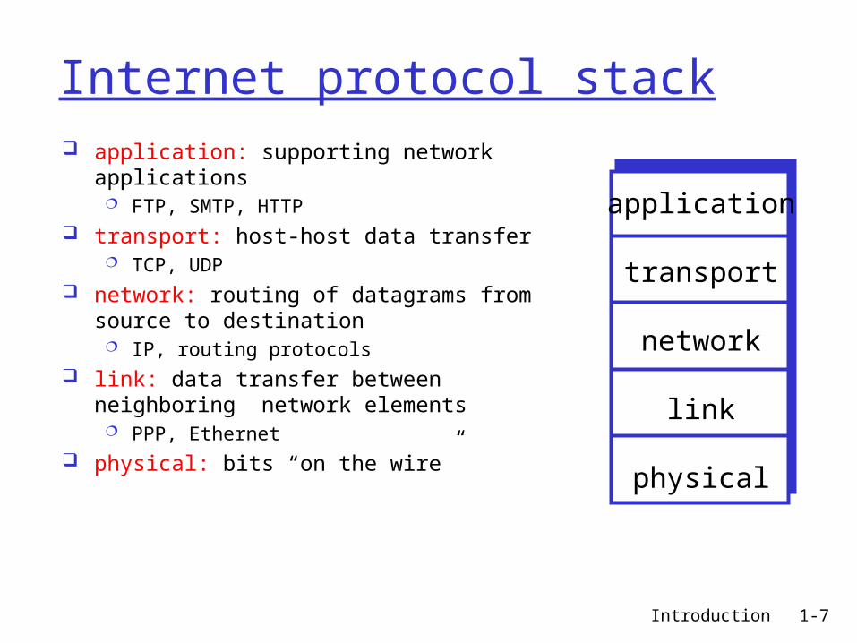
Internet protocol stack application: supporting network applications
FTP, SMTP, HTTP transport: host-host data transfer
TCP, UDP network: routing of datagrams from source to
destination IP, routing protocols
link: data transfer between neighboring network elements
PPP, Ethernet physical: bits “on the wire”
application
transport
network
link
physical
Introduction 1-8
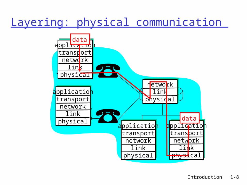
Layering: physical communication
applicationtransportnetwork
linkphysical
applicationtransportnetwork
linkphysical
applicationtransportnetwork
linkphysical
applicationtransportnetwork
linkphysical
networklink
physical
data
data
Introduction 1-9
Application Layer
Introduction 1-10
Network applications: some jargon
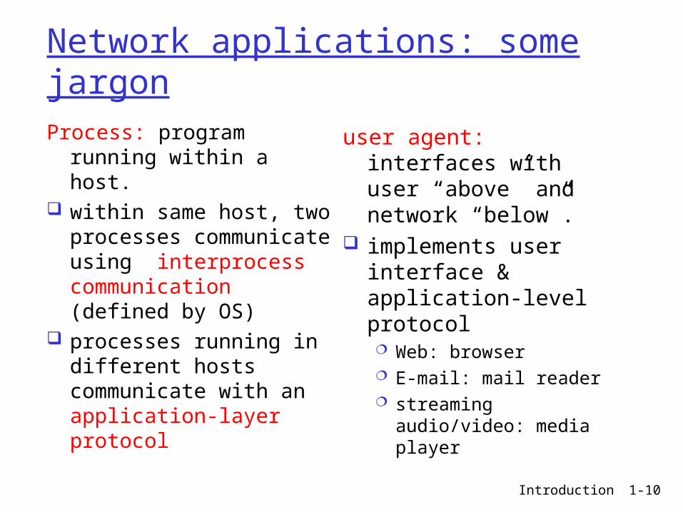
Process: program running within a host.
within same host, two processes communicate using interprocess communication (defined by OS)
processes running in different hosts communicate with an application-layer protocol
user agent: interfaces with user “above” and network “below”.
implements user interface & application-level protocol Web: browser E-mail: mail reader streaming audio/video:
media player
Introduction 1-11
Applications and application-layer protocols
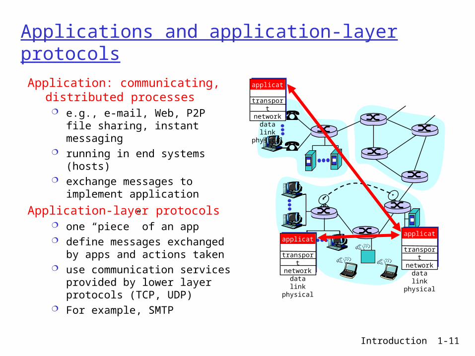
Application: communicating, distributed processes
e.g., e-mail, Web, P2P file sharing, instant messaging
running in end systems (hosts) exchange messages to implement
application
Application-layer protocols one “piece” of an app define messages exchanged by
apps and actions taken use communication services
provided by lower layer protocols (TCP, UDP)
For example, SMTP
applicationtransportnetworkdata linkphysical
applicationtransportnetworkdata linkphysical
applicationtransportnetworkdata linkphysical
Introduction 1-12
Client-server paradigm (“usual” approach)
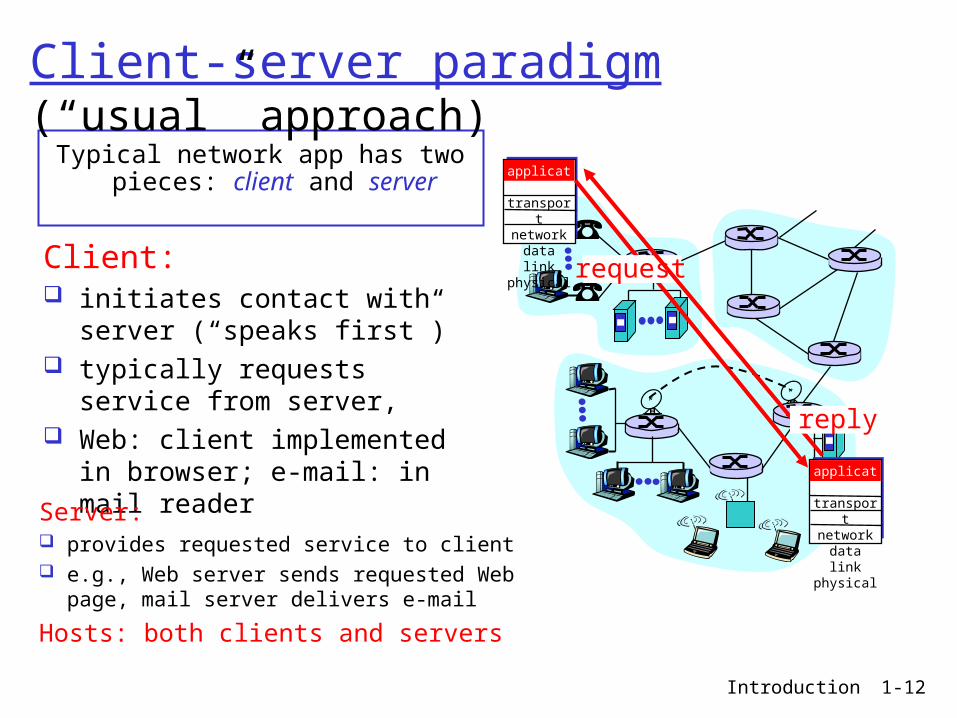
Typical network app has two pieces: client and server
applicationtransportnetworkdata linkphysical
applicationtransportnetworkdata linkphysical
Client: initiates contact with server
(“speaks first”) typically requests service from
server, Web: client implemented in
browser; e-mail: in mail reader
request
reply
Server: provides requested service to client e.g., Web server sends requested Web page, mail
server delivers e-mail
Hosts: both clients and servers
Introduction 1-13
Addressing processes: For a process to receive
messages, it must have an identifier
Every host has a unique 32-bit IP address
Q: does the IP address of the host on which the process runs suffice for identifying the process?
A: No, many processes can be running on same host
Identifier includes both the IP address and port numbers associated with the process on the host.
“Well-known” port number examples: HTTP server: 80 Mail server: 25
Introduction 1-14
Internet transport protocols services
TCP service: connection-oriented: setup
required between client and server processes
reliable transport between sending and receiving process
flow control: sender won’t overwhelm receiver
congestion control: throttle sender when network overloaded
full duplex: simultaneous 2-way communication
does not provide: timing, minimum bandwidth guarantees
UDP service: unreliable data transfer
between sending and receiving process
does not provide: connection setup, reliability, flow control, congestion control, timing, or bandwidth guarantee
Q: Why is there a UDP?
Introduction 1-15
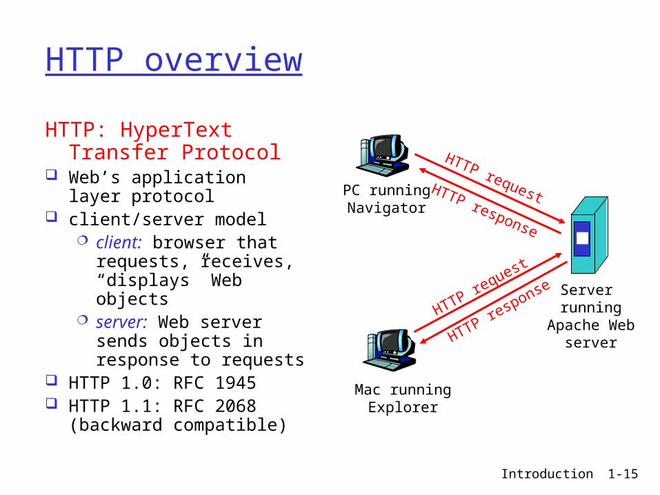
HTTP overview
HTTP: HyperText Transfer Protocol
Web’s application layer protocol
client/server model client: browser that
requests, receives, “displays” Web objects
server: Web server sends objects in response to requests
HTTP 1.0: RFC 1945 HTTP 1.1: RFC 2068
(backward compatible)
PC runningNavigator
Server running
Apache Webserver
Mac runningExplorer
HTTP request
HTTP request
HTTP response
HTTP response
Introduction 1-16
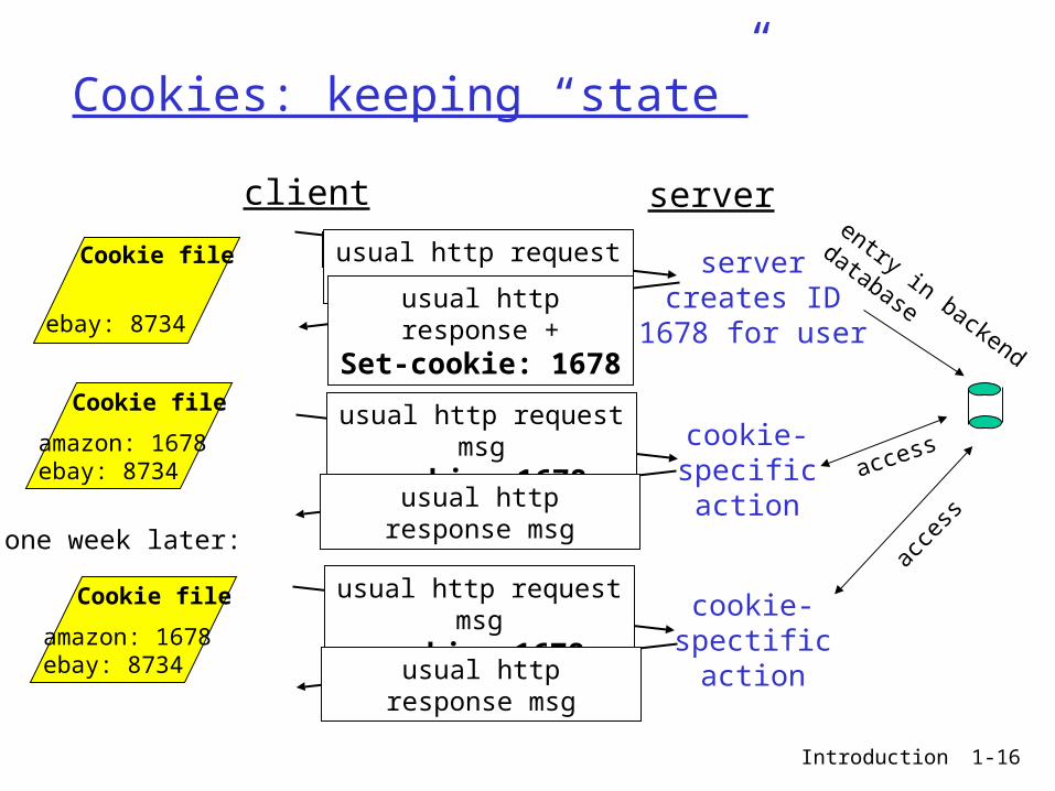
Cookies: keeping “state”
client server
usual http request msg
usual http response +Set-cookie: 1678
usual http request msgcookie: 1678
usual http response msg
usual http request msgcookie: 1678
usual http response msg
cookie-specificaction
cookie-spectificaction
servercreates ID
1678 for user
entry in backend
database
access
acce
ss
Cookie file
amazon: 1678ebay: 8734
Cookie file
ebay: 8734
Cookie file
amazon: 1678ebay: 8734
one week later:
Introduction 1-17
Cookies (continued)
What cookies can bring: authorization shopping carts recommendations user session state (Web
e-mail)
Cookies and privacy: cookies permit sites to
learn a lot about you you may supply name
and e-mail to sites search engines use
redirection & cookies to learn yet more
advertising companies obtain info across sites
aside
Introduction 1-18
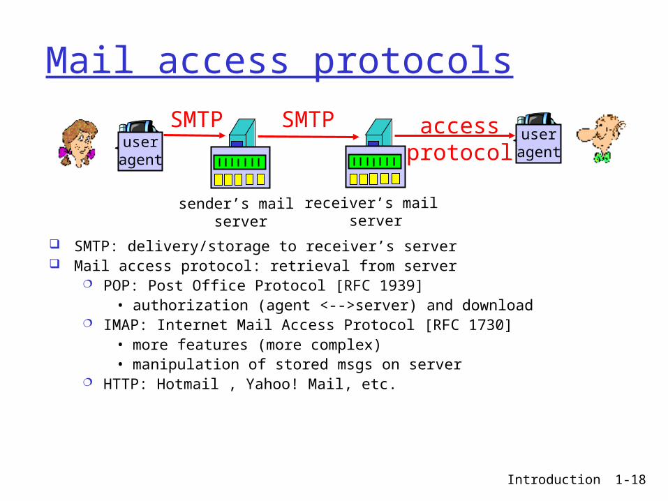
Mail access protocols
SMTP: delivery/storage to receiver’s server Mail access protocol: retrieval from server
POP: Post Office Protocol [RFC 1939]• authorization (agent <-->server) and download
IMAP: Internet Mail Access Protocol [RFC 1730]• more features (more complex)• manipulation of stored msgs on server
HTTP: Hotmail , Yahoo! Mail, etc.
useragent
sender’s mail server
useragent
SMTP SMTP accessprotocol
receiver’s mail server
Introduction 1-19
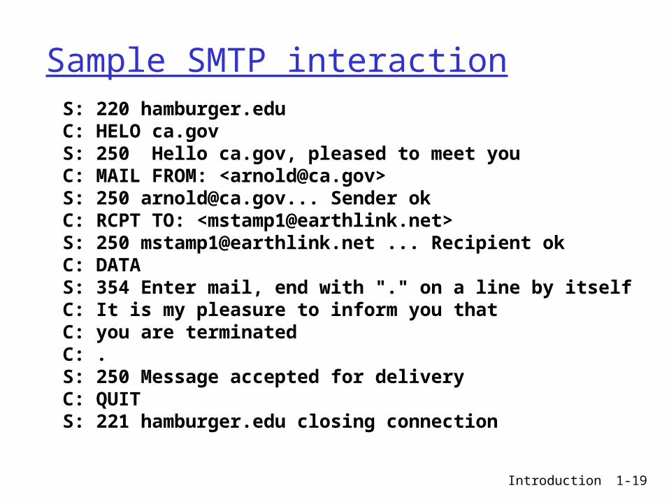
Sample SMTP interaction S: 220 hamburger.edu C: HELO ca.gov S: 250 Hello ca.gov, pleased to meet you C: MAIL FROM: <[email protected]> S: 250 [email protected]... Sender ok C: RCPT TO: <[email protected]> S: 250 [email protected] ... Recipient ok C: DATA S: 354 Enter mail, end with "." on a line by itself C: It is my pleasure to inform you that C: you are terminated C: . S: 250 Message accepted for delivery C: QUIT S: 221 hamburger.edu closing connection
Introduction 1-20
DNS: Domain Name System
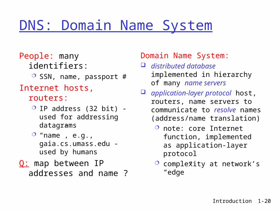
People: many identifiers: SSN, name, passport #
Internet hosts, routers: IP address (32 bit) - used
for addressing datagrams
“name”, e.g., gaia.cs.umass.edu - used by humans
Q: map between IP addresses and name ?
Domain Name System: distributed database implemented
in hierarchy of many name servers application-layer protocol host,
routers, name servers to communicate to resolve names (address/name translation) note: core Internet function,
implemented as application-layer protocol
complexity at network’s “edge”
Introduction 1-21
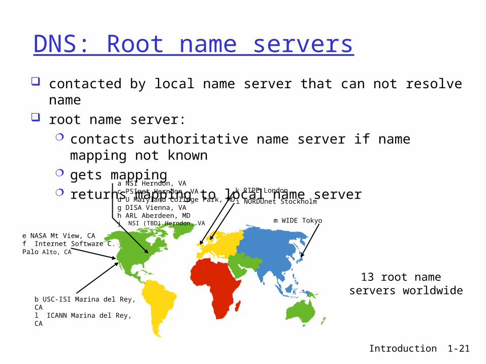
DNS: Root name servers contacted by local name server that can not resolve name root name server:
contacts authoritative name server if name mapping not known gets mapping returns mapping to local name server
b USC-ISI Marina del Rey, CAl ICANN Marina del Rey, CA
e NASA Mt View, CAf Internet Software C. Palo Alto, CA
i NORDUnet Stockholm
k RIPE London
m WIDE Tokyo
a NSI Herndon, VAc PSInet Herndon, VAd U Maryland College Park, MDg DISA Vienna, VAh ARL Aberdeen, MDj NSI (TBD) Herndon, VA
13 root name servers worldwide
Introduction 1-22
P2P file sharing
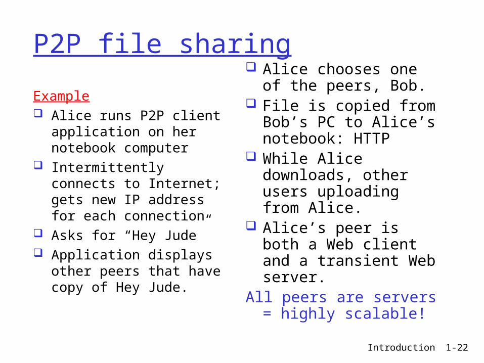
Example Alice runs P2P client
application on her notebook computer
Intermittently connects to Internet; gets new IP address for each connection
Asks for “Hey Jude” Application displays other
peers that have copy of Hey Jude.
Alice chooses one of the peers, Bob.
File is copied from Bob’s PC to Alice’s notebook: HTTP
While Alice downloads, other users uploading from Alice.
Alice’s peer is both a Web client and a transient Web server.
All peers are servers = highly scalable!
Introduction 1-23
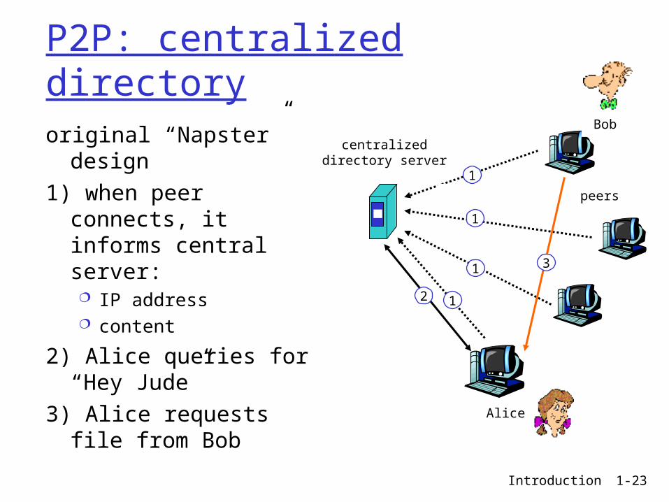
P2P: centralized directory
original “Napster” design
1) when peer connects, it informs central server: IP address content
2) Alice queries for “Hey Jude”
3) Alice requests file from Bob
centralizeddirectory server
peers
Alice
Bob
1
1
1
12
3
Introduction 1-24
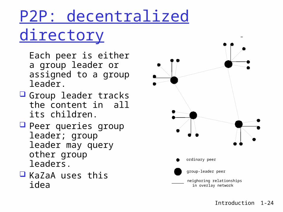
P2P: decentralized directory
Each peer is either a group leader or assigned to a group leader.
Group leader tracks the content in all its children.
Peer queries group leader; group leader may query other group leaders.
KaZaA uses this idea
ordinary peer
group-leader peer
neighoring relationshipsin overlay network
Introduction 1-25
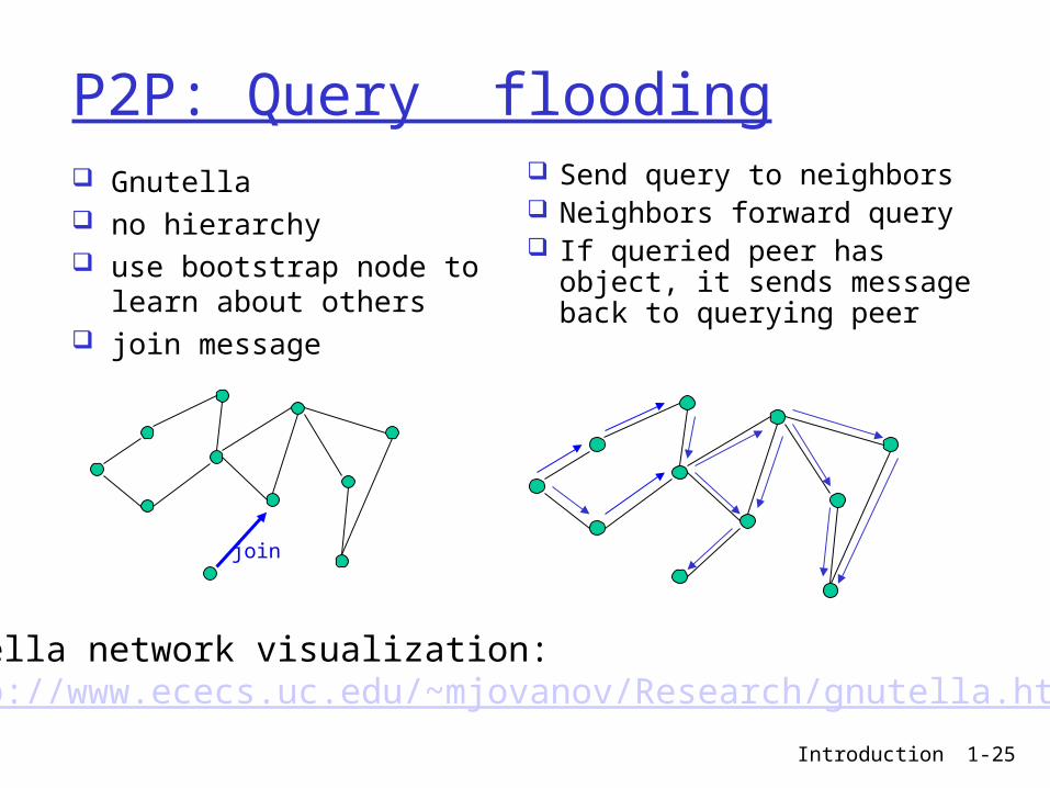
P2P: Query flooding Gnutella no hierarchy use bootstrap node to learn
about others join message
Send query to neighbors Neighbors forward query If queried peer has object,
it sends message back to querying peer
join
Gnutella network visualization: http://www.ececs.uc.edu/~mjovanov/Research/gnutella.html
Introduction 1-26
Transport Layer
Introduction 1-27
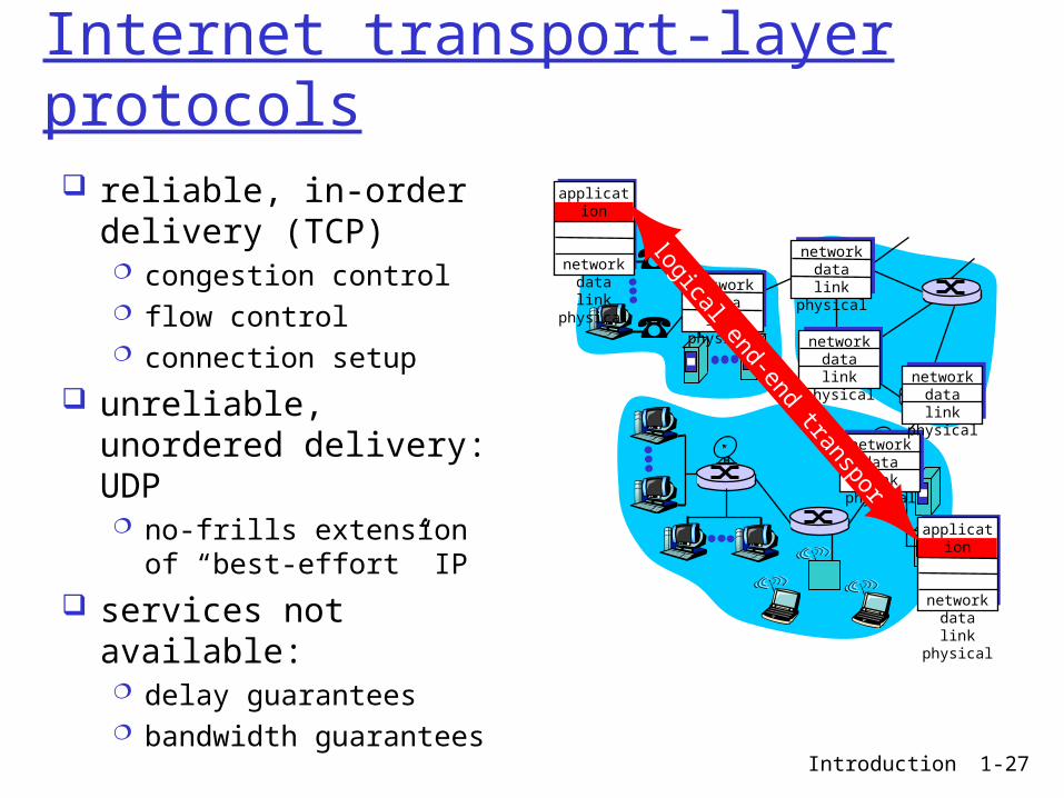
Internet transport-layer protocols
reliable, in-order delivery (TCP) congestion control flow control connection setup
unreliable, unordered delivery: UDP no-frills extension of “best-
effort” IP
services not available: delay guarantees bandwidth guarantees
applicationtransportnetworkdata linkphysical
applicationtransportnetworkdata linkphysical
networkdata linkphysical
networkdata linkphysical
networkdata linkphysical
networkdata linkphysicalnetwork
data linkphysical
logical end-end transport
Introduction 1-28
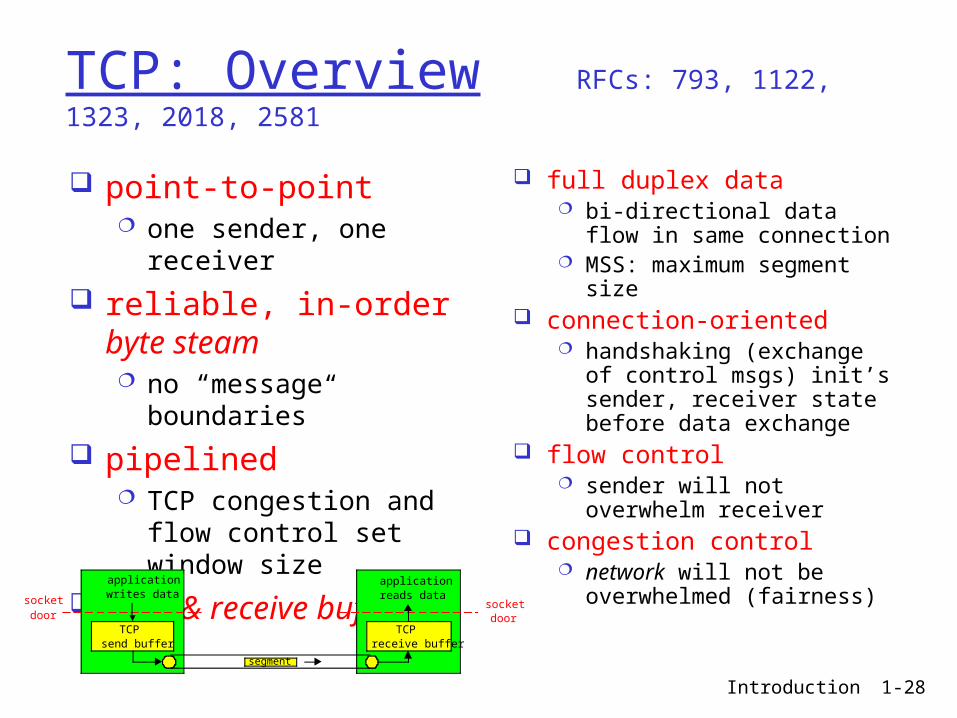
TCP: Overview RFCs: 793, 1122, 1323, 2018, 2581
full duplex data bi-directional data flow in
same connection MSS: maximum segment
size connection-oriented
handshaking (exchange of control msgs) init’s sender, receiver state before data exchange
flow control sender will not overwhelm
receiver congestion control
network will not be overwhelmed (fairness)
point-to-point one sender, one receiver
reliable, in-order byte steam no “message boundaries”
pipelined TCP congestion and flow
control set window size
send & receive buffers
socketdoor
TCPsend buffer
TCPreceive buffer
socketdoor
segment
applicationwrites data
applicationreads data
Introduction 1-29
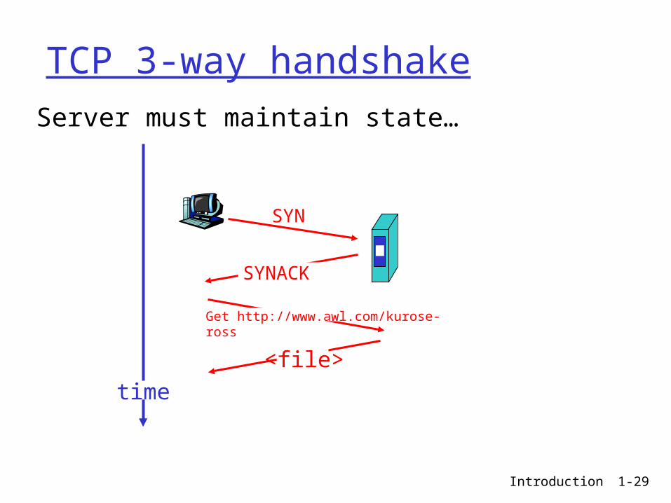
TCP 3-way handshake
Server must maintain state…
SYN
SYNACK
Get http://www.awl.com/kurose-ross
<file>
time
Introduction 1-30
Network Layer
Introduction 1-31
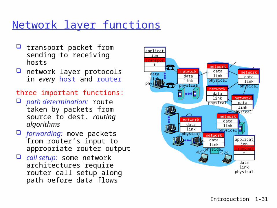
Network layer functions
transport packet from sending to receiving hosts
network layer protocols in every host and router
three important functions: path determination: route taken by
packets from source to dest. routing algorithms
forwarding: move packets from router’s input to appropriate router output
call setup: some network architectures require router call setup along path before data flows
networkdata linkphysical
networkdata linkphysical
networkdata linkphysical
networkdata linkphysical
networkdata linkphysical
networkdata linkphysical
networkdata linkphysical
networkdata linkphysical
applicationtransportnetworkdata linkphysical
applicationtransportnetworkdata linkphysical
Introduction 1-32
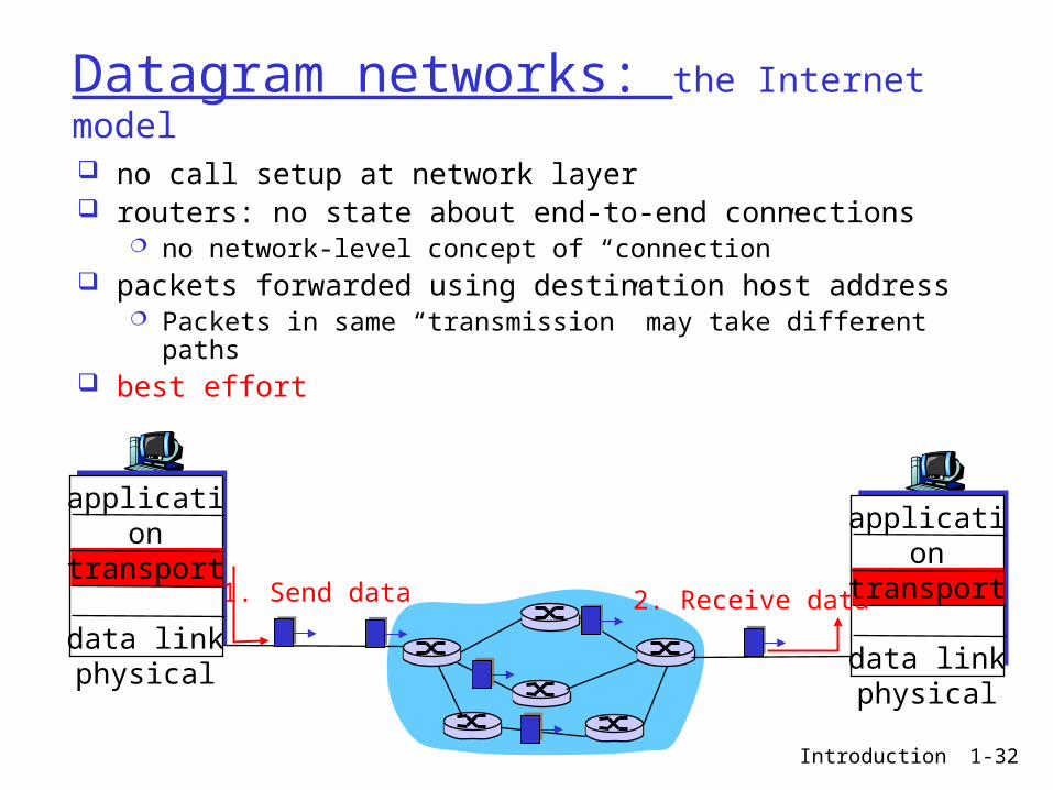
Datagram networks: the Internet model
no call setup at network layer routers: no state about end-to-end connections
no network-level concept of “connection” packets forwarded using destination host address
Packets in same “transmission” may take different paths best effort
applicationtransportnetworkdata linkphysical
applicationtransportnetworkdata linkphysical
1. Send data 2. Receive data
Introduction 1-33
Hierarchical Routing
aggregate routers into regions, “autonomous systems” (AS)
routers in same AS run same routing protocol “intra-AS” routing
protocol routers in different AS
can run different intra-AS routing protocol
special routers in AS run intra-AS routing protocol
with all other routers in AS also responsible for routing
to destinations outside AS run inter-AS routing
protocol with other gateway routers
gateway routers
Introduction 1-34
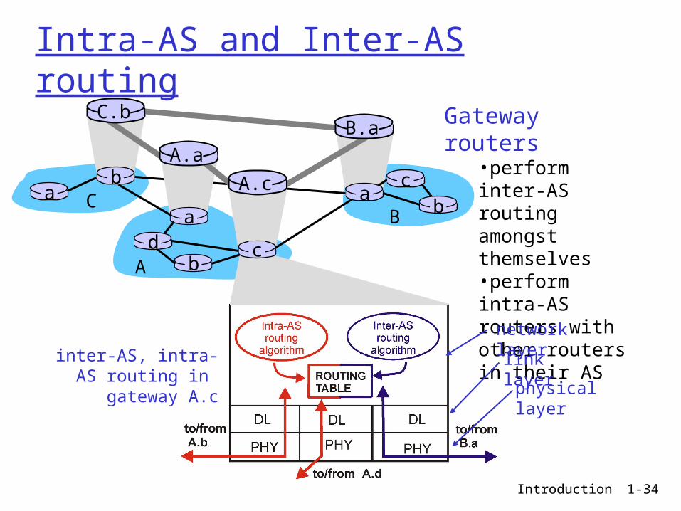
Intra-AS and Inter-AS routing
Gateway routers•perform inter-AS routing amongst themselves•perform intra-AS routers with other routers in their AS
inter-AS, intra-AS routing in
gateway A.c
network layer
link layer
physical layer
a
b
b
aaC
A
Bd
A.a
A.c
C.bB.a
cb
c
Introduction 1-35
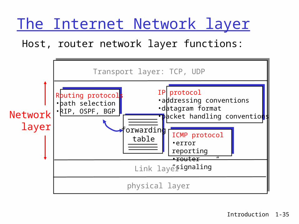
The Internet Network layer
forwardingtable
Host, router network layer functions:
Routing protocols•path selection•RIP, OSPF, BGP
IP protocol•addressing conventions•datagram format•packet handling conventions
ICMP protocol•error reporting•router “signaling”
Transport layer: TCP, UDP
Link layer
physical layer
Networklayer
Introduction 1-36
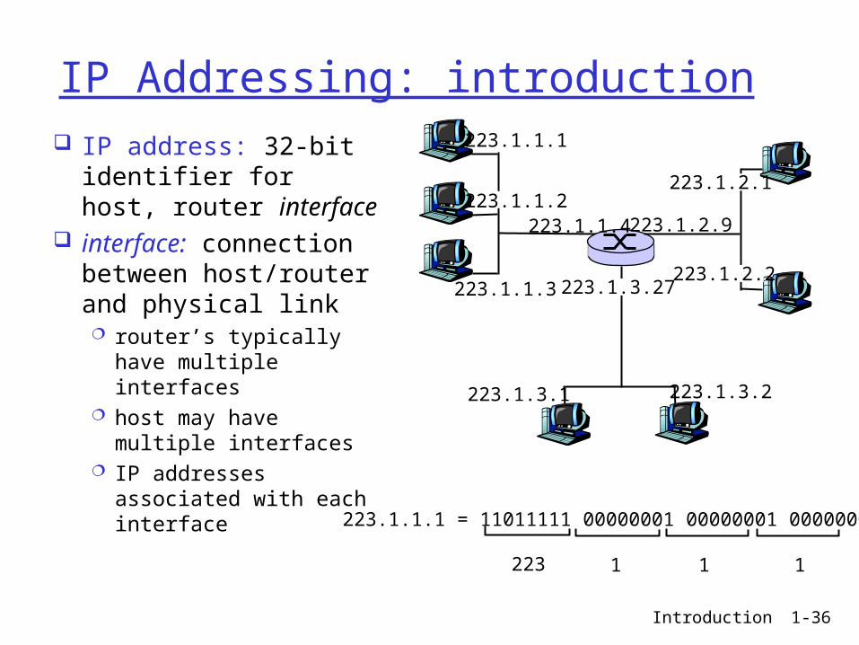
IP Addressing: introduction
IP address: 32-bit identifier for host, router interface
interface: connection between host/router and physical link router’s typically have
multiple interfaces host may have multiple
interfaces IP addresses
associated with each interface
223.1.1.1
223.1.1.2
223.1.1.3
223.1.1.4 223.1.2.9
223.1.2.2
223.1.2.1
223.1.3.2223.1.3.1
223.1.3.27
223.1.1.1 = 11011111 00000001 00000001 00000001
223 1 11
Introduction 1-37
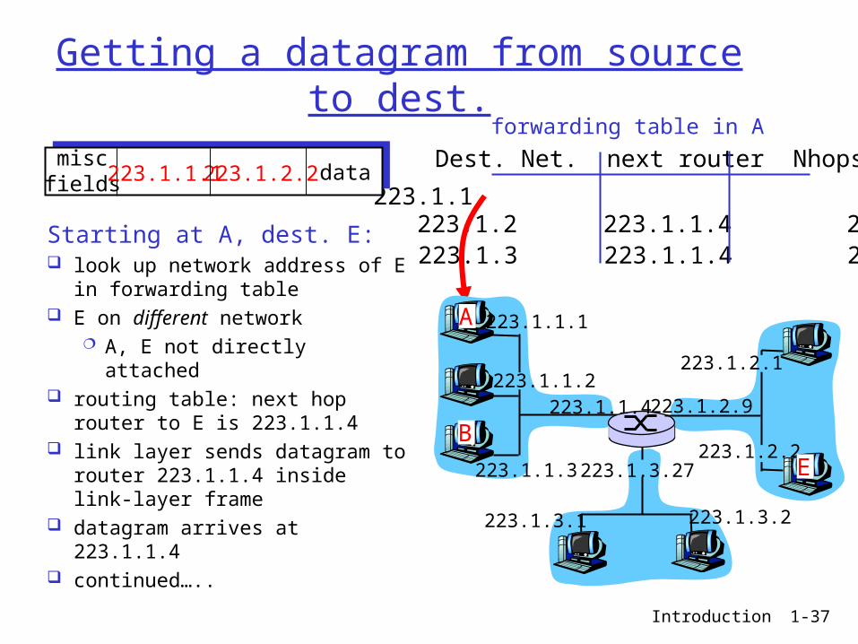
Getting a datagram from source to dest.
Dest. Net. next router Nhops
223.1.1 1223.1.2 223.1.1.4 2223.1.3 223.1.1.4 2
Starting at A, dest. E: look up network address of E in
forwarding table E on different network
A, E not directly attached routing table: next hop router to
E is 223.1.1.4 link layer sends datagram to
router 223.1.1.4 inside link-layer frame
datagram arrives at 223.1.1.4 continued…..
miscfields 223.1.1.1 223.1.2.2 data
223.1.1.1
223.1.1.2
223.1.1.3
223.1.1.4 223.1.2.9
223.1.2.2
223.1.2.1
223.1.3.2223.1.3.1
223.1.3.27
A
B
E
forwarding table in A
Introduction 1-38
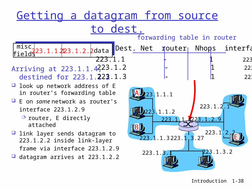
Getting a datagram from source to dest.
Arriving at 223.1.1.4, destined for 223.1.2.2
look up network address of E in router’s forwarding table
E on same network as router’s
interface 223.1.2.9 router, E directly attached
link layer sends datagram to 223.1.2.2 inside link-layer frame
via interface 223.1.2.9 datagram arrives at 223.1.2.2
miscfields 223.1.1.1 223.1.2.2 data Dest. Net router Nhops interface
223.1.1 - 1 223.1.1.4 223.1.2 - 1 223.1.2.9
223.1.3 - 1 223.1.3.27
223.1.1.1
223.1.1.2
223.1.1.3
223.1.1.4 223.1.2.9
223.1.2.2
223.1.2.1
223.1.3.2223.1.3.1
223.1.3.27
A
B
E
forwarding table in router
Introduction 1-39
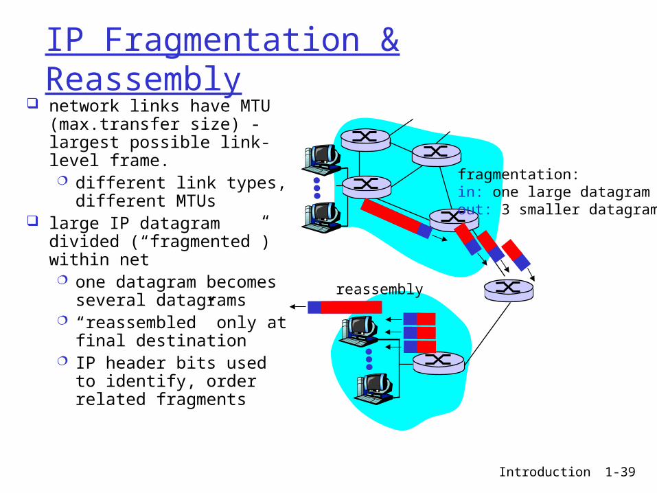
IP Fragmentation & Reassembly network links have MTU
(max.transfer size) - largest possible link-level frame. different link types,
different MTUs large IP datagram divided
(“fragmented”) within net one datagram becomes
several datagrams “reassembled” only at
final destination IP header bits used to
identify, order related fragments
fragmentation: in: one large datagramout: 3 smaller datagrams
reassembly
Introduction 1-40
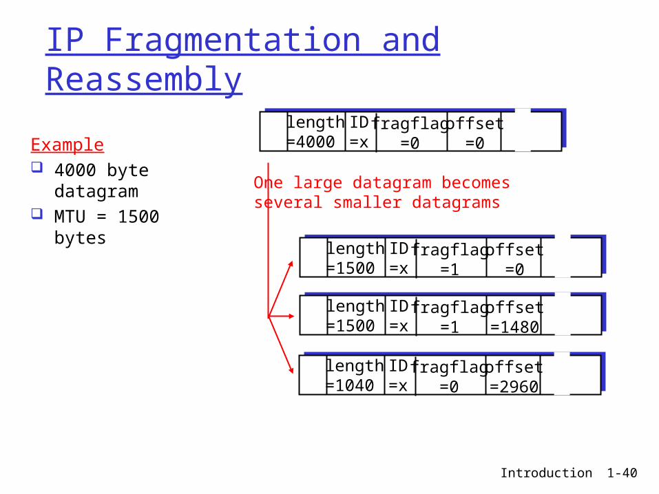
IP Fragmentation and Reassembly
ID=x
offset=0
fragflag=0
length=4000
ID=x
offset=0
fragflag=1
length=1500
ID=x
offset=1480
fragflag=1
length=1500
ID=x
offset=2960
fragflag=0
length=1040
One large datagram becomesseveral smaller datagrams
Example 4000 byte datagram MTU = 1500 bytes
Introduction 1-41
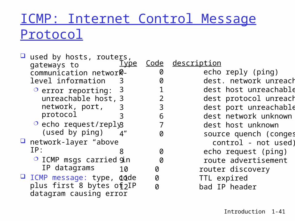
ICMP: Internet Control Message Protocol
used by hosts, routers, gateways to communication network-level information error reporting:
unreachable host, network, port, protocol
echo request/reply (used by ping)
network-layer “above” IP: ICMP msgs carried in IP
datagrams ICMP message: type, code
plus first 8 bytes of IP datagram causing error
Type Code description0 0 echo reply (ping)3 0 dest. network unreachable3 1 dest host unreachable3 2 dest protocol unreachable3 3 dest port unreachable3 6 dest network unknown3 7 dest host unknown4 0 source quench (congestion control - not used)8 0 echo request (ping)9 0 route advertisement10 0 router discovery11 0 TTL expired12 0 bad IP header
Introduction 1-42
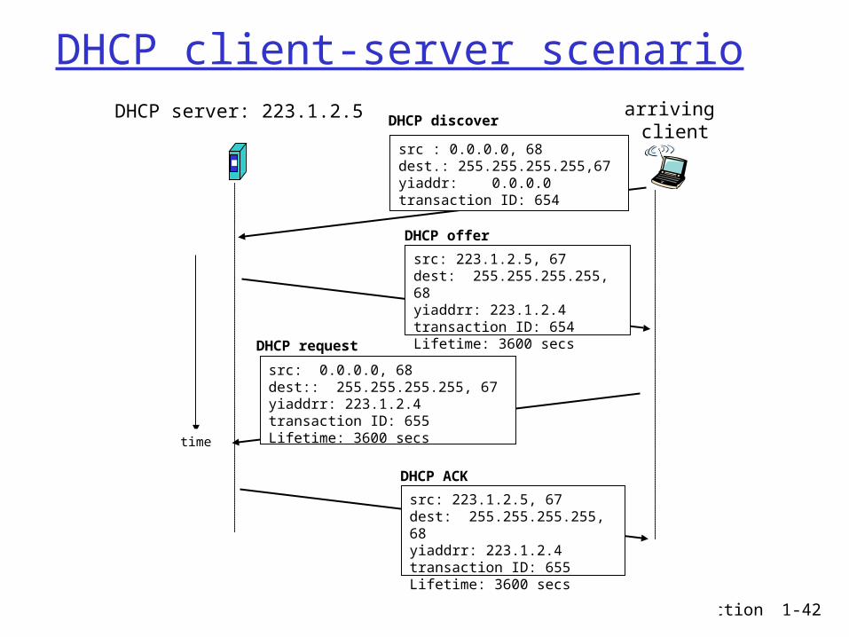
DHCP client-server scenarioDHCP server: 223.1.2.5 arriving
client
time
DHCP discover
src : 0.0.0.0, 68 dest.: 255.255.255.255,67yiaddr: 0.0.0.0transaction ID: 654
DHCP offer
src: 223.1.2.5, 67 dest: 255.255.255.255, 68yiaddrr: 223.1.2.4transaction ID: 654Lifetime: 3600 secs
DHCP request
src: 0.0.0.0, 68 dest:: 255.255.255.255, 67yiaddrr: 223.1.2.4transaction ID: 655Lifetime: 3600 secs
DHCP ACK
src: 223.1.2.5, 67 dest: 255.255.255.255, 68yiaddrr: 223.1.2.4transaction ID: 655Lifetime: 3600 secs
Introduction 1-43
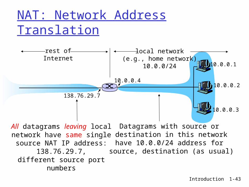
NAT: Network Address Translation
10.0.0.1
10.0.0.2
10.0.0.3
10.0.0.4
138.76.29.7
local network(e.g., home network)
10.0.0/24
rest ofInternet
Datagrams with source or destination in this network
have 10.0.0/24 address for source, destination (as usual)
All datagrams leaving localnetwork have same single source
NAT IP address: 138.76.29.7,different source port numbers
Introduction 1-44
Intra-AS Routing
Also known as Interior Gateway Protocols (IGP) Most common Intra-AS routing protocols:
RIP: Routing Information Protocol
OSPF: Open Shortest Path First
IGRP: Interior Gateway Routing Protocol (Cisco proprietary)
Introduction 1-45
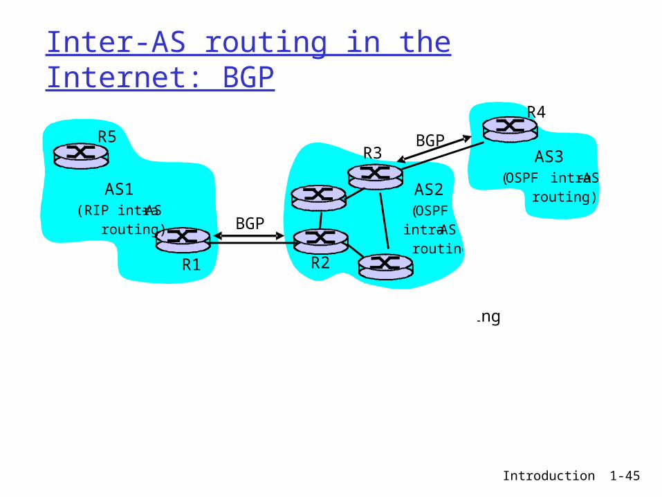
Inter-AS routing in the Internet: BGP
Figure 4.5.2-new2: BGP use for inter-domain routing
AS2 (OSPF
intra-AS routing)
AS1 (RIP intra-AS
routing) BGP
AS3 (OSPF intra-AS
routing)
BGP
R1 R2
R3
R4
R5
Introduction 1-46
Why different Intra- and Inter-AS routing ?
Policy: Inter-AS: admin wants control over how its traffic routed, who routes
through its net. Intra-AS: single admin, so no policy decisions needed
Scale: Hierarchical routing saves table size, reduced update traffic
Performance: Intra-AS: can focus on performance Inter-AS: policy may dominate over performance
Introduction 1-47
Link Layer
Introduction 1-48
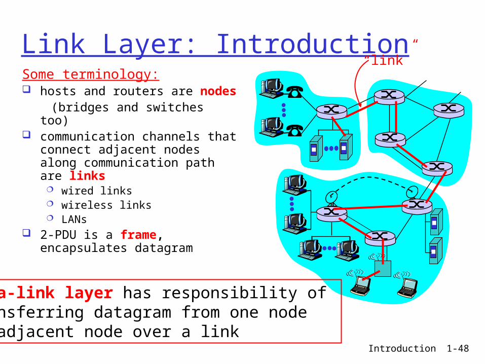
Link Layer: IntroductionSome terminology: hosts and routers are nodes (bridges and switches too) communication channels that
connect adjacent nodes along communication path are links
wired links wireless links LANs
2-PDU is a frame, encapsulates datagram
“link”
data-link layer has responsibility of transferring datagram from one node to adjacent node over a link
Introduction 1-49
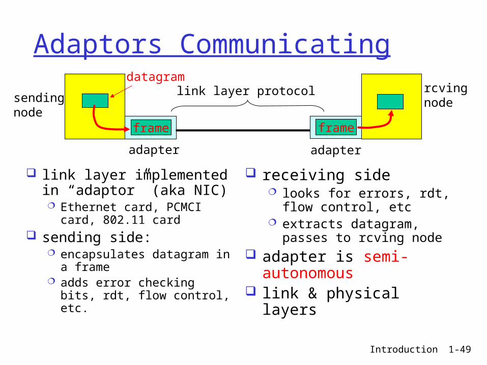
Adaptors Communicating
link layer implemented in “adaptor” (aka NIC) Ethernet card, PCMCI card,
802.11 card sending side:
encapsulates datagram in a frame
adds error checking bits, rdt, flow control, etc.
receiving side looks for errors, rdt, flow
control, etc extracts datagram, passes
to rcving node adapter is semi-
autonomous link & physical layers
sendingnode
frame
rcvingnode
datagram
frame
adapter adapter
link layer protocol
Introduction 1-50
Multiple Access protocols single shared broadcast channel two or more simultaneous transmissions by nodes:
interference only one node can send successfully at a time
multiple access protocol distributed algorithm that determines how nodes share
channel, i.e., determine when node can transmit communication about channel sharing must use channel
itself (in-band signalling)
Introduction 1-51
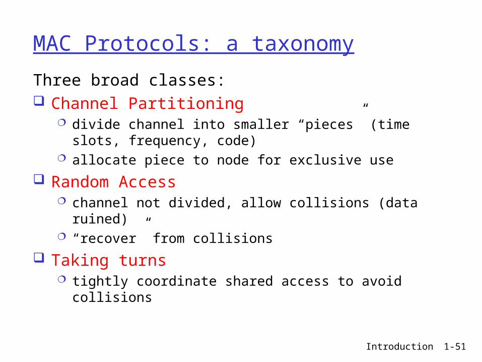
MAC Protocols: a taxonomy
Three broad classes: Channel Partitioning
divide channel into smaller “pieces” (time slots, frequency, code)
allocate piece to node for exclusive use
Random Access channel not divided, allow collisions (data ruined) “recover” from collisions
Taking turns tightly coordinate shared access to avoid collisions
Introduction 1-52
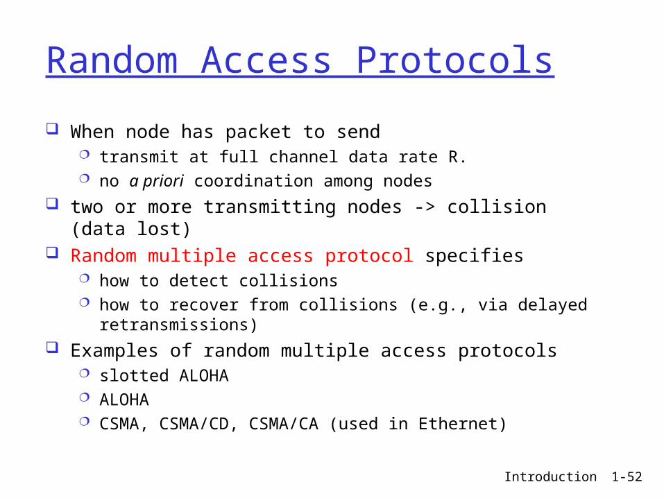
Random Access Protocols
When node has packet to send transmit at full channel data rate R. no a priori coordination among nodes
two or more transmitting nodes -> collision (data lost) Random multiple access protocol specifies
how to detect collisions how to recover from collisions (e.g., via delayed retransmissions)
Examples of random multiple access protocols slotted ALOHA ALOHA CSMA, CSMA/CD, CSMA/CA (used in Ethernet)
Introduction 1-53
CSMA
Carrier Sense Mulitple Access (CSMA): listen before transmitting
If channel is idle, transmit entire frame If channel is busy, wait
Human analogy: don’t interrupt others!
Introduction 1-54
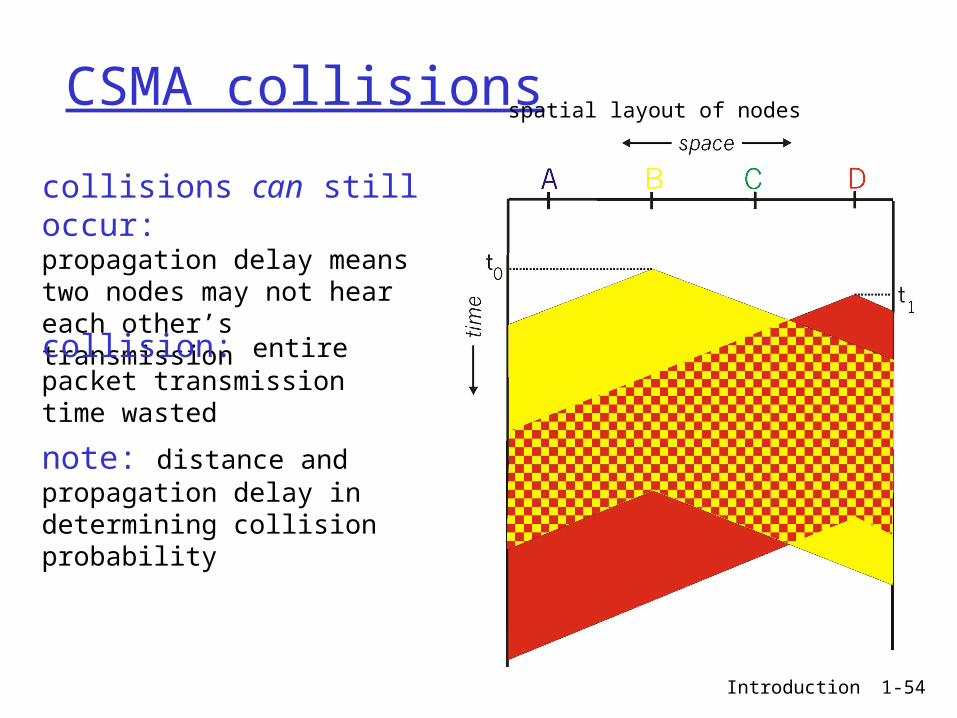
CSMA collisions
collisions can still occur:propagation delay means two nodes may not heareach other’s transmission
collision: entire packet transmission time wasted
spatial layout of nodes
note: distance and propagation delay in determining collision probability
Introduction 1-55
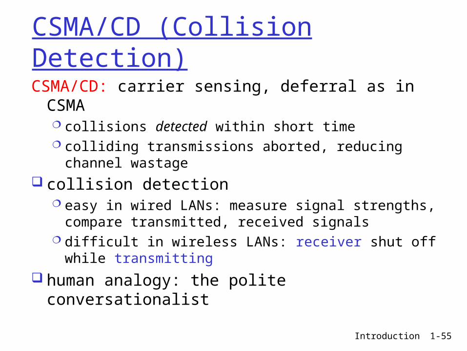
CSMA/CD (Collision Detection)
CSMA/CD: carrier sensing, deferral as in CSMA collisions detected within short time colliding transmissions aborted, reducing channel
wastage collision detection
easy in wired LANs: measure signal strengths, compare transmitted, received signals
difficult in wireless LANs: receiver shut off while transmitting
human analogy: the polite conversationalist
Introduction 1-56
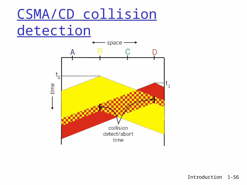
CSMA/CD collision detection
Introduction 1-57
Ethernet uses CSMA/CD
No slots adapter doesn’t transmit if
it senses that some other adapter is transmitting, that is, carrier sense
transmitting adapter aborts when it senses that another adapter is transmitting, that is, collision detection
Before attempting a retransmission, adapter waits a random time, that is, random access
Introduction 1-58
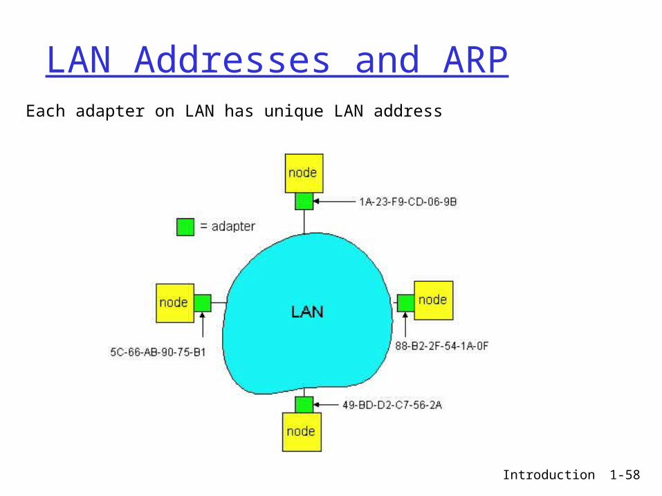
LAN Addresses and ARPEach adapter on LAN has unique LAN address
Introduction 1-59
LAN Address (more)
MAC address allocation administered by IEEE manufacturer buys portion of MAC address space (to assure
uniqueness) Analogy:
(a) MAC address: like Social Security Number
(b) IP address: like postal address MAC flat address => portability
can move LAN card from one LAN to another IP hierarchical address NOT portable
depends on IP network to which node is attached
Introduction 1-60
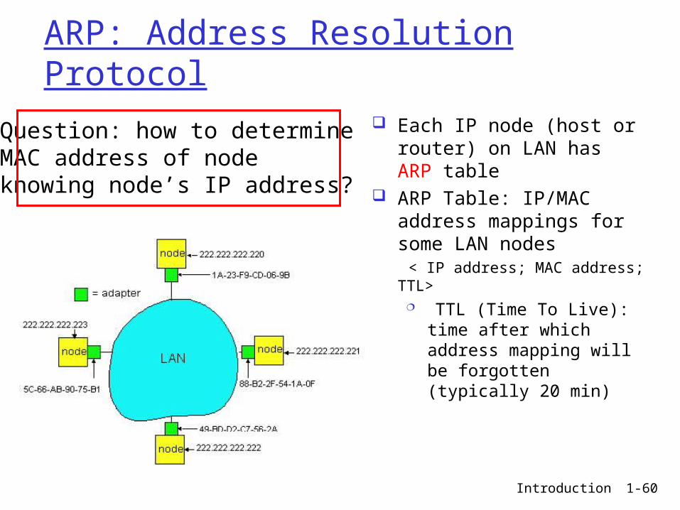
ARP: Address Resolution Protocol
Each IP node (host or router) on LAN has ARP table
ARP Table: IP/MAC address mappings for some LAN nodes
< IP address; MAC address; TTL> TTL (Time To Live): time
after which address mapping will be forgotten (typically 20 min)
Question: how to determineMAC address of nodeknowing node’s IP address?
Introduction 1-61
ARP protocol
A wants to send datagram to B, and A knows B’s IP address.
Suppose B’s MAC address is not in A’s ARP table.
A broadcasts ARP query packet, containing B's IP address all machines on LAN
receive ARP query
B receives ARP packet, replies to A with its (B's) MAC address
frame sent to A’s MAC address (unicast)
A caches (saves) IP-to-MAC address pair in its ARP table until information becomes old (times out) soft state: information
times out (goes away) unless refreshed
ARP is “plug-and-play”: nodes create their ARP
tables without intervention from net administrator
Introduction 1-62
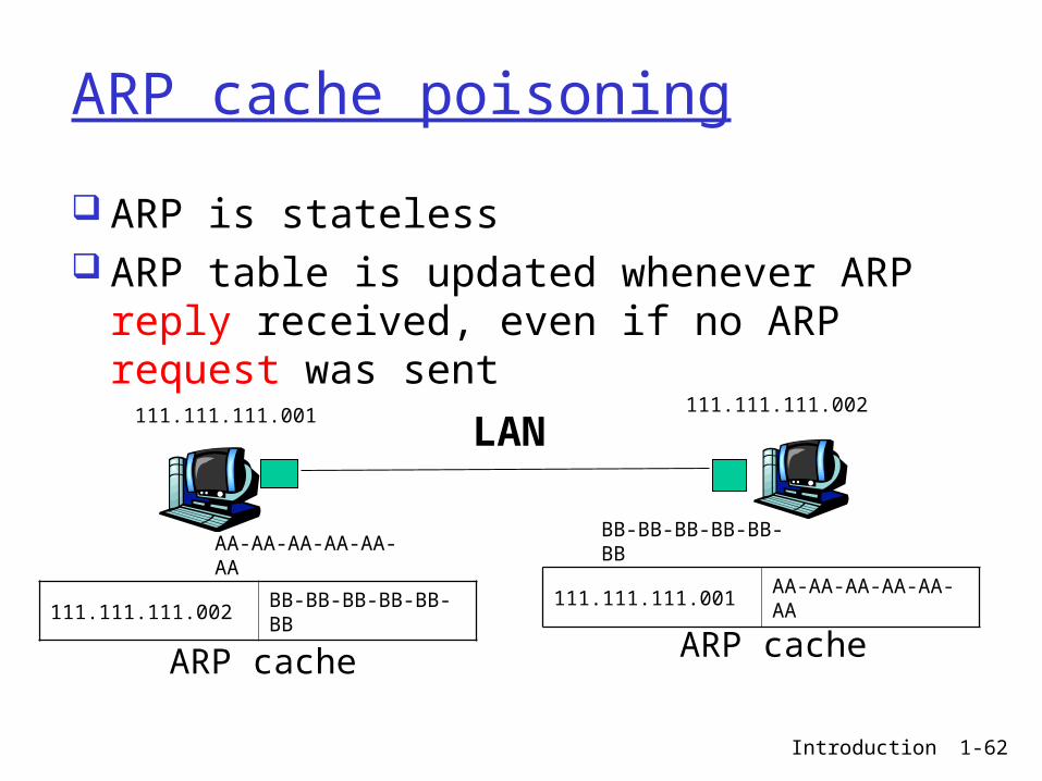
ARP cache poisoning
ARP is stateless ARP table is updated whenever ARP reply
received, even if no ARP request was sent
LAN111.111.111.001 111.111.111.002
AA-AA-AA-AA-AA-AA
BB-BB-BB-BB-BB-BB
111.111.111.002 BB-BB-BB-BB-BB-BB111.111.111.001 AA-AA-AA-AA-AA-AA
ARP cache ARP cache
Introduction 1-63
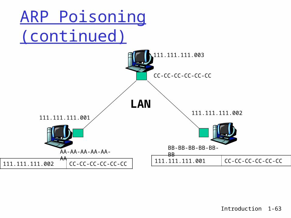
ARP Poisoning (continued)
111.111.111.003
111.111.111.002
AA-AA-AA-AA-AA-AA
BB-BB-BB-BB-BB-BB
111.111.111.002 CC-CC-CC-CC-CC-CC 111.111.111.001 CC-CC-CC-CC-CC-CC
111.111.111.001
CC-CC-CC-CC-CC-CC
LAN
Introduction 1-64
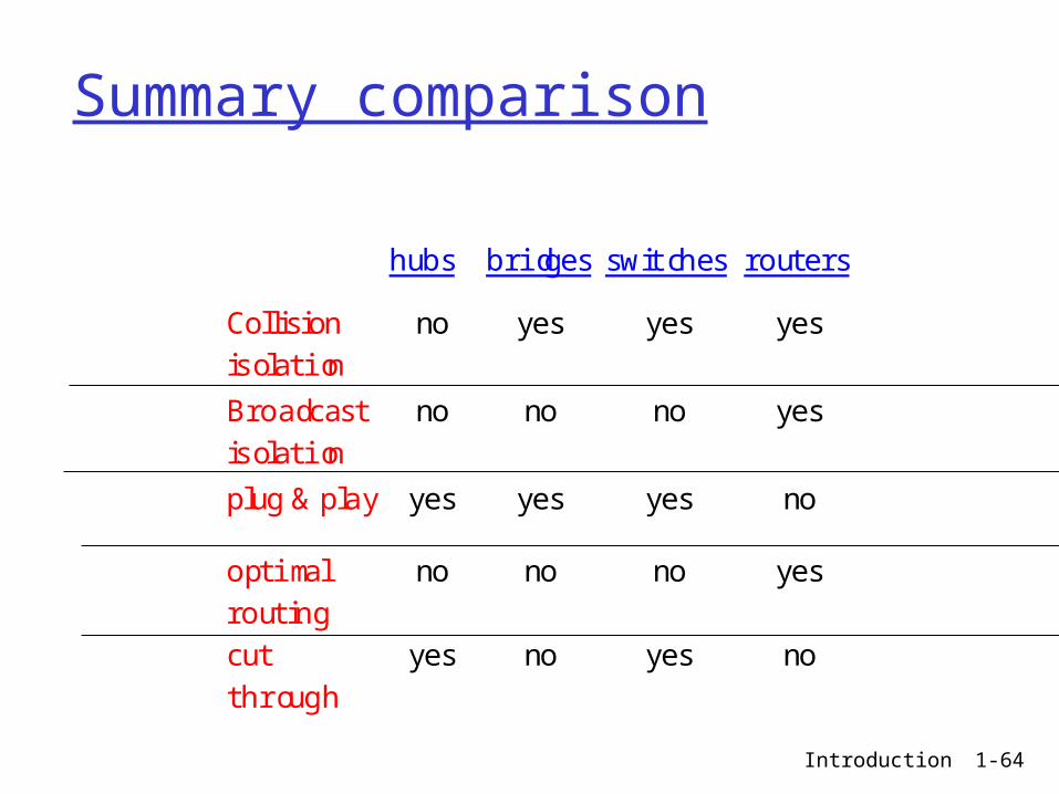
Summary comparison
hubs bridges switches routers
Collisionisolation
no yes yes yes
Broadcastisolation
no no no yes
plug & play yes yes yes no
optimalrouting
no no no yes
cutthrough
yes no yes no