Embed Size (px)
Citation preview
Overview: Networks 1-1
Overview: NetworksCPS372 Networking
Adapted from Computer Networking slides

Overview: Networks 1-2
What’s the Internet: “nuts and bolts” view
millions of connected computing devices: hosts = end systems running network apps
Home network
Institutional network
Mobile network
Global ISP
Regional ISP
router
PC
server
wirelesslaptop
cellular handheld
wiredlinks
access points
communication links fiber, copper, radio, satellite
transmission rate = bandwidth
routers: forward packets (chunks of data)
Overview: Networks 1-3
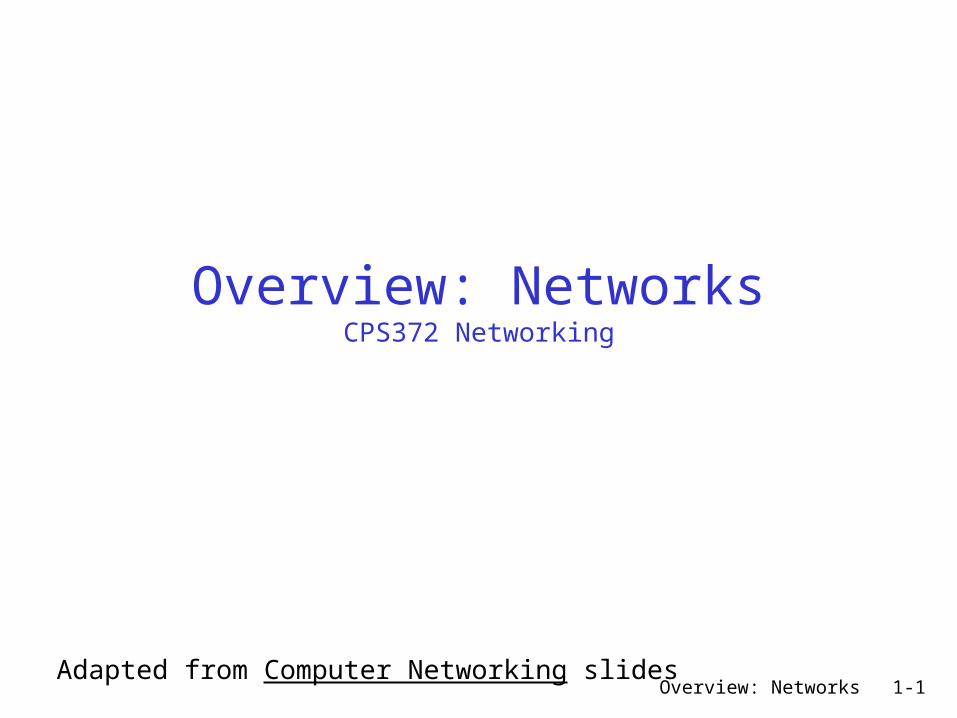
What’s the Internet: “nuts and bolts” view protocols control sending, receiving of msgs e.g., TCP, IP, HTTP, Skype, Ethernet
Internet: “network of networks” loosely hierarchical public Internet versus private intranet
Internet standards RFC: Request for comments
IETF: Internet Engineering Task Force
Home network
Institutional network
Mobile network
Global ISP
Regional ISP
Overview: Networks 1-4
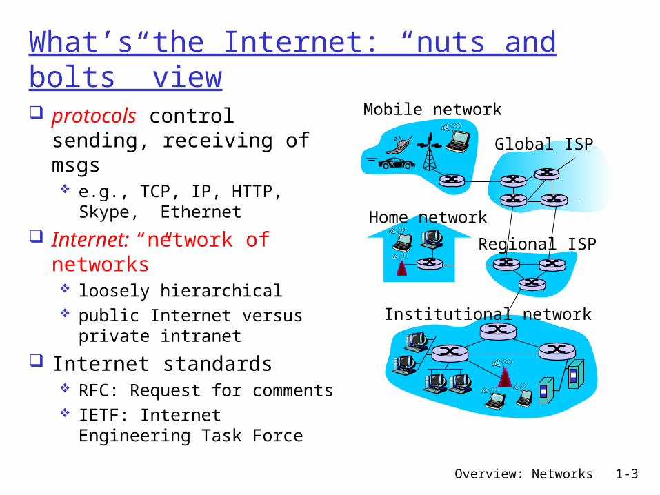
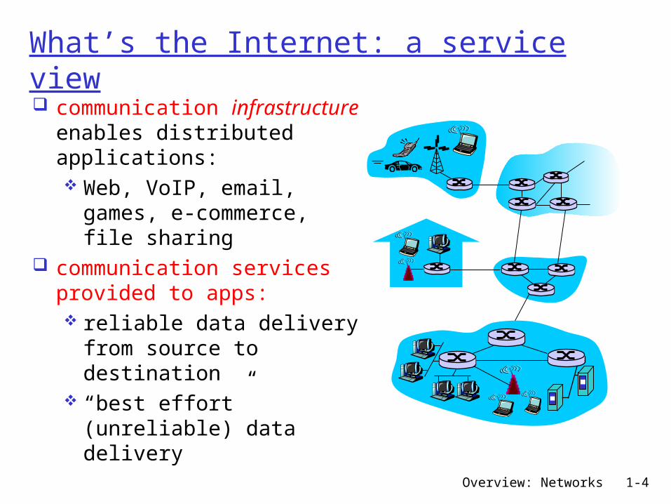
What’s the Internet: a service view communication infrastructure enables distributed applications: Web, VoIP, email, games, e-commerce, file sharing
communication services provided to apps: reliable data delivery from source to destination
“best effort” (unreliable) data delivery

Overview: Networks 1-5
What’s a protocol?network protocols:all communication activity in Internet governed by protocols
protocols define format, order of msgs sent and received among network
entities, and actions taken on msg transmission, receipt
Overview: Networks 1-6
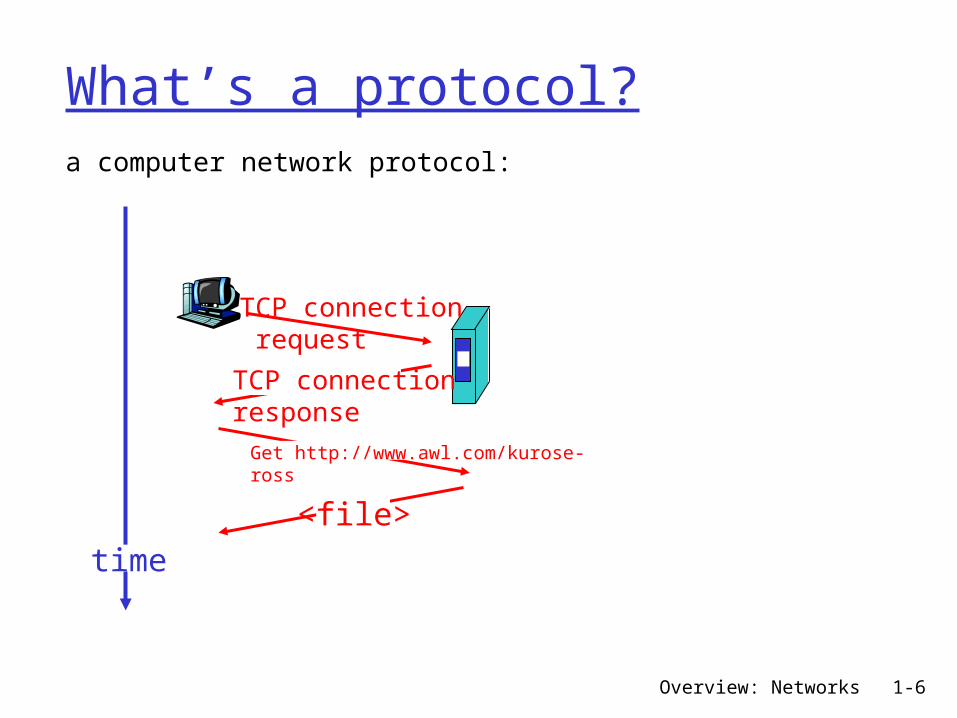
What’s a protocol?a computer network protocol:
TCP connection request
TCP connectionresponseGet http://www.awl.com/kurose-ross
<file>time

Overview: Networks 1-7
A closer look at network structure:
network edge: applications and hosts
access networks, physical media: wired, wireless communication links
network core: interconnected routers
network of networks
Overview: Networks 1-8
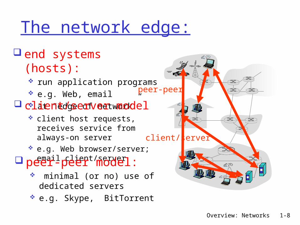
The network edge: end systems (hosts): run application programs e.g. Web, email at “edge of network”
client/server
peer-peer
client/server model client host requests, receives service from always-on server
e.g. Web browser/server; email client/server peer-peer model:
minimal (or no) use of dedicated servers
e.g. Skype, BitTorrent
Overview: Networks 1-9
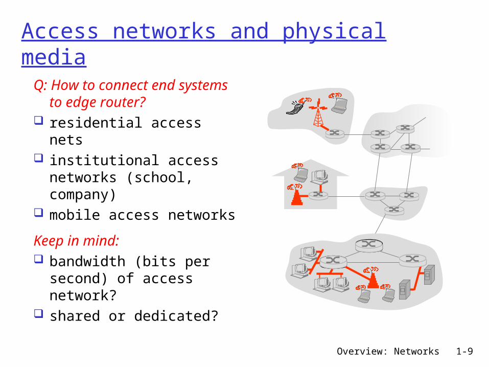
Access networks and physical mediaQ: How to connect end systems to edge router?
residential access nets
institutional access networks (school, company)
mobile access networks
Keep in mind: bandwidth (bits per second) of access network?
shared or dedicated?
Overview: Networks 1-10
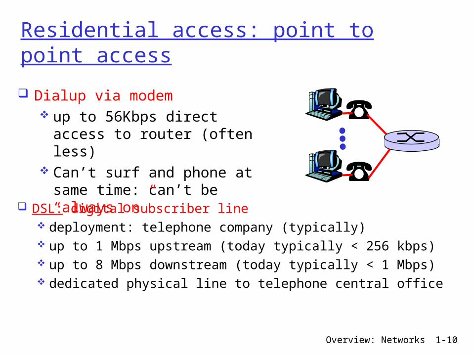
Residential access: point to point access
Dialup via modem up to 56Kbps direct access to router (often less)
Can’t surf and phone at same time: can’t be “always on” DSL: digital subscriber line
deployment: telephone company (typically) up to 1 Mbps upstream (today typically < 256 kbps) up to 8 Mbps downstream (today typically < 1 Mbps) dedicated physical line to telephone central office
Overview: Networks 1-11
Residential access: cable modems
HFC: hybrid fiber coax asymmetric: up to 30Mbps downstream, 2 Mbps upstream
network of cable and fiber attaches homes to ISP router homes share access to router
deployment: available via cable TV companies
Overview: Networks 1-12
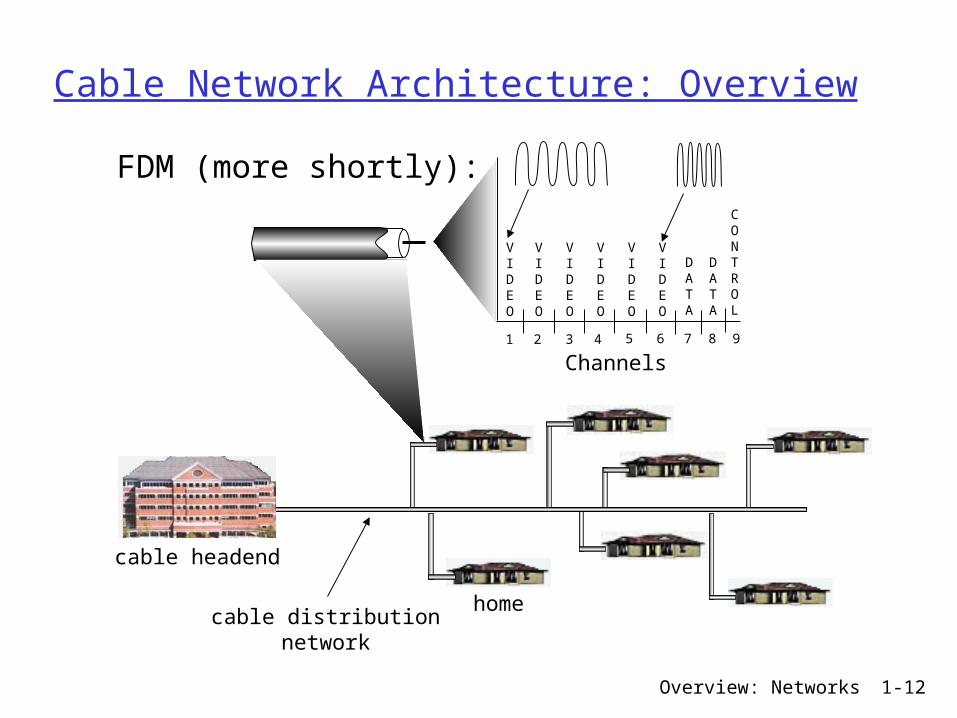
Cable Network Architecture: Overview
home
cable headend
cable distributionnetwork
Channels
VIDEO
VIDEO
VIDEO
VIDEO
VIDEO
VIDEO
DATA
DATA
CONTROL
1 2 3 4 5 6 7 8 9
FDM (more shortly):
Overview: Networks 1-13
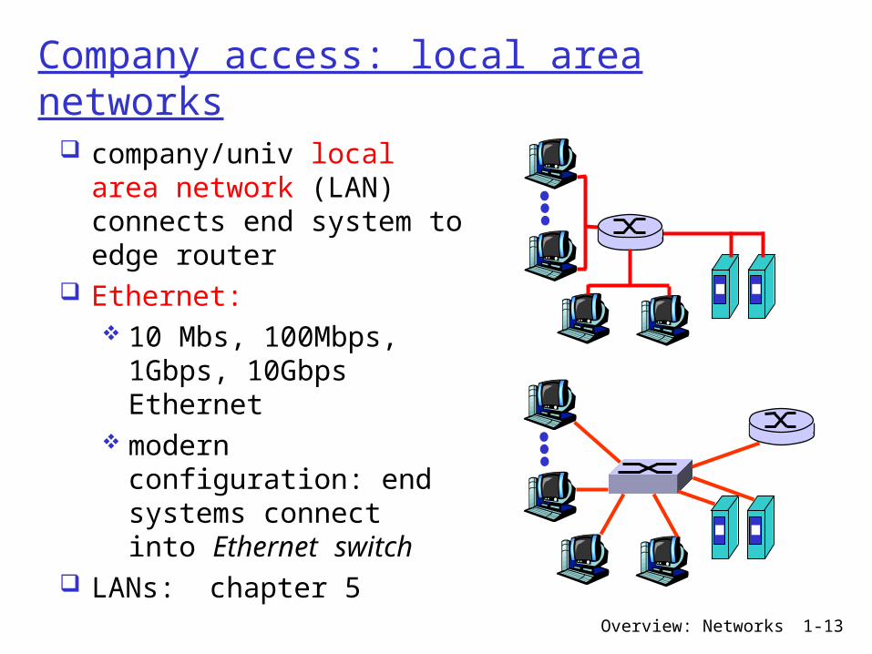
Company access: local area networks
company/univ local area network (LAN) connects end system to edge router
Ethernet: 10 Mbs, 100Mbps, 1Gbps, 10Gbps Ethernet
modern configuration: end systems connect into Ethernet switch
LANs: chapter 5

Overview: Networks 1-14
Wireless access networks
shared wireless access network connects end system to router via base station aka “access point”
wireless LANs: 802.11b/g (WiFi): 11 or 54 Mbps
wider-area wireless access provided by telco operator ~1Mbps over cellular system (EVDO, HSDPA)
next up (?): WiMAX (10’s Mbps) over wide area
basestation
mobilehosts
router

Overview: Networks 1-15
Home networks
Typical home network components: DSL or cable modem router/firewall/NAT Ethernet wireless access point
wirelessaccess point
wirelesslaptops
router/firewall
cablemodem
to/fromcable
headend
Ethernet
Overview: Networks 1-16
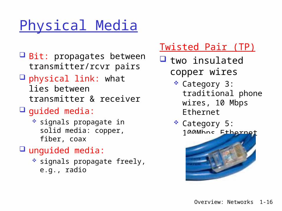
Physical Media
Bit: propagates betweentransmitter/rcvr pairs
physical link: what lies between transmitter & receiver
guided media: signals propagate in solid media: copper, fiber, coax
unguided media: signals propagate freely, e.g., radio
Twisted Pair (TP) two insulated copper wires Category 3: traditional phone wires, 10 Mbps Ethernet
Category 5: 100Mbps Ethernet
Overview: Networks 1-17
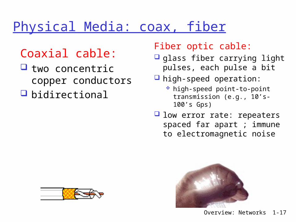
Physical Media: coax, fiber
Coaxial cable: two concentric copper conductors
bidirectional
Fiber optic cable: glass fiber carrying light pulses, each pulse a bit
high-speed operation: high-speed point-to-point transmission (e.g., 10’s-100’s Gps)
low error rate: repeaters spaced far apart ; immune to electromagnetic noise
Overview: Networks 1-18
Physical media: radio
signal carried in electromagnetic spectrum
no physical “wire” bidirectional propagation environment effects: reflection obstruction by objects
interference
Radio link types: terrestrial microwave
e.g. up to 45 Mbps channels
LAN (e.g., Wifi) 11Mbps, 54 Mbps
wide-area (e.g., cellular) 3G cellular: ~ 1 Mbps
satellite Kbps to 45Mbps channel (or multiple smaller channels)
270 msec end-end delay geosynchronous versus low altitude
Overview: Networks 1-19
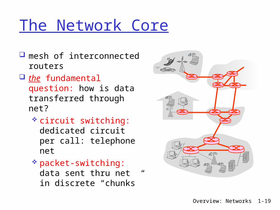
The Network Core
mesh of interconnected routers
the fundamental question: how is data transferred through net? circuit switching: dedicated circuit per call: telephone net
packet-switching: data sent thru net in discrete “chunks”
Overview: Networks 1-20
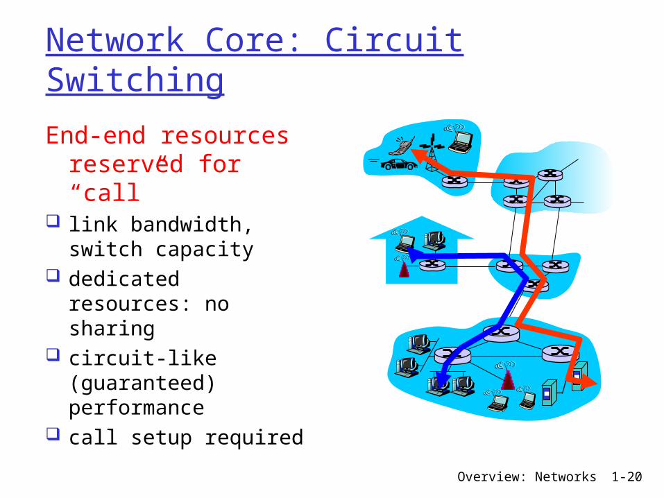
Network Core: Circuit Switching
End-end resources reserved for “call”
link bandwidth, switch capacity
dedicated resources: no sharing
circuit-like (guaranteed) performance
call setup required
Overview: Networks 1-21
Network Core: Circuit Switchingnetwork resources (e.g., bandwidth) divided into “pieces”
pieces allocated to calls resource piece idle if not used by owning call (no sharing)
dividing link bandwidth into “pieces” frequency division time division
Overview: Networks 1-22
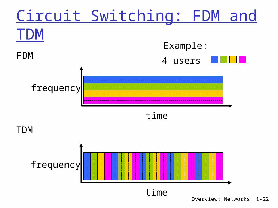
Circuit Switching: FDM and TDMFDM
frequency
time
TDM
frequency
time
4 users
Example:
Overview: Networks 1-23
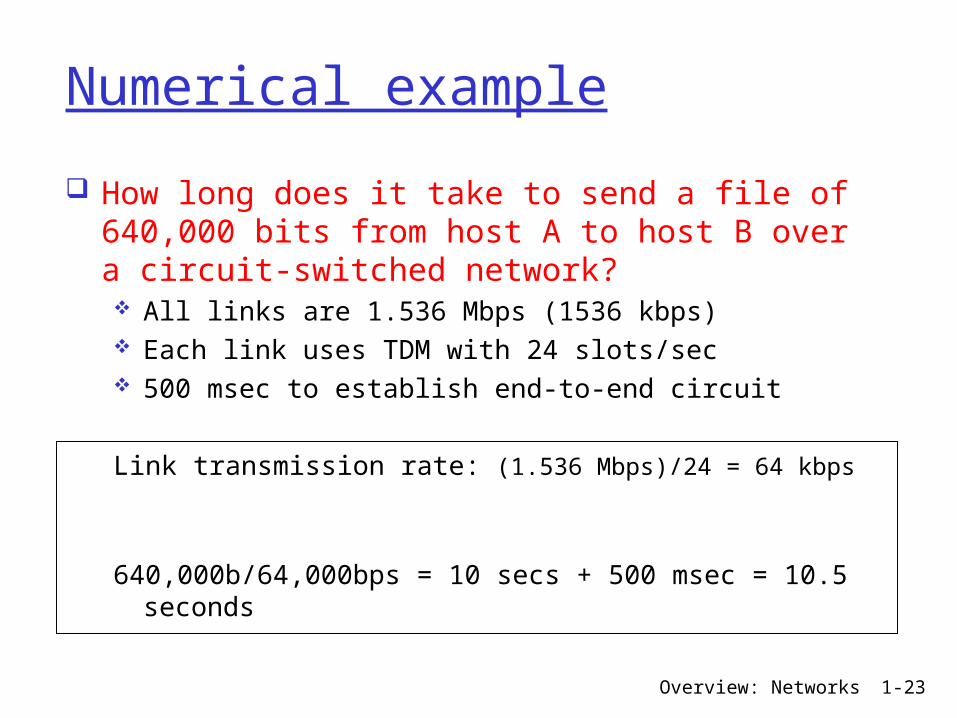
Numerical example
How long does it take to send a file of 640,000 bits from host A to host B over a circuit-switched network? All links are 1.536 Mbps (1536 kbps) Each link uses TDM with 24 slots/sec 500 msec to establish end-to-end circuit
Link transmission rate: (1.536 Mbps)/24 = 64 kbps
640,000b/64,000bps = 10 secs + 500 msec = 10.5 seconds
Overview: Networks 1-24
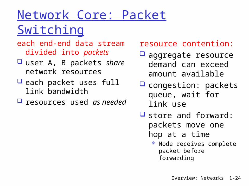
Network Core: Packet Switchingeach end-end data stream divided into packets
user A, B packets share network resources
each packet uses full link bandwidth
resources used as needed
resource contention: aggregate resource demand can exceed amount available
congestion: packets queue, wait for link use
store and forward: packets move one hop at a time Node receives
complete packet before forwarding
Overview: Networks 1-25
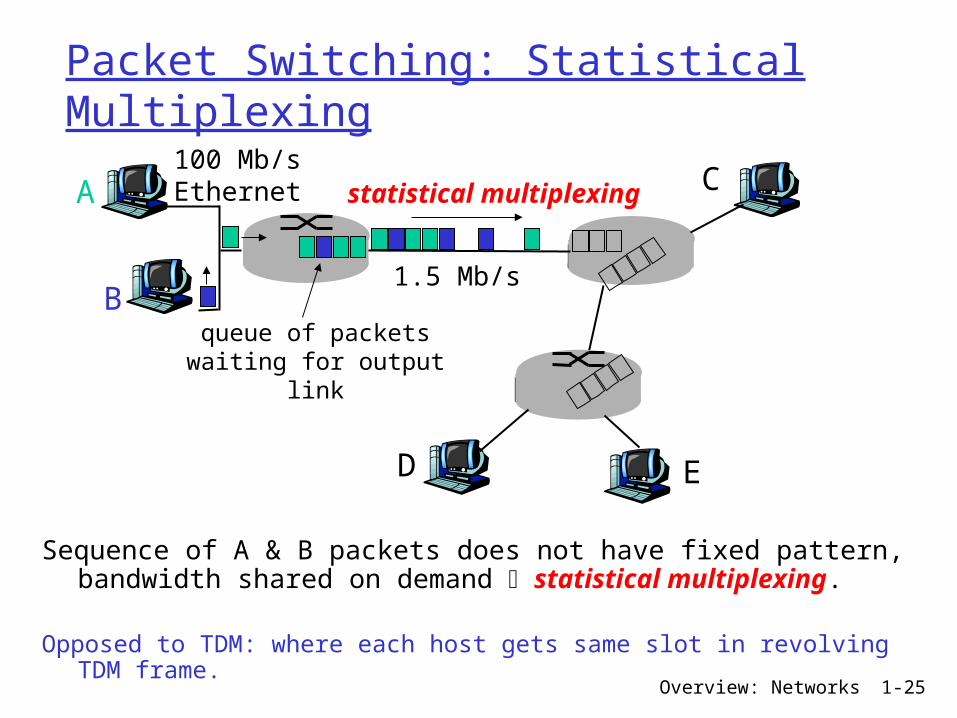
Packet Switching: Statistical Multiplexing
Sequence of A & B packets does not have fixed pattern, bandwidth shared on demand statistical multiplexing.
Opposed to TDM: where each host gets same slot in revolving TDM frame.
A
B
C100 Mb/sEthernet
1.5 Mb/s
D E
statistical multiplexing
queue of packetswaiting for output
link
Overview: Networks 1-26
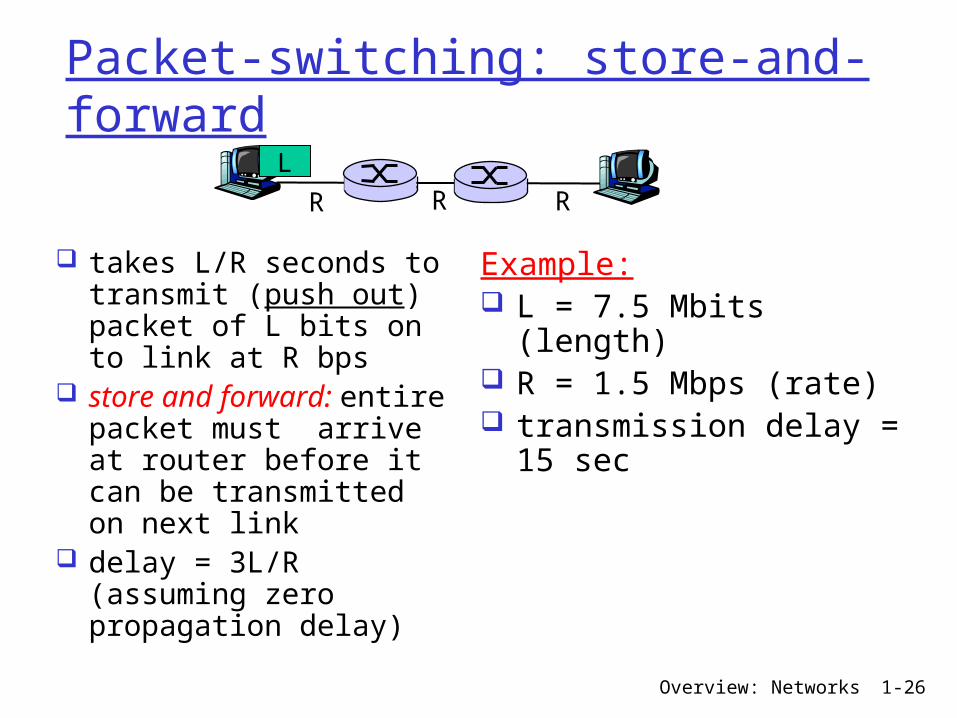
Packet-switching: store-and-forward
takes L/R seconds to transmit (push out) packet of L bits on to link at R bps
store and forward: entire packet must arrive at router before it can be transmitted on next link
delay = 3L/R (assuming zero propagation delay)
Example: L = 7.5 Mbits (length)
R = 1.5 Mbps (rate) transmission delay = 15 sec
R R RL
Overview: Networks 1-27
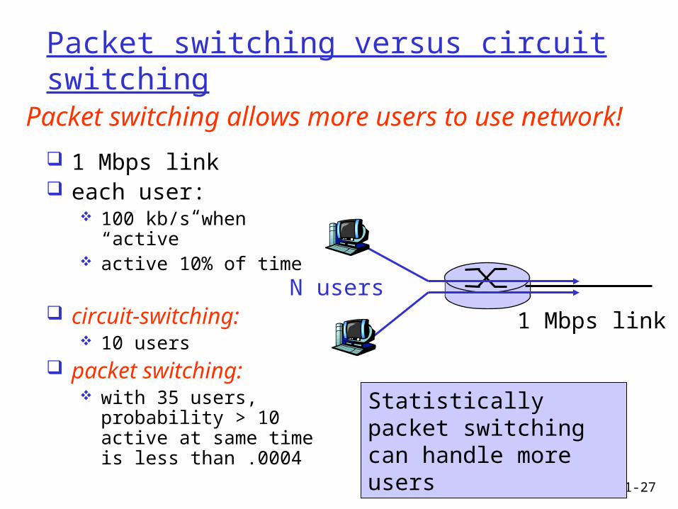
Packet switching versus circuit switching
1 Mbps link each user:
100 kb/s when “active”
active 10% of time
circuit-switching: 10 users
packet switching: with 35 users, probability > 10 active at same time is less than .0004
Packet switching allows more users to use network!
N users
1 Mbps link
Statistically packet switching can handle more users
Overview: Networks 1-28
Packet switching versus circuit switching
great for bursty data resource sharing simpler, no call setup
excessive congestion: packet delay and loss protocols needed for reliable data transfer, congestion control
Q: How to provide circuit-like behavior? bandwidth guarantees needed for audio/video apps
still an unsolved problem
packet switching

Overview: Networks 1-29
Internet structure: network of networks
roughly hierarchical at center: “tier-1” ISPs (e.g., Verizon, Sprint, AT&T, Cable and Wireless), national/international coverage treat each other as equals
Tier 1 ISP
Tier 1 ISP
Tier 1 ISP
Tier-1 providers interconnect (peer) privately
Overview: Networks 1-30
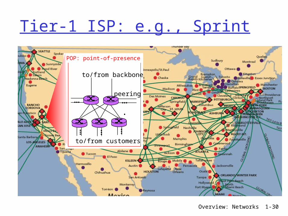
Tier-1 ISP: e.g., Sprint
…
to/from customers
peering
to/from backbone
….
………
POP: point-of-presence

Overview: Networks 1-31
Internet structure: network of networks
“Tier-2” ISPs: smaller (often regional) ISPs Connect to one or more tier-1 ISPs, possibly other tier-2 ISPs
Tier 1 ISP
Tier 1 ISP
Tier 1 ISP
Tier-2 ISPTier-2 ISP
Tier-2 ISP Tier-2 ISP
Tier-2 ISP
Tier-2 ISP (customer) pays tier-1 ISP (vendor) for connectivity to rest of Internet
Tier-2 ISPs also peer with each other.
Overview: Networks 1-32
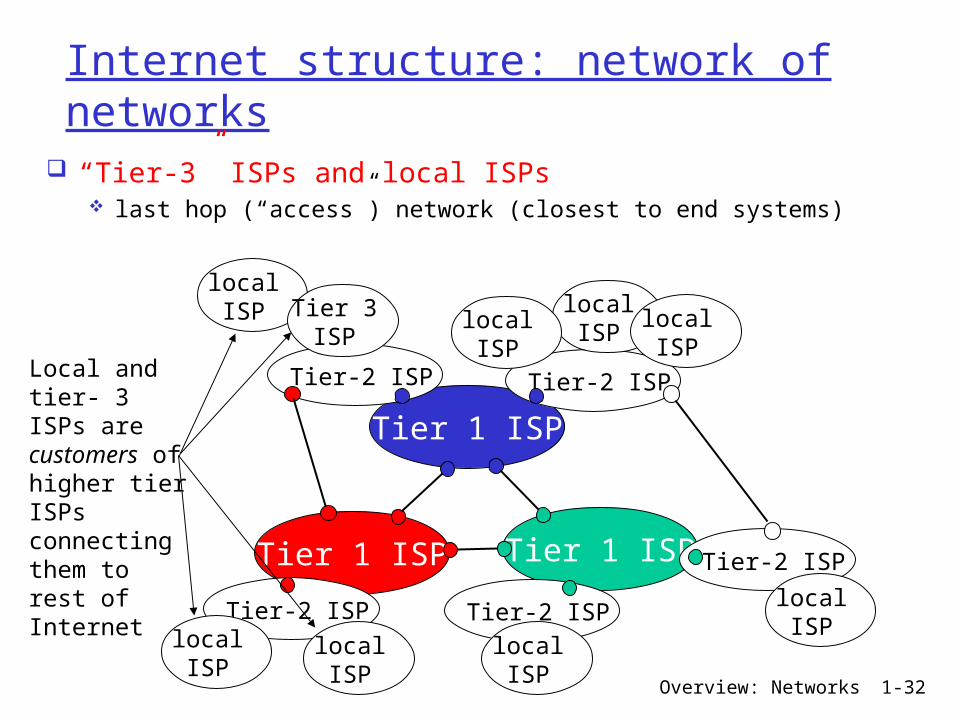
Internet structure: network of networks
“Tier-3” ISPs and local ISPs last hop (“access”) network (closest to end systems)
Tier 1 ISP
Tier 1 ISP
Tier 1 ISP
Tier-2 ISPTier-2 ISP
Tier-2 ISP Tier-2 ISP
Tier-2 ISP
localISPlocal
ISPlocalISP
localISP
localISP Tier 3
ISP
localISP
localISP
localISP
Local and tier- 3 ISPs are customers ofhigher tier ISPsconnecting them to rest of Internet
Overview: Networks 1-33
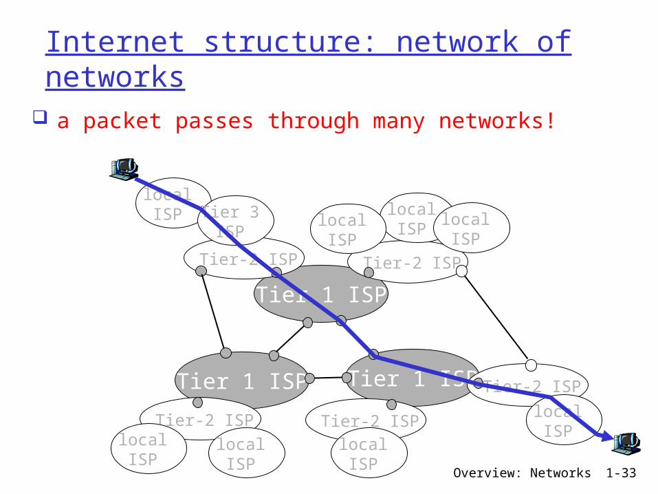
Internet structure: network of networks
a packet passes through many networks!
Tier 1 ISP
Tier 1 ISP
Tier 1 ISP
Tier-2 ISPTier-2 ISP
Tier-2 ISP Tier-2 ISP
Tier-2 ISP
localISPlocal
ISPlocalISP
localISP
localISP Tier 3
ISP
localISP
localISP
localISP
Overview: Networks 1-34
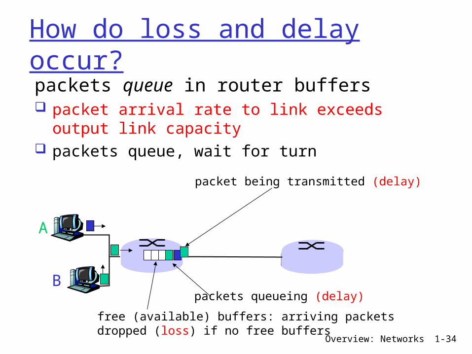
How do loss and delay occur?packets queue in router buffers packet arrival rate to link exceeds output link capacity
packets queue, wait for turn
A
B
packet being transmitted (delay)
packets queueing (delay)
free (available) buffers: arriving packets dropped (loss) if no free buffers
Overview: Networks 1-35
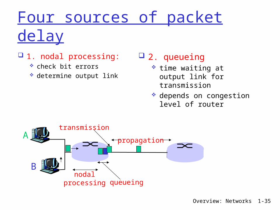
Four sources of packet delay 1. nodal processing:
check bit errors determine output link
A
B
propagation
transmission
nodalprocessing queueing
2. queueing time waiting at output link for transmission
depends on congestion level of router
Overview: Networks 1-36
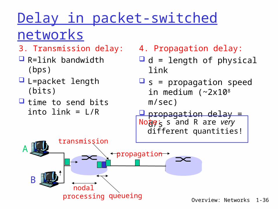
Delay in packet-switched networks3. Transmission delay: R=link bandwidth (bps)
L=packet length (bits)
time to send bits into link = L/R
4. Propagation delay: d = length of physical link
s = propagation speed in medium (~2x10⁸ m/sec)
propagation delay = d/s
A
B
propagation
transmission
nodalprocessing queueing
Note: s and R are very different quantities!

Overview: Networks 1-37
Caravan analogy
cars “propagate” at 100 km/hr
toll booth takes 12 sec to service car (transmission time)
car~bit; caravan ~ packet
Q: How long until caravan is lined up at 2nd toll booth?
Time to “push” entire caravan through toll booth onto highway = 12*10 = 120 sec
Time for last car to propagate from 1st to 2nd toll both: 100km/(100km/hr)= 1 hr
A: 62 minutes
toll booth
toll booth
ten-car caravan
100 km
100 km
Overview: Networks 1-38
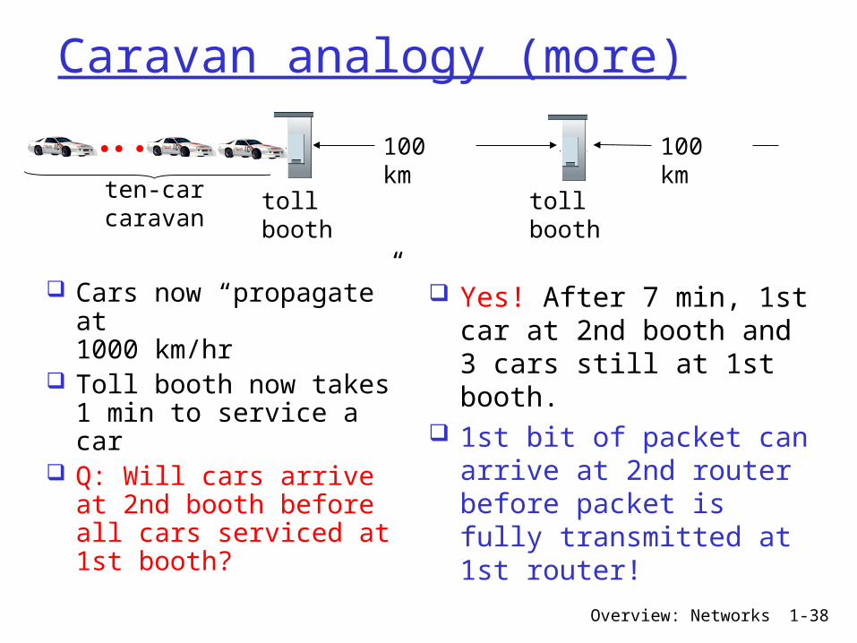
Caravan analogy (more)
Cars now “propagate” at 1000 km/hr
Toll booth now takes 1 min to service a car
Q: Will cars arrive at 2nd booth before all cars serviced at 1st booth?
Yes! After 7 min, 1st car at 2nd booth and 3 cars still at 1st booth.
1st bit of packet can arrive at 2nd router before packet is fully transmitted at 1st router!
toll booth
toll booth
ten-car caravan
100 km
100 km
Overview: Networks 1-39
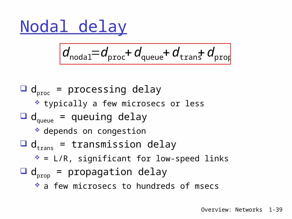
Nodal delay
dproc = processing delay typically a few microsecs or less
dqueue = queuing delay depends on congestion
dtrans = transmission delay = L/R, significant for low-speed links
dprop = propagation delay a few microsecs to hundreds of msecs
proptransqueueprocnodal ddddd +++=
Overview: Networks 1-40
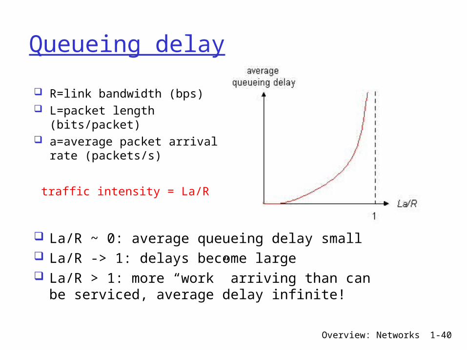
Queueing delay
R=link bandwidth (bps) L=packet length
(bits/packet) a=average packet arrival
rate (packets/s)
traffic intensity = La/R
La/R ~ 0: average queueing delay small La/R -> 1: delays become large La/R > 1: more “work” arriving than can be serviced, average delay infinite!
Overview: Networks 1-41
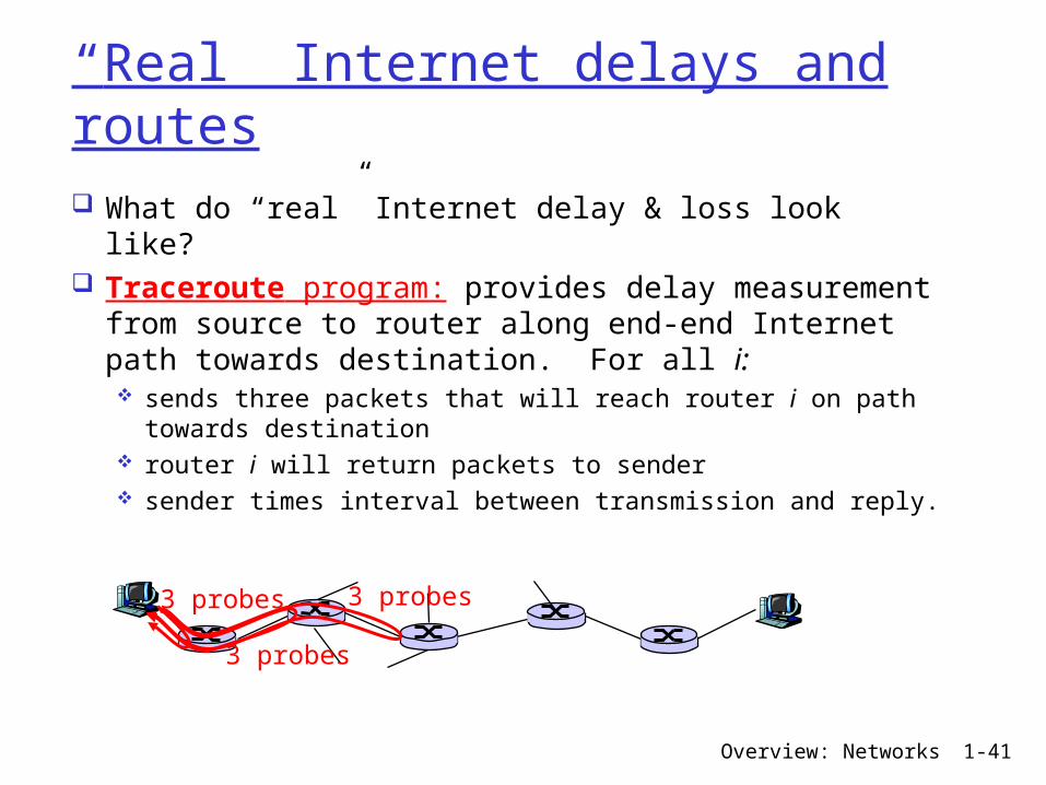
“Real” Internet delays and routes What do “real” Internet delay & loss look like? Traceroute program: provides delay measurement from source to router along end-end Internet path towards destination. For all i: sends three packets that will reach router i on path towards destination
router i will return packets to sender sender times interval between transmission and reply.
3 probes
3 probes
3 probes

Overview: Networks 1-42
“Real” Internet delays and routes How does traceroute work?Traceroute works by increasing the "time-to-live"
value of each successive batch of packets sent.
3 probes
3 probes
3 probes
TTL: 1 ICMP: time exceeded (type 11)
TTL: 2 ICMP: time exceeded (type 11)

Overview: Networks 1-43
“Real” Internet delays and routes
1 cs-gw (128.119.240.254) 1 ms 1 ms 2 ms2 border1-rt-fa5-1-0.gw.umass.edu (128.119.3.145) 1 ms 1 ms 2 ms3 cht-vbns.gw.umass.edu (128.119.3.130) 6 ms 5 ms 5 ms4 jn1-at1-0-0-19.wor.vbns.net (204.147.132.129) 16 ms 11 ms 13 ms 5 jn1-so7-0-0-0.wae.vbns.net (204.147.136.136) 21 ms 18 ms 18 ms 6 abilene-vbns.abilene.ucaid.edu (198.32.11.9) 22 ms 18 ms 22 ms7 nycm-wash.abilene.ucaid.edu (198.32.8.46) 22 ms 22 ms 22 ms8 62.40.103.253 (62.40.103.253) 104 ms 109 ms 106 ms9 de2-1.de1.de.geant.net (62.40.96.129) 109 ms 102 ms 104 ms10 de.fr1.fr.geant.net (62.40.96.50) 113 ms 121 ms 114 ms11 renater-gw.fr1.fr.geant.net (62.40.103.54) 112 ms 114 ms 112 ms12 nio-n2.cssi.renater.fr (193.51.206.13) 111 ms 114 ms 116 ms13 nice.cssi.renater.fr (195.220.98.102) 123 ms 125 ms 124 ms14 r3t2-nice.cssi.renater.fr (195.220.98.110) 126 ms 126 ms 124 ms15 eurecom-valbonne.r3t2.ft.net (193.48.50.54) 135 ms 128 ms 133 ms16 194.214.211.25 (194.214.211.25) 126 ms 128 ms 126 ms17 * * *18 * * *19 fantasia.eurecom.fr (193.55.113.142) 132 ms 128 ms 136 ms
traceroute: gaia.cs.umass.edu to www.eurecom.fr Three delay measurements from
gaia.cs.umass.edu to cs-gw.cs.umass.edu
* means no response (probe lost, router not replying)
trans-oceaniclink
Overview: Networks 1-44
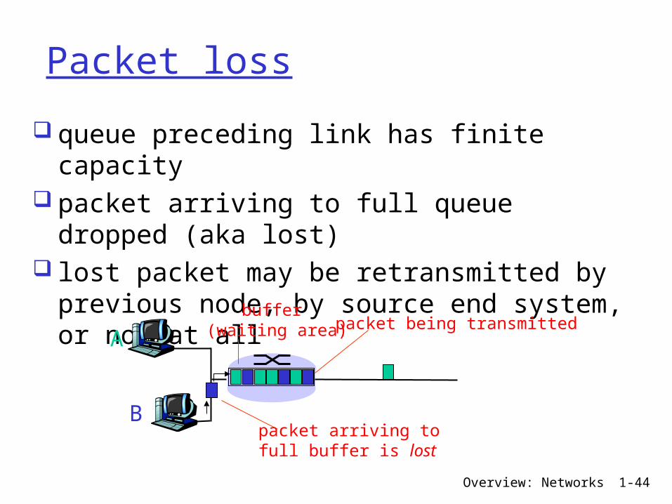
Packet loss
queue preceding link has finite capacity
packet arriving to full queue dropped (aka lost)
lost packet may be retransmitted by previous node, by source end system, or not at allA
B
packet being transmitted
packet arriving tofull buffer is lost
buffer (waiting area)
Overview: Networks 1-45
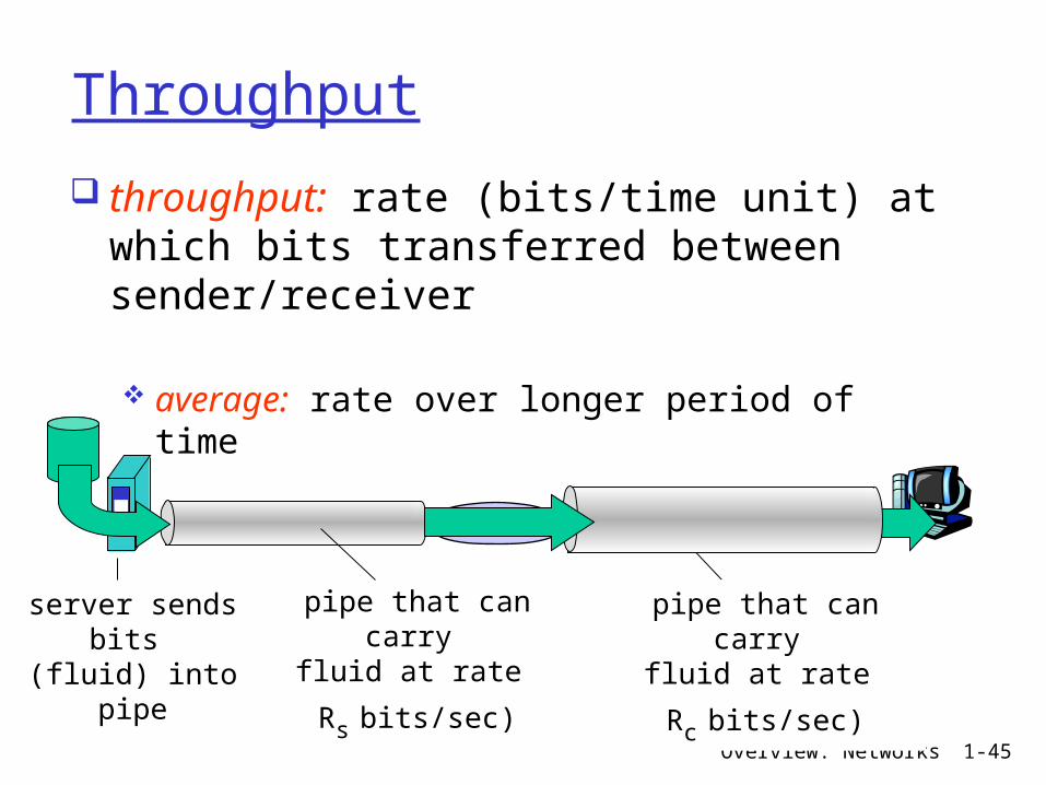
Throughput
throughput: rate (bits/time unit) at which bits transferred between sender/receiver
average: rate over longer period of time
server, withfile of F bits
to send to client
link capacity
Rs bits/sec
link capacity
Rc bits/sec pipe that can
carryfluid at rate
Rs bits/sec)
pipe that can carry
fluid at rate
Rc bits/sec)
server sends bits
(fluid) into pipe
Overview: Networks 1-46
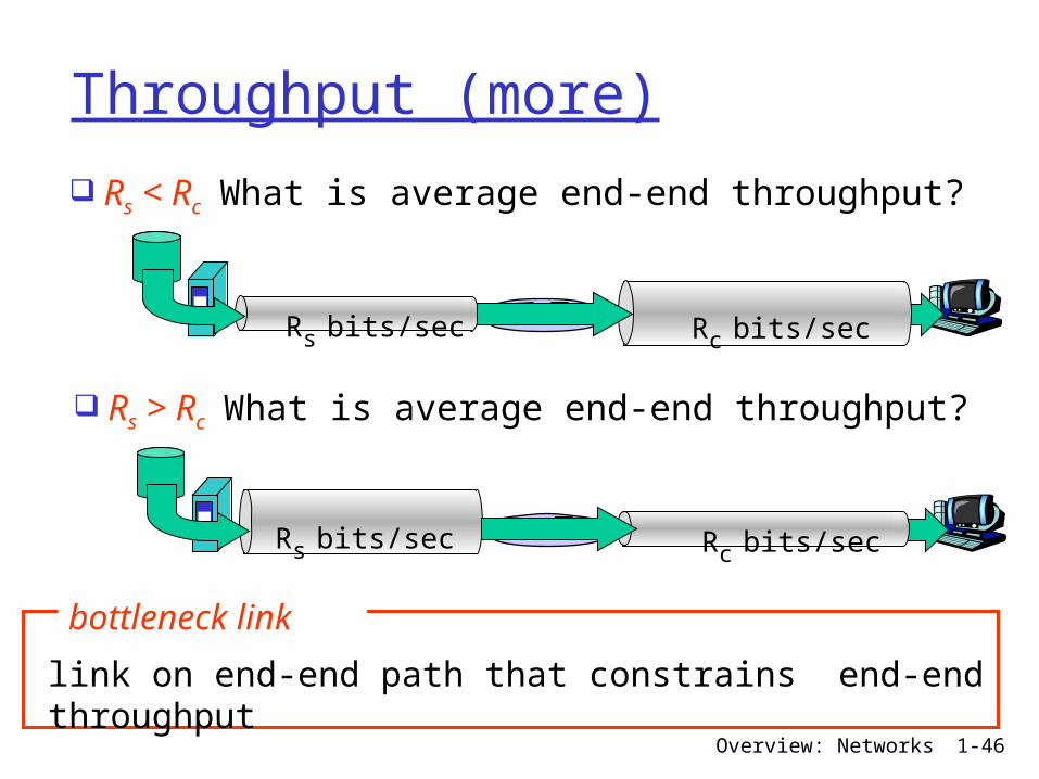
Throughput (more)
Rs < Rc What is average end-end throughput?
Rs bits/sec Rc bits/sec
Rs > Rc What is average end-end throughput?
Rs bits/sec Rc bits/sec
link on end-end path that constrains end-end throughput
bottleneck link
Overview: Networks 1-47
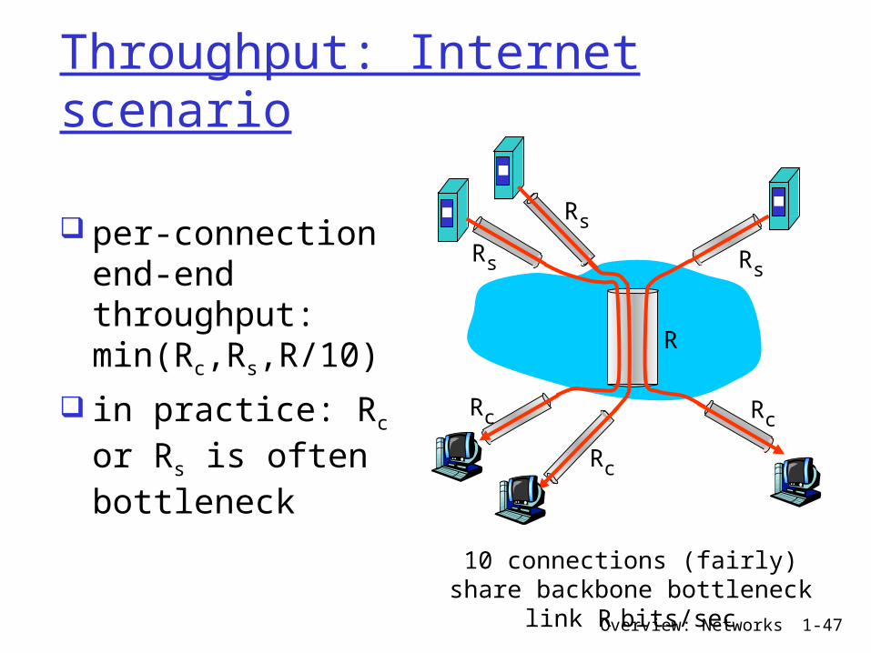
Throughput: Internet scenario
10 connections (fairly) share backbone bottleneck
link R bits/sec
Rs
Rs
Rs
Rc
Rc
Rc
R
per-connection end-end throughput: min(Rc,Rs,R/10)
in practice: Rc or Rs is often bottleneck
Overview: Networks 1-48
Protocol “Layers”Networks are complex!
many “pieces”: hosts routers links of various media
applications protocols hardware, software
Question: Is there any hope of organizing structure of
network?
Or at least our discussion of networks?
Overview: Networks 1-49
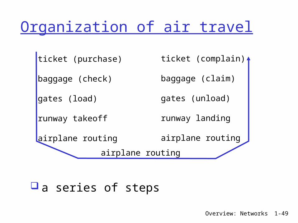
Organization of air travel
a series of steps
ticket (purchase)
baggage (check)
gates (load)
runway takeoff
airplane routing
ticket (complain)
baggage (claim)
gates (unload)
runway landing
airplane routing
airplane routing
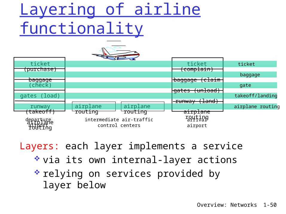
Overview: Networks 1-50
ticket (purchase)
baggage (check)
gates (load)
runway (takeoff)
airplane routing
departureairport
arrivalairport
intermediate air-trafficcontrol centers
airplane routing airplane routing
ticket (complain)
baggage (claim
gates (unload)
runway (land)
airplane routing
ticket
baggage
gate
takeoff/landing
airplane routing
Layering of airline functionality
Layers: each layer implements a service via its own internal-layer actions relying on services provided by layer below
Overview: Networks 1-51
Why layering?Dealing with complex systems: explicit structure allows identification, relationship of complex system’s pieces layered reference model for discussion
modularization eases maintenance, updating of system change of implementation of layer’s service transparent to rest of system
e.g., change in gate procedure doesn’t affect rest of system
layering considered harmful?
Overview: Networks 1-52
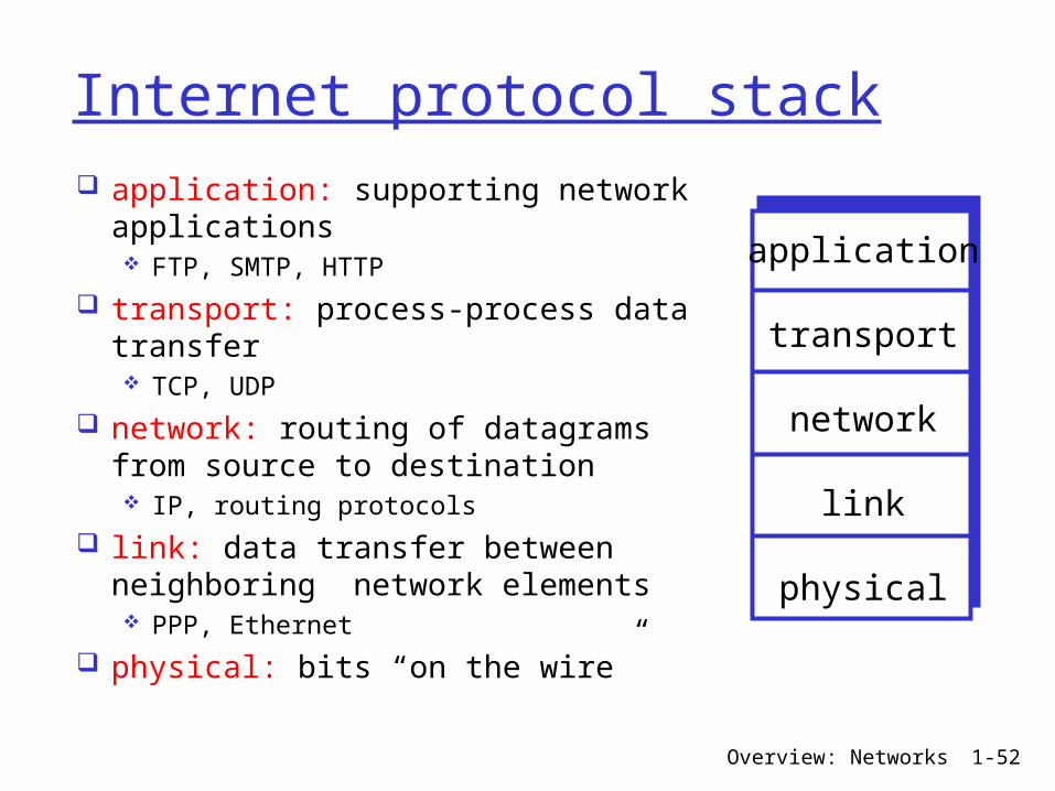
Internet protocol stack application: supporting network applications FTP, SMTP, HTTP
transport: process-process data transfer TCP, UDP
network: routing of datagrams from source to destination IP, routing protocols
link: data transfer between neighboring network elements PPP, Ethernet
physical: bits “on the wire”
application
transport
network
link
physical

Overview: Networks 1-53
ISO/OSI reference model presentation: allow applications to interpret meaning of data, e.g., encryption, compression, machine-specific conventions
session: synchronization, checkpointing, recovery of data exchange
Internet stack “missing” these layers! these services, if needed, must be implemented in application
needed?
application
presentation
session
transport
network
link
physical

Overview: Networks 1-54
sourceapplicat
iontranspor
tnetworklink
physical
HtHn M
segment Ht
datagram
destination
application
transport
networklink
physical
HtHnHl M
HtHn M
Ht M
M
networklink
physical
linkphysical
HtHnHl M
HtHn M
HtHn M
HtHnHl M
router
switch
Encapsulationmessage M
Ht M
Hnframe
Overview: Networks 1-55
Network Security The field of network security is about: how bad guys can attack computer networks how we can defend networks against attacks how to design architectures that are immune to attacks
Internet not originally designed with (much) security in mind original vision: “a group of mutually trusting users attached to a transparent network”
Internet protocol designers playing “catch-up”
Security considerations in all layers!
Overview: Networks 1-56
Bad guys can put malware into hosts via Internet Malware can get in host from a virus, worm, or trojan horse.
Spyware malware can record keystrokes, web sites visited, upload info to collection site.
Infected host can be enrolled in a botnet, used for spam and DDoS attacks.
Malware is often self-replicating: from an infected host, seeks entry into other hosts
Overview: Networks 1-57
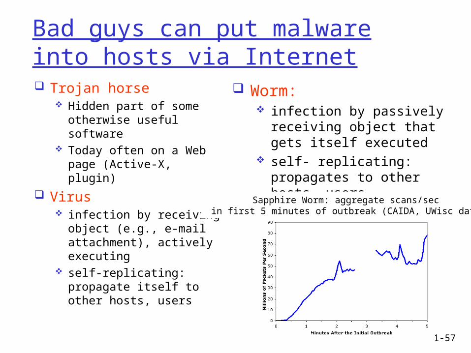
Bad guys can put malware into hosts via Internet Trojan horse
Hidden part of some otherwise useful software
Today often on a Web page (Active-X, plugin)
Virus infection by receiving object (e.g., e-mail attachment), actively executing
self-replicating: propagate itself to other hosts, users
Worm: infection by passively receiving object that gets itself executed
self- replicating: propagates to other hosts, usersSapphire Worm: aggregate scans/sec
in first 5 minutes of outbreak (CAIDA, UWisc data)
Overview: Networks 1-58
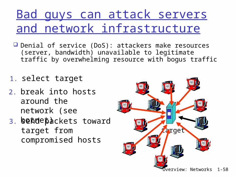
Bad guys can attack servers and network infrastructure
Denial of service (DoS): attackers make resources (server, bandwidth) unavailable to legitimate traffic by overwhelming resource with bogus traffic
1. select target
2. break into hosts around the network (see botnet)3. send packets toward target from compromised hosts
target
Overview: Networks 1-59
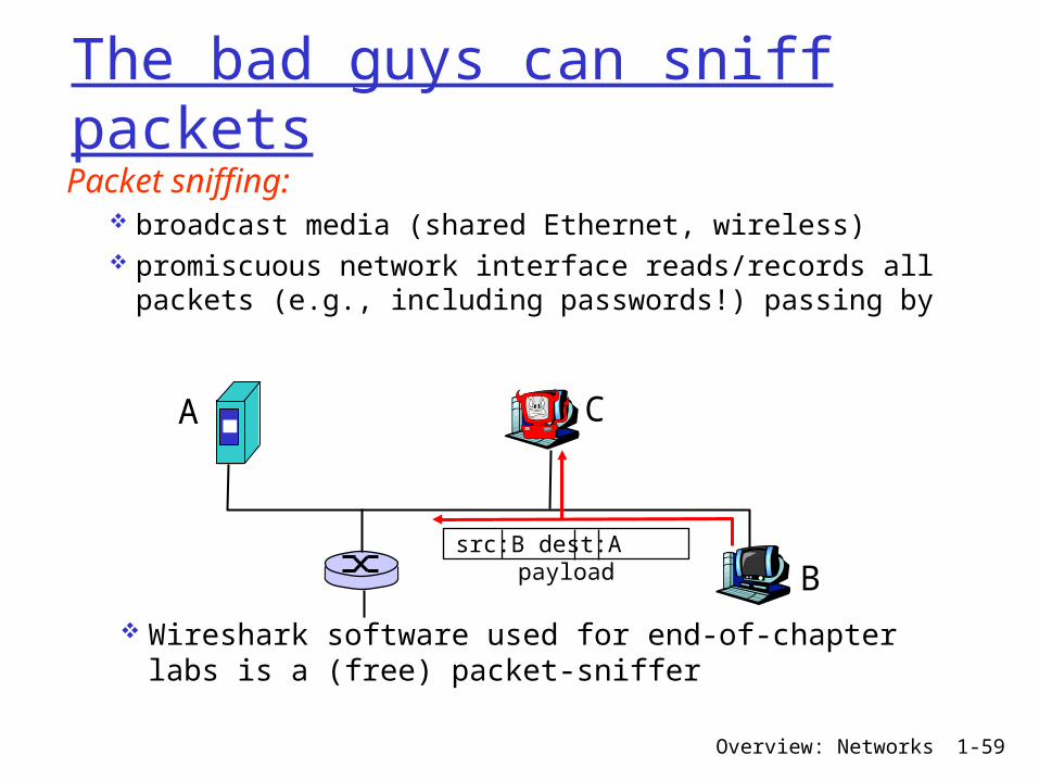
The bad guys can sniff packetsPacket sniffing:
broadcast media (shared Ethernet, wireless) promiscuous network interface reads/records all packets (e.g., including passwords!) passing by
A
B
C
src:B dest:A payload
Wireshark software used for end-of-chapter labs is a (free) packet-sniffer

Overview: Networks 1-60
The bad guys can use false source addresses IP spoofing: send packet with false source address
A
B
C
src:B dest:A payload
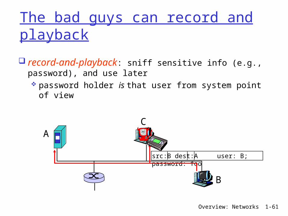
Overview: Networks 1-61
The bad guys can record and playback
record-and-playback: sniff sensitive info (e.g., password), and use later password holder is that user from system point of view
A
B
C
src:B dest:A user: B; password: foo