Embed Size (px)
Citation preview
Introduction to Parametric Drafting in AutoCAD 2012 John R. Bordeau – Kankakee Community College
AC4772 Parametric drafting tools allow you to assign parameters or constraints to objects. The
parametric concept, also known as intelligence, provides a way to associate objects and limit design changes. You cannot change a constraint so that it conflicts with other parametric geometry. A database stores and allows you to manage all parameters. You typically use parametric tools with standard drafting practices to create a more interactive drawing. In this class, we will cover how to create and edit parametric drawings, add and manage geometric and dimensional constraints, and adjust the form of dimensional constraints.
Learning Objectives At the end of this class, you will be able to:
Create and edit parametric drawings
Add and manage geometric constraints
Add and manage dimensional constraints
Adjust the form of dimensional constraints
About the Speaker
John is a professor at Kankakee Community College. He has 15 years of CAD teaching experience at universities and colleges. His professional experience covers the span of 30 years, including 13 years of expertise in managing all aspects of the CAD function for large organizations with multiple engineering disciplines, and remote offices such as AECOM and STS Consultants. John’s four main areas of specialization include CAD management and education, information technology, training and performance improvement, and industrial technology. His education includes an MS in training and organizational development from Northern Michigan University. The research project for his master's degree was "AutoCAD® E-Learning Objects for the Adult Learner." Additionally, he has a BS in industrial technology and applied sciences with a minor in CAD.
Introduction to Parametric Drafting in AutoCAD 2012
2
PARAMETRIC OVERVIEW Parametric drafting tools allow you to assign parameters, or constraints, to objects. The
parametric concept, also known as intelligence, provides a way to associate objects and limit
design changes. You cannot change a constraint so that it conflicts with other parametric
geometry. A database stores and allows you to manage all parameters. You typically use
parametric tools with standard drafting practices to create a more interactive drawing.
PARAMETRIC FUNDAMENTALS Parametric drafting can increase your ability to control every aspect of a drawing during and
after the design and documentation process. Parametric tools can change the way you
construct and edit geometry. However, in general, use parametric tools as a supplement to
standard drafting practices and drawing aids. When used correctly, this technique allows you to
produce accurate parametric drawings efficiently.
Understanding Constraints
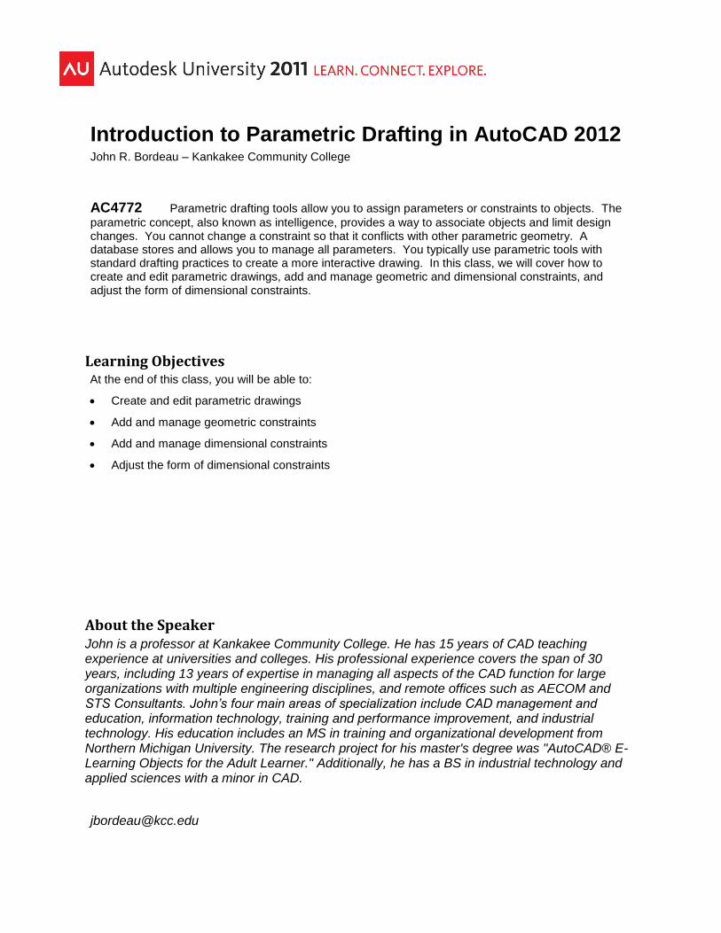
Add parameters using geometric constraints and dimensional constraints. Well-defined
constraints allow you to incorporate and preserve specific design intentions and increase
revision efficiency. For example, if two holes through a part, drawn as circles, must always be
the same size, use a geometric constraint to make the circles equal and add a dimensional
constraint to size one of the circles. The size of both circles changes when you modify the
dimensional constraint value. See Figure 1.
Introduction to Parametric Drafting in AutoCAD 2012
3
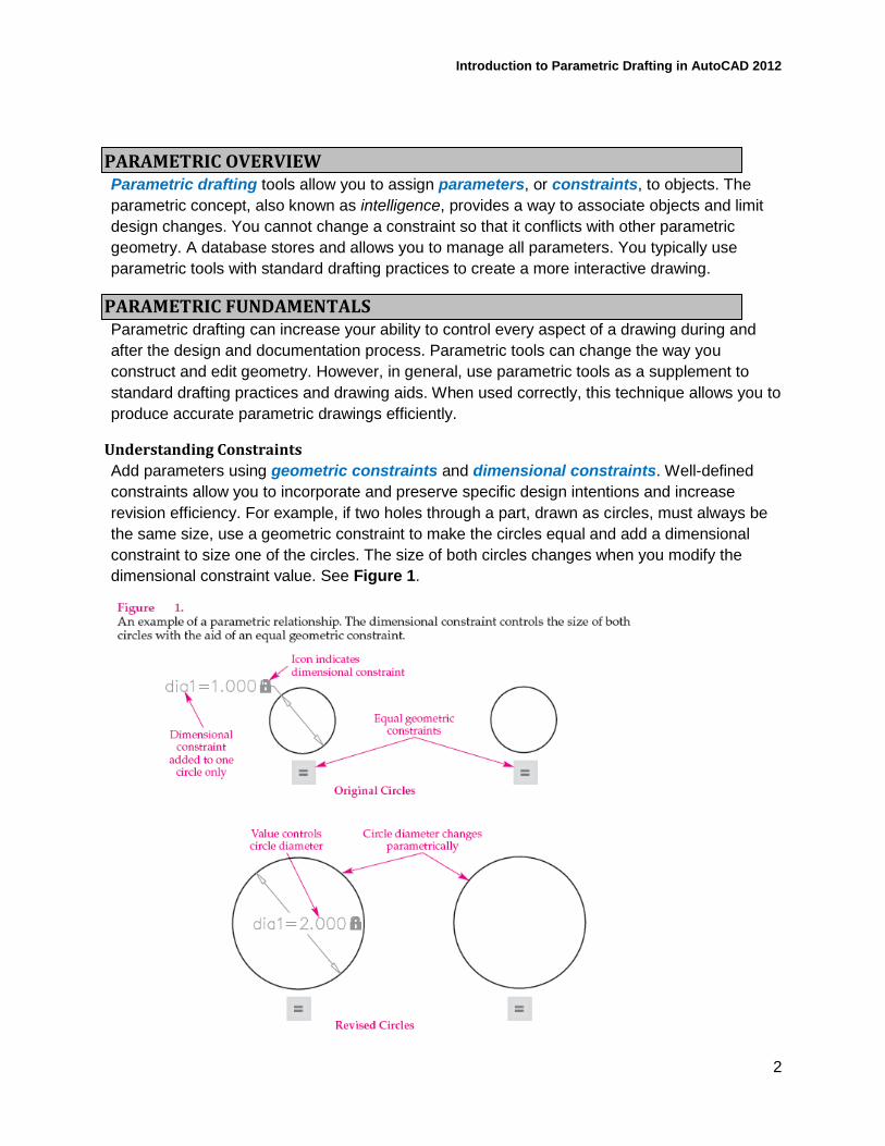
You must add constraints to make an object parametric. Dimensional constraints create
parameters that direct object size and location. In contrast, an associative dimension is
associated with an object, but it does not control object size or location. Figure 2 shows an
example of a drawing that is under-constrained, fully constrained, and over-constrained.
As you progress through the design process, you will often fully or almost fully constrain the
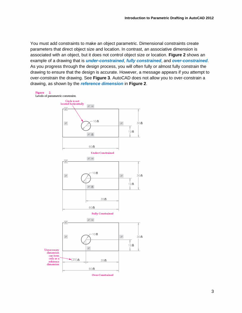
drawing to ensure that the design is accurate. However, a message appears if you attempt to
over-constrain the drawing. See Figure 3. AutoCAD does not allow you to over-constrain a
drawing, as shown by the reference dimension in Figure 2.
Introduction to Parametric Drafting in AutoCAD 2012
4
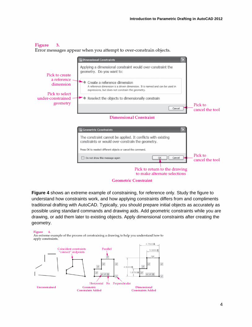
Figure 4 shows an extreme example of constraining, for reference only. Study the figure to
understand how constraints work, and how applying constraints differs from and compliments
traditional drafting with AutoCAD. Typically, you should prepare initial objects as accurately as
possible using standard commands and drawing aids. Add geometric constraints while you are
drawing, or add them later to existing objects. Apply dimensional constraints after creating the
geometry.
Introduction to Parametric Drafting in AutoCAD 2012
5
Parametric Applications
Parametric tools aid the design and revision process, place limits on geometry to preserve
design intent, and help form geometric constructions. Consider using constraints to help
maintain relationships between objects in a drawing, especially during the design process,
when changes are often frequent. However, you must decide if the additional steps required to
make a drawing parametric are appropriate and necessary for the application.
Product Design and Revision
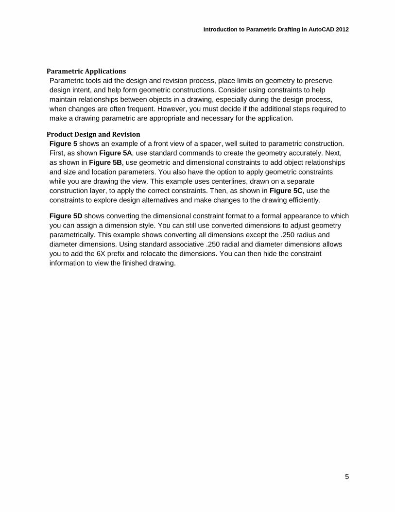
Figure 5 shows an example of a front view of a spacer, well suited to parametric construction.
First, as shown Figure 5A, use standard commands to create the geometry accurately. Next,
as shown in Figure 5B, use geometric and dimensional constraints to add object relationships
and size and location parameters. You also have the option to apply geometric constraints
while you are drawing the view. This example uses centerlines, drawn on a separate
construction layer, to apply the correct constraints. Then, as shown in Figure 5C, use the
constraints to explore design alternatives and make changes to the drawing efficiently.
Figure 5D shows converting the dimensional constraint format to a formal appearance to which
you can assign a dimension style. You can still use converted dimensions to adjust geometry
parametrically. This example shows converting all dimensions except the .250 radius and
diameter dimensions. Using standard associative .250 radial and diameter dimensions allows
you to add the 6X prefix and relocate the dimensions. You can then hide the constraint
information to view the finished drawing.
Introduction to Parametric Drafting in AutoCAD 2012
6
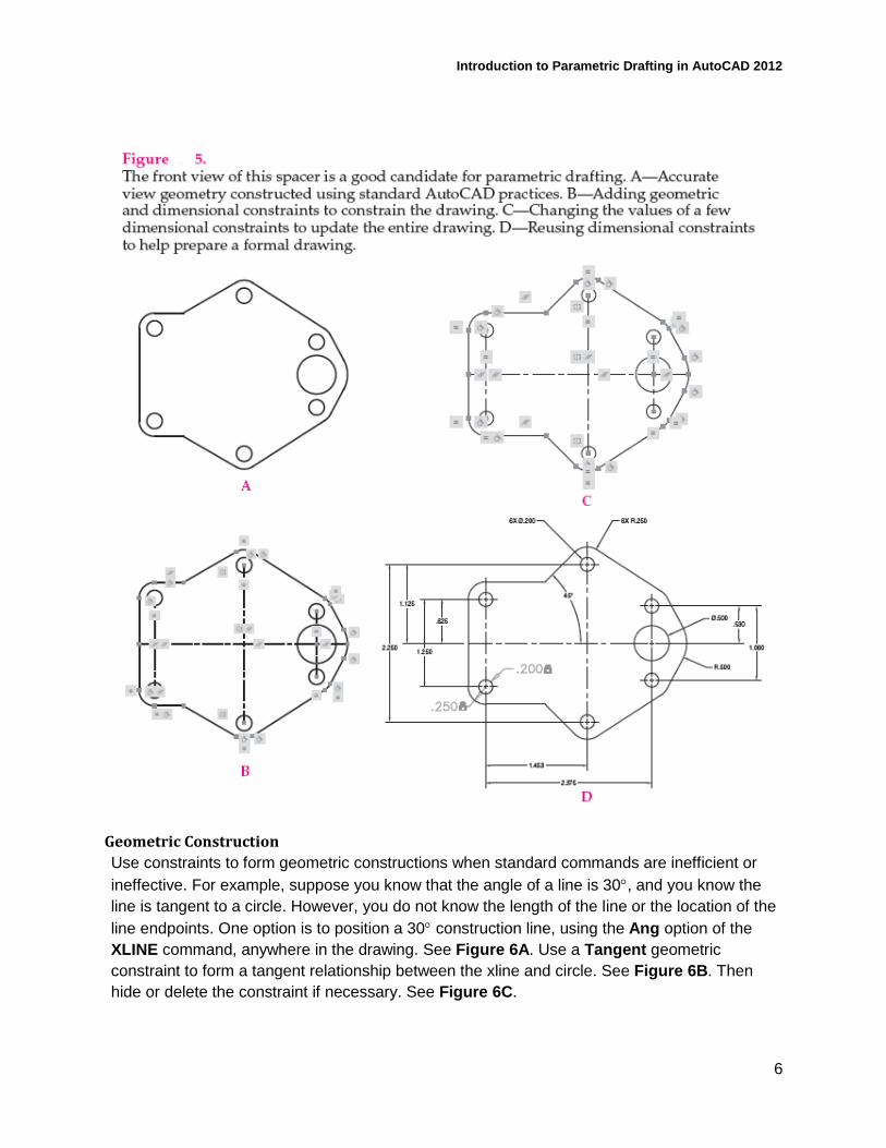
Geometric Construction
Use constraints to form geometric constructions when standard commands are inefficient or
ineffective. For example, suppose you know that the angle of a line is 30, and you know the
line is tangent to a circle. However, you do not know the length of the line or the location of the
line endpoints. One option is to position a 30 construction line, using the Ang option of the
XLINE command, anywhere in the drawing. See Figure 6A. Use a Tangent geometric
constraint to form a tangent relationship between the xline and circle. See Figure 6B. Then
hide or delete the constraint if necessary. See Figure 6C.
Introduction to Parametric Drafting in AutoCAD 2012
7
Unsuitable Applications
You may find that parametric drafting is unsuitable or ineffective for some applications. For
example, it may be unsuitable to add parameters to a drawing if the drawing is of a finalized
product that will not require revision, or if you can easily modify drawing geometry without
associating objects.
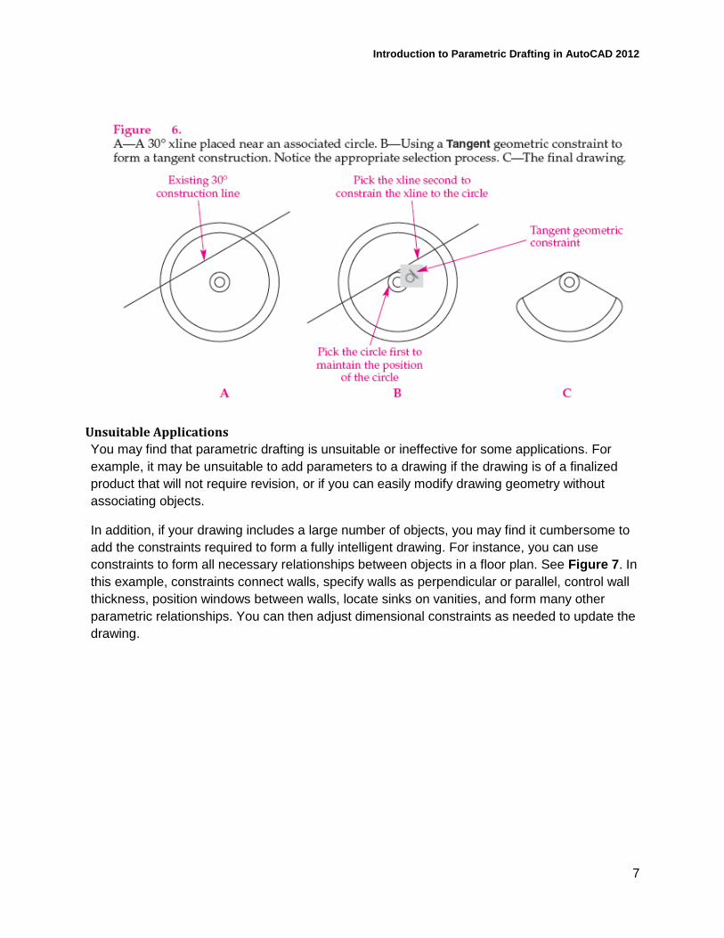
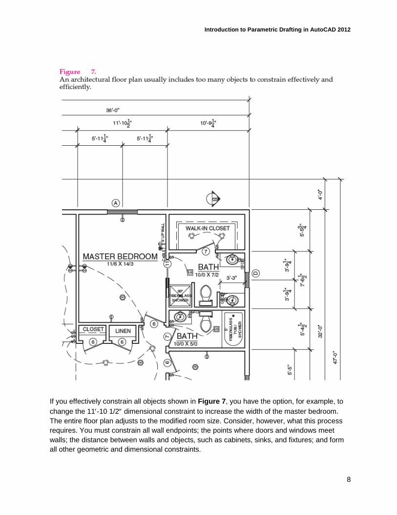
In addition, if your drawing includes a large number of objects, you may find it cumbersome to
add the constraints required to form a fully intelligent drawing. For instance, you can use
constraints to form all necessary relationships between objects in a floor plan. See Figure 7. In
this example, constraints connect walls, specify walls as perpendicular or parallel, control wall
thickness, position windows between walls, locate sinks on vanities, and form many other
parametric relationships. You can then adjust dimensional constraints as needed to update the
drawing.
Introduction to Parametric Drafting in AutoCAD 2012
8
If you effectively constrain all objects shown in Figure 7, you have the option, for example, to
change the 11-10 1/2 dimensional constraint to increase the width of the master bedroom.
The entire floor plan adjusts to the modified room size. Consider, however, what this process
requires. You must constrain all wall endpoints; the points where doors and windows meet
walls; the distance between walls and objects, such as cabinets, sinks, and fixtures; and form
all other geometric and dimensional constraints.
Introduction to Parametric Drafting in AutoCAD 2012
9
PROFESSIONAL BEST PRACTICE TIP
Constraints can also be used in multiview layout, to help maintain alignment between views.
GEOMETRIC CONSTRAINTS Geometric constraint tools allow you to add the geometric relationships required to build a
parametric drawing. You typically add geometric constraints, or at least a portion of the
necessary geometric constraints, before dimensional constraints to help preserve design intent.
You can infer certain geometric constraints while drawing and editing, or manually apply
geometric constraints to existing unconstrained geometry.
Inferring constraints is the fastest way to add geometric relationships. However, often a
combination of inferred and manually added geometric constraints is necessary. By default, a
constraint-specific icon is visible when you infer constraints to indicate the presence of a
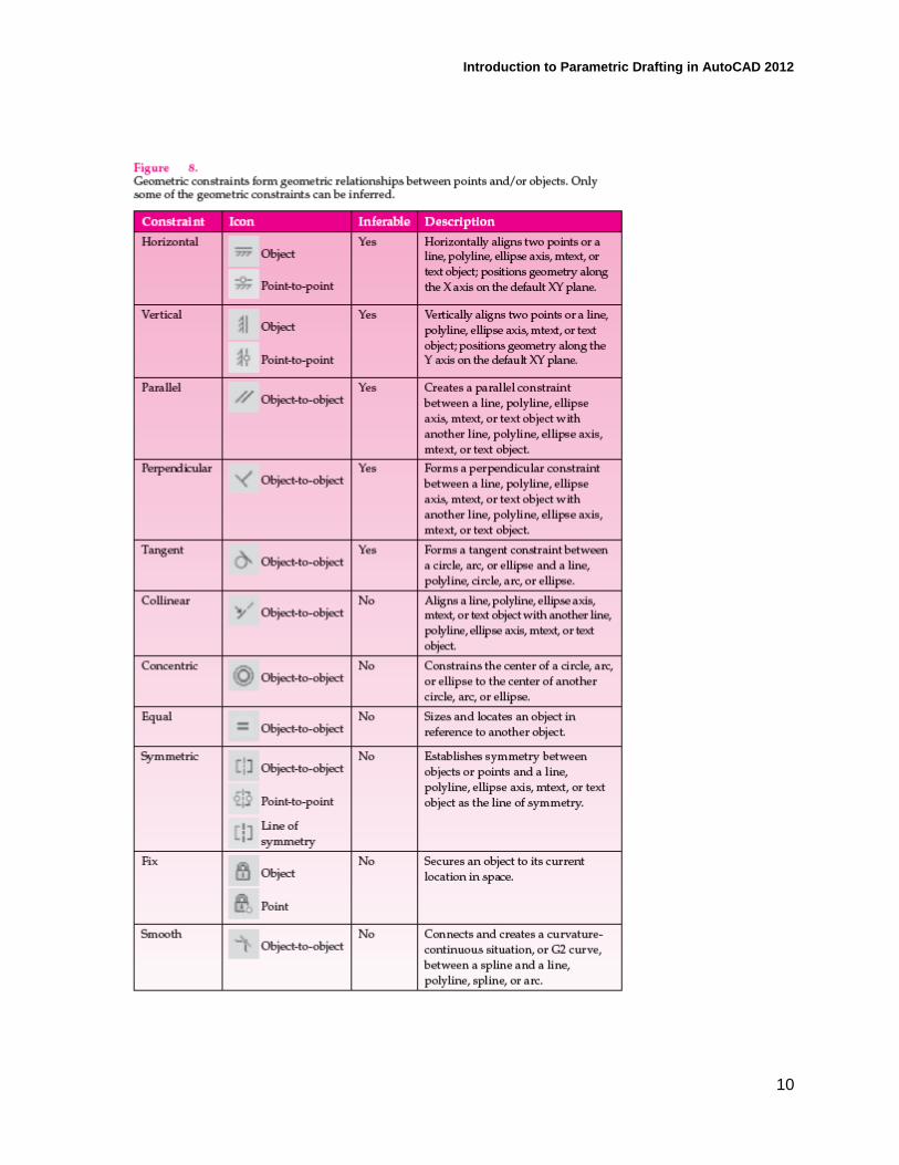
geometric constraint. View, adjust, and remove geometric constraints as needed. Figure 8
describes each geometric constraint.
Introduction to Parametric Drafting in AutoCAD 2012
10
Introduction to Parametric Drafting in AutoCAD 2012
11
PROFESSIONAL BEST PRACTICE TIP
Placing too many geometric constraints can cause problems as you progress through the
design process. Apply only the geometric constraints necessary to generate the required
geometric constructions.
Inferring Geometric Constraints
The CONSTRAINTINFER system variable controls whether AutoCAD infers constraints as you
create new geometry. The Infer Constraints button on the status bar provides a quick way to
toggle Infer Constraints on and off. When Infer Constraints is on, constraints are inferred
when you draw a new object. Appropriate object snaps, other drawing aids, and Infer
Constraints must be active in order to infer constraints, except when you use the
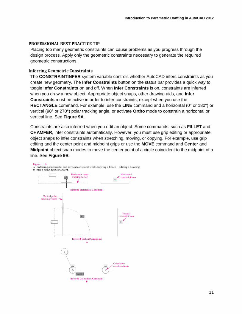
RECTANGLE command. For example, use the LINE command and a horizontal (0° or 180°) or
vertical (90° or 270°) polar tracking angle, or activate Ortho mode to constrain a horizontal or
vertical line. See Figure 9A.
Constraints are also inferred when you edit an object. Some commands, such as FILLET and
CHAMFER, infer constraints automatically. However, you must use grip editing or appropriate
object snaps to infer constraints when stretching, moving, or copying. For example, use grip
editing and the center point and midpoint grips or use the MOVE command and Center and
Midpoint object snap modes to move the center point of a circle coincident to the midpoint of a
line. See Figure 9B.
Introduction to Parametric Drafting in AutoCAD 2012
12
NOTE
The Quadrant, Intersection, Extension, and Apparent extension object snaps do not infer
constraints. The OFFSET, BREAK, TRIM, EXTEND, SCALE, MIRROR, ARRAY, and
MATCHPROP commands do not infer constraints. Exploding a polyline removes all inferred
constraints.
CAUTION
The Infer Constraints function can save drafting time by placing geometric constraints while
you draw or edit. However, use caution to ensure that appropriate geometric constructions
occur. You may have to replace certain constraints manually.
Manual Geometric Constraints
Infer constraints when possible and appropriate. You can also add geometric constraints
manually to apply geometric constraints that are not inferred automatically, as indicated in
Figure 8, to include additional geometric constraints as needed, or to constrain a
nonparametric drawing. The quickest way to place geometric constraints manually is to pick the
appropriate button from the Geometric panel of the Parametric ribbon tab. You can also type
GC followed by the name of the constraint, such as GCTANGENT, or select an option from the
GEOMCONSTRAINT command. Follow the prompts to make the required selection(s), form
the constraint, and exit the command.
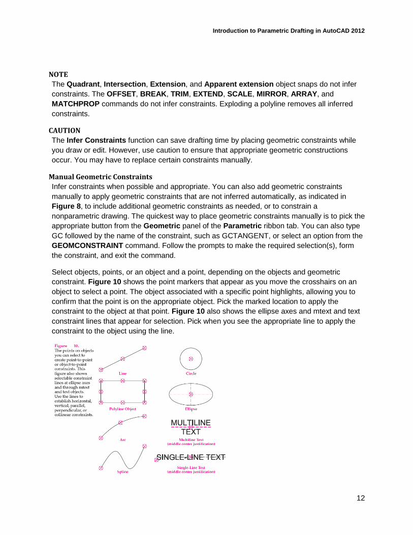
Select objects, points, or an object and a point, depending on the objects and geometric
constraint. Figure 10 shows the point markers that appear as you move the crosshairs on an
object to select a point. The object associated with a specific point highlights, allowing you to
confirm that the point is on the appropriate object. Pick the marked location to apply the
constraint to the object at that point. Figure 10 also shows the ellipse axes and mtext and text
constraint lines that appear for selection. Pick when you see the appropriate line to apply the
constraint to the object using the line.
Introduction to Parametric Drafting in AutoCAD 2012
13
The Fix constraint requires a single object or point selection. All other geometric constraints
require you to select two objects or points, or an object and a point. Generally, the first object
or point you select remains the same. The second object or point you select changes in relation
to the first selection, unless the second selection is fixed. For example, to create perpendicular
lines using the Perpendicular constraint, first select the line that will remain in the same
position at the same angle. Then select the line to make perpendicular to the first line,
assuming the second line is not fixed.
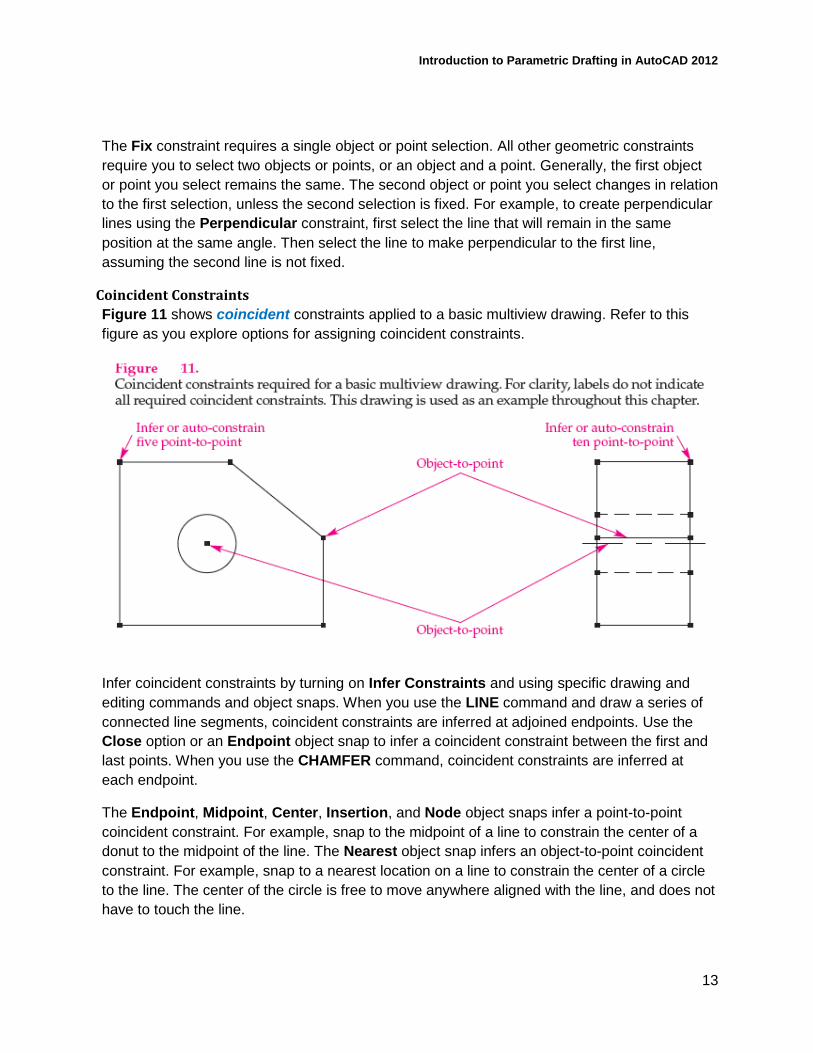
Coincident Constraints
Figure 11 shows coincident constraints applied to a basic multiview drawing. Refer to this
figure as you explore options for assigning coincident constraints.
Infer coincident constraints by turning on Infer Constraints and using specific drawing and
editing commands and object snaps. When you use the LINE command and draw a series of
connected line segments, coincident constraints are inferred at adjoined endpoints. Use the
Close option or an Endpoint object snap to infer a coincident constraint between the first and
last points. When you use the CHAMFER command, coincident constraints are inferred at
each endpoint.
The Endpoint, Midpoint, Center, Insertion, and Node object snaps infer a point-to-point
coincident constraint. For example, snap to the midpoint of a line to constrain the center of a
donut to the midpoint of the line. The Nearest object snap infers an object-to-point coincident
constraint. For example, snap to a nearest location on a line to constrain the center of a circle
to the line. The center of the circle is free to move anywhere aligned with the line, and does not
have to touch the line.
Introduction to Parametric Drafting in AutoCAD 2012
14
Use the GCCOINCIDENT or GEOMCONSTRAINT command to create a coincident constraint
manually. Move the pick box near a point on an existing object to display a point marker. Pick
the marked location, and then pick a point on another object to make the two points coincide.
Use the Object function to select an object and a point, as required to constrain a point along a
curve. The point does not have to contact the curve, and you can select the object first or
second. The Autoconstrain function allows you to select multiple objects to form coincident
constraints at every possible coincident intersection in a single operation. Right-click or press
[Enter] or the space bar to use the Autoconstrain function.
NOTE
Connected polyline segments act as if they are constrained, but they do not use or accept
coincident constraints at adjoined endpoints.
PROFESSIONAL BEST PRACTICE TIP
When you select points, be sure to select the points corresponding to the surface to be
constrained.
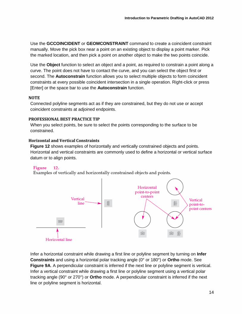
Horizontal and Vertical Constraints
Figure 12 shows examples of horizontally and vertically constrained objects and points.
Horizontal and vertical constraints are commonly used to define a horizontal or vertical surface
datum or to align points.
Infer a horizontal constraint while drawing a first line or polyline segment by turning on Infer
Constraints and using a horizontal polar tracking angle (0° or 180°) or Ortho mode. See
Figure 9A. A perpendicular constraint is inferred if the next line or polyline segment is vertical.
Infer a vertical constraint while drawing a first line or polyline segment using a vertical polar
tracking angle (90° or 270°) or Ortho mode. A perpendicular constraint is inferred if the next
line or polyline segment is horizontal.
Introduction to Parametric Drafting in AutoCAD 2012
15
Use the GCHORIZONTAL, GCVERTICAL, or GEOMCONSTRAINT command to create a
horizontal or vertical constraint manually. Select a line, polyline, ellipse axis, mtext, or text
object to constrain, or use the 2Points function to pick two points to align horizontally or
vertically.
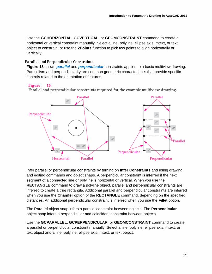
Parallel and Perpendicular Constraints
Figure 13 shows parallel and perpendicular constraints applied to a basic multiview drawing.
Parallelism and perpendicularity are common geometric characteristics that provide specific
controls related to the orientation of features.
Infer parallel or perpendicular constraints by turning on Infer Constraints and using drawing
and editing commands and object snaps. A perpendicular constraint is inferred if the next
segment of a connected line or polyline is horizontal or vertical. When you use the
RECTANGLE command to draw a polyline object, parallel and perpendicular constraints are
inferred to create a true rectangle. Additional parallel and perpendicular constraints are inferred
when you use the Chamfer option of the RECTANGLE command, depending on the specified
distances. An additional perpendicular constraint is inferred when you use the Fillet option.
The Parallel object snap infers a parallel constraint between objects. The Perpendicular
object snap infers a perpendicular and coincident constraint between objects.
Use the GCPARALLEL, GCPERPENDICULAR, or GEOMCONSTRAINT command to create
a parallel or perpendicular constraint manually. Select a line, polyline, ellipse axis, mtext, or
text object and a line, polyline, ellipse axis, mtext, or text object.
Introduction to Parametric Drafting in AutoCAD 2012
16
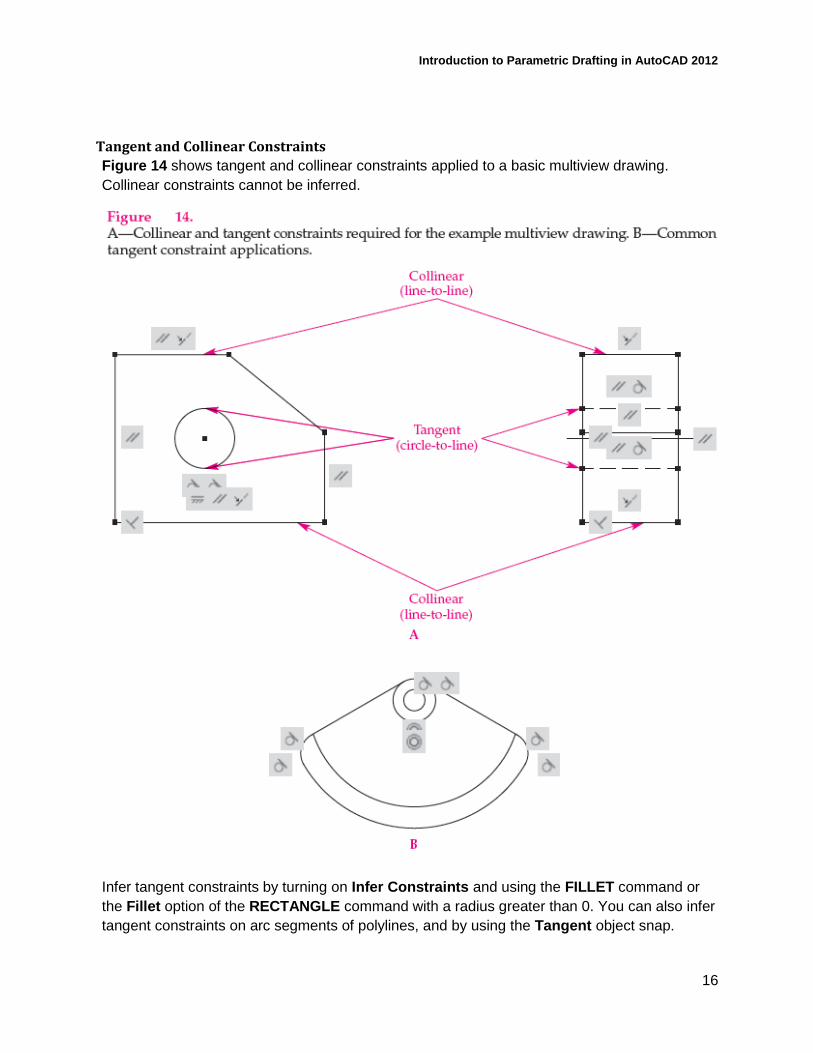
Tangent and Collinear Constraints
Figure 14 shows tangent and collinear constraints applied to a basic multiview drawing.
Collinear constraints cannot be inferred.
Infer tangent constraints by turning on Infer Constraints and using the FILLET command or
the Fillet option of the RECTANGLE command with a radius greater than 0. You can also infer
tangent constraints on arc segments of polylines, and by using the Tangent object snap.
Introduction to Parametric Drafting in AutoCAD 2012
17
NOTE
The Continue option of the ARC command does not infer a coincident or tangent constraint
between the existing object and the new arc.
Use the GCTANGENT or GEOMCONSTRAINT command to create a tangent constraint
manually. Select a circle, arc, or ellipse and then a line, polyline, circle, arc, or ellipse. Use the
GCCOLLINEAR or GEOMCONSTRAINT command to create a collinear constraint manually.
A collinear constraint is commonly used for applications such as aligning multiview surfaces.
Select a line, polyline, ellipse axis, mtext, or text object and then another line, polyline, ellipse
axis, mtext, or text object. Activate the Multiple function to select multiple objects to align in a
single operation. Right-click or press [Enter] or the space bar to complete a multiple constrain
operation.
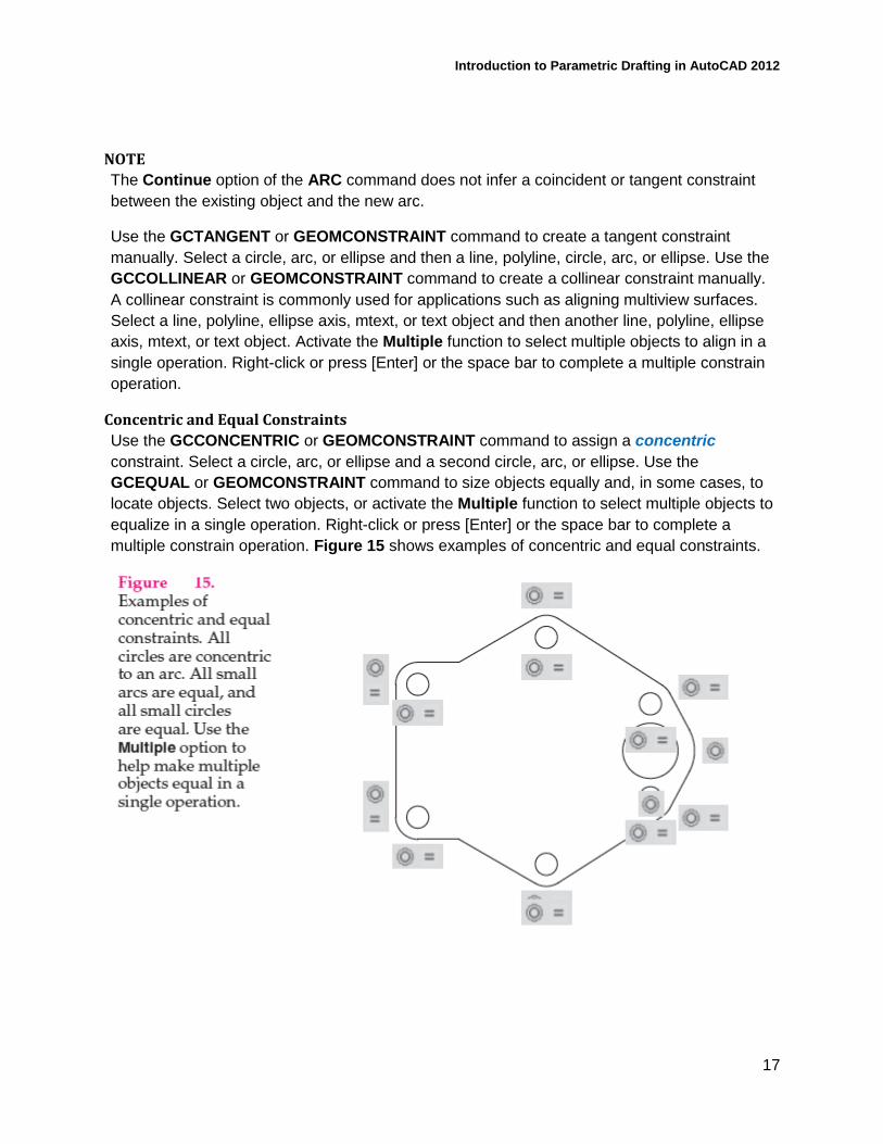
Concentric and Equal Constraints
Use the GCCONCENTRIC or GEOMCONSTRAINT command to assign a concentric
constraint. Select a circle, arc, or ellipse and a second circle, arc, or ellipse. Use the
GCEQUAL or GEOMCONSTRAINT command to size objects equally and, in some cases, to
locate objects. Select two objects, or activate the Multiple function to select multiple objects to
equalize in a single operation. Right-click or press [Enter] or the space bar to complete a
multiple constrain operation. Figure 15 shows examples of concentric and equal constraints.
Introduction to Parametric Drafting in AutoCAD 2012
18
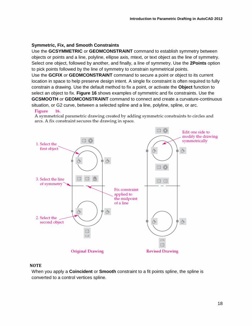
Symmetric, Fix, and Smooth Constraints
Use the GCSYMMETRIC or GEOMCONSTRAINT command to establish symmetry between
objects or points and a line, polyline, ellipse axis, mtext, or text object as the line of symmetry.
Select one object, followed by another, and finally, a line of symmetry. Use the 2Points option
to pick points followed by the line of symmetry to constrain symmetrical points.
Use the GCFIX or GEOMCONSTRAINT command to secure a point or object to its current
location in space to help preserve design intent. A single fix constraint is often required to fully
constrain a drawing. Use the default method to fix a point, or activate the Object function to
select an object to fix. Figure 16 shows examples of symmetric and fix constraints. Use the
GCSMOOTH or GEOMCONSTRAINT command to connect and create a curvature-continuous
situation, or G2 curve, between a selected spline and a line, polyline, spline, or arc.
NOTE
When you apply a Coincident or Smooth constraint to a fit points spline, the spline is
converted to a control vertices spline.
Introduction to Parametric Drafting in AutoCAD 2012
19
Using the AUTOCONSTRAIN Command
You can use the AUTOCONSTRAIN command in an attempt to add all required geometric
constraints in a single operation. Before using the AUTOCONSTRAIN command, access the
AutoConstrain tab of the Constraint Settings dialog box to specify the geometric constraints
to apply. The constraint priority determines which constraints are applied first. The higher the
priority, the more likely and often the constraint will form if appropriate geometry is available.
Select a constraint and use the Move Up and Move Down buttons to change its priority. Use
the corresponding Apply check marks and the Select All and Clear All buttons to omit specific
constraints during the constraining procedure.
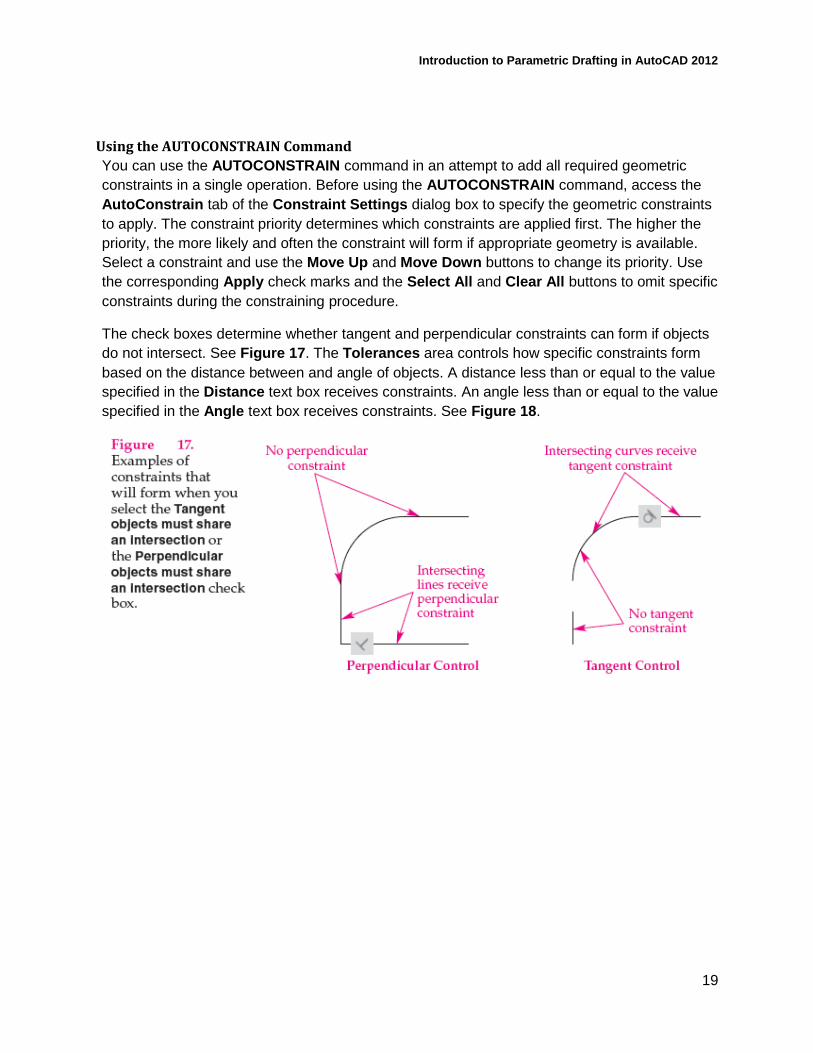
The check boxes determine whether tangent and perpendicular constraints can form if objects
do not intersect. See Figure 17. The Tolerances area controls how specific constraints form
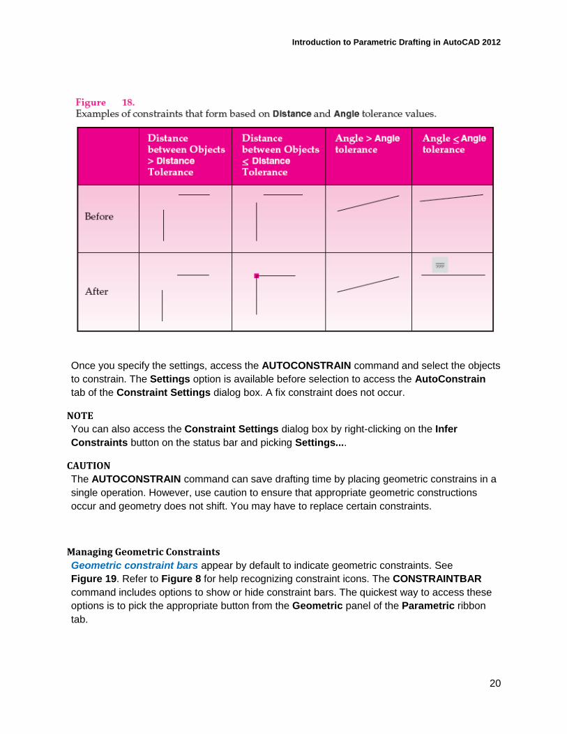
based on the distance between and angle of objects. A distance less than or equal to the value
specified in the Distance text box receives constraints. An angle less than or equal to the value
specified in the Angle text box receives constraints. See Figure 18.
Introduction to Parametric Drafting in AutoCAD 2012
20
Once you specify the settings, access the AUTOCONSTRAIN command and select the objects
to constrain. The Settings option is available before selection to access the AutoConstrain
tab of the Constraint Settings dialog box. A fix constraint does not occur.
NOTE
You can also access the Constraint Settings dialog box by right-clicking on the Infer
Constraints button on the status bar and picking Settings....
CAUTION
The AUTOCONSTRAIN command can save drafting time by placing geometric constrains in a
single operation. However, use caution to ensure that appropriate geometric constructions
occur and geometry does not shift. You may have to replace certain constraints.
Managing Geometric Constraints
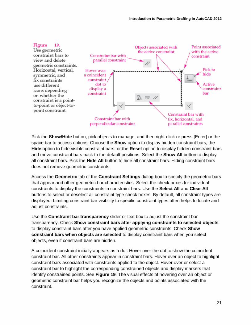
Geometric constraint bars appear by default to indicate geometric constraints. See
Figure 19. Refer to Figure 8 for help recognizing constraint icons. The CONSTRAINTBAR
command includes options to show or hide constraint bars. The quickest way to access these
options is to pick the appropriate button from the Geometric panel of the Parametric ribbon
tab.
Introduction to Parametric Drafting in AutoCAD 2012
21
Pick the Show/Hide button, pick objects to manage, and then right-click or press [Enter] or the
space bar to access options. Choose the Show option to display hidden constraint bars, the
Hide option to hide visible constraint bars, or the Reset option to display hidden constraint bars
and move constraint bars back to the default positions. Select the Show All button to display
all constraint bars. Pick the Hide All button to hide all constraint bars. Hiding constraint bars
does not remove geometric constraints.
Access the Geometric tab of the Constraint Settings dialog box to specify the geometric bars
that appear and other geometric bar characteristics. Select the check boxes for individual
constraints to display the constraints in constraint bars. Use the Select All and Clear All
buttons to select or deselect all constraint type check boxes. By default, all constraint types are
displayed. Limiting constraint bar visibility to specific constraint types often helps to locate and
adjust constraints.
Use the Constraint bar transparency slider or text box to adjust the constraint bar
transparency. Check Show constraint bars after applying constraints to selected objects
to display constraint bars after you have applied geometric constraints. Check Show
constraint bars when objects are selected to display constraint bars when you select
objects, even if constraint bars are hidden.
A coincident constraint initially appears as a dot. Hover over the dot to show the coincident
constraint bar. All other constraints appear in constraint bars. Hover over an object to highlight
constraint bars associated with constraints applied to the object. Hover over or select a
constraint bar to highlight the corresponding constrained objects and display markers that
identify constrained points. See Figure 19. The visual effects of hovering over an object or
geometric constraint bar helps you recognize the objects and points associated with the
constraint.
Introduction to Parametric Drafting in AutoCAD 2012
22
If a constraint bar blocks your view, drag it to a new location. To hide a specific constraint bar,
pick the Hide Constraint Bar button, or right-click and choose Hide. The right-click shortcut
menu also includes options for hiding all constraint bars and for accessing the Geometric tab
of the Constraint Settings dialog box.
Design changes sometimes require deleting existing constraints. To delete geometric
constraints, hover over an icon in the constraint bar and press [Delete], or right-click and select
Delete.
NOTE
You can also right-click with no objects selected to access a Parametric cascading menu that
provides options for displaying and hiding constraints and for accessing the Constraint
Settings dialog box.
PROFESSIONAL BEST PRACTICE TIP
To confirm that constraints, especially geometric constraints, are present and appropriate,
select an object to display grips and attempt to stretch a grip. As an object becomes
constrained, you should observe less freedom of movement. Stretching or attempting to stretch
grips is one of the fastest ways to assess design options and to analyze where a constraint is
still required. You know the drawing is constrained when you are no longer able to stretch the
geometry.
DIMENSIONAL CONSTRAINTS Dimensional constraints establish size and location parameters. You must include dimensional
constraints to create a truly parametric drawing. Dimensional constraints use a dynamic
format by default, and their appearance is different from traditional associative dimensions.
The easiest way to preset dimensional constraints to use the dynamic format is to pick the
Dynamic Constraint Mode button from the expanded Dimensional panel of the Parametric
ribbon tab.
You cannot modify how dynamic dimensional constraints appear, but you can change them to
an annotational format. To preset new dimensional constraints to use an annotational format,
pick the Annotational Constraint Mode button from the expanded Dimensional panel of the
Parametric ribbon tab. The annotational format uses the current dimension style. This class
focuses on using the Dynamic Constraint Mode function and then assigning annotational
format later. View, adjust, and remove dimensional constraints as needed.
Adding Dimensional Constraints
The quickest way to create dimensional constraints is to pick the appropriate button on the
Dimensional panel of the Parametric ribbon tab. You can also type DC followed by the name
of the constraint, such as DCLINEAR, or select an option from the DIMCONSTRAINT
command. To create a dimensional constraint, follow the prompts to make the required
Introduction to Parametric Drafting in AutoCAD 2012
23
selections, pick a location for the dimension line, enter a value to form the constraint, and exit
the command.
The process of selecting points or objects to locate dimensional constraint extension lines is
the same as that for adding geometric constraints. When a dimensional constraint command
requires you to pick two points or objects, the first point or object you select generally remains
the same. In some cases, you can consider the first point or object the datum. The second
point or object you select changes in relation to the first selection, unless the second selection
is fixed. When selecting points, be sure to select the points corresponding to the surface to
constrain.
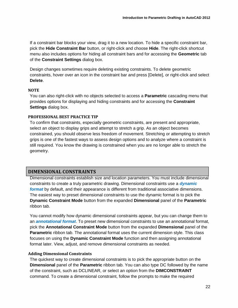
A text editor appears after you select the location for the dimension line, allowing you to specify
the dimension value. See Figure 20A. Each dimensional constraint is a parameter with a
specific name, expression, and value. By default, linear dimensions receive d names, angular
dimensions receive ang names, diameter dimensions receive dia names, and radial
dimensions receive rad names. Every parameter must have a unique name. The name of the
first of each type of dimension includes a 1, such as d1. The next dimension includes a 2, such
as d2, and so on. Use the text editor to enter a more descriptive name, such as Length, Width,
or Diameter. Follow the name with the = symbol and then the dimension value. Changing the
current dimension value modifies object size or location. Press [Enter] or pick outside of the
text editor to form the constraint. See Figure 20B.
The most basic way to specify the value of a dimensional constraint is to type a value in the
text editor. Dimensional constraint units reflect the current work environment and unit settings,
including length, angle type, and precision. Accept the current value if the drawing is accurate.
Enter a different value if the drawing is inaccurate, or to change object size.
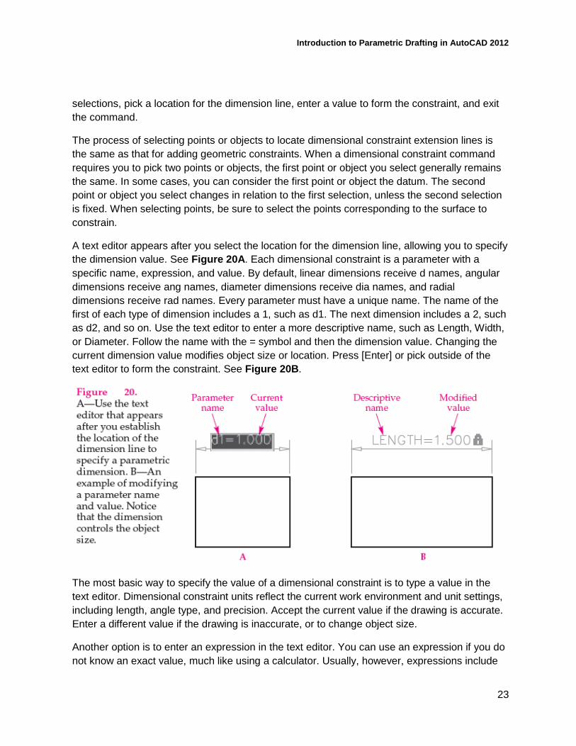
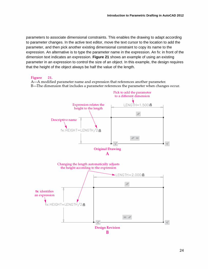
Another option is to enter an expression in the text editor. You can use an expression if you do
not know an exact value, much like using a calculator. Usually, however, expressions include
Introduction to Parametric Drafting in AutoCAD 2012
24
parameters to associate dimensional constraints. This enables the drawing to adapt according
to parameter changes. In the active text editor, move the text cursor to the location to add the
parameter, and then pick another existing dimensional constraint to copy its name to the
expression. An alternative is to type the parameter name in the expression. An fx: in front of the
dimension text indicates an expression. Figure 21 shows an example of using an existing
parameter in an expression to control the size of an object. In this example, the design requires
that the height of the object always be half the value of the length.
Introduction to Parametric Drafting in AutoCAD 2012
25
NOTE
If you add an existing parameter to the text of a different dimensional constraint, without
making a calculation, such as d1 = d2, the dimensional constraint uses the same value as the
reference parameter. This is necessary for many applications, but use an equal geometric
constraint when possible.
Linear Dimensional Constraints
Use the DCLINEAR or DIMCONSTRAINT command to place a horizontal or vertical linear
dimensional constraint. The Horizontal option sets the command to constrain only a horizontal
distance. The Vertical option sets the command to constrain only a vertical distance. The
Horizontal and Vertical options are helpful when it is difficult to produce the appropriate linear
dimensional constraint, such as when you are dimensioning the horizontal or vertical distance
of an angled surface.
Pick two points to specify the origin of the dimensional constraint, or use the Object function to
select a line, polyline, or arc to constrain. Move the dimension line to an appropriate location
and pick. Specify the dimension value and adjust the parameter name if desired. Press [Enter]
or pick outside of the text editor to form the constraint. Figure 20 and Figure 21 show
examples of linear dimensions.
Aligned Dimensional Constraints
Use the DCALIGNED or DIMCONSTRAINT command to place a linear dimensional constraint
with a dimension line that is aligned with an angled surface, with extension lines perpendicular
to the surface. Pick two points to specify the origin of the dimensional constraint, or use the
Object function to select a line, polyline, or arc to constrain.
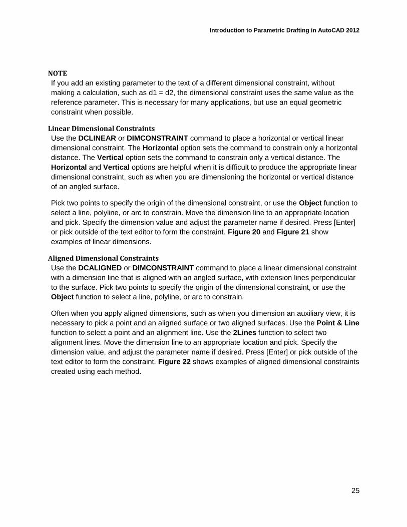
Often when you apply aligned dimensions, such as when you dimension an auxiliary view, it is
necessary to pick a point and an aligned surface or two aligned surfaces. Use the Point & Line
function to select a point and an alignment line. Use the 2Lines function to select two
alignment lines. Move the dimension line to an appropriate location and pick. Specify the
dimension value, and adjust the parameter name if desired. Press [Enter] or pick outside of the
text editor to form the constraint. Figure 22 shows examples of aligned dimensional constraints
created using each method.
Introduction to Parametric Drafting in AutoCAD 2012
26
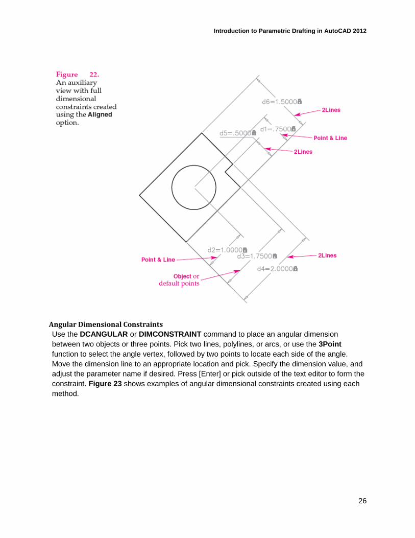
Angular Dimensional Constraints
Use the DCANGULAR or DIMCONSTRAINT command to place an angular dimension
between two objects or three points. Pick two lines, polylines, or arcs, or use the 3Point
function to select the angle vertex, followed by two points to locate each side of the angle.
Move the dimension line to an appropriate location and pick. Specify the dimension value, and
adjust the parameter name if desired. Press [Enter] or pick outside of the text editor to form the
constraint. Figure 23 shows examples of angular dimensional constraints created using each
method.
Introduction to Parametric Drafting in AutoCAD 2012
27
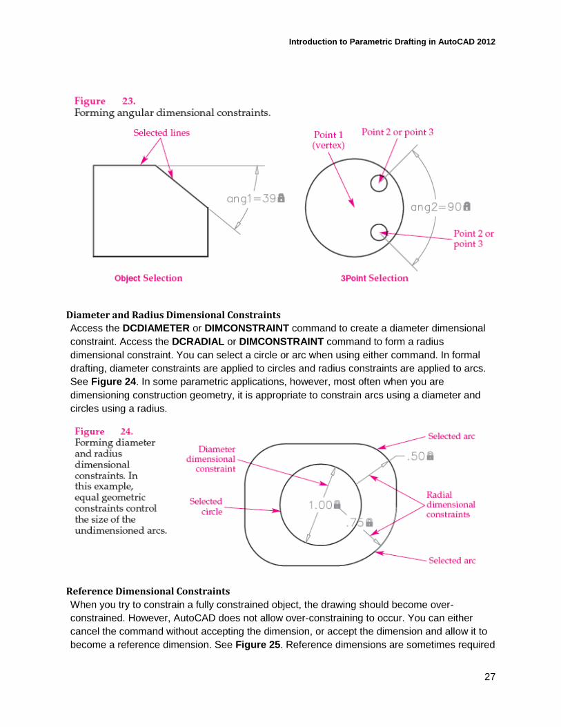
Diameter and Radius Dimensional Constraints
Access the DCDIAMETER or DIMCONSTRAINT command to create a diameter dimensional
constraint. Access the DCRADIAL or DIMCONSTRAINT command to form a radius
dimensional constraint. You can select a circle or arc when using either command. In formal
drafting, diameter constraints are applied to circles and radius constraints are applied to arcs.
See Figure 24. In some parametric applications, however, most often when you are
dimensioning construction geometry, it is appropriate to constrain arcs using a diameter and
circles using a radius.
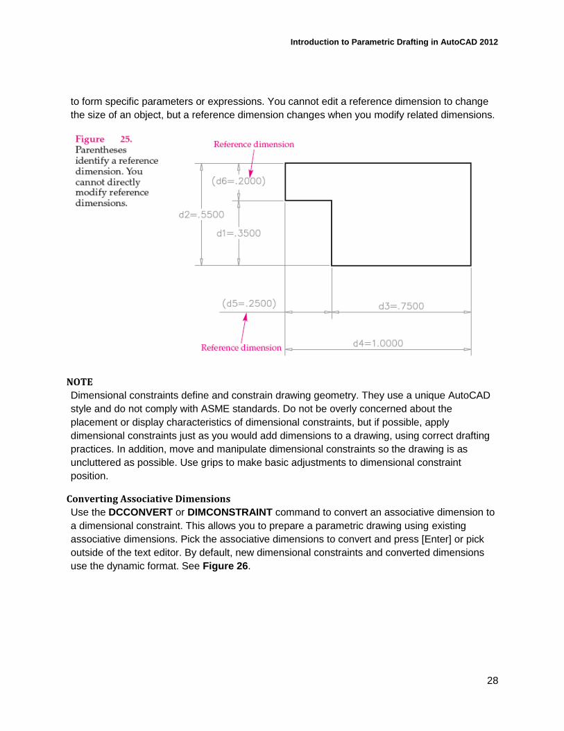
Reference Dimensional Constraints
When you try to constrain a fully constrained object, the drawing should become over-
constrained. However, AutoCAD does not allow over-constraining to occur. You can either
cancel the command without accepting the dimension, or accept the dimension and allow it to
become a reference dimension. See Figure 25. Reference dimensions are sometimes required
Introduction to Parametric Drafting in AutoCAD 2012
28
to form specific parameters or expressions. You cannot edit a reference dimension to change
the size of an object, but a reference dimension changes when you modify related dimensions.
NOTE
Dimensional constraints define and constrain drawing geometry. They use a unique AutoCAD
style and do not comply with ASME standards. Do not be overly concerned about the
placement or display characteristics of dimensional constraints, but if possible, apply
dimensional constraints just as you would add dimensions to a drawing, using correct drafting
practices. In addition, move and manipulate dimensional constraints so the drawing is as
uncluttered as possible. Use grips to make basic adjustments to dimensional constraint
position.
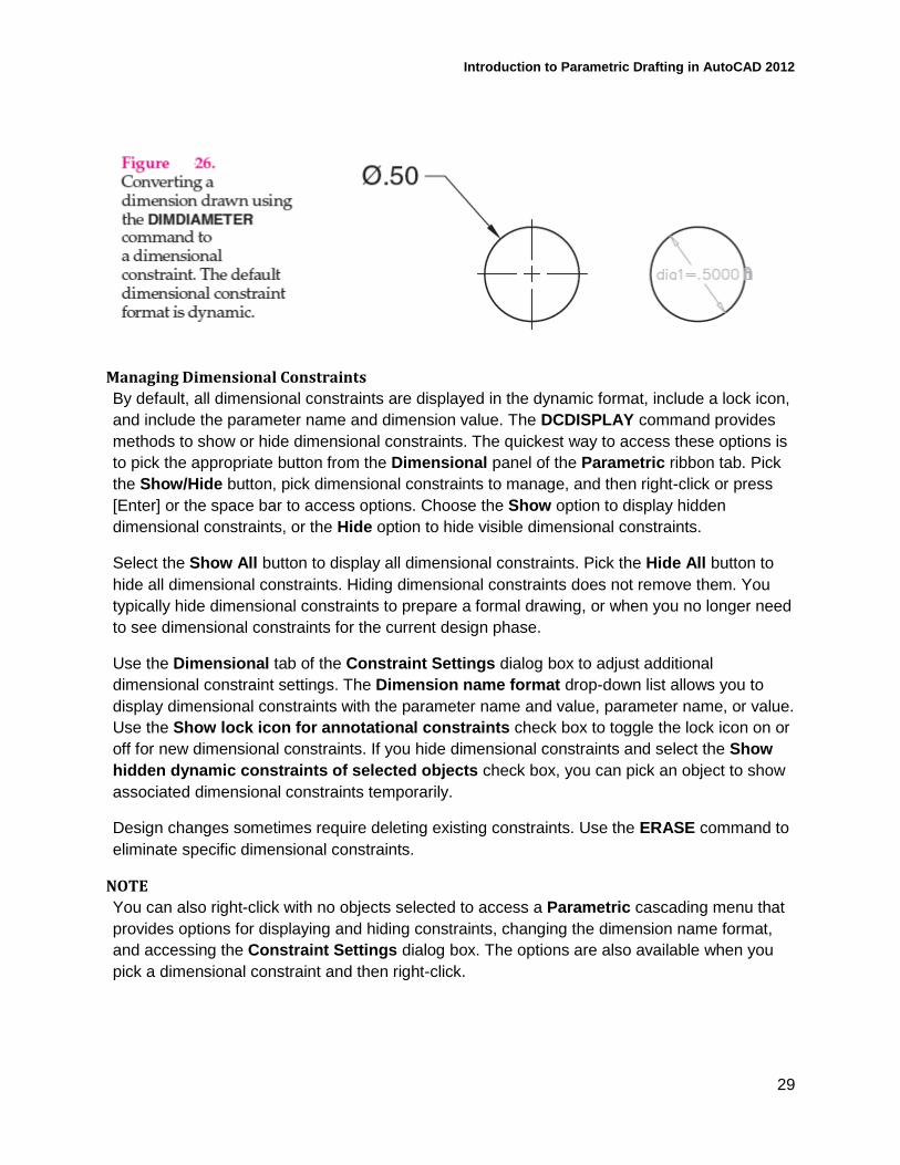
Converting Associative Dimensions
Use the DCCONVERT or DIMCONSTRAINT command to convert an associative dimension to
a dimensional constraint. This allows you to prepare a parametric drawing using existing
associative dimensions. Pick the associative dimensions to convert and press [Enter] or pick
outside of the text editor. By default, new dimensional constraints and converted dimensions
use the dynamic format. See Figure 26.
Introduction to Parametric Drafting in AutoCAD 2012
29
Managing Dimensional Constraints
By default, all dimensional constraints are displayed in the dynamic format, include a lock icon,
and include the parameter name and dimension value. The DCDISPLAY command provides
methods to show or hide dimensional constraints. The quickest way to access these options is
to pick the appropriate button from the Dimensional panel of the Parametric ribbon tab. Pick
the Show/Hide button, pick dimensional constraints to manage, and then right-click or press
[Enter] or the space bar to access options. Choose the Show option to display hidden
dimensional constraints, or the Hide option to hide visible dimensional constraints.
Select the Show All button to display all dimensional constraints. Pick the Hide All button to
hide all dimensional constraints. Hiding dimensional constraints does not remove them. You
typically hide dimensional constraints to prepare a formal drawing, or when you no longer need
to see dimensional constraints for the current design phase.
Use the Dimensional tab of the Constraint Settings dialog box to adjust additional
dimensional constraint settings. The Dimension name format drop-down list allows you to
display dimensional constraints with the parameter name and value, parameter name, or value.
Use the Show lock icon for annotational constraints check box to toggle the lock icon on or
off for new dimensional constraints. If you hide dimensional constraints and select the Show
hidden dynamic constraints of selected objects check box, you can pick an object to show
associated dimensional constraints temporarily.
Design changes sometimes require deleting existing constraints. Use the ERASE command to
eliminate specific dimensional constraints.
NOTE
You can also right-click with no objects selected to access a Parametric cascading menu that
provides options for displaying and hiding constraints, changing the dimension name format,
and accessing the Constraint Settings dialog box. The options are also available when you
pick a dimensional constraint and then right-click.
Introduction to Parametric Drafting in AutoCAD 2012
30
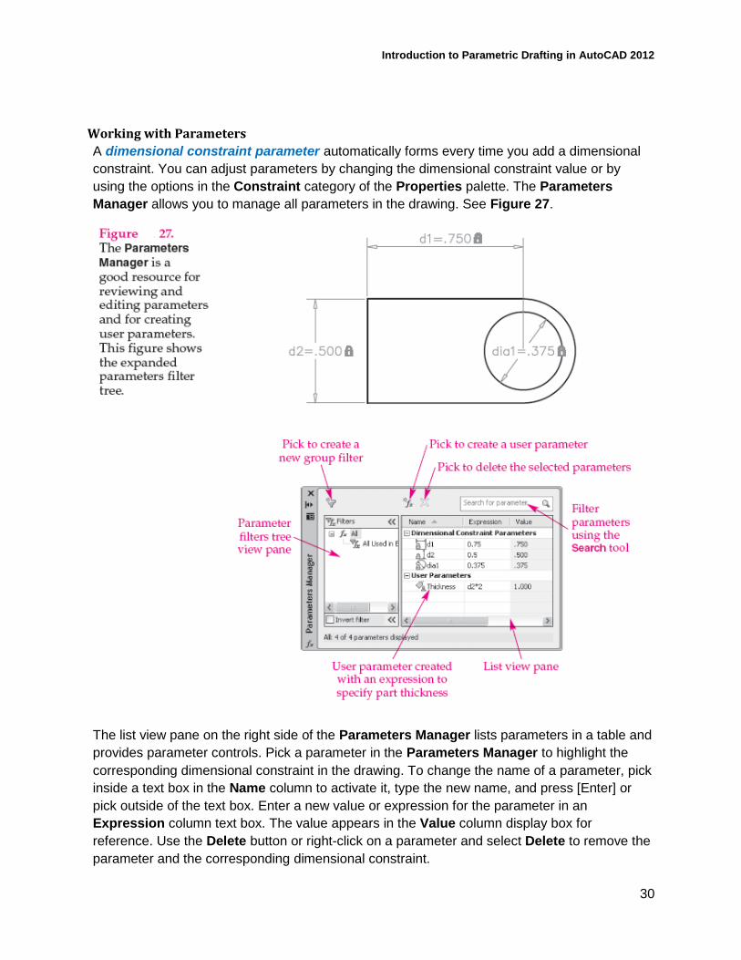
Working with Parameters
A dimensional constraint parameter automatically forms every time you add a dimensional
constraint. You can adjust parameters by changing the dimensional constraint value or by
using the options in the Constraint category of the Properties palette. The Parameters
Manager allows you to manage all parameters in the drawing. See Figure 27.
The list view pane on the right side of the Parameters Manager lists parameters in a table and
provides parameter controls. Pick a parameter in the Parameters Manager to highlight the
corresponding dimensional constraint in the drawing. To change the name of a parameter, pick
inside a text box in the Name column to activate it, type the new name, and press [Enter] or
pick outside of the text box. Enter a new value or expression for the parameter in an
Expression column text box. The value appears in the Value column display box for
reference. Use the Delete button or right-click on a parameter and select Delete to remove the
parameter and the corresponding dimensional constraint.
Introduction to Parametric Drafting in AutoCAD 2012
31
To specify user parameters, pick the User Parameters button to display a User Variables
node. User parameters function like dimensional constraints in the Parameters Manager.
Create user parameters in order to access specific parameters throughout the design process.
For example, if you know the thickness of a part will always be twice a certain dimensional
constraint, create a user parameter similar to the parameter shown in Figure 27 to define the
thickness. You can then use the custom parameter for reference and in expressions when you
place additional dimensional constraints.
Pick the Expand Parameters filter tree button or right-click in the list pane and select Show
Filter Tree to display the tree view pane on the left side of the Parameters Manager.
Parameter filters are typically appropriate when it becomes difficult to manage a very large
number of parameters. Filter a large list of parameters to make it easier to work with the
parameters needed for a specific drawing task.
Parameter filters are listed in alphabetical order in the All node. Select the All node to display
all parameters in the drawing. Pick the All Used in Expressions filter to display only
parameters used in or referenced by expressions. Pick the Invert filter check box to invert, or
reverse, a parameter filter. Select the Filter button or right-click on a filter name and select
New Group Filter to create a custom parameter group filter. A new group filter appears in the
filter tree view ready to accept a custom name, if desired. Select the All node at the top of the
filter tree area to display all the parameters in the drawing. Then, to add a parameter to the
group filter, drag a parameter from the list and drop it onto the group filter name. Right-click on
a filter name in the tree view or a parameter name in the list view to access options for
managing group filters.
NOTE
Use the Search text box to search for specific parameters according to parameter name.
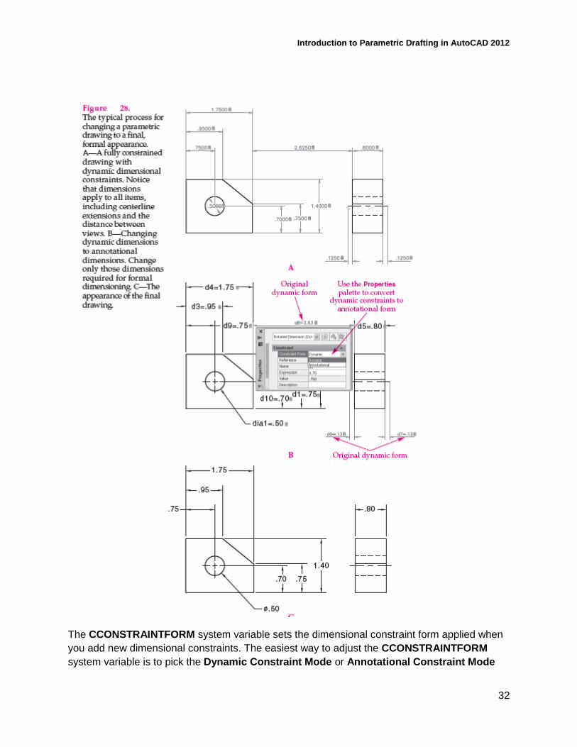
Dynamic and Annotational Form
This class focuses on using the default dynamic format for placing dimensional constraints.
Figure 28A shows the dimensional constraints required to fully constrain the example
multiview drawing in their dynamic format. The annotational format is more appropriate than
the dynamic format for formal dimensioning practices. Annotational constraints still control
object size and location.
Introduction to Parametric Drafting in AutoCAD 2012
32
The CCONSTRAINTFORM system variable sets the dimensional constraint form applied when
you add new dimensional constraints. The easiest way to adjust the CCONSTRAINTFORM
system variable is to pick the Dynamic Constraint Mode or Annotational Constraint Mode
Introduction to Parametric Drafting in AutoCAD 2012
33
button from the expanded Dimensional panel of the Parametric ribbon tab. You can also
preset the dimensional constraint format using the DIMCONSTRAINT command by selecting
the Form option, or by using the DCFORM command before creating a dimensional constraint.
NOTE
The specified Annotational or Dynamic form is a system variable and applies to new
dimensional constraints until you change it to the alternate setting.
Use the Constraint Form drop-down list in the Constraint category of the Properties palette
to change the dimensional constraint form assigned to existing dimensions. Figure 28B shows
the dimensional constraints in dynamic format that require changing to the annotational format
for the example multiview drawing. Annotational dimensions, especially those converted from
dynamic dimensions, often require that you make format and organizational changes to
prepare the final drawing. You may also have to add non-parametric dimensions. Make the
following changes to create the final drawing shown in Figure 28C.
• Hide all geometric constraints and dynamic dimensions.
• Disable the lock icon display.
• Change the dimension name format to Value.
• Make basic dimension style overrides and dimension location adjustments if necessary.
PARAMETRIC EDITING You can adjust existing parametric drawings in a variety of ways. Drawing additional
unconstrained objects adds geometry that requires constraining to make the drawing fully
parametric once again. You may need to delete or replace existing constraints to constrain new
objects. Erasing objects and exploding polylines removes constraints. If you erase geometry
associated with an expression, an alert appears asking if you want to convert the dimensional
constraint to a user parameter, maintain the information, or remove the parameter with the
dimensional constraint.
Modifying Dimensional Constraints
Adjust dimensional constraints to make design changes to a constrained drawing. To edit a
dimensional constraint value, double-click on the value, or select the dimensional constraint,
right-click, and pick Edit Constraint. The text editor appears, allowing you to make changes.
Press [Enter] or pick outside of the text editor to complete the operation.
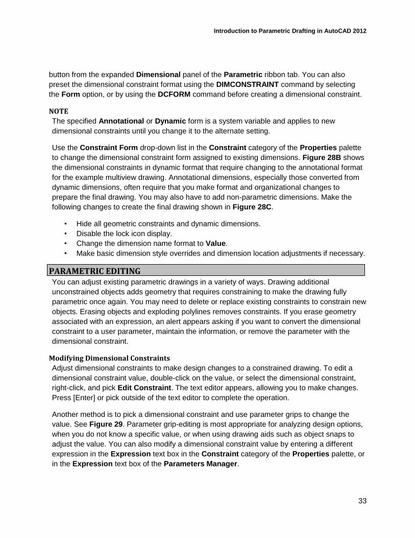
Another method is to pick a dimensional constraint and use parameter grips to change the
value. See Figure 29. Parameter grip-editing is most appropriate for analyzing design options,
when you do not know a specific value, or when using drawing aids such as object snaps to
adjust the value. You can also modify a dimensional constraint value by entering a different
expression in the Expression text box in the Constraint category of the Properties palette, or
in the Expression text box of the Parameters Manager.
Introduction to Parametric Drafting in AutoCAD 2012
34
NOTE
If a drawing includes enough geometric constraints, and the geometric constraints are
accurate, changing dimensions should maintain all geometric relationships.
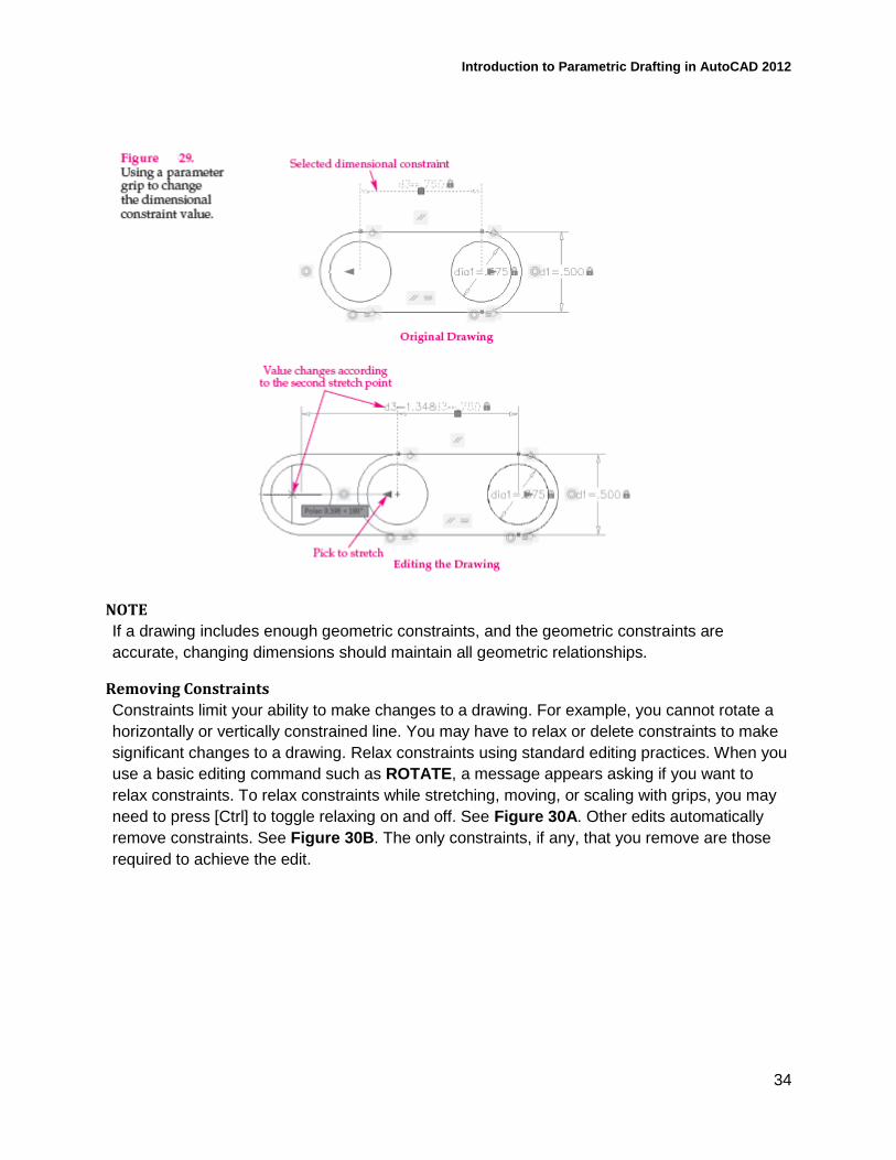
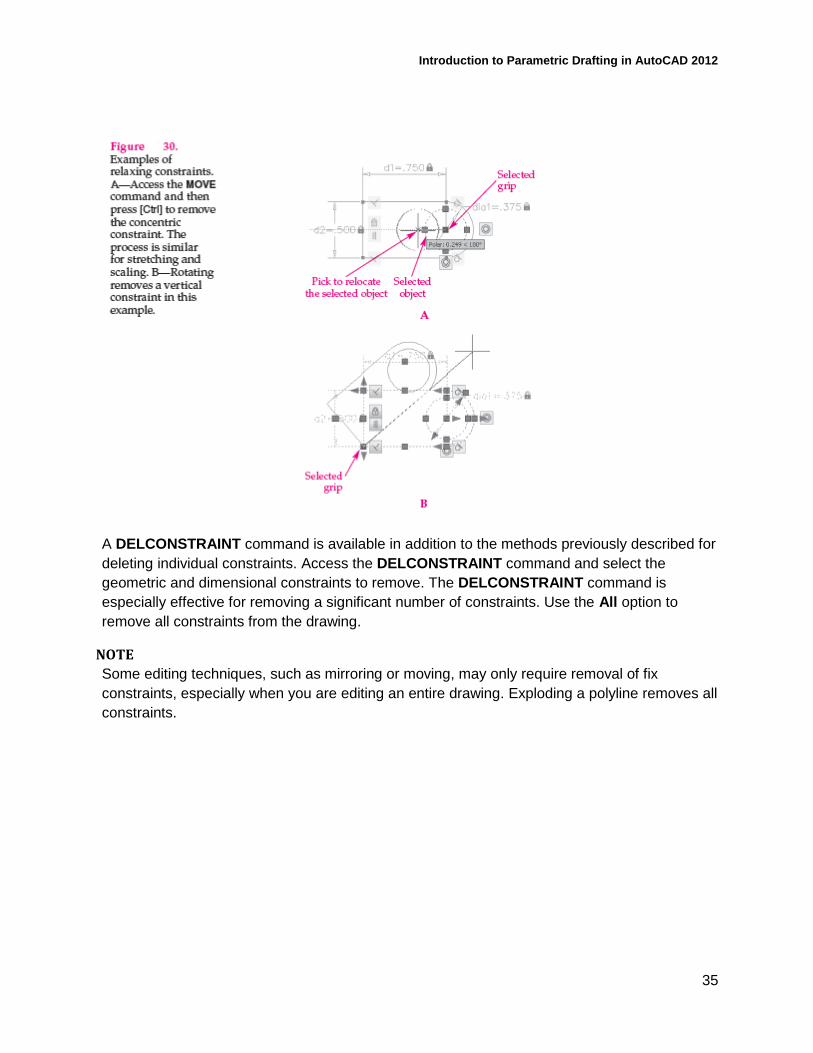
Removing Constraints
Constraints limit your ability to make changes to a drawing. For example, you cannot rotate a
horizontally or vertically constrained line. You may have to relax or delete constraints to make
significant changes to a drawing. Relax constraints using standard editing practices. When you
use a basic editing command such as ROTATE, a message appears asking if you want to
relax constraints. To relax constraints while stretching, moving, or scaling with grips, you may
need to press [Ctrl] to toggle relaxing on and off. See Figure 30A. Other edits automatically
remove constraints. See Figure 30B. The only constraints, if any, that you remove are those
required to achieve the edit.
Introduction to Parametric Drafting in AutoCAD 2012
35
A DELCONSTRAINT command is available in addition to the methods previously described for
deleting individual constraints. Access the DELCONSTRAINT command and select the
geometric and dimensional constraints to remove. The DELCONSTRAINT command is
especially effective for removing a significant number of constraints. Use the All option to
remove all constraints from the drawing.
NOTE
Some editing techniques, such as mirroring or moving, may only require removal of fix
constraints, especially when you are editing an entire drawing. Exploding a polyline removes all
constraints.
Introduction to Parametric Drafting in AutoCAD 2012
36
PROFESSIONAL BEST PRACTICE TIP
Occasionally, constraining geometry causes objects to twist out of shape, making it difficult to
control the size and position of the drawing. Use the UNDO command to return to the previous
design. Consider the following suggestions to help avoid this situation:
• Use standard and accurate drafting practices to construct objects at or close to
their finished size.
• Add as many geometric constraints as appropriate before dimensional
constraints.
• Dimensionally constrain the largest objects first.
• Move objects to a more appropriate location, if necessary, and change object
size before constraining.
Reference
Portions of this document are copyrighted by Goodheart-Willcox Company, Inc. and reproduced
with permission from the textbook AutoCAD and Its Applications – Basics 2012.