Embed Size (px)
Citation preview

1
Introduction to Optical Stochastic
Cooling and the Bates Linear Accelerator Center at MIT
Robert P. Redwine
Director, Bates Linear Accelerator Center
12/1/2009 Muon Collider Design Workshop, BNL

2
MIT Bates Linear Accelerator Center
12/1/2009 Muon Collider Design Workshop, BNL

3
History• 500 MeV linear electron accelerator with recirculator, polarized
electron source and storage ring
• Recirculator nearly doubles energy to 1 GeV
• Storage ring can stack pulses from the accelerator to at least 225 mA; beam stores for 25-30 minutes
• Beam polarization is kept longitudinal at target with a Siberian Snake
• Ran nuclear physics experiments for 31 years, under a cooperative agreement with US DOE
Siberian Snake
12/1/2009 Muon Collider Design Workshop, BNL

4
Present
• MIT now owns the site and facilities
• Bates is a multi-purpose laboratory
• 20+ physicists, engineers and technicians on-site
12/1/2009 Muon Collider Design Workshop, BNL

5
Optical Stochastic Cooling• Optical Stochastic Cooling (OSC) is potentially
important for several applications, including a muon collider.
• The MIT/Bates lab represents an almost ideal opportunity for a demonstration of OSC.
• NP and HEP at DOE are evaluating a proposal from Bates to test OSC.
• Dennis Kovar would like to hear directly from the muon collider community about the importance of pursuing OSC.
12/1/2009 Muon Collider Design Workshop, BNL

Optical Stochastic Cooling of a 100 GeV Muon Beam
(A. Zholents & M. Zolotorev)
Christoph TschalärBates Linear Accelerator Center
Massachusetts Institute of Technology
12/1/2009 6Muon Collider Design Workshop, BNL

Goal:
• Cool a beam of 109 muons at 100 GeV in ≤ 4ms (muon life-time = 2.2 ms)
Transverse:
Longitudinal:
Total 6-dimensional emittance reduction = 4·1010
7 102 10 2 10z m m
8 122 10 3 10x yx y m m
12/1/2009 7Muon Collider Design Workshop, BNL

OSC Cooling Section
Particle in first undulator emits coherent light pulse of length Nl
Light pulse delayed and amplified Particle receives
longitudinal kick from own amplified light pulse in 2nd undulator
N S N S N Charged particle beam delayed
by magnetic bypass
12/1/2009 8Muon Collider Design Workshop, BNL

OSC FormalismPhase shift Mean shift
Mean cooling per transition:
Ns = number of muons whose light signals overlap
51 52 xkR x kR kh 2 2 2 2 2 2 2 2 2 2 2 2
51 52 xk R x k R k h v w
2
2
2 2
2 2 251
/ / 4 ;
/ / / 2
L s
x x T s
Gkh e G N n
x x Gk R e G N n x
/ ; overlap distance 3s bunch bunchN N m
12/1/2009 9Muon Collider Design Workshop, BNL

Maximize αL,T
• Optimize G: incoherent heating = ½ coherent cooling
for
• Optimize phase shift
→
Dual challenge: make Ns very small, G very large
2 22 2
; L Ts s
w ve e
N n N n
2 2/2 /2
0
2 /
s s
w vxG G e e
N n N n
2 2 2 1v w
2 2
0
2; ; L T
s s s
w v wG
e N n e N n e N n
12/1/2009 10Muon Collider Design Workshop, BNL

• Stretch incoming beam bunch from 0.2m to 100m length
• Compress δav from 10-3 to 2·10-6 → reduces Ns to
→
87 10 3.7 /100 25; 75sm m N n 3 3
, ,10 ; 0.7 10L T x T y
C=1100m
Three
Conceptual Solution (Zholents & Zolotorev)
12/1/2009 11Muon Collider Design Workshop, BNL

Initial and Final Beam Parameters in the Cooling Ring
initial final change
2·10-4 2.5·10-6 1/80
1·10-4 1.2·10-6 1/80
2·10-6 2·10-9 1/1000
8·10-11 1.8·10-21 1/4·1010
, ( )
, ( )x y
x y m
rad
3, , ( )L T x T y m
12/1/2009 12Muon Collider Design Workshop, BNL

Initial and Final Lattice Parameters for Optimal Cooling at 0.8 μm Optical
Wavelength
initial finalchange
100 ~1000 ~10
4·10-4 3.3·10-2 83
-0.1 -30 300
-0.025 -25 1000
51
56
( )
( )
( )
m
R
R m
h m
12/1/2009 13Muon Collider Design Workshop, BNL

Technical ChallengesCooler Lattice
• Very large dispersion• Very large and rapid change of cooling section time-of-
flight parameters:
→ use 3 parallel cooler rings for initial, middle, and final cooling phase
→ reduce time-of-flight parameter changes to ~6 and dispersion change to ~2 in each ring
• Cool both x and y dimension of the beam→ attach bypass to cooler ring to rotate transverse beam
plane by 900 periodically
100 1000m
51 56 increases by 80, increases by 300 in 4 msR R
12/1/2009 14Muon Collider Design Workshop, BNL

Light Amplifier
• Optimized gain factor at the beginning of the cooling cycle, decreasing
exponentially to 2·10-11 at the end, requires an average amplifier output power of
for each of the 10 cooling sections.
→ Use fast Optical Parametric Amplifier (OPA) developed by MIT group (F. Kärtner). Expected power levels of 1 kW reachable with intensive development in 5-10 years
8
0
22 10
s
wG
e N n
200 Watt at 0.8 m optical wavelengthP
12/1/2009 15Muon Collider Design Workshop, BNL

Conclusion
• OSC for muon beams of 109 particles is conceptually feasible
• Requires development of cooler lattices with large dispersions and rapidly varying time-of-flight characteristics
• Requires development of kW-level OPA in the 1μm wavelength region
• Requires experimental test of OSC to prove feasibility and develop basic tools and diagnostics
12/1/2009 16Muon Collider Design Workshop, BNL

17
• Comparison of muon collider designs: “conventional” vs. “OSC”
• OSC experiment at Bates: motivation, plan
Optical Stochastic Cooling for a 2 TeVx2TeV Muon Collider &
OSC Experiment at the MIT-Bates South Hall Ring
F. Wang MIT-Bates Linear Accelerator Center
12/1/2009 Muon Collider Design Workshop, BNL
Units
1996 report(Table 13.5)
HEPAP P5R.B.Palmer, March,2008
OSC A.Zholents et al.PRST-AB 2001
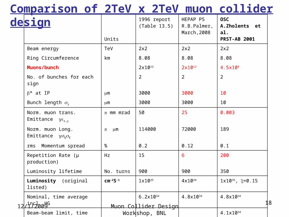
Beam energy TeV 2x2 2x2 2x2
Ring Circumference km 8.08 8.08 8.08
Muons/bunch 2x10¹² 2x10¹² 4.5x10⁸
No. of bunches for each sign 2 2 2
* at IP m 3000 3000 10
Bunch length z m 3000 3000 10
Norm. muon trans. Emittance x,y
mm mrad 50 25 0.003
Norm. muon Long. Emittance bE
m 114000 72000 189
rms Momentum spread % 0.2 0.12 0.1
Repetition Rate (μ production) Hz 15 6 200
Luminosity lifetime No. turns 900 900 350
Luminosity (original listed) cm-2S-1 1x1035 4x1034 1x1035, =0.15
Nominal, time average incl. HG 6.2x1034 4.8x1034 4.8x1034
Beam-beam limit, time average =0.12
4.1x1034
(6.4x1034, =0.15)
Comparison of 2TeV x 2TeV muon collider design
1812/1/2009 Muon Collider Design Workshop,
BNL

factor.reduction Hourglass1/75.0
TeV. 2at for ms 42 τfactor,Decay
rate. repetition:f
lifetime, Luminosity:t,factor time theis
,frequency) revolution signeach ofnumber bunch (frequency colliding:f4
*
2
rep
Llife
c
2
2
zhg
t
deacy
Lliferepf
hgdecayfbc
f
ef
tfT
ffTNf
L
Llife
Nominal time-averaged luminosity:
Luminosity at beam-beam limit:
parameter. beambeam: IP,at spreadangular rms beam:
4
'*
'*22
22
hgdecayf
c ffTr
fL
1912/1/2009 Muon Collider Design Workshop,
BNL

20
Neutrino Radiation ChallengesBruce J. King, BNL-67408, CAP-281-Muon-00C, April 2000.
12/1/2009 Muon Collider Design Workshop, BNL

3
232
4
182
[ ] 3.7 10
1.1 10
L:ν beam distance to surface. L 2Rd; R:earth radius; d: collider plane depth.
/
ave
ss
ss
ssstraight collider
N E TeVD Sv
L km
f N E TeVD Sv
L km
f L C
Neutrino-induced radiation dose B.J. King, PAC 318, 1999
“Equilibrium approximation” for worst-case radiation calculations.
21
Unit of dose equivalent: 1 Sievert [Sv] =1 J/kg= 100 remThe U.S. federal off site radiation limit: 1 mSv/year=100 mrem/year.1% Dfed : 1 mrem/year
12/1/2009 Muon Collider Design Workshop, BNL

Units
1996 report(Table 13.5)
HEPAP P5R.B.Palmer, March,2008
OSC A.Zholents et al.PRST-AB 2001
Beam energy TeV 2x2 2x2 2x2
Ring Circumference km 8.08 8.08 8.08
Muons/bunch 2x10¹² 2x10¹² 4.5x10⁸
No. of bunches for each sign 2 2 2
Neutrino induced radiation*
Collider reference depth m 135 135 135
Keeps off site dose mrem/year < 1
Dave: Ave. rad. In plane mrem 0.04 0.01 3.2x10⁻⁵
Ld= beam distance to surface km 42 42 42
Straight section length for 10xDave. Rad.
m 1.35 1.35 1.35
Dss:Dose from straight sections
mrem
Dss from 13.5m (~FODO ‘s) 3.6 1.1 1.6x10⁻³
Dss from 268m straights** 71 21 0.03
Comparison of 2TeV x 2TeV muon colliders (Continued)
22
*B. J. King, PAC 99, p.318.** No vertical wave field
12/1/2009 Muon Collider Design Workshop, BNL

Shielding the Muon Collider Interaction RegionC.J. Johnstone and N.V.Mokhov, PAC 97, p.414
2312/1/2009 Muon Collider Design Workshop,
BNL

OSC
C=8088mCd=1100m
2412/1/2009 Muon Collider Design Workshop,
BNL
OSC in Muon Collider scheme
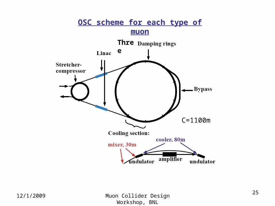
C=1100m
Three
OSC scheme for each type of muon
2512/1/2009 Muon Collider Design Workshop,
BNL

26
Summary of comparison
OSC feature: Cooling at ~100 GeV• Much smaller emittance:
each transverse plane: ~1/8000, longitudinal ~1/400 • ~4400 times fewer muons per beam, same luminosity
Advantages:• Dramatic reduction of off-site neutrino induced radiation
hazard• 50 times less proton beam pulse intensity• Background improvement in the detector
Disadvantages:• Increases the complexity of muon collider facility
12/1/2009 Muon Collider Design Workshop, BNL

12/1/2009 Muon Collider Design Workshop, BNL
27
OSC experiment at BatesFirst Experimental Demonstration of Optical Stochastic Cooling
with the MIT-Bates South Hall RingW. Barletta, P. Demos, K. Dow, J. Hays-Wehle, E. Ihloff, J. Kelsey, B. McAllister, R. Milner,
R. Redwine (P.I.), S. Steadman, C. Tschalär, E. Tsentalovich, and F. Wang
Bates R&E/Accelerator Center and
Laboratory for Nuclear Science, MIT
F. Kärtner, J. Moses, and A. Siddiqui
Research Laboratory of Electronics, MIT
M. Babzien, M. Bai, M. Blaskiewicz, M. Brennan, W. Fischer,
V. Litvinenko, T. Roser and V. Yakimenko
Brookhaven National Laboratory
S.Y. Lee
Indiana University Cyclotron Facility
W. Wan, A. Zholents and M. Zolotorev
Lawrence Berkeley National Laboratory

28
Bates experiment goals• Proof-of-principle • OSC concept study: cooling mechanism, OSC & ring lattice integration, fast
cooling test• Address key technical issues: optical amplifier, magnet bypass, diagnostics
& control
Motivation of experiment• OSC has never been demonstrated in practice.• The cost and time required for testing OSC in high-energy hadron machine
or muon collider will be significant.• Experiment with e-beams is quick and cost-effective.
12/1/2009 Muon Collider Design Workshop, BNL
Why with Bates South Hall Ring• Bates SHR ring energy range is appropriate, machine lattice is very flexible.• There is a long straight section available for OSC insertion. • Bates facility is available for dedicated OSC testing.
29
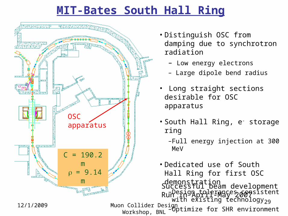
MIT-Bates South Hall Ring
• Distinguish OSC from damping due to synchrotron radiation
– Low energy electrons
– Large dipole bend radius
• Long straight sections desirable for OSC apparatus
• South Hall Ring, e- storage ring –Full energy injection at 300 MeV
• Dedicated use of South Hall Ring for first OSC demonstration–Design tolerances consistent with
existing technology
–Optimize for SHR environment
C = 190.2 m = 9.14 m
OSC apparatus
Successful beam developmentRun in April-May 2007
12/1/2009 Muon Collider Design Workshop, BNL

30
Bates Experiment Parameters
SHR Natural IBS effect
Beam energy (MeV) , RF: f(GHz)/ V (kV) 300, 2.856/14
Electrons/bunch, bunch number, average current 1108 , 12, 0.3mA
Chicane: L(m), bending angle (mrad)/ radius(m) 5.55, 65 / 3.85
Inverse chicane matrix elements: R51, R52, R56 8.610-4, 2.52mm, -12mm
Undulator: L, period, 2m, 20cm, 2m
Lattice parameters at second undulator =3m, =6m , =2
SR damping time x (sec.) 4.83
Beam emittance, x (nm), 10% coupling 47 96
Energy spread, rms bunch length 8.5e-5, 5.1 mm 1.67e-4, 9.8mm
0, 0
20 0
, 2
1 0
1 02
xIBS x x syn x OSC
x
OSCIBS l syn
g g f
fg g
Growth (damping) rates at equilibrium state:
12/1/2009 Muon Collider Design Workshop, BNL

31
SHR Lattice for OSC ExperimentOSC Insertion
12/1/2009 Muon Collider Design Workshop, BNL

32
Bates OSC apparatus: Optical amplifier and layout
50 ps, 1030 nm Laser20 MHz, 20 W, 1 mJ Undulator
Radiation
270cm 24cm
Beam radius:
103cm 103cm 270cm
f = 12 cm
Lenses and wedges, 1mm, n=1.5Total optical delay is only 5.5 mm ~ 20 ps
f = 380 cm
BaF2 wedges1mm
0.2 pJ 4 µW
2 nJ 40 mW
2 mmPPLNn=2
f = 380 cm
w = 0.5 mm
F. Kärtner, A. Siddiqui
PPLN: Periodically Poled Lithium Niobate
12/1/2009 Muon Collider Design Workshop, BNL

33
Bates OSC apparatus: Small-angle bypass
Based on Optical Parametric Amplifier: total signal delay ~20ps only! Then we can choose small-angle chicane with path length increase of 20 ps ~ 6 mm.
4 parallel-edge benders and one (split) weak field lens. Choose =65 mrad, L=6mm.
B1 B2 Q1 Q2 B3 B4OpticalAmplifier
0 1 2 m
Q
Tolerances to conserve coherence are much relaxed for small-angle bypass.
12/1/2009 Muon Collider Design Workshop, BNL

34
SHR OSC experiment numerical modeling:
x and optical amplification
Optimal cooling achieved by adjusting optical amplification.
12/1/2009 Muon Collider Design Workshop, BNL
Observation of beam transverse size changes during cooling process

35
OSC Tuning DiagnosticsJ. Hays-Wehle, W. Franklin
• Interference signal is maximal when light amplitudes same (low gain alignment).
• E2 is maximal for f=0 (f=/2 for OSC) use in feedback system.• Need analysis and bench test of phase feedback during high gain operation.• Correlate with beam size measurements (sync. light monitors, streak camera).
12/1/2009 Muon Collider Design Workshop, BNL

36
How technologies to support OSC are developing
• High power laser amplifiers – rapid progress with DOD and industrial funding, expect 10X increase in average power in ~5 years
• Sub-femtosecond timing – critical to future light sources for ultra-fast science; sub-fs capability over km distance expected ≤ 5 years
• Superconducting wigglers – critical to and under development for future light sources; HTS magnets could play an important role
12/1/2009 Muon Collider Design Workshop, BNL

37
Summary of OSC experiment at Bates• Cooling of high energy hadron or muon beams holds major
promise for increasing collision luminosity of hadron-hadron /electron-ion colliders, and for the realization of a multi-TeV muon collider.
• OSC is a promising cooling technique which has never been demonstrated.
• The proposed Bates experiment utilizes an existing and available accelerator complex.
• The collaboration contains the necessary expertise to carry out the experiment and to subsequently deploy it at possible high energy colliders.
• Technologies to support OSC for high energy colliders are developing.
• DOE proposal is under review.12/1/2009 Muon Collider Design Workshop,
BNL

38
Additional slides
12/1/2009 Muon Collider Design Workshop, BNL

39
1996 design
12/1/2009 Muon Collider Design Workshop, BNL

4012/1/2009 Muon Collider Design Workshop,
BNL

4112/1/2009 Muon Collider Design Workshop,
BNL
http://cupp.oulu.fi/neutrino/
Centre for Underground Physics in Pyhäsalmi (Finland), CUPP project, University of Oulu