Embed Size (px)
Citation preview
ibm.com/redbooks
Front cover
Introduction to IBM Real-time Compression Appliances
Roland TretauJinSu Kim
Beatriz NolteGary Nunn
Falk Schneider
See how seamless compression integrates into storage environments
Get familiar with the leading edge real-time compression solution
Learn how to set up and configure the appliance


International Technical Support Organization
Introduction to IBM Real-time Compression Appliances
October 2013
SG24-7953-02

© Copyright International Business Machines Corporation 2013. All rights reserved.Note to U.S. Government Users Restricted Rights -- Use, duplication or disclosure restricted by GSA ADP ScheduleContract with IBM Corp.
Third Edition (October 2013)
This edition applies to the IBM Real-time Compression Appliance Release 4.1.
Note: Before using this information and the product it supports, read the information in “Notices” on page xi.

Contents
Notices . . . . . . . . . . . . . . . . . . . . . . . . . . . . . . . . . . . . . . . . . . . . . . . . . . . . . . . . . . . . . . . . . xiTrademarks . . . . . . . . . . . . . . . . . . . . . . . . . . . . . . . . . . . . . . . . . . . . . . . . . . . . . . . . . . . . . . xii
Preface . . . . . . . . . . . . . . . . . . . . . . . . . . . . . . . . . . . . . . . . . . . . . . . . . . . . . . . . . . . . . . . . xiiiAuthors. . . . . . . . . . . . . . . . . . . . . . . . . . . . . . . . . . . . . . . . . . . . . . . . . . . . . . . . . . . . . . . . . xiiiNow you can become a published author, too! . . . . . . . . . . . . . . . . . . . . . . . . . . . . . . . . . . .xvComments welcome. . . . . . . . . . . . . . . . . . . . . . . . . . . . . . . . . . . . . . . . . . . . . . . . . . . . . . . .xvStay connected to IBM Redbooks . . . . . . . . . . . . . . . . . . . . . . . . . . . . . . . . . . . . . . . . . . . . .xv
Summary of changes . . . . . . . . . . . . . . . . . . . . . . . . . . . . . . . . . . . . . . . . . . . . . . . . . . . . . xviiOctober 2013, Third Edition . . . . . . . . . . . . . . . . . . . . . . . . . . . . . . . . . . . . . . . . . . . . . . . . . xvii
Part 1. Introduction . . . . . . . . . . . . . . . . . . . . . . . . . . . . . . . . . . . . . . . . . . . . . . . . . . . . . . . . . . . . . . . . . . . . 1
Chapter 1. The industry requirement for compression . . . . . . . . . . . . . . . . . . . . . . . . . . 31.1 Current IT challenges . . . . . . . . . . . . . . . . . . . . . . . . . . . . . . . . . . . . . . . . . . . . . . . . . . . 41.2 How compression can overcome the challenges . . . . . . . . . . . . . . . . . . . . . . . . . . . . . . 41.3 Identifying use cases for compression . . . . . . . . . . . . . . . . . . . . . . . . . . . . . . . . . . . . . . 5
1.3.1 Home directories. . . . . . . . . . . . . . . . . . . . . . . . . . . . . . . . . . . . . . . . . . . . . . . . . . . 61.3.2 CAD/CAM . . . . . . . . . . . . . . . . . . . . . . . . . . . . . . . . . . . . . . . . . . . . . . . . . . . . . . . . 61.3.3 Oil and gas data . . . . . . . . . . . . . . . . . . . . . . . . . . . . . . . . . . . . . . . . . . . . . . . . . . . 61.3.4 Log data . . . . . . . . . . . . . . . . . . . . . . . . . . . . . . . . . . . . . . . . . . . . . . . . . . . . . . . . . 61.3.5 Database. . . . . . . . . . . . . . . . . . . . . . . . . . . . . . . . . . . . . . . . . . . . . . . . . . . . . . . . . 71.3.6 Virtualized infrastructures . . . . . . . . . . . . . . . . . . . . . . . . . . . . . . . . . . . . . . . . . . . . 7
Chapter 2. Compression technology discussed . . . . . . . . . . . . . . . . . . . . . . . . . . . . . . . 92.1 Compression technology history . . . . . . . . . . . . . . . . . . . . . . . . . . . . . . . . . . . . . . . . . . 102.2 Data efficiency technologies . . . . . . . . . . . . . . . . . . . . . . . . . . . . . . . . . . . . . . . . . . . . . 11
2.2.1 Space efficient technology . . . . . . . . . . . . . . . . . . . . . . . . . . . . . . . . . . . . . . . . . . 112.2.2 Flash Copy (space efficient) . . . . . . . . . . . . . . . . . . . . . . . . . . . . . . . . . . . . . . . . . 122.2.3 Easy Tiering . . . . . . . . . . . . . . . . . . . . . . . . . . . . . . . . . . . . . . . . . . . . . . . . . . . . . 122.2.4 Archiving and space management . . . . . . . . . . . . . . . . . . . . . . . . . . . . . . . . . . . . 132.2.5 Data deduplication . . . . . . . . . . . . . . . . . . . . . . . . . . . . . . . . . . . . . . . . . . . . . . . . 13
2.3 Data compression technologies . . . . . . . . . . . . . . . . . . . . . . . . . . . . . . . . . . . . . . . . . . 14
Chapter 3. Introduction to RTCA design . . . . . . . . . . . . . . . . . . . . . . . . . . . . . . . . . . . . . 173.1 The RTCA approach . . . . . . . . . . . . . . . . . . . . . . . . . . . . . . . . . . . . . . . . . . . . . . . . . . . 183.2 IBM Real-time Compression . . . . . . . . . . . . . . . . . . . . . . . . . . . . . . . . . . . . . . . . . . . . . 193.3 IBM RTCA RACE technology . . . . . . . . . . . . . . . . . . . . . . . . . . . . . . . . . . . . . . . . . . . . 19
3.3.1 Random Access Compression Engine: RACE . . . . . . . . . . . . . . . . . . . . . . . . . . . 203.3.2 Link Status Mirroring . . . . . . . . . . . . . . . . . . . . . . . . . . . . . . . . . . . . . . . . . . . . . . . 223.3.3 Unified Protocol Manager . . . . . . . . . . . . . . . . . . . . . . . . . . . . . . . . . . . . . . . . . . . 223.3.4 Monitoring and Reporting Manager. . . . . . . . . . . . . . . . . . . . . . . . . . . . . . . . . . . . 23
3.4 Performance considerations . . . . . . . . . . . . . . . . . . . . . . . . . . . . . . . . . . . . . . . . . . . . . 233.5 Data integrity . . . . . . . . . . . . . . . . . . . . . . . . . . . . . . . . . . . . . . . . . . . . . . . . . . . . . . . . . 24
3.5.1 Data integrity at the network level . . . . . . . . . . . . . . . . . . . . . . . . . . . . . . . . . . . . . 253.5.2 Data integrity at the protocol layer . . . . . . . . . . . . . . . . . . . . . . . . . . . . . . . . . . . . 253.5.3 Data integrity at the storage layer . . . . . . . . . . . . . . . . . . . . . . . . . . . . . . . . . . . . . 26
3.6 Storage advantages . . . . . . . . . . . . . . . . . . . . . . . . . . . . . . . . . . . . . . . . . . . . . . . . . . . 27
© Copyright IBM Corp. 2013. All rights reserved. iii

Chapter 4. Hardware and software components . . . . . . . . . . . . . . . . . . . . . . . . . . . . . . 294.1 Base model configurations . . . . . . . . . . . . . . . . . . . . . . . . . . . . . . . . . . . . . . . . . . . . . . 30
4.1.1 IBM Real-time Compression Appliance STN7800 (2452-780) . . . . . . . . . . . . . . . 304.2 Front-panel components . . . . . . . . . . . . . . . . . . . . . . . . . . . . . . . . . . . . . . . . . . . . . . . . 314.3 Rear-panel components . . . . . . . . . . . . . . . . . . . . . . . . . . . . . . . . . . . . . . . . . . . . . . . . 314.4 Technical specifications . . . . . . . . . . . . . . . . . . . . . . . . . . . . . . . . . . . . . . . . . . . . . . . . 32
4.4.1 Physical specifications . . . . . . . . . . . . . . . . . . . . . . . . . . . . . . . . . . . . . . . . . . . . . 324.4.2 Technical specifications . . . . . . . . . . . . . . . . . . . . . . . . . . . . . . . . . . . . . . . . . . . . 334.4.3 Operating environment . . . . . . . . . . . . . . . . . . . . . . . . . . . . . . . . . . . . . . . . . . . . . 334.4.4 Supported clients and servers . . . . . . . . . . . . . . . . . . . . . . . . . . . . . . . . . . . . . . . 34
4.5 Software components . . . . . . . . . . . . . . . . . . . . . . . . . . . . . . . . . . . . . . . . . . . . . . . . . . 344.6 RTCA network terminology . . . . . . . . . . . . . . . . . . . . . . . . . . . . . . . . . . . . . . . . . . . . . . 34
4.6.1 Bond . . . . . . . . . . . . . . . . . . . . . . . . . . . . . . . . . . . . . . . . . . . . . . . . . . . . . . . . . . . 344.6.2 Bridge . . . . . . . . . . . . . . . . . . . . . . . . . . . . . . . . . . . . . . . . . . . . . . . . . . . . . . . . . . 34
Part 2. Implementation planning . . . . . . . . . . . . . . . . . . . . . . . . . . . . . . . . . . . . . . . . . . . . . . . . . . . . . . . . 35
Chapter 5. Solution design and implementation planning . . . . . . . . . . . . . . . . . . . . . . 375.1 Introduction to installation, reporting, validation, testing . . . . . . . . . . . . . . . . . . . . . . . . 385.2 Physical installation. . . . . . . . . . . . . . . . . . . . . . . . . . . . . . . . . . . . . . . . . . . . . . . . . . . . 38
5.2.1 Solution requirements . . . . . . . . . . . . . . . . . . . . . . . . . . . . . . . . . . . . . . . . . . . . . . 385.2.2 Architectural planning . . . . . . . . . . . . . . . . . . . . . . . . . . . . . . . . . . . . . . . . . . . . . . 395.2.3 Network planning . . . . . . . . . . . . . . . . . . . . . . . . . . . . . . . . . . . . . . . . . . . . . . . . . 405.2.4 Antivirus services considerations . . . . . . . . . . . . . . . . . . . . . . . . . . . . . . . . . . . . . 445.2.5 Network considerations summary. . . . . . . . . . . . . . . . . . . . . . . . . . . . . . . . . . . . . 45
5.3 Logical installation. . . . . . . . . . . . . . . . . . . . . . . . . . . . . . . . . . . . . . . . . . . . . . . . . . . . . 465.3.1 Configuration planning . . . . . . . . . . . . . . . . . . . . . . . . . . . . . . . . . . . . . . . . . . . . . 465.3.2 High availability for the compression appliances . . . . . . . . . . . . . . . . . . . . . . . . . 49
5.4 Reporting considerations summary. . . . . . . . . . . . . . . . . . . . . . . . . . . . . . . . . . . . . . . . 565.5 Validating and testing the installation . . . . . . . . . . . . . . . . . . . . . . . . . . . . . . . . . . . . . . 56
5.5.1 General memory limitations . . . . . . . . . . . . . . . . . . . . . . . . . . . . . . . . . . . . . . . . . 565.5.2 NFS memory limits . . . . . . . . . . . . . . . . . . . . . . . . . . . . . . . . . . . . . . . . . . . . . . . . 575.5.3 CIFS memory limits. . . . . . . . . . . . . . . . . . . . . . . . . . . . . . . . . . . . . . . . . . . . . . . . 57
Chapter 6. Performance considerations . . . . . . . . . . . . . . . . . . . . . . . . . . . . . . . . . . . . . 596.1 Performance requirements . . . . . . . . . . . . . . . . . . . . . . . . . . . . . . . . . . . . . . . . . . . . . . 606.2 Performance suggestions . . . . . . . . . . . . . . . . . . . . . . . . . . . . . . . . . . . . . . . . . . . . . . . 60
6.2.1 Read-cache allocation . . . . . . . . . . . . . . . . . . . . . . . . . . . . . . . . . . . . . . . . . . . . . 606.2.2 Parallelism of I/O. . . . . . . . . . . . . . . . . . . . . . . . . . . . . . . . . . . . . . . . . . . . . . . . . . 626.2.3 Interval between files . . . . . . . . . . . . . . . . . . . . . . . . . . . . . . . . . . . . . . . . . . . . . . 626.2.4 Compression ratio . . . . . . . . . . . . . . . . . . . . . . . . . . . . . . . . . . . . . . . . . . . . . . . . . 646.2.5 Transparent versus compressed traffic. . . . . . . . . . . . . . . . . . . . . . . . . . . . . . . . . 65
Chapter 7. Interaction with native NAS, host OS, and application features . . . . . . . . 677.1 Interaction with native N series features . . . . . . . . . . . . . . . . . . . . . . . . . . . . . . . . . . . . 68
7.1.1 NAS system resources and limitations . . . . . . . . . . . . . . . . . . . . . . . . . . . . . . . . . 687.1.2 Thin provisioning. . . . . . . . . . . . . . . . . . . . . . . . . . . . . . . . . . . . . . . . . . . . . . . . . . 697.1.3 NAS deduplication . . . . . . . . . . . . . . . . . . . . . . . . . . . . . . . . . . . . . . . . . . . . . . . . 697.1.4 NAS compression . . . . . . . . . . . . . . . . . . . . . . . . . . . . . . . . . . . . . . . . . . . . . . . . . 707.1.5 Snapshot copies . . . . . . . . . . . . . . . . . . . . . . . . . . . . . . . . . . . . . . . . . . . . . . . . . . 717.1.6 SnapRestore . . . . . . . . . . . . . . . . . . . . . . . . . . . . . . . . . . . . . . . . . . . . . . . . . . . . . 717.1.7 FlexClone . . . . . . . . . . . . . . . . . . . . . . . . . . . . . . . . . . . . . . . . . . . . . . . . . . . . . . . 727.1.8 SnapVault backup. . . . . . . . . . . . . . . . . . . . . . . . . . . . . . . . . . . . . . . . . . . . . . . . . 727.1.9 SnapMirror replication. . . . . . . . . . . . . . . . . . . . . . . . . . . . . . . . . . . . . . . . . . . . . . 72
iv Introduction to IBM Real-time Compression Appliances

7.1.10 MetroCluster configuration . . . . . . . . . . . . . . . . . . . . . . . . . . . . . . . . . . . . . . . . . 737.1.11 Volume copy . . . . . . . . . . . . . . . . . . . . . . . . . . . . . . . . . . . . . . . . . . . . . . . . . . . . 737.1.12 NDMP copy. . . . . . . . . . . . . . . . . . . . . . . . . . . . . . . . . . . . . . . . . . . . . . . . . . . . . 737.1.13 Access by other file protocols . . . . . . . . . . . . . . . . . . . . . . . . . . . . . . . . . . . . . . . 74
7.2 Interaction with native host OS features . . . . . . . . . . . . . . . . . . . . . . . . . . . . . . . . . . . . 747.2.1 Host protocol support . . . . . . . . . . . . . . . . . . . . . . . . . . . . . . . . . . . . . . . . . . . . . . 747.2.2 Host integration agents . . . . . . . . . . . . . . . . . . . . . . . . . . . . . . . . . . . . . . . . . . . . . 757.2.3 Virtual block devices over NFS . . . . . . . . . . . . . . . . . . . . . . . . . . . . . . . . . . . . . . . 75
7.3 Interaction with native application features . . . . . . . . . . . . . . . . . . . . . . . . . . . . . . . . . . 757.3.1 Application data compression . . . . . . . . . . . . . . . . . . . . . . . . . . . . . . . . . . . . . . . . 757.3.2 Applications with native compressed file formats . . . . . . . . . . . . . . . . . . . . . . . . . 767.3.3 Application integration agents. . . . . . . . . . . . . . . . . . . . . . . . . . . . . . . . . . . . . . . . 76
Chapter 8. Deploying Real-time Compression Appliances . . . . . . . . . . . . . . . . . . . . . . 778.1 Physical installation of Real-time Compression Appliance . . . . . . . . . . . . . . . . . . . . . . 788.2 Cabling the RTCA product for configuration . . . . . . . . . . . . . . . . . . . . . . . . . . . . . . . . . 788.3 Connecting to the RTCA product . . . . . . . . . . . . . . . . . . . . . . . . . . . . . . . . . . . . . . . . . 78
8.3.1 Direct connection . . . . . . . . . . . . . . . . . . . . . . . . . . . . . . . . . . . . . . . . . . . . . . . . . 798.3.2 Remote connection . . . . . . . . . . . . . . . . . . . . . . . . . . . . . . . . . . . . . . . . . . . . . . . . 80
8.4 Configuring the RTCA product . . . . . . . . . . . . . . . . . . . . . . . . . . . . . . . . . . . . . . . . . . . 808.5 Configuring bonds and bridges . . . . . . . . . . . . . . . . . . . . . . . . . . . . . . . . . . . . . . . . . . . 84
8.5.1 Creating bonds . . . . . . . . . . . . . . . . . . . . . . . . . . . . . . . . . . . . . . . . . . . . . . . . . . . 848.5.2 Creating bridges . . . . . . . . . . . . . . . . . . . . . . . . . . . . . . . . . . . . . . . . . . . . . . . . . . 878.5.3 Connecting to storage interfaces . . . . . . . . . . . . . . . . . . . . . . . . . . . . . . . . . . . . . 918.5.4 Configuring storage systems. . . . . . . . . . . . . . . . . . . . . . . . . . . . . . . . . . . . . . . . . 918.5.5 Starting the compression engine . . . . . . . . . . . . . . . . . . . . . . . . . . . . . . . . . . . . . 958.5.6 Summary of steps deploying RTCA . . . . . . . . . . . . . . . . . . . . . . . . . . . . . . . . . . . 96
8.6 Configuring high availability . . . . . . . . . . . . . . . . . . . . . . . . . . . . . . . . . . . . . . . . . . . . . 968.6.1 Synchronizing high availability manually. . . . . . . . . . . . . . . . . . . . . . . . . . . . . . . . 978.6.2 Synchronizing high availability automatically . . . . . . . . . . . . . . . . . . . . . . . . . . . 1008.6.3 Configuring high availability from the command line interface . . . . . . . . . . . . . . 102
Chapter 9. Software installation or upgrade. . . . . . . . . . . . . . . . . . . . . . . . . . . . . . . . . 1059.1 Before you begin . . . . . . . . . . . . . . . . . . . . . . . . . . . . . . . . . . . . . . . . . . . . . . . . . . . . . 1069.2 Obtaining the software file. . . . . . . . . . . . . . . . . . . . . . . . . . . . . . . . . . . . . . . . . . . . . . 1069.3 Installing and upgrading on a single RTCA. . . . . . . . . . . . . . . . . . . . . . . . . . . . . . . . . 108
9.3.1 Installing and upgrading on a high availability RTCA system . . . . . . . . . . . . . . . 1109.3.2 Updating the hardware configuration file. . . . . . . . . . . . . . . . . . . . . . . . . . . . . . . 1119.3.3 Configuring system options. . . . . . . . . . . . . . . . . . . . . . . . . . . . . . . . . . . . . . . . . 112
Chapter 10. Administration . . . . . . . . . . . . . . . . . . . . . . . . . . . . . . . . . . . . . . . . . . . . . . 11710.1 Working with the IBM Real-time Compression Appliance. . . . . . . . . . . . . . . . . . . . . 118
10.1.1 The web interface . . . . . . . . . . . . . . . . . . . . . . . . . . . . . . . . . . . . . . . . . . . . . . . 11810.1.2 The menu . . . . . . . . . . . . . . . . . . . . . . . . . . . . . . . . . . . . . . . . . . . . . . . . . . . . . 11810.1.3 Input area . . . . . . . . . . . . . . . . . . . . . . . . . . . . . . . . . . . . . . . . . . . . . . . . . . . . . 119
10.2 Configuring storage and compression filters . . . . . . . . . . . . . . . . . . . . . . . . . . . . . . . 12010.2.1 Compression filters in compress only selected shares/exports mode storage
systems. . . . . . . . . . . . . . . . . . . . . . . . . . . . . . . . . . . . . . . . . . . . . . . . . . . . . . . . 12110.2.2 Compression modes . . . . . . . . . . . . . . . . . . . . . . . . . . . . . . . . . . . . . . . . . . . . . 12410.2.3 Changing the storage system mode from compress only selected shares/exports to
compress all shares/exports except selected . . . . . . . . . . . . . . . . . . . . . . . . . . . 12510.2.4 Compression filters in compress all shares/exports except selected mode storage
systems. . . . . . . . . . . . . . . . . . . . . . . . . . . . . . . . . . . . . . . . . . . . . . . . . . . . . . . . 12810.3 Configuring the Compression Accelerator . . . . . . . . . . . . . . . . . . . . . . . . . . . . . . . . 130
Contents v

10.3.1 Compression Accelerator procedure. . . . . . . . . . . . . . . . . . . . . . . . . . . . . . . . . 13110.3.2 Scheduling . . . . . . . . . . . . . . . . . . . . . . . . . . . . . . . . . . . . . . . . . . . . . . . . . . . . 13610.3.3 Monitoring the Compression Accelerator . . . . . . . . . . . . . . . . . . . . . . . . . . . . . 13810.3.4 Resetting the Compression Accelerator log . . . . . . . . . . . . . . . . . . . . . . . . . . . 140
10.4 Capacity advisor . . . . . . . . . . . . . . . . . . . . . . . . . . . . . . . . . . . . . . . . . . . . . . . . . . . . 14010.4.1 Configuring the Capacity Advisor . . . . . . . . . . . . . . . . . . . . . . . . . . . . . . . . . . . 14110.4.2 Controlling the Capacity Advisor . . . . . . . . . . . . . . . . . . . . . . . . . . . . . . . . . . . . 14210.4.3 Scheduling the Capacity Advisor . . . . . . . . . . . . . . . . . . . . . . . . . . . . . . . . . . . 14310.4.4 Configuring the Capacity Advisor file extensions . . . . . . . . . . . . . . . . . . . . . . . 14410.4.5 Viewing Capacity Advisor reports . . . . . . . . . . . . . . . . . . . . . . . . . . . . . . . . . . . 145
10.5 High availability concepts . . . . . . . . . . . . . . . . . . . . . . . . . . . . . . . . . . . . . . . . . . . . . 14710.6 Monitoring the compression appliance . . . . . . . . . . . . . . . . . . . . . . . . . . . . . . . . . . . 147
10.6.1 Displaying compression appliance status . . . . . . . . . . . . . . . . . . . . . . . . . . . . . 14810.6.2 Displaying storage status . . . . . . . . . . . . . . . . . . . . . . . . . . . . . . . . . . . . . . . . . 15310.6.3 Displaying compression status . . . . . . . . . . . . . . . . . . . . . . . . . . . . . . . . . . . . . 155
10.7 Configuring SNMP . . . . . . . . . . . . . . . . . . . . . . . . . . . . . . . . . . . . . . . . . . . . . . . . . . 15810.8 Configuring LDAP . . . . . . . . . . . . . . . . . . . . . . . . . . . . . . . . . . . . . . . . . . . . . . . . . . . 160
10.8.1 Configure . . . . . . . . . . . . . . . . . . . . . . . . . . . . . . . . . . . . . . . . . . . . . . . . . . . . . 16010.8.2 Diagnose. . . . . . . . . . . . . . . . . . . . . . . . . . . . . . . . . . . . . . . . . . . . . . . . . . . . . . 164
10.9 Miscellaneous tasks . . . . . . . . . . . . . . . . . . . . . . . . . . . . . . . . . . . . . . . . . . . . . . . . . 16610.9.1 Date and time settings . . . . . . . . . . . . . . . . . . . . . . . . . . . . . . . . . . . . . . . . . . . 16610.9.2 Setting up the remote syslog servers . . . . . . . . . . . . . . . . . . . . . . . . . . . . . . . . 16810.9.3 Resetting the compression statistics. . . . . . . . . . . . . . . . . . . . . . . . . . . . . . . . . 16810.9.4 Web interface session timeout . . . . . . . . . . . . . . . . . . . . . . . . . . . . . . . . . . . . . 16910.9.5 DNS server setup . . . . . . . . . . . . . . . . . . . . . . . . . . . . . . . . . . . . . . . . . . . . . . . 169
10.10 Maintaining the compression appliances . . . . . . . . . . . . . . . . . . . . . . . . . . . . . . . . 17010.10.1 Reboot and shutdown . . . . . . . . . . . . . . . . . . . . . . . . . . . . . . . . . . . . . . . . . . . 17010.10.2 Backing up and restoring the configuration settings . . . . . . . . . . . . . . . . . . . . 170
10.11 Configuring system options. . . . . . . . . . . . . . . . . . . . . . . . . . . . . . . . . . . . . . . . . . . 17310.12 Diagnosing problems . . . . . . . . . . . . . . . . . . . . . . . . . . . . . . . . . . . . . . . . . . . . . . . 17810.13 Recovering files when appliance is unavailable . . . . . . . . . . . . . . . . . . . . . . . . . . . 178
10.13.1 Using the data recovery utility . . . . . . . . . . . . . . . . . . . . . . . . . . . . . . . . . . . . . 17810.13.2 Running the data recovery utility. . . . . . . . . . . . . . . . . . . . . . . . . . . . . . . . . . . 17910.13.3 Creating data-recovery tasks . . . . . . . . . . . . . . . . . . . . . . . . . . . . . . . . . . . . . 18210.13.4 Running data-recovery tasks . . . . . . . . . . . . . . . . . . . . . . . . . . . . . . . . . . . . . 18510.13.5 Viewing data-recovery logs. . . . . . . . . . . . . . . . . . . . . . . . . . . . . . . . . . . . . . . 186
Part 3. Solution architectures . . . . . . . . . . . . . . . . . . . . . . . . . . . . . . . . . . . . . . . . . . . . . . . . . . . . . . . . . 187
Chapter 11. NAS / N series solution design . . . . . . . . . . . . . . . . . . . . . . . . . . . . . . . . . 18911.1 Introduction to the design examples . . . . . . . . . . . . . . . . . . . . . . . . . . . . . . . . . . . . . 19011.2 N series single node solutions . . . . . . . . . . . . . . . . . . . . . . . . . . . . . . . . . . . . . . . . . 190
11.2.1 N series and single RTCA product . . . . . . . . . . . . . . . . . . . . . . . . . . . . . . . . . . 19011.2.2 N series and single RTCA product, active/passive path . . . . . . . . . . . . . . . . . . 19111.2.3 N series and active/passive path, RTCA product HA pair. . . . . . . . . . . . . . . . . 19311.2.4 Active/passive path, RTCA product HA, EtherChannel/LACP bonds . . . . . . . . 194
11.3 N series dual node solutions . . . . . . . . . . . . . . . . . . . . . . . . . . . . . . . . . . . . . . . . . . . 19711.3.1 Active/passive RTCA product on LACP bonds . . . . . . . . . . . . . . . . . . . . . . . . . 19711.3.2 Controller configurations . . . . . . . . . . . . . . . . . . . . . . . . . . . . . . . . . . . . . . . . . . 199
11.4 N series MetroCluster solutions . . . . . . . . . . . . . . . . . . . . . . . . . . . . . . . . . . . . . . . . 19911.5 N series with MultiStore . . . . . . . . . . . . . . . . . . . . . . . . . . . . . . . . . . . . . . . . . . . . . . 203
11.5.1 Considerations for vfilers. . . . . . . . . . . . . . . . . . . . . . . . . . . . . . . . . . . . . . . . . . 20311.5.2 Types of configurations. . . . . . . . . . . . . . . . . . . . . . . . . . . . . . . . . . . . . . . . . . . 203
vi Introduction to IBM Real-time Compression Appliances

Chapter 12. EMC storage integration . . . . . . . . . . . . . . . . . . . . . . . . . . . . . . . . . . . . . . 20512.1 Planning information . . . . . . . . . . . . . . . . . . . . . . . . . . . . . . . . . . . . . . . . . . . . . . . . . 20612.2 IBM RTCA value added benefits . . . . . . . . . . . . . . . . . . . . . . . . . . . . . . . . . . . . . . . . 20612.3 IBM RTCA implementation in EMC NAS environments . . . . . . . . . . . . . . . . . . . . . . 207
12.3.1 The first option . . . . . . . . . . . . . . . . . . . . . . . . . . . . . . . . . . . . . . . . . . . . . . . . . 20712.3.2 The second option . . . . . . . . . . . . . . . . . . . . . . . . . . . . . . . . . . . . . . . . . . . . . . 212
Chapter 13. Nearline and offline backup solutions . . . . . . . . . . . . . . . . . . . . . . . . . . . 21313.1 RTCA and SnapVault . . . . . . . . . . . . . . . . . . . . . . . . . . . . . . . . . . . . . . . . . . . . . . . . 214
13.1.1 Overview of SnapVault . . . . . . . . . . . . . . . . . . . . . . . . . . . . . . . . . . . . . . . . . . . 21413.1.2 Benefits of using SnapVault with IBM RTCA . . . . . . . . . . . . . . . . . . . . . . . . . . 215
13.2 Combining RTCA and deduplication . . . . . . . . . . . . . . . . . . . . . . . . . . . . . . . . . . . . . 21513.2.1 Combining RTCA and IBM ProtecTIER deduplication . . . . . . . . . . . . . . . . . . . 21613.2.2 RTCA and EMC Data Domain . . . . . . . . . . . . . . . . . . . . . . . . . . . . . . . . . . . . . 218
13.3 IBM RTCA and NDMP backup to tape . . . . . . . . . . . . . . . . . . . . . . . . . . . . . . . . . . . 21813.4 Conclusion . . . . . . . . . . . . . . . . . . . . . . . . . . . . . . . . . . . . . . . . . . . . . . . . . . . . . . . . 219
Chapter 14. VMware vSphere integration . . . . . . . . . . . . . . . . . . . . . . . . . . . . . . . . . . . 22114.1 IBM N series and VMware vSphere . . . . . . . . . . . . . . . . . . . . . . . . . . . . . . . . . . . . . 222
14.1.1 vSphere in an N series MetroCluster environment . . . . . . . . . . . . . . . . . . . . . . 22214.1.2 Integration and redundancy . . . . . . . . . . . . . . . . . . . . . . . . . . . . . . . . . . . . . . . 222
14.2 VMware vSphere and NFS datastores . . . . . . . . . . . . . . . . . . . . . . . . . . . . . . . . . . . 22314.2.1 Increasing the number of NFS datastores . . . . . . . . . . . . . . . . . . . . . . . . . . . . 22314.2.2 File system security. . . . . . . . . . . . . . . . . . . . . . . . . . . . . . . . . . . . . . . . . . . . . . 22414.2.3 VMware ESX NFS time-out settings . . . . . . . . . . . . . . . . . . . . . . . . . . . . . . . . . 22514.2.4 NFS storage network best practices . . . . . . . . . . . . . . . . . . . . . . . . . . . . . . . . . 225
14.3 VMware vSphere and storage networking . . . . . . . . . . . . . . . . . . . . . . . . . . . . . . . . 22614.3.1 Ethernet storage networking best practices . . . . . . . . . . . . . . . . . . . . . . . . . . . 22614.3.2 Virtual LANs (VLANs) . . . . . . . . . . . . . . . . . . . . . . . . . . . . . . . . . . . . . . . . . . . . 22614.3.3 Flow control. . . . . . . . . . . . . . . . . . . . . . . . . . . . . . . . . . . . . . . . . . . . . . . . . . . . 22714.3.4 Spanning tree protocol . . . . . . . . . . . . . . . . . . . . . . . . . . . . . . . . . . . . . . . . . . . 22714.3.5 Bridge Protocol Data Unit (BPDU) . . . . . . . . . . . . . . . . . . . . . . . . . . . . . . . . . . 22714.3.6 Virtual Interfaces . . . . . . . . . . . . . . . . . . . . . . . . . . . . . . . . . . . . . . . . . . . . . . . . 22814.3.7 Ethernet switch connectivity . . . . . . . . . . . . . . . . . . . . . . . . . . . . . . . . . . . . . . . 229
14.4 Best practices for using vSphere and RTCA. . . . . . . . . . . . . . . . . . . . . . . . . . . . . . . 22914.4.1 RTCA hardware setup best practices . . . . . . . . . . . . . . . . . . . . . . . . . . . . . . . . 22914.4.2 Storage controller best practices setup. . . . . . . . . . . . . . . . . . . . . . . . . . . . . . . 23014.4.3 Storage networking best practices . . . . . . . . . . . . . . . . . . . . . . . . . . . . . . . . . . 23114.4.4 Virtual machine guest file placement . . . . . . . . . . . . . . . . . . . . . . . . . . . . . . . . 23314.4.5 Block alignment with NFS . . . . . . . . . . . . . . . . . . . . . . . . . . . . . . . . . . . . . . . . . 23414.4.6 Considerations regarding deduplication and snapshots . . . . . . . . . . . . . . . . . . 234
14.5 VMware vSphere user case examples . . . . . . . . . . . . . . . . . . . . . . . . . . . . . . . . . . . 23614.6 Planning for implementation . . . . . . . . . . . . . . . . . . . . . . . . . . . . . . . . . . . . . . . . . . . 23714.7 Preparing the IBM Real-time Compression Appliance . . . . . . . . . . . . . . . . . . . . . . . 23714.8 Installing the IBM Real-time Compression Appliance . . . . . . . . . . . . . . . . . . . . . . . . 237
14.8.1 Installation without IBM RTCA . . . . . . . . . . . . . . . . . . . . . . . . . . . . . . . . . . . . . 23714.8.2 Connecting the passive path to the IBM RTCA. . . . . . . . . . . . . . . . . . . . . . . . . 23714.8.3 Switching active and passive path . . . . . . . . . . . . . . . . . . . . . . . . . . . . . . . . . . 23914.8.4 Connecting the active path to the RTCA. . . . . . . . . . . . . . . . . . . . . . . . . . . . . . 24214.8.5 Resetting active paths in the initial state . . . . . . . . . . . . . . . . . . . . . . . . . . . . . . 245
14.9 Turning on compression . . . . . . . . . . . . . . . . . . . . . . . . . . . . . . . . . . . . . . . . . . . . . . 24714.10 Setting up the Compression Accelerator. . . . . . . . . . . . . . . . . . . . . . . . . . . . . . . . . 249
14.10.1 Providing root access to the IBM RTCA . . . . . . . . . . . . . . . . . . . . . . . . . . . . . 24914.10.2 Configuring the Compression Accelerator . . . . . . . . . . . . . . . . . . . . . . . . . . . 256
Contents vii
14.11 Our experiences . . . . . . . . . . . . . . . . . . . . . . . . . . . . . . . . . . . . . . . . . . . . . . . . . . . 26114.11.1 No compression . . . . . . . . . . . . . . . . . . . . . . . . . . . . . . . . . . . . . . . . . . . . . . . 26114.11.2 Only deduplication . . . . . . . . . . . . . . . . . . . . . . . . . . . . . . . . . . . . . . . . . . . . . 26114.11.3 Turning on compression . . . . . . . . . . . . . . . . . . . . . . . . . . . . . . . . . . . . . . . . . 26314.11.4 Combining compression and deduplication . . . . . . . . . . . . . . . . . . . . . . . . . . 26414.11.5 Conclusion . . . . . . . . . . . . . . . . . . . . . . . . . . . . . . . . . . . . . . . . . . . . . . . . . . . 265
Chapter 15. Oracle database application integration . . . . . . . . . . . . . . . . . . . . . . . . . 26715.1 Foundational best practices . . . . . . . . . . . . . . . . . . . . . . . . . . . . . . . . . . . . . . . . . . . 26815.2 Oracle database on Network Attached Storage . . . . . . . . . . . . . . . . . . . . . . . . . . . . 269
15.2.1 Network Attached Storage . . . . . . . . . . . . . . . . . . . . . . . . . . . . . . . . . . . . . . . . 26915.3 Oracle, N series, and RTCA compression comparison. . . . . . . . . . . . . . . . . . . . . . . 270
15.3.1 Oracle Advanced Compression . . . . . . . . . . . . . . . . . . . . . . . . . . . . . . . . . . . . 27015.3.2 N series / Netapp compression . . . . . . . . . . . . . . . . . . . . . . . . . . . . . . . . . . . . . 27015.3.3 RTCA compression. . . . . . . . . . . . . . . . . . . . . . . . . . . . . . . . . . . . . . . . . . . . . . 27115.3.4 Comparison between compression features. . . . . . . . . . . . . . . . . . . . . . . . . . . 271
15.4 New features on Oracle 11g relevant to RTCA. . . . . . . . . . . . . . . . . . . . . . . . . . . . . 27315.4.1 Data segment compression . . . . . . . . . . . . . . . . . . . . . . . . . . . . . . . . . . . . . . . 27315.4.2 Oracle compression options . . . . . . . . . . . . . . . . . . . . . . . . . . . . . . . . . . . . . . . 274
15.5 Best practices . . . . . . . . . . . . . . . . . . . . . . . . . . . . . . . . . . . . . . . . . . . . . . . . . . . . . . 27415.5.1 Storage network configuration . . . . . . . . . . . . . . . . . . . . . . . . . . . . . . . . . . . . . 27415.5.2 NFS mount options for Oracle databases. . . . . . . . . . . . . . . . . . . . . . . . . . . . . 27515.5.3 Data ONTAP tuning options . . . . . . . . . . . . . . . . . . . . . . . . . . . . . . . . . . . . . . . 27615.5.4 LINUX tuning options . . . . . . . . . . . . . . . . . . . . . . . . . . . . . . . . . . . . . . . . . . . . 27615.5.5 Storage layout configuration . . . . . . . . . . . . . . . . . . . . . . . . . . . . . . . . . . . . . . . 277
15.6 Oracle user example . . . . . . . . . . . . . . . . . . . . . . . . . . . . . . . . . . . . . . . . . . . . . . . . . 27715.6.1 Implementation for RTCA . . . . . . . . . . . . . . . . . . . . . . . . . . . . . . . . . . . . . . . . . 27715.6.2 Defining the test environment . . . . . . . . . . . . . . . . . . . . . . . . . . . . . . . . . . . . . . 27715.6.3 Database population with TPC-H data model . . . . . . . . . . . . . . . . . . . . . . . . . . 28215.6.4 Generated data set . . . . . . . . . . . . . . . . . . . . . . . . . . . . . . . . . . . . . . . . . . . . . . 28315.6.5 Checking the capacity used for the Oracle database . . . . . . . . . . . . . . . . . . . . 286
15.7 Using the RTCA product . . . . . . . . . . . . . . . . . . . . . . . . . . . . . . . . . . . . . . . . . . . . . . 28715.7.1 Inserting the RTCA product into an existing environment. . . . . . . . . . . . . . . . . 28715.7.2 Enabling compression on the RTCA. . . . . . . . . . . . . . . . . . . . . . . . . . . . . . . . . 29015.7.3 Compression accelerator . . . . . . . . . . . . . . . . . . . . . . . . . . . . . . . . . . . . . . . . . 292
15.8 Recovery of data . . . . . . . . . . . . . . . . . . . . . . . . . . . . . . . . . . . . . . . . . . . . . . . . . . . . 29415.8.1 Emergency path management . . . . . . . . . . . . . . . . . . . . . . . . . . . . . . . . . . . . . 29515.8.2 Removing export/share from compression list . . . . . . . . . . . . . . . . . . . . . . . . . 298
Chapter 16. File serving solutions. . . . . . . . . . . . . . . . . . . . . . . . . . . . . . . . . . . . . . . . . 30116.1 Foundations . . . . . . . . . . . . . . . . . . . . . . . . . . . . . . . . . . . . . . . . . . . . . . . . . . . . . . . 302
16.1.1 NAS storage controllers . . . . . . . . . . . . . . . . . . . . . . . . . . . . . . . . . . . . . . . . . . 30216.1.2 NAS clients . . . . . . . . . . . . . . . . . . . . . . . . . . . . . . . . . . . . . . . . . . . . . . . . . . . . 302
16.2 Common file service requirements . . . . . . . . . . . . . . . . . . . . . . . . . . . . . . . . . . . . . . 30316.2.1 Workload considerations. . . . . . . . . . . . . . . . . . . . . . . . . . . . . . . . . . . . . . . . . . 30316.2.2 Compression filters . . . . . . . . . . . . . . . . . . . . . . . . . . . . . . . . . . . . . . . . . . . . . . 303
16.3 Planning a CIFS file service . . . . . . . . . . . . . . . . . . . . . . . . . . . . . . . . . . . . . . . . . . . 30416.3.1 Authentication and authorization. . . . . . . . . . . . . . . . . . . . . . . . . . . . . . . . . . . . 30416.3.2 Auto home shares. . . . . . . . . . . . . . . . . . . . . . . . . . . . . . . . . . . . . . . . . . . . . . . 305
16.4 Planning an NFS file service . . . . . . . . . . . . . . . . . . . . . . . . . . . . . . . . . . . . . . . . . . . 30616.5 Block-mode pass-through . . . . . . . . . . . . . . . . . . . . . . . . . . . . . . . . . . . . . . . . . . . . . 306
16.5.1 FCP protocol access. . . . . . . . . . . . . . . . . . . . . . . . . . . . . . . . . . . . . . . . . . . . . 30616.5.2 iSCSI protocol access. . . . . . . . . . . . . . . . . . . . . . . . . . . . . . . . . . . . . . . . . . . . 306
viii Introduction to IBM Real-time Compression Appliances

16.6 Setting up a CIFS file service . . . . . . . . . . . . . . . . . . . . . . . . . . . . . . . . . . . . . . . . . . 30716.6.1 Configuring the NAS storage controller. . . . . . . . . . . . . . . . . . . . . . . . . . . . . . . 30716.6.2 Configuring the RTCA product . . . . . . . . . . . . . . . . . . . . . . . . . . . . . . . . . . . . . 30916.6.3 Storage compression mode . . . . . . . . . . . . . . . . . . . . . . . . . . . . . . . . . . . . . . . 31116.6.4 Compressing new data . . . . . . . . . . . . . . . . . . . . . . . . . . . . . . . . . . . . . . . . . . . 31216.6.5 Compressing existing data . . . . . . . . . . . . . . . . . . . . . . . . . . . . . . . . . . . . . . . . 31416.6.6 Enabling NAS deduplication . . . . . . . . . . . . . . . . . . . . . . . . . . . . . . . . . . . . . . . 31716.6.7 Compressing automatic home shares. . . . . . . . . . . . . . . . . . . . . . . . . . . . . . . . 31816.6.8 Accessing the compressed data . . . . . . . . . . . . . . . . . . . . . . . . . . . . . . . . . . . . 32716.6.9 Calculating the compression ratio . . . . . . . . . . . . . . . . . . . . . . . . . . . . . . . . . . . 329
16.7 Setting up an NFS file service. . . . . . . . . . . . . . . . . . . . . . . . . . . . . . . . . . . . . . . . . . 32916.7.1 Configuring the NAS storage controller. . . . . . . . . . . . . . . . . . . . . . . . . . . . . . . 32916.7.2 Configuring the RTCA product . . . . . . . . . . . . . . . . . . . . . . . . . . . . . . . . . . . . . 33216.7.3 Storage compression mode . . . . . . . . . . . . . . . . . . . . . . . . . . . . . . . . . . . . . . . 33416.7.4 Compressing new data . . . . . . . . . . . . . . . . . . . . . . . . . . . . . . . . . . . . . . . . . . . 33816.7.5 Compressing existing data . . . . . . . . . . . . . . . . . . . . . . . . . . . . . . . . . . . . . . . . 34016.7.6 Enabling NAS deduplication . . . . . . . . . . . . . . . . . . . . . . . . . . . . . . . . . . . . . . . 34416.7.7 Accessing the compressed data . . . . . . . . . . . . . . . . . . . . . . . . . . . . . . . . . . . . 34516.7.8 Calculating the compression ratio . . . . . . . . . . . . . . . . . . . . . . . . . . . . . . . . . . . 346
Part 4. Appendixes . . . . . . . . . . . . . . . . . . . . . . . . . . . . . . . . . . . . . . . . . . . . . . . . . . . . . . . . . . . . . . . . . . 347
Appendix A. Troubleshooting . . . . . . . . . . . . . . . . . . . . . . . . . . . . . . . . . . . . . . . . . . . . 349UEFI/IMM mismatch resolution . . . . . . . . . . . . . . . . . . . . . . . . . . . . . . . . . . . . . . . . . . . . . 350
Updating the IMM/UEFI . . . . . . . . . . . . . . . . . . . . . . . . . . . . . . . . . . . . . . . . . . . . . . . . 350Omitted CIFS credentials . . . . . . . . . . . . . . . . . . . . . . . . . . . . . . . . . . . . . . . . . . . . . . . . . . 357Upgrading the RTCA firmware . . . . . . . . . . . . . . . . . . . . . . . . . . . . . . . . . . . . . . . . . . . . . . 358Additional troubleshooting resources . . . . . . . . . . . . . . . . . . . . . . . . . . . . . . . . . . . . . . . . . 366
Abbreviations and acronyms . . . . . . . . . . . . . . . . . . . . . . . . . . . . . . . . . . . . . . . . . . . . . 367
Related publications . . . . . . . . . . . . . . . . . . . . . . . . . . . . . . . . . . . . . . . . . . . . . . . . . . . . 369IBM Redbooks publications . . . . . . . . . . . . . . . . . . . . . . . . . . . . . . . . . . . . . . . . . . . . . . . . 369Other publications . . . . . . . . . . . . . . . . . . . . . . . . . . . . . . . . . . . . . . . . . . . . . . . . . . . . . . . 369Online resources . . . . . . . . . . . . . . . . . . . . . . . . . . . . . . . . . . . . . . . . . . . . . . . . . . . . . . . . 370Help from IBM . . . . . . . . . . . . . . . . . . . . . . . . . . . . . . . . . . . . . . . . . . . . . . . . . . . . . . . . . . 370
Contents ix

x Introduction to IBM Real-time Compression Appliances

Notices
This information was developed for products and services offered in the U.S.A.
IBM may not offer the products, services, or features discussed in this document in other countries. Consult your local IBM representative for information on the products and services currently available in your area. Any reference to an IBM product, program, or service is not intended to state or imply that only that IBM product, program, or service may be used. Any functionally equivalent product, program, or service that does not infringe any IBM intellectual property right may be used instead. However, it is the user's responsibility to evaluate and verify the operation of any non-IBM product, program, or service.
IBM may have patents or pending patent applications covering subject matter described in this document. The furnishing of this document does not grant you any license to these patents. You can send license inquiries, in writing, to: IBM Director of Licensing, IBM Corporation, North Castle Drive, Armonk, NY 10504-1785 U.S.A.
The following paragraph does not apply to the United Kingdom or any other country where such provisions are inconsistent with local law: INTERNATIONAL BUSINESS MACHINES CORPORATION PROVIDES THIS PUBLICATION "AS IS" WITHOUT WARRANTY OF ANY KIND, EITHER EXPRESS OR IMPLIED, INCLUDING, BUT NOT LIMITED TO, THE IMPLIED WARRANTIES OF NON-INFRINGEMENT, MERCHANTABILITY OR FITNESS FOR A PARTICULAR PURPOSE. Some states do not allow disclaimer of express or implied warranties in certain transactions, therefore, this statement may not apply to you.
This information could include technical inaccuracies or typographical errors. Changes are periodically made to the information herein; these changes will be incorporated in new editions of the publication. IBM may make improvements and/or changes in the product(s) and/or the program(s) described in this publication at any time without notice.
Any references in this information to non-IBM websites are provided for convenience only and do not in any manner serve as an endorsement of those websites. The materials at those websites are not part of the materials for this IBM product and use of those websites is at your own risk.
IBM may use or distribute any of the information you supply in any way it believes appropriate without incurring any obligation to you.
Any performance data contained herein was determined in a controlled environment. Therefore, the results obtained in other operating environments may vary significantly. Some measurements may have been made on development-level systems and there is no guarantee that these measurements will be the same on generally available systems. Furthermore, some measurements may have been estimated through extrapolation. Actual results may vary. Users of this document should verify the applicable data for their specific environment.
Information concerning non-IBM products was obtained from the suppliers of those products, their published announcements or other publicly available sources. IBM has not tested those products and cannot confirm the accuracy of performance, compatibility or any other claims related to non-IBM products. Questions on the capabilities of non-IBM products should be addressed to the suppliers of those products.
This information contains examples of data and reports used in daily business operations. To illustrate them as completely as possible, the examples include the names of individuals, companies, brands, and products. All of these names are fictitious and any similarity to the names and addresses used by an actual business enterprise is entirely coincidental.
COPYRIGHT LICENSE:
This information contains sample application programs in source language, which illustrate programming techniques on various operating platforms. You may copy, modify, and distribute these sample programs in any form without payment to IBM, for the purposes of developing, using, marketing or distributing application programs conforming to the application programming interface for the operating platform for which the sample programs are written. These examples have not been thoroughly tested under all conditions. IBM, therefore, cannot guarantee or imply reliability, serviceability, or function of these programs.
© Copyright IBM Corp. 2013. All rights reserved. xi

Trademarks
IBM, the IBM logo, and ibm.com are trademarks or registered trademarks of International Business Machines Corporation in the United States, other countries, or both. These and other IBM trademarked terms are marked on their first occurrence in this information with the appropriate symbol (® or ™), indicating US registered or common law trademarks owned by IBM at the time this information was published. Such trademarks may also be registered or common law trademarks in other countries. A current list of IBM trademarks is available on the Web at http://www.ibm.com/legal/copytrade.shtml
The following terms are trademarks of the International Business Machines Corporation in the United States, other countries, or both:
AFS™AIX®DIA Data Integrity Assurance®DS4000®Easy Tier®IBM®
PowerVM®ProtecTIER®pSeries®Real-time Compression™Real-time Compression Appliance™Redbooks®
Redbooks (logo) ®System Storage®Tivoli®xSeries®
The following terms are trademarks of other companies:
Intel, Intel Xeon, Intel logo, Intel Inside logo, and Intel Centrino logo are trademarks or registered trademarks of Intel Corporation or its subsidiaries in the United States and other countries.
ITIL is a registered trademark, and a registered community trademark of The Minister for the Cabinet Office, and is registered in the U.S. Patent and Trademark Office.
Linux is a trademark of Linus Torvalds in the United States, other countries, or both.
LTO, the LTO Logo and the Ultrium logo are trademarks of HP, IBM Corp. and Quantum in the U.S. and other countries.
Microsoft, Windows, and the Windows logo are trademarks of Microsoft Corporation in the United States, other countries, or both.
UNIX is a registered trademark of The Open Group in the United States and other countries.
Other company, product, or service names may be trademarks or service marks of others.
xii Introduction to IBM Real-time Compression Appliances
Preface
Continuing its commitment to developing and delivering industry-leading storage technologies, IBM® is introducing the IBM Real-time Compression™ Appliances for NAS, an innovative new storage offering that delivers essential storage efficiency technologies, combined with exceptional ease of use and performance.
In an era when the amount of information, particularly in unstructured files, is exploding, but budgets for storing that information are stagnant, IBM Real-time Compression technology offers a powerful tool for better information management, protection, and access. IBM Real-time Compression can help slow the growth of storage acquisition, reducing storage costs while simplifying both operations and management. It also enables organizations to keep more data available for use rather than storing it offsite or on harder-to-access tape, so they can support improved analytics and decision making.
IBM Real-time Compression Appliances provide on-line storage optimization through real-time data compression, delivering dramatic cost reduction without performance degradation.
This IBM Redbooks® publication is an easy-to-follow guide that describes how to design solutions successfully using IBM Real-time Compression Appliances (IBM RTCAs). It provides practical installation examples, ease of use, remote management, high availability, and administration techniques. Furthermore, it explains best practices for RTCA solution design, application integration, and practical RTCA use cases.
Authors
This book was produced by a team of specialists from around the world working at the IBM European Storage Competence Center (ESCC) located in Mainz, Germany in close cooperation with the International Technical Support Organization (ITSO), San Jose, California, USA.
Roland Tretau is an Information Systems professional with more than 15 years of experience in the IT industry. He holds Engineering and Business Masters degrees, and is the author of many storage-related IBM Redbooks publications. Roland’s areas of expertise range from project management, market enablement, managing business relationships, product management, and consulting, to technical areas including operating systems, storage solutions, and cloud architectures.
JinSu Kim is a Consulting IT Specialist who currently focuses on Midrange storage systems as Advanced Technical Support for Growth Markets based in Seoul, South Korea. He taught many classes around IBM storage and NAS systems and managed many Proof of Concepts for clients. JinSu is also an established speaker at IBM international technical storage conferences. Prior to his current position, JinSu worked as a Technical Sales Specialist within the Finance Sector. JinSu has over 13 years of experience providing technical pre-sales and post-sales solutions for IBM pSeries® and IBM System Storage® disk, SAN, and NAS. He holds certifications for MCSE, BCFP, ITIL, IBM High End Disk Solutions, Open Systems Storage Solutions, and IBM TotalStorage Networking Solutions.
© Copyright IBM Corp. 2013. All rights reserved. xiii
Beatriz Nolte is an IT Specialist with 25 years of experience in the IT industry. She has experience in sales, technical, and product management areas, including HPC and E&P solution services. Beatriz has spent the last 15 years focusing on storage solutions for an IBM business partner, and is experienced in handling the complete sales cycle from solution design, storage architecture, proposal, project management, implementation, and education.
Gary Nunn is a SAN Support Specialist based in Bristol, U. K. who now specializes in N series support since mid 2009 as part of the level 2 support team. His previous role includes support of the IBM DS4000® products, IBM NAS, San Volume Controller, and SAN switches across a broad range of customer environments. His background is in electronics, where he served 10 years with the British Army, specializing in radar support and repair. After leaving the Army, he then worked as a Support Engineer for wireless networks for three years before moving to hardware support for the Sequent UNIX based systems NUMA and Symmetry and associated SAN attached storage. He performed this role until 2003, where he then migrated to his current position within IBM.
Falk Schneider is an IT Specialist at the IBM European Storage Competence Center (ESCC) located in Mainz, Germany. He has over 11 years of experience in SAN, high-end storage, virtualization, and NAS storage solutions. Falk performed many services around IBM storage and NAS systems and managed many Proof of Concepts for clients where he applied cutting-edge storage technologies. Furthermore, he teaches in-depth N series classes and has presented at the IBM international technical storage conferences.
Thanks to the following people for their contributions to this project:
Eyal TraitelManager, Development Support, IBM Real-time CompressionIBM Israel
Christian Prediger AppelIBM Brazil
Jochen ErbIBM Germany
Uwe Heinrich Mueller, Uwe SchweikhardIBM Germany
Thanks to the authors of the previous editions of this book:
� Authors of the first edition, Introduction to IBM Real-time Compression Appliances, published in July 2011, were:
– Michael Jahn– Christof Schirra– Eyal Traitel– Lucian Vlaicu
� Authors of the second edition, Introduction to IBM Real-time Compression Appliances, published in January 2012, were:
– Steven Pemberton– Tom Provost– Teddy Setiawan– Misa Miletic
xiv Introduction to IBM Real-time Compression Appliances

Now you can become a published author, too!
Here’s an opportunity to spotlight your skills, grow your career, and become a published author—all at the same time! Join an ITSO residency project and help write a book in your area of expertise, while honing your experience using leading-edge technologies. Your efforts will help to increase product acceptance and customer satisfaction, as you expand your network of technical contacts and relationships. Residencies run from two to six weeks in length, and you can participate either in person or as a remote resident working from your home base.
Find out more about the residency program, browse the residency index, and apply online at:
ibm.com/redbooks/residencies.html
Comments welcome
Your comments are important to us!
We want our books to be as helpful as possible. Send us your comments about this book or other IBM Redbooks publications in one of the following ways:
� Use the online Contact us review Redbooks form found at:
ibm.com/redbooks
� Send your comments in an email to:
� Mail your comments to:
IBM Corporation, International Technical Support OrganizationDept. HYTD Mail Station P0992455 South RoadPoughkeepsie, NY 12601-5400
Stay connected to IBM Redbooks
� Find us on Facebook:
http://www.facebook.com/IBMRedbooks
� Follow us on Twitter:
http://twitter.com/ibmredbooks
� Look for us on LinkedIn:
http://www.linkedin.com/groups?home=&gid=2130806
� Explore new Redbooks publications, residencies, and workshops with the IBM Redbooks weekly newsletter:
https://www.redbooks.ibm.com/Redbooks.nsf/subscribe?OpenForm
� Stay current on recent Redbooks publications with RSS Feeds:
http://www.redbooks.ibm.com/rss.html
Preface xv

xvi Introduction to IBM Real-time Compression Appliances
Summary of changes
This section describes the technical changes made in this edition of the book and in previous editions. This edition might also include minor corrections and editorial changes that are not identified.
Summary of Changesfor SG24-7953-02for Introduction to IBM Real-time Compression Appliancesas created or updated on October 24, 2013.
October 2013, Third Edition
This revision reflects the addition, deletion, or modification of new and changed information described below.
New information� IBM RTCA Release 4.1� Best practices for RTCA solution design and NAS storage integration� Consolidation and new structure of solutions architectures for:
– Oracle application integration– VMware vSphere integration– EMC NAS integration– Practical RTCA use cases
Changed information� This IBM Redbooks publication has been updated for RTCA Release 4.1.
© Copyright IBM Corp. 2013. All rights reserved. xvii

xviii Introduction to IBM Real-time Compression Appliances

Part 1 Introduction
In this part of the book, we introduce basic concepts for the IBM Real-time Compression Appliance™. The part provides an introduction to compression technology, introduces hardware features, and outlines new features included in Release 4.1.
Part 1
© Copyright IBM Corp. 2013. All rights reserved. 1

2 Introduction to IBM Real-time Compression Appliances

Chapter 1. The industry requirement for compression
With file capacity projected to grow from 10,000 PB in 2008 to over 62,000 PB in 2012 (55% CAGR), file data growth and economic pressures are driving rapid adoption of data reduction technologies. While much of the attention around data reduction has focused on backup, many businesses are taking advantage of the opportunity to apply data reduction throughout the entire data life-cycle.
Not surprisingly, according to recent research from leading market research firms, NAS users are looking for features that reduce costs associated with power, cooling, floor space, and data footprint:
� 30% of users say they will not buy NAS without data reduction.� 46% of users say they strongly prefer a solution with data reduction.
Traditionally, the most common form of data reduction technology has been deduplication. Generally this is used with highly redundant data sets found in backup-to-disk, virtual tape, or physical tape library applications. Deduplication provides an acceptable solution for such sequential access workloads that are less sensitive to performance. However, deduplication cannot meet the demanding requirements of primary storage for random-access, high transaction volumes, and high throughput.
The IBM Real-time Compression Appliance (RTCA) solution addresses all the requirements of primary storage data reduction, including performance, using a purpose-built technology called real-time compression. This IBM Redbooks publication discusses the key requirements for primary storage data reduction.
1
© Copyright IBM Corp. 2013. All rights reserved. 3
1.1 Current IT challenges
Businesses and organizations around the world are challenged with tough economic conditions. The IT environment, which was historically viewed as an expense, is now viewed as a source of innovation that can drive future revenue. However, in reality, ever increasing data storage requirements consume the available resources and disrupt attempts to innovate the IT environment.
Now let us review each challenge in detail:
� Support for increasing data storage requirements: Shrinking IT budgets are pressuring IT managers to increase th3e lifetime of existing storage systems. The traditional methods of cleanup of unneeded data and archival of files to secondary storage are very time consuming and therefore shift one resource constraint, physical storage, to another: the human work of storage administrators.
� Power, cooling, and floor space: A data center provides the means to host the storage systems. However, the physical characteristics of the hard drive based systems, which are the primary form of storage in use today, limit the amount of data that can be stored per rack unit. High power consumption and heat dissipation have become major concerns for IT managers, who are also challenged with fitting the storage systems into a limited data center. This conflicts with the increasing demand for computing power that is needed to support new types of applications.
� High availability of data: Digital information has become the basis for any service in use today. As a result, the underlying systems providing access to digital information are expected to be online all the time. This has made it impossible to introduce data reduction solutions that impose any kind of down time, whether it is actual inability to access the data, or even a major slowdown when accessing an optimized data set.
Compression of primary storage provides an innovative approach designed to overcome these challenges.
1.2 How compression can overcome the challenges
A compression solution can overcome the challenges just mentioned if it is designed from the ground up for primary storage:
� Immediate reduction to the required physical storage across all storage tiers: A solution that supports online compression of existing data allows storage administrators to gain back free disk space in the existing storage system without the need to change any administrative processes or enforcing users to clean up or archive data. The benefits to the business are immediate because the capital expense of upgrading the storage system is delayed. As data is stored in compressed format at the primary storage system, all other storage tiers and the transports in between them observe the same benefits. Replicas, backup images, and replication links all require less expenditure after implementing compression at the source.
� Reduction of environmental requirements per unit of storage: After compression is applied to stored data, the required power and cooling per unit of storage are reduced because more logical data is stored on the same amount of physical storage. In addition, within a particular storage system, more data can be stored, therefore the overall rack unit requirements are lowered.
4 Introduction to IBM Real-time Compression Appliances

� Implemented without impacting the existing environment: A compression solution that is designed with transparency in mind can be implemented without changes to applications, servers, networks or storage systems. In addition, it is compatible with downstream storage processes such as snapshots, cloning, mirroring, archiving and backup, including deduplicated backups. This enables administrators to provide the business benefits of storage efficiency without incurring additional costs in the form of human intervention.
� High availability access to compressed data: A compression solution that senselessly integrates with existing high availability storage system configurations enables storage administrators to maintain the same level of availability that the storage system is providing before compression is implemented. In addition, with high availability built into the solution, the compression can be implemented into an existing environment without an impact to service, and existing data can be compressed transparently while data is being accessed by users and applications.
1.3 Identifying use cases for compression
In this section, we explore the most common use cases for implementing compression. We discuss the following use cases:
� Home directories� CAD/CAM� Oil and gas data� Log data� Database� Virtualized infrastructures
Various use cases for compression are shown in Figure 1-1. Be aware that values provided can vary, depending on different environments, and cannot be guaranteed.
Figure 1-1 Compression use cases
Chapter 1. The industry requirement for compression 5
1.3.1 Home directories
The most basic use case for NAS in general is storage consolidation of file servers. Compressing this type of data provides immediate capacity reduction to home directory shares as well as shared project data. More space can be provided to users without any change to the environment.
There are many file types stored in home directories and general project shares. However, for practical information, here we are providing estimated compression ratios based on actual field experience.
Expected compression ratios: 50% to 60%.
1.3.2 CAD/CAM
Computer-aided design or manufacturing files contain design data for mechanical, electric, or other information that is visually rich. For practical matters of discussion, geographical information systems (GIS) data can be also considered part of this data type.
Expected compression ratios: 30% to 80%.
1.3.3 Oil and gas data
Seismographic research creates very large amounts of data that have to be manipulated in order to create information to applications for geophysicists, geologists, and reservoir engineers. All of the data has to be available online for this users and therefore offline data optimization methods are impacting the research activity.
Expected compression ratios: 30% to 80%.
1.3.4 Log data
Many applications require constant recording of application or user status. In addition, lab test results are considered log data as well. Logs are typically represented as text files or binary files that contain a high repetition of the same data patterns.
Expected compression ratios: 30% to 93%.
Important: The expected compression ratios are based on samples taken from that industry. Real life ratios can vary from the stated values and are dependent on individual customers’ environments and data structures.
Tip: When data has a expected compression of 80%, it means that a file with a size of 100 GB, compressed uses 20 GB on the storage, 5 times less space.
6 Introduction to IBM Real-time Compression Appliances

1.3.5 Database
Database information is stored in tablespace files. It is very common to observe high compression ratios in database files. In addition, the compression appliance’s large read cache and the reduced I/O to the storage system end up reducing the latency of the database operations.
Expected compression ratios: 70% to 80%.
1.3.6 Virtualized infrastructures
The proliferation of open systems virtualizations in the market has actually increased the use of storage space with more and more virtual server images and backups kept online. The use of compression assists in reducing the storage requirements at the source. Again, reduced I/O to the storage system and the large read cache provide higher scalability to the existing storage system.
Expected compression ratios: 50% to 80%.
Chapter 1. The industry requirement for compression 7

8 Introduction to IBM Real-time Compression Appliances

Chapter 2. Compression technology discussed
In this chapter, we provide a general overview of data compression and data efficiency technologies.
2
© Copyright IBM Corp. 2013. All rights reserved. 9

2.1 Compression technology history
For the last 100 years, the IT technology has evolved from very large systems built to execute simple mathematical operations. Now small devices are able to execute, generate, and manipulate massive amounts of data. Devices that are able to store and capture data are showing an exponentially growth from year to year.
Because of requirements that data must be stored over a long period of time for long-term reference, compliance, and/or security purposes, new ways to optimize the capacity utilization are needed. For more information about data growth evolution, see Chapter 1, “The industry requirement for compression” on page 3.
Historically, over the last 200 years, the technologies available to reduce the amount of data stored or transported from one place to another have been greatly improved.
One of the first methods for reducing the amount of data was the usage of symbols and representations in mathematical format. For example, instead of writing the words “multiplied by,” the related representation used is the asterisk character ( * ). In the same way, the word “minus” is represented with the dash character ( - ).
In 1838 the invention of Morse code allowed messages to be transmitted very quickly over long distances.Roman letters and Arabic numbers were replaced with symbols formed from lines and dots. In order to reduce the amount of dots or lines used to represent each letter, statistical analysis of the commonality of letters was performed.
The most common letters are represented with a shorter combination of dots and lines. The commonality is different for each language, as is the Morse code. For example, in the English language, the letter “c” is represented in the Morse code by 3 dots, while the letter “h” is represented by 4 dots. The representation will therefore consist of 7 dots. However, in some languages “ch” is a very common combination, so the dots were replaced by lines, and “ch” is represented by 4 lines, effectively saving transmission time.
Later in the 20th century the development of IT technologies raised the need for complex algorithms able to reduce the amount of data. This is done by interpreting the information beyond the simple substitution of specific strings or letters.
One of the first techniques of mathematical data compression was proposed by Claude E. Shannon and Robert Fano in 1949. In the Shannon-Fano coding, symbols are sorted from the most probably to the least probable, and then encoded in a growing number of bits. For example, if the source data contains A B C D E, where A is the most common letter and E is the least common letter, the Shannon-Fano coding will be 00-01-10-110-111.
In 1952 a Ph.D. student at MIT named David A. Huffman proposed a more efficient algorithm for mapping source symbols to unique string of bits. In fact, Huffman has proved that his coding is the most efficient method for this task, with the smallest average output bits per source symbol.
Later, Abraham Lempel and Jacob Ziv in 1977 proposed a method of replacing repeating words with code words. The method was applicable also to a pattern of text such as expressions. This was the actual dawn of modern data compression.
Later in 1984 Terry Welch improved the algorithm proposed by Lempel and Ziv (also known as LZ78) and developed a method known as LZW. Today this algorithm is the basis of modern compression techniques used in PKZIP for general file compression, or within GIF and TIFF formats for images.
10 Introduction to IBM Real-time Compression Appliances
Over time, many data compression algorithms have been developed around the Lempel - Ziv method: LZSS (LZ - Storer-Szymanski), LZARI (LZ with Arithmetic encoding), and LZH (LZ + Huffman encoding, used by the ARJ utility).
The IBM Real-time Compression Appliance also uses compression based on LZH. For more information about both algorithms, consult the following links:
Details about Lempel-Ziv coding can be found at the following websites:
� Lempel-Ziv explained:
http://www-math.mit.edu/~shor/PAM/lempel_ziv_notes.pdf
� Lempel-Ziv coding:
http://www.code.ucsd.edu/cosman/NewLempel.pdf
Details about Huffmann coding can be found at the following websites:
� Huffmann coding explained:
http://www.phy.davidson.edu/fachome/dmb/py115/huffman_coding.htm
� Detailed Huffman coding:
http://www.cs.nyu.edu/~melamed/courses/102/lectures/huffman.ppt?
2.2 Data efficiency technologies
Data compression technologies can be found in various implementations over the last 15 years. These range from compression at the application level to in-band solutions that are able to compress data as it is transferred from a host to a storage device. During recent years, a lot of new technologies and new concepts have been developed in order to address the need for optimized storage space and more efficient capacity usage. We discuss some of these technologies briefly in this chapter in order to avoid confusion between data compression and other space optimization methods.
2.2.1 Space efficient technology
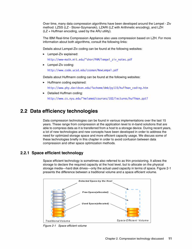
Space efficient technology is sometimes also referred to as thin provisioning. It allows the storage to declare the required capacity at the host level, but to allocate on the physical storage media—hard disk drives—only the actual used capacity in terms of space. Figure 2-1 presents the difference between a traditional volume and a space efficient volume.
Figure 2-1 Space efficient volume
D etected S pace by the H ost
Free S pace(allocated)
U sed S pace(allocated)
Trad itional Vo lum e S pace E ffic ien t Vo lum e
Chapter 2. Compression technology discussed 11

2.2.2 Flash Copy (space efficient)
Space efficient Flash Copy is a point-in-time copy of volume, is a technique that allows the creation of copies of volume data and data instances without multiplying the required space with the number of copies. This technology allows the copy to depend on the source with all the data that is in common. When data is changed from the original volume, those changes will be available and reflected only in the updated instance while the rest of the data will remain as a common foundation.
Figure 2-2 presents graphically a data volume and its dependency on a Flash Copy.
Figure 2-2 Space efficient Flash Copy
2.2.3 Easy Tiering
Easy Tiering is a technology that is optimizing the way data is placed across different types of drives (FC/SAS, SATA/SAS_NL, and SSDs). In current environments, the storage system configuration is done by using a rule set. Those rules are well known by a specialist and they usually refer to the result expected after configuring a storage system. The hardest part is to address, in a price/performance way, the capacity needs over the performance needs.
Usually when you need capacity, you add drives; and when you need performance, you add drives. There are a lot of situations when you need to add drives in order to accommodate a specific performance, although those drives are not needed in terms of capacity. In these situations, the infrastructure will be oversized in terms of capacity.
Volume A
Common Data
Data changed in volume A
Flash Copy of Volume A
Data originaly in volume A
12 Introduction to IBM Real-time Compression Appliances

IBM Easy Tier® (Figure 2-3) is a feature that is able to provide an optimized balance between capacity and performance. It does this by identifying specific hot zones and by moving them from slower drives to faster drives automatically. Thus you can profit from using a combination of SSD drives with much slower but higher capacity SATA drives, instead of using many more faster drives to accommodate the needed load.
Figure 2-3 Easy Tier data allocation
2.2.4 Archiving and space management
Archiving and space management, also known as Information Life-cycle Management (ILM) is a concept rather than a dedicated technology solution. It can be used in environments where you need to keep data over a long period of time and you need to optimize the space occupied on different storage types (tapes, hard disk drives, and so on). The old or not used data can be moved out of the production area and placed on a much cheaper support (that is, by moving data from enterprise storage systems to low end storage systems and then from hard drives to tapes). The historical information is usually kept in a database that holds metadata to provide accurate information about the managed data.
2.2.5 Data deduplication
The data deduplication mechanism identifies identical chunks of data within a storage container and keeps only one copy of each chunk, while all the other logically identical chunks will be pointed to this chunk. Over time, if a chunk repeats it self (like backups of the same file), depuplication can offer a high reduction rate of the data stored. There are various implementations of this method. One possibility is in-line deduplication and the other one is post-processing. In-line solutions (Figure 2-4) deduplicate information as it is stored. Post-processing solutions deduplicate data after the information is stored in the original format at certain time intervals.
Chapter 2. Compression technology discussed 13

Figure 2-4 Data deduplication
2.3 Data compression technologies
The compression of data has rapidly become a focus for the IT industry. Because of the different types of data and the reasons why data is compressed, two concepts are used:
� Reversible data compression: This method allows the information to be rebuilt completely with no impact on the quantity or quality of the original information.
� Irreversible data compression: This method synthesizes the information and keeps only the data that is needed. The original information cannot be rebuilt completely to its original form when the data is decompressed.
Examples of irreversible data compression include audio, image, video compression, reports, and graphics generated in order to visualize large amounts of data, statistics. One clear example can be a situation with the runners at the Olympic Games who manage to go under 10.1 seconds in the 100 meter speed running probe. We can say, for example, that 35% of the runners manage to go under 10.1 seconds and retain this value. But if we do not look at the input data where all runners have their time, we cannot say that runner “X” has that time.
In this way, reversible data compression offers the advantage of the possibility to recreate completely and accurately the input information. In comparison, the irreversible method offers only some specific information related to the original information.
Comparison: All the technologies presented in 2.2, “Data efficiency technologies” on page 11 are used to optimize the way that the available storage capacity is used. None of those technologies change information but rather optimize how this information is stored or how much of this information is duplicated within the storage system. Data compression technologies are able to interpret data. For that, they are able to provide storage optimization, both regarding the amount of data stored and the performance needed for the storage system used in back-end systems.
14 Introduction to IBM Real-time Compression Appliances

Because of the massive amounts of data and the calculation necessary for compressing data, there are two approaches: real-time compression and post-processing compression. These are their major characteristics:
� Real-time compression: This method processes the data before it is written to the storage device. The key advantage of this approach is that it reduces the storage resources required for a given data set. If done correctly, the capacity-reduction application will preserve the inherent performance of the storage environment. Data, already optimized, will be written to storage and mitigate the capacity explosion challenge at the point of origin. It accomplishes this by eliminating the need to allocate additional storage capacity as required with post-processing solutions. In addition, because this is primary storage, any compression technique has to be performed in real time and must maintain the high availability features of the existing storage system.
� Post-processing optimization: These solutions eliminate the need to deal with the performance issues in real time and usually do not have any advanced high availability capabilities. The challenge with post-processing optimization is that it uses storage resources for the capacity-reduction application, which causes a significant impact on storage I/O resources. Post-processing solutions require a read operation and pull a full copy of the original data to the storage; continue scanning the data, reading the data, and writing the optimized file; and then delete the original file.
In addition, when data deduplication is thrown into the equation, the pointer between the optimized file and its deduplicated file needs to be written to storage before the deletion of the original file. This is a very complex and I/O intensive process. It is also the case that when you want the optimized data, there must be enough space available on disk to uncompress it, which means you do not actually improve storage utilization.
It is important to keep in mind, when considering post-processing optimization techniques, that all optimization operations need to be scheduled carefully. Operations must be done during a time of day when there are free resources on the subsystem (non-production, non-backup windows). Also, operations must occur after a point in time when snapshots have been completed and newly optimized files have been written to disk. Managing a schedule such as this is next to impossible, and you risk not finding the time to optimize your capacity before you actually run out of disk space.
Over the years, IBM has introduced a series of reversible, real-time compression algorithms and solutions used in wide range of technologies:
� The LTO-DC algorithm used in IBM Linear Tape Open, formally known as LTO tape drives
� The Streaming Lossless Data Compression (SLDC) algorithm used in IBM Enterprise-class TS1140 tape
� The Adaptive Lossless Data Compression (ALDC) used by the IBM Information Archive for its disk pool collections
� The Random Access Compression Engine (RACE) used inside Real-time Compression Appliance
Chapter 2. Compression technology discussed 15

16 Introduction to IBM Real-time Compression Appliances

Chapter 3. Introduction to RTCA design
In this chapter, we discuss the main concepts used in the IBM Real-time Compression Appliance (RTCA), namely the Random Access Compression Engine (RACE) algorithm. We also examine the way the RTCA product manages to deliver high performance and the technology used for preserving data integrity.
3
© Copyright IBM Corp. 2013. All rights reserved. 17
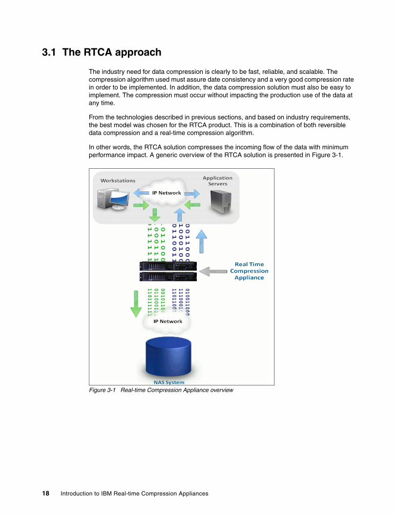
3.1 The RTCA approach
The industry need for data compression is clearly to be fast, reliable, and scalable. The compression algorithm used must assure date consistency and a very good compression rate in order to be implemented. In addition, the data compression solution must also be easy to implement. The compression must occur without impacting the production use of the data at any time.
From the technologies described in previous sections, and based on industry requirements, the best model was chosen for the RTCA product. This is a combination of both reversible data compression and a real-time compression algorithm.
In other words, the RTCA solution compresses the incoming flow of the data with minimum performance impact. A generic overview of the RTCA solution is presented in Figure 3-1.
Figure 3-1 Real-time Compression Appliance overview
18 Introduction to IBM Real-time Compression Appliances
3.2 IBM Real-time Compression
To understand the basic design of the IBM Real-time Compression technology, we need to review in detail the basics of modern compression techniques. These include the Lempel-Ziv algorithm and Huffman coding.
The IBM Real-time Compression Appliance (IBM RTCA) is based on a reversible data compression algorithm that operates in a real-time method.
The IBM RTCA product compresses data on initial write in order to assure that less data is stored on primary storage. Because of this, the storage system has to process less data, using less CPU overhead and lower disk spindles utilization. The storage system can therefore serve more requests from its read/write cache, while some reads can be served from the RTCA product’s read-ahead cache.
In addition to compressing data in real-time, the IBM RTCA product also enables its customers to non-disruptively compress existing data that is already saved to disk with the Compression Accelerator utility. Compression Accelerator is a high-performance and intelligent software application running on the IBM RTCA product which, by policy, allows users to compress data that has already been saved to disk while that data remains online and accessible by applications and end users.
The policies allow users to throttle how decompressed data gets compressed so as not to have an impact on existing storage performance. The ability to compress already stored data significantly enhances and accelerates the benefit to end users, allowing them to see a tremendous return on their IBM RTCA investment. On initial purchase of an IBM RTCA product, users can defer their purchase of new storage. As new storage needs to be acquired, IT purchases less than half of the “required” storage before compression. The IBM RTCA product enables IT to save on their overall storage investment.
3.3 IBM RTCA RACE technology
The IBM Random Access Compression Engine (RACE) technology is the core of IBM RTCA products for NAS. RACE technology is based on 35 patents that are not about compression. Rather, they define how to make industry standard LZ compression of primary storage operate in real-time and allow random access. The primary intellectual property behind this is our RACE engine. The IBM RACE engine sits on an appliance in front of any NFS or CIFS deployment, acting as an “intelligent cable” between the IP switch and the storage. This configuration is shown in Figure 3-1 on page 18. No software agents or drivers are required on clients or servers.
Chapter 3. Introduction to RTCA design 19

The RACE technology (see Figure 3-2) is made up of three components:
1. Random Access Compression Engine (RACE): Enables random-access data compression without compromising performance.
2. Unified Protocol Manager (UPM): Enables transparent support of multiple storage and network protocols, including CIFS and NFS.
3. Monitoring and Reporting Manager (MRM): Enables online storage compression trending, analysis, and reporting.
Figure 3-2 RACE technology overview
3.3.1 Random Access Compression Engine: RACE
The traditional compression technologies start from a constant file size and, after compression, the result is a variable file in terms of capacity. Because of this, when using large data chunks, the performance impact is high. However, when using small data chunks, although the performance impact is small, the compression ratio is also very small. Over time, there are many disadvantages that can occur. These include the need for garbage collection, poor performance while the volume of the data increases, or losing parts of metadata, such as the date of creation, date accessed, user rights, or modification dates. Another issue can be fragmentation in the target storage space. This occurs because after the file is stored in its original size, the result of compression is stored in a new zone and then the input is deleted.
The Random Access Compression Engine (RACE) starts from an unknown data stream and compresses data coming from the host. The resulting compressed file keeps all attributes from the original; metadata is not changed. Also, because of the in-line approach, there is no need at the storage level to write original data, read it, write the result of compression, and finally, delete the initial file. At the end, there will not be any garbage or fragmentation on the storage system. The performance needed at the storage level will be decreased because the writes and reads will be made only in compressed format instead of a complete one.
20 Introduction to IBM Real-time Compression Appliances

A logical overview of the Random Access Compression Engine is presented in Figure 3-3.
Figure 3-3 Random Access Compression Engine
RACE takes incoming data streams and compresses the data within these data requests, leaving the metadata intact, to the storage array. The data is stored in the array and the acknowledgement that the write has been committed is sent directly back from the array to the end user or application. This process flow is important because from a data availability perspective, it is imperative that it is the storage array that acknowledges the write commitment, not the IBM RTCA product. It is for this reason that the IBM RTCA product has no write cache. All storage commits come from the array, preserving the integrity of the data between the storage and the application.
As stated before, the IBM RTCA technology leverages industry standard LZ compression algorithms. The “secret sauce” is not the compression algorithms that the RTCA product uses to do its compression, but rather the manner in which that compression is accomplished. One of the key ways that the RTCA product is able to achieve its high compression ratios and performance is by compressing data utilizing random access techniques.
The benefits of compressing data using random access techniques are twofold. First, the ability to read or write only the blocks of the compressed file that require read or modification means faster access performance for these operations. If you only need to write a small piece of data in order to update a whole file, your storage performance is maximized. Second, because the RTCA product has this capability, updates to the file are accomplished in a way that does not disrupt the other blocks in the compressed file.
We are operating under the assumption that upstream data compression significantly reduces downstream data deduplication ratios. Therefore it is preferable to apply data deduplication technologies over decompressed data prior to performing a deduplicated backup. This can be true for data compressed with traditional techniques. But the unique, random access nature of the IBM RTCA product's compression preserves data deduplication ratios. This allows end users to experience maximum data optimization in both primary and downstream tiers.
Chapter 3. Introduction to RTCA design 21
3.3.2 Link Status Mirroring
In order for the IBM RTCA product to appear in the network as an “intelligent cable,” there needs to be technology to ensure that the system provides the same functionally to act like a cable even though it is a device in the network. This is achieved through Link Status Mirroring (LSM), which sits behind each cable in the data path. Let us suppose that any cable fails, or that any component in the data path fails. If so, the switch or storage or the I/O traffic coming into that cable, from either the sending or receiving end, will all need to be failed over to the other available link in the solution.
When a failure occurs and one link in the device is not available, LSM ensures that the other side of the link is also downed such that data traffic can be rerouted to the available link in the data path. This operation happens in microseconds to ensure the highest degree of availability to the data. Additionally, when the failure is fixed, and the link is restored, LSM also provides a mechanism to fail the link back to the predominant active link.
3.3.3 Unified Protocol Manager
One of the key components of RACE is the Unified Protocol Manager (UPM) that allows the IBM RTCA product to seat in line between the storage NAS (NFS and CIFS shares) and the user and to act as an “intelligent cable.”
This transparent behavior means there is no change required to the end user environment. Further, there are no changes required to storage, networking or applications. The IBM RTCA product does not require any changes to the existing infrastructure or to downstream processes such as snapshots, backup, replication, and archiving. The RTCA product enhances these environments because you are moving and storing less data.
The following use cases are examples:
� Snapshots: After you have installed the RTCA product, if your array allows you to take snapshots of your data, your snapshot data will also be compressed and be accessible, without any system changes to the server. The metadata, such as file permissions, size, ownership, and the Access Control List (ACL), are maintained in the compressed file.
� Conserving the file attributes: When a user performs a directory listing of the compressed data, the RTCA product reports back all of the actual file metadata. This is done as if the file was not compressed, including the file size and all of the ownership and permissions. By interpreting the file envelope and providing the native file attributes, the IBM RTCA product negates the need for applications to be changed in order to read the compressed data on disk. This means that there is no change required for IT, allowing the solution to fit seamlessly into the environment.
When operating system commands such as df are run on the storage subsystem, the IBM RTCA product does not mask the compressed file size. This allows the server to always know exactly how much free space there is for files, and if quotas are in use, they can be enforced. These functions truly make the IBM RTCA product fully transparent in the environment.
Space: The df command displays information about total space and available space on a file system.
22 Introduction to IBM Real-time Compression Appliances

3.3.4 Monitoring and Reporting Manager
Another component to the overall RACE technology is the Monitoring and Reporting Manager or MRM. The MRM enables online storage compression trending, analysis, and reporting. Further, MRM provides users with a host of services to efficiently manage and report on the IBM RTCA status and activities, and to quantify the benefits of the solution across the environment.
The MRM provides users standard interfaces such as SNMP, allowing visibility into appliance health and performance through numerous traps and “poll-able” objects. Downloadable SNMP MIB libraries allow end users to integrate IBM RTCA monitoring into their monitoring and reporting tool of choice. MRM also allows users to integrate LDAP with the IBM RTCA product, facilitating auditable login authorizations. In an HA configuration, MRM also automatically synchronizes the configuration setting between partner appliances to ensure the accuracy of configuration and streamline solution management.
In addition, MRM provides the users with the ability to select certain file types to include or exclude from compression as well as the ability to select shares to include or exclude from compression. MRM also allows users to see the amount of space saved by utilizing the IBM RTCA product. MRM provides the ability to select the file types to include or exclude from compression. But more importantly, in most cases, it selects which shares to include or exclude from compression.
3.4 Performance considerations
There are many factors that impact storage performance, including but not limited to these:
� Disk drives: Performance cannot be any faster in any system than the slowest mechanism in the chain. In storage, this is the mechanical movement of the disk drive. The greater the actuator arm has to travel, the slower the disk performance.
� I/O: The next consideration involves reads and writes, or I/O. The more reads and writes there are in a storage system, the more the storage system has to process these I/O requests. Also, it takes longer for the storage system to respond, and consequently, the the storage system is slower. The storage system is busy processing all of these I/O requests and moving the storage arm to read and write data. So it means that the storage CPU gets more loaded, and the response to extra storage requests gets slower.
� Cache: At the top of the storage array performance is its cache. Storage cache is very expensive; however, if configured properly for a given application, it can take a lot of the workload off of the disk, I/O, and CPU. It can provide faster response back to the end user or application requesting data. Data that lives in cache is served significantly faster than data that must be retrieved from disk.
In order for any storage compression solution to fit into this environment, it cannot negatively impact any of these functions. To be a good solution, it must enhance these functions.
Also, because there is less data being written to the storage array, there is less I/O. With less I/O, now there are more CPU cycles to process the given read and write requests.
Chapter 3. Introduction to RTCA design 23

Finally, by compressing data in front of the storage array, a net increase in effective cache size is achieved. Whatever the compression ratio is for your data, this compression ratio transcends to your storage cache. Cache is one of the most expensive components of a storage array, and also, cache tends to have the biggest impact on storage performance. So the more you can increase cache, the better performance users and applications will see.
Performing compression in real-time, before the data gets to the storage, has tremendous benefits to overall storage performance. It removes a lot of the hurdles that storage administrators face when considering compression as a technology for their primary storage.
For more best practices and performance considerations, see Chapter 6, “Performance considerations” on page 59.
3.5 Data integrity
As part of the solution design, IBM Real-time Compression has developed the Data Integrity Assurance architecture (DIA). The multitiered data protection it provides, built into every IBM Real-time Compression data compression appliance, is a quantum leap forward in guaranteeing data integrity.
To ensure 100% data integrity, the IBM Real-time Compression product line was developed having in mind the following goals:
� Preserving existing data integrity mechanisms in the storage array
� Preserving existing data integrity mechanisms in the network
� Verifying the reliability of storing and retrieving the compressed data
� Using the industry-proven Lempel-Ziv (LZ) lossless data compression algorithm
� Using error-correcting code (ECC) memory modules to ensure data integrity for memory access
This list describes how the IBM Real-time Compression Appliance integrates seamlessly into NAS environments, increasing the storage capacity, while assuring data integrity as follows:
� Preserving the data integrity mechanisms already in place in the network
� Providing mechanisms to guarantee the reliability of the compressed data through the IBM DIA Data Integrity Assurance® architecture
Tip: If your data is compressible by 3:1, IBM Real-time Compression provides the equivalent of increasing the size of your storage cache by the same ratio.
24 Introduction to IBM Real-time Compression Appliances

3.5.1 Data integrity at the network level
The IBM Real-time Compression Appliance preserves data integrity mechanisms at the protocol and storage levels.
Performing verification checks at the network protocol layer ensures data integrity during transmission between components in your network. These checks are cyclic redundancy check (CRC) checksum mechanisms that verify data integrity during transmission of data between components. A graphical representation is shown in Figure 3-4.
Figure 3-4 Network data integrity mechanism
3.5.2 Data integrity at the protocol layer
When you install the IBM Real-time Compression Appliance (Figure 3-5), the checksum mechanisms employed in your network continue to function as usual. The IBM Real-time Compression Appliance manages two sets of checksum mechanisms:
� Checksums on the uncompressed data in the connection between the IBM Real-time Compression Appliance and the switch
� Checksums on the compressed data in the connection between the IBM Real-time Compression Appliance and the storage array
Chapter 3. Introduction to RTCA design 25
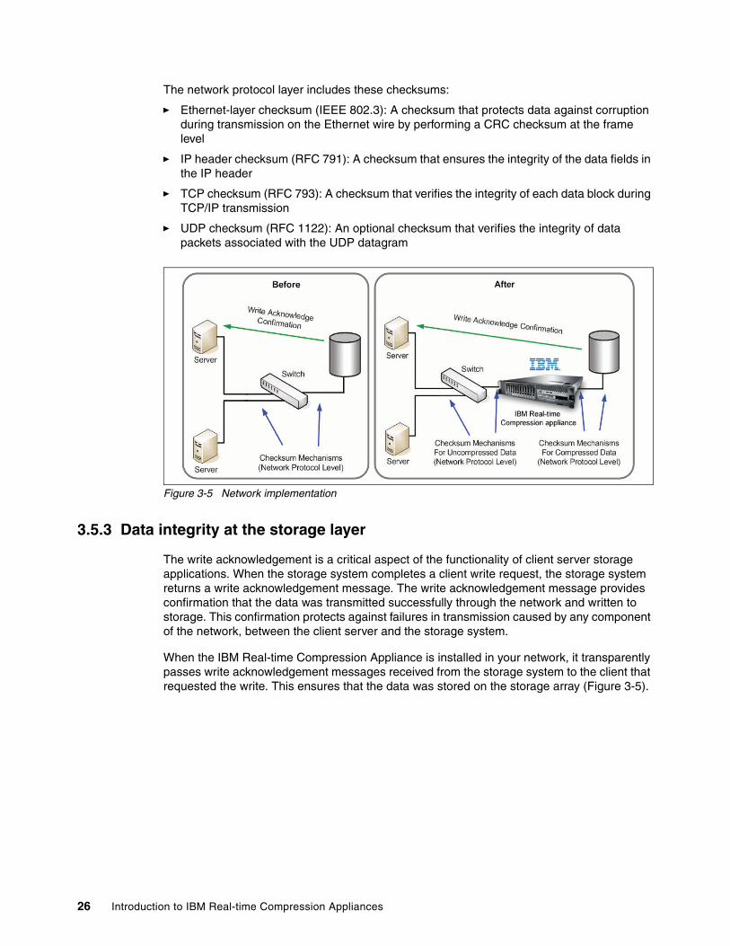
The network protocol layer includes these checksums:
� Ethernet-layer checksum (IEEE 802.3): A checksum that protects data against corruption during transmission on the Ethernet wire by performing a CRC checksum at the frame level
� IP header checksum (RFC 791): A checksum that ensures the integrity of the data fields in the IP header
� TCP checksum (RFC 793): A checksum that verifies the integrity of each data block during TCP/IP transmission
� UDP checksum (RFC 1122): An optional checksum that verifies the integrity of data packets associated with the UDP datagram
Figure 3-5 Network implementation
3.5.3 Data integrity at the storage layer
The write acknowledgement is a critical aspect of the functionality of client server storage applications. When the storage system completes a client write request, the storage system returns a write acknowledgement message. The write acknowledgement message provides confirmation that the data was transmitted successfully through the network and written to storage. This confirmation protects against failures in transmission caused by any component of the network, between the client server and the storage system.
When the IBM Real-time Compression Appliance is installed in your network, it transparently passes write acknowledgement messages received from the storage system to the client that requested the write. This ensures that the data was stored on the storage array (Figure 3-5).
26 Introduction to IBM Real-time Compression Appliances
3.6 Storage advantages
Installing the IBM Real-time Compression Appliance in a storage configuration provides unmatched benefits to the storage environment:
� Primary storage compression: The IBM Real-time Compression Appliance compresses the data before it reaches the storage unit. This provides unique advantages over other storage capacity solutions:
– Improves response time: Reduces traffic to and from the storage system.
– Reduces the storage system’s read/write activity: Compressing data before it reaches the storage system enables the storage system to store and provide data with less read and write activity.
– Read gains: Increases the effective size of the storage read cache, improving the performance of read operations. Storage system read performance is greatly influenced by the cache hit ratio. Better use of the read cache reduces the need for disk head movement, which is slower than cache access. Because IBM Real-time Compression compresses the data before it reaches the storage system, the effective size of the read cache increases. The read cache improvement is proportionate to the compression ratio.
– Write gains: Increases the effective size of the write cache, improving the performance of write operations. Storage systems typically cache write operations to enable immediate acknowledgement to clients and reduce response time. The size of the write cache significantly impacts the throughput of write operations to storage. The IBM Real-time Compression Appliance compresses the data before it reaches the write cache, so the effective size of the cache increases proportionately with the compression ratio.
� Reduces infrastructure costs: Using IBM Real-time Compression Appliances reduces your storage capacity by up to 80 percent, and helps to eliminate the expensive infrastructure requirements of expanding your storage footprint.
� No changes or server resources required: The IBM Real-time Compression Appliance provides storage gains with the advantages of self-contained, appliance simplicity:
– No need to change the storage system configuration– No need to change your workflow– No server resources used
Compared to proprietary array compression or deduplication, the IBM Real-time Compression Appliance has significant advantages as well:
� Reduces IO workload� Reduces CPU workload� Cache multiplying effect� Array vendor neutral
As a final benefit, we might say that the IBM Real-time Compression Appliance can break the IOPS per terra-byte ratio. As we will be able to get larger drives, we still are limited to the physical performance capacity of the drives.
Chapter 3. Introduction to RTCA design 27

28 Introduction to IBM Real-time Compression Appliances
Chapter 4. Hardware and software components
In this chapter, we provide an overview of the IBM Real-time Compression Appliance (RTCA) hardware and software components.
This chapter outlines base model configurations and the technical specifications, such as number of ports, memory capacity, and the physical attributes of the products.
4
© Copyright IBM Corp. 2013. All rights reserved. 29

4.1 Base model configurations
Currently, the IBM RTCA product portfolio consists of one model that is configured with base and optional features.
These details are valid at the time of writing, but for current details, see this website:
http://www.ibm.com/systems/storage/network/rtc/
4.1.1 IBM Real-time Compression Appliance STN7800 (2452-780)
The IBM Real-time Compression Appliance STN7800 is a new model, based on standard IBM System x3650 M4, created with innovative design and flexibility and optimized for the best performance.
With redundant hot-swap fans, disks, and power supplies, the STN7800 provides a resilient architecture that is ideal for business-critical applications. Predictive Failure Analysis and light path diagnostics provide advanced warning on power supplies, fans, voltage regulator modules (VRMs), disks, processors, and memory. Redundant hot-swap components can help you more easily replace failures without shutting down your system.
The STN7800 is a 2U appliance. It comes equipped with 1-Gb copper Ethernet, 10 Gb optical Ethernet (10GBASE-SR), or both ports configured as:
� Four 10-GbE optical ports and eight 1-GbE copper ports� Eight 10-GbE optical ports� Sixteen 1-GbE copper ports (optional Feature Code)
In addition, the STN7800 is equipped with a management port. This port configuration is factory-set when the appliance is ordered. Each NAS requires at least two cables. One cable connects the NAS to theSTN7800, and another cable connects the STN7800 to the LAN switch for that NAS.
� IBM System x3650 M4 7915� Dual Intel Xeon E5-2680 processors� Twelve 8 GB DDR3 1333 MHz LP RDIMM or eighteen 16GB DDR3 1333MHz LP RDIMM� Dual 300 GB 10 K 6-Gbps SAS HDD� UltraSlim Enhanced SATA DVD-ROM� Dual redundant 900 W ac high-efficiency power supplies� Integrated quad Gigabit Ethernet ports for high I/O capacity� Two optional embedded 10 GbE ports� Two C13-C14 PDU cables� One 3 m Blue Cat6a cable� One 3 m RS-232 cable
The eighteen 16 GB DDR3 1333MHz LP RDIMM are order through RPQ Number:8S1242
Optional NIC feature:
� Dual Port 10GbE SFP+ adapter
30 Introduction to IBM Real-time Compression Appliances

4.2 Front-panel components
The STN7800 has its front panel depicted in Figure 4-1.
Figure 4-1 STN7800 front-panel components
The front panel includes these components:
� Operator information panel:
This panel contains the following controls, LED indicators, and connectors:
– Power control button: Press this button to manually switch the server on and off.
– Power on LED:
• Off: Power is not present; or the power supply or the LED itself failed.
• Flashing rapidly (4 times per second): The server is turned off and is not ready to be turned on. The power control button is disabled, which continues approximately 5-10 seconds.
• Flashing slowly (once per second): The server is turned off and is ready to be turned on. You can press the power control button to turn on the server.
– Lit: The server is turned on.
– Ethernet activity LEDs: When any of these LEDs is lit, it indicates that the appliance is transmitting to or receiving signals from the Ethernet LAN that is connected to the Ethernet port corresponding to that LED.
– System locator button/LED: Use this blue LED to visually locate the server among other servers.
� USB port: Connect a USB keyboard, or other USB device, to either of these connectors.
� Hot-swappable RAID-1 mirrored hard disk drives that store the RTCA software and appliance configuration.
4.3 Rear-panel components
This section describes the rear panel components of the RTCA product. Figure 4-2 shows the rear view of the STN7800 with 8 10GbE optical ports.
Chapter 4. Hardware and software components 31

Figure 4-2 STN7800 rear panels
The STN7800 can have different rear panels. Nevertheless, many of the ports and connections serve the same functions:
� STN7800 with 16 x 1GbE copper ports: Data ports are numbered eth0-eth15. The sequence begins at slot 2, and continues to slot 3, 5, and 6.
� STN7800 with 4 x 10GbE optical and 8 x 1GbE copper ports: Data ports are numbered eth0-eth11. The sequence begins at slot 2, and continues to slot 3, 5, and 6.
� STN7800 with 8 x 10GbE optical ports: Data ports are numbered eth0-eth7. The sequence begins at slot 2, and continues to slot 3, 5, and 6.
� Serial console port (RJ-45): Connects a terminal directly to the compression appliance to have access to the hardware interface (IMM).
� Management port: Configures the compression appliance using the web interface. In general, you need to connect to the administration tool through the management port.
� Power supply units (PSUs): Dual power supply units provide power to the STN7800. If a single power supply malfunctions or stops receiving power, a beeping sound is emitted. The remaining PSU automatically senses the failure and maintains uninterrupted power to the appliance.
� Power supply units (PSUs): There are two power supply units. If a single power supply malfunctions or stops receiving power, a beeping sound is emitted, informing you that there is a problem. The other power supply unit automatically senses the failure and maintains uninterrupted power to the appliance.
� AC connector: Each power supply has its own ac connector. Connect each power supply unit to a separate power source to maintain redundancy and high availability
� PSU cable lock: This feature ensures that the power source cables remain securely attached to the ac connectors.
4.4 Technical specifications
This section discusses the technical specifications for the RTCA model STN780.
4.4.1 Physical specifications
Table 4-1 lists the physical specifications for model STN7800.
32 Introduction to IBM Real-time Compression Appliances

Table 4-1 Network interfaces of the RTCA product
4.4.2 Technical specifications
Technical specifications for model STN7800 are shown in Figure 4-2.
Table 4-2 Technical specifications for model STN7800
4.4.3 Operating environment
Operating environment specifications for model STN7800 are shown in Figure 4-3.
Table 4-3 Operating environment for model STN7800
Network interfaces STN7800 (with feature#2001) a
a. At configuration time, one of these features must be selected: 2001, 2005, or 2015.
STN7800 (with feature#2005)a
STN7800 (with feature#2015)a
1 Gbps copper ports 16 8 -
10 Gbps copper ports - 4 8
1 Gbps copper management port
1 1 1
Feature Value
Operating weight Maximum configuration: 30 kg (65 lb)
Form factor 2 rack units
Dimensions width 445.0 mm (17.5 in)
Depth 746.0 mm (29.4 in)
Height 86.5 mm (3.4 in)
Power 100-240V ac
50-60 Hz
Maximum configuration: 1.02 kVA (with 900 Watts PSU)
Hot-swap PSUs
Thermal Output 525-3480 BTU / hr.
Feature Value
Temperature server on 10° to 35° degrees C (50° to 95° degrees F)
Server off 5° to 45° degrees C (41° to 113° degrees F)
Humidity server on/off: 8% to 80%
Acoustical noise emissions: Declared sound power, idle
6.4 bell
Acoustical noise emissions: Declared sound power, operating
6.6 be
Compliance RoHS-compliant
Chapter 4. Hardware and software components 33
4.4.4 Supported clients and servers
The full interoperability matrix for IBM System Storage Real-time Compression Appliances is available at the IBM System Storage Interoperation Center (SSIC) website:
http://www.ibm.com/systems/support/storage/ssic/interoperability.wss
4.5 Software components
Three main software components enable the IBM RTCA product to perform storage compression:
� Random Access Compression Engine (RACE): Enables data compression without compromising performance.
� Unified Protocol Manager: Enables transparent support of multiple storage and network protocols, including CIFS and NFS.
� Monitoring and Reporting Manager: Enables online storage compression management and reporting.
4.6 RTCA network terminology
The RTCA product acts as an “intelligent cable” between the Ethernet switch and the NAS storage server. To provide network connectivity, having bonds and bridges is necessary.
4.6.1 Bond
A bond combines physical RTCA ports to a single virtual interface; a bond is the vehicle for port aggregation. The RTCA product supports the common port aggregation protocols EtherChannel and 802.3ad (LACP). Also, you can create active backup bonds.
4.6.2 Bridge
A bridge combines two physical interfaces or bonds to establish a network connection between the Ethernet switch and the NAS storage server. For every bridge, a new IP address must be configured. This IP address is used by the RTCA product to poll the NAS shares and exports.
34 Introduction to IBM Real-time Compression Appliances

Part 2 Implementation planning
In this part of the book, we discuss all details necessary for a successful RTCA implementation. We show how to plan your implementation, install and configure it, and integrate the system with host operating systems.
Part 2
© Copyright IBM Corp. 2013. All rights reserved. 35

36 Introduction to IBM Real-time Compression Appliances

Chapter 5. Solution design and implementation planning
In this chapter, we offer a planning guide to provide proper solution design. We describe the physical and logical installation of the IBM Real-time Compression Appliance (RTCA), as well as validation and testing of the final installation and reporting considerations.
5
© Copyright IBM Corp. 2013. All rights reserved. 37

5.1 Introduction to installation, reporting, validation, testing
RTCA physical installation includes and addresses the following items:
� Solution requirements� Architectural planning� Network planning� Antivirus services considerations� Network considerations
Logical installation of the RTCA includes the following items:
� Configuration planning� High-availability for the compression appliances
Reporting considerations include information regarding the following items:
� Capacity consumption� File types� Capacity growth
Validation and testing of the final installation includes the following activities:
� Checking cabling, hardware, power on, and system logs� Meeting known memory limitations for NFS and CIFS
5.2 Physical installation
This section describes the planning of the physical RTCA installation.
5.2.1 Solution requirements
The following list is an outline of important solution requirements:
� NAS storage platform: The IBM Real-time Compression Appliance (RTCA) product supports only NAS protocols. Ensure that your Storage Server and required NAS protocols are supported. Information about supported features is at the following website:
http://www.ibm.com/support/entry/portal
� Data type: Be sure to identify compressible data before starting the configuration of the RTCA product.
� Capacity: Be sure to have enough capacity so that the solution is cost-effective. From experience, in most cases this is more than 20 TB of NAS data.
� Growth rate: Having a negligible annual growth rate is not what you want. The higher the growth rate, the more cost-effective the RTCA product will be.
38 Introduction to IBM Real-time Compression Appliances

5.2.2 Architectural planning
Architectural planning for RTCA solutions involves, physical installation and cabling, network interfaces, rack considerations, cables and ports, and understanding physical bypass.
Physical installation and cabling considerations Evaluate physical and cabling considerations.
Network interfaces Table 5-1 lists the three network options of the RTCA product.
Table 5-1 Network interfaces
Feature code 1010 or feature code 1001 must be included in the initial order of STN7800.
Rack considerations IBM RTCA hardware must be installed in a standard 19-inch rack by using the rack mounting hardware provided with the machine. The rack cabinet must have a 2U slot available for each RTCA product.
Cables and ports Your network cables must be unplugged from current storage, and plugged into the compression appliance. IBM supplies cables that go from the compression appliance to the storage:
� Feature code 3003: 3m Green Cat5e cable:
This feature provides one 3-meter Green Cat5e cable with RJ-45 connectors for 1-Gb Ethernet connections.
� Feature code 3705: 5m LC-LC optical cable:
This feature provides one 5-meter LC-LC Optical cable for 10-Gb Ethernet connections.
If you do not purchase cables from IBM, you must have an additional set of network cables to connect the RTCA product with your NAS storage server.
If the NAS storage is connected with eight 1-Gb copper cables to one Ethernet switch, you will need, in additional, eight 1-Gb copper cables and one 1-Gb copper cable for the management port for installing the RTCA product. Therefore, only one additional network port per RTCA product is required on the Ethernet switch.
Network interfaces STN6500 STN7800with feature code 1001a
a. Feature code 1001: 4x10Gb and 8x1Gb Ethernet ports; this feature provides both 1Gb and 10Gb Ethernet configurations.
STN7800with feature code 1010b
b. Feature code 1010: 8x10Gb Ethernet ports; this feature provides only 10Gb configurations.
1 Gbps copper ports 16 8 -
10 Gbps copper ports - 4 8
1 Gbps copper management port
1 1 1
Chapter 5. Solution design and implementation planning 39
Physical bypass Under normal conditions, bypassing the RTCA product for any Ethernet traffic is unnecessary.
5.2.3 Network planning
For proper solution design, you should understand networking concepts and terms that are associated with the RTCA product. You need to know about certain switches, as well as how to plan the physical connection.
RTCA network terminology The RTCA product acts as an “intelligent cable” between the Ethernet switch and the NAS storage server. To provide network connectivity, having bonds and bridges is necessary.
Bond A bond combines physical RTCA ports to a single virtual interface; a bond is the vehicle for port aggregation. The RTCA product supports the common port aggregation protocols EtherChannel and 802.3ad (LACP). Also, you can create active backup bonds.
Bridge A bridge combines two physical interfaces or bonds to establish a network connection between the Ethernet switch and the NAS storage server. For every bridge, a new IP address must be configured. This IP address is used by the RTCA product to poll the NAS shares and exports.
Tips:
� To avoid direct access to compressed data by clients, without bypassing the RTCA product, the best approach is to connect all network interfaces of the NAS storage server with the RTCA product.
� If you have available Ethernet ports on your NAS storage server and want to use these ports for iSCSI or replication purposes, at these Ethernet ports, all NAS protocols must be deactivated.
40 Introduction to IBM Real-time Compression Appliances

The general use of bridges and bonds is illustrated in Figure 5-1.
Figure 5-1 General use of bonds and bridges
Logical interfaces If your NAS storage system is configured with port aggregation, look at the port aggregation configuration and document the allocation of virtual interfaces to physical interfaces. Preferably, adapt the aggregated physical interfaces of your NAS storage server to corresponding bonds at your RTCA product (all physical interfaces of an aggregated interface will be in the same bond).
Example 5-1 shows the configuration of types of virtual interfaces of an IBM System Storage N series controller. The physical interfaces e0a and e0c are trunked by vifa as a multi-mode VIF. The physical interfaces e0b and e0d are trunked by vifb as another multi-mode VIF. Both vifa and vifb are configured as members in a second level VIF vif1 as a single mode VIF.
In an HA configuration, you must use one bond for vifa at the first RTCA product and one bond for vifb at the second RTCA product. Both bonds will be bridged to the corresponding bonds, which include the Ethernet connection to the switch. The VIF configuration remains unchanged at the N series system.
Example 5-1 Virtual interface configuration of N series with four physical interfaces
bran1> vif statusdefault: transmit 'IP Load balancing', VIF Type 'multi_mode', fail 'log'vifa: 2 links, transmit 'Round-Robin Load balancing', VIF Type 'multi_mode' fail'default'VIF Status Up Addr_settrunked: vif1up:e0a: state up, since 23Mar2011 15:24:49 (22:18:23)mediatype: auto-1000t-fd-upflags: enabled
Chapter 5. Solution design and implementation planning 41
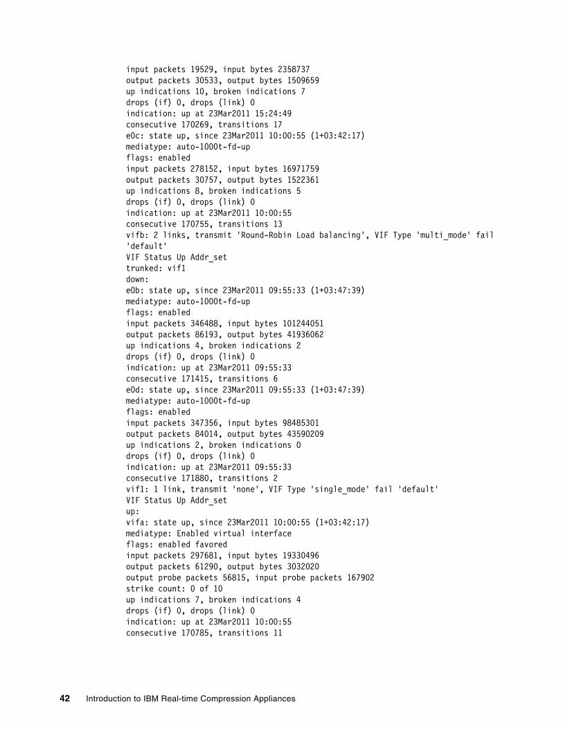
input packets 19529, input bytes 2358737output packets 30533, output bytes 1509659up indications 10, broken indications 7drops (if) 0, drops (link) 0indication: up at 23Mar2011 15:24:49consecutive 170269, transitions 17e0c: state up, since 23Mar2011 10:00:55 (1+03:42:17)mediatype: auto-1000t-fd-upflags: enabledinput packets 278152, input bytes 16971759output packets 30757, output bytes 1522361up indications 8, broken indications 5drops (if) 0, drops (link) 0indication: up at 23Mar2011 10:00:55consecutive 170755, transitions 13vifb: 2 links, transmit 'Round-Robin Load balancing', VIF Type 'multi_mode' fail'default'VIF Status Up Addr_settrunked: vif1down:e0b: state up, since 23Mar2011 09:55:33 (1+03:47:39)mediatype: auto-1000t-fd-upflags: enabledinput packets 346488, input bytes 101244051output packets 86193, output bytes 41936062up indications 4, broken indications 2drops (if) 0, drops (link) 0indication: up at 23Mar2011 09:55:33consecutive 171415, transitions 6e0d: state up, since 23Mar2011 09:55:33 (1+03:47:39)mediatype: auto-1000t-fd-upflags: enabledinput packets 347356, input bytes 98485301output packets 84014, output bytes 43590209up indications 2, broken indications 0drops (if) 0, drops (link) 0indication: up at 23Mar2011 09:55:33consecutive 171880, transitions 2vif1: 1 link, transmit 'none', VIF Type 'single_mode' fail 'default'VIF Status Up Addr_setup:vifa: state up, since 23Mar2011 10:00:55 (1+03:42:17)mediatype: Enabled virtual interfaceflags: enabled favoredinput packets 297681, input bytes 19330496output packets 61290, output bytes 3032020output probe packets 56815, input probe packets 167902strike count: 0 of 10up indications 7, broken indications 4drops (if) 0, drops (link) 0indication: up at 23Mar2011 10:00:55consecutive 170785, transitions 11
42 Introduction to IBM Real-time Compression Appliances
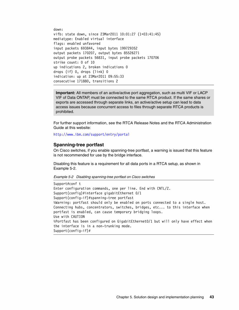
down:vifb: state down, since 23Mar2011 10:01:27 (1+03:41:45)mediatype: Enabled virtual interfaceflags: enabled unfavoredinput packets 693844, input bytes 199729352output packets 170207, output bytes 85526271output probe packets 56831, input probe packets 170706strike count: 0 of 10up indications 2, broken indications 0drops (if) 0, drops (link) 0indication: up at 23Mar2011 09:55:33consecutive 171880, transitions 2
For further support information, see the RTCA Release Notes and the RTCA Administration Guide at this website:
http://www.ibm.com/support/entry/portal
Spanning-tree portfastOn Cisco switches, if you enable spanning-tree portfast, a warning is issued that this feature is not recommended for use by the bridge interface.
Disabling this feature is a requirement for all data ports in a RTCA setup, as shown in Example 5-2.
Example 5-2 Disabling spanning-tree portfast on Cisco switches
Support#conf tEnter configuration commands, one per line. End with CNTL/Z.Support(config)#interface gigabitEthernet 0/1Support(config-if)#spanning-tree portfast%Warning: portfast should only be enabled on ports connected to a single host. Connecting hubs, concentrators, switches, bridges, etc... to this interface when portfast is enabled, can cause temporary bridging loops.Use with CAUTION%Portfast has been configured on GigabitEthernet0/1 but will only have effect when the interface is in a non-trunking mode.Support(config-if)#
Important: All members of an active/active port aggregation, such as multi VIF or LACP VIF of Data ONTAP, must be connected to the same RTCA product. If the same shares or exports are accessed through separate links, an active/active setup can lead to data access issues because concurrent access to files through separate RTCA products is prohibited.
Chapter 5. Solution design and implementation planning 43

Planning the physical connectionBefore you begin creating bridges and bonds, document the existing cabling diagram to determine which RTCA ports will be used to bring the switch-to-RTCA and the RTCA-to-NAS connection together.
Consider at least two possible ways for planning the physical connections. That is, the paired cables (the cable from the switch to RTCA and the cable from NAS) can reside as follows:
� Reside on separate PCI cards on RTCA� Reside on the same PCI card on RTCA
The second option (reside on the same PCI card on RTCA) is described 5.2.4, “Antivirus services considerations” on page 44 for the following reasons:
� From experience with PCI card problems in IBM Series x servers, we can confirm that the difference between the first and second option, for safety reasons, is minimal.
� The second option offers easier cabling interface connections and an easier logical environment perception.
5.2.4 Antivirus services considerations
In many NAS environments, the antivirus scanning activities are off-loaded for better scalability and performance. NAS vendors often advise having a dedicated physical network connection or dedicated VLAN configuration to transmit data from the NAS storage server to the antivirus server.
A highly preferred approach is to configure your physical network with NAS storage and the RTCA product, thus all data passes the RTCA product. If you configure a physical bypass of the RTCA product, compressed files will be transmitted to the antivirus server and malicious virus code will never be detected. If necessary, you can configure a dedicated bridge to separate the antivirus scanning traffic from all other network traffic.
44 Introduction to IBM Real-time Compression Appliances

An example of an antivirus configuration is illustrated in Figure 5-2.
Figure 5-2 Antivirus server in an RTCA environment
5.2.5 Network considerations summary
The following network considerations are important:
� Bridges connecting between the network and storage:
Each side of a bridge must be connected to either a network switch or an NAS storage server interface. Do not connect the two sides of the bridge to the network switch; this method creates a network loop that can affect service to users.
� Direct connection to the NAS:
The Link State Mirroring (LSM) is monitoring the network link status and automatically mirrors this status between the bridge interfaces. Connecting active components such as link converters or powered patch panels in between the appliance and the NAS storage server can cause the LSM mechanism to fail. Therefore, this approach is not supported.
� Number of network interface ports:
The compression appliance acts a bridge between two “sides,” so the number of required ports is 50% higher, of the total number of links that are configured in the NAS storage server. For example, if an N series system is configured with four 1-Gb links, a total of eight 1-Gb links will be required on the RTCA product to support this configuration.
In addition, the total number of links must support the expected aggregate throughput. For example, a particular NAS storage server is expected to provide approximately 500 MBps total throughput. Because each 1-Gb link provides approximately 80 - 100 MBps, in this environment, the best approach is to configure at least five bridges.
� Number of bridges:
Up to eight physical bridges can be configured on a single appliance, and up to 128 bridges configured with VLAN tagging (802.1q).
Chapter 5. Solution design and implementation planning 45
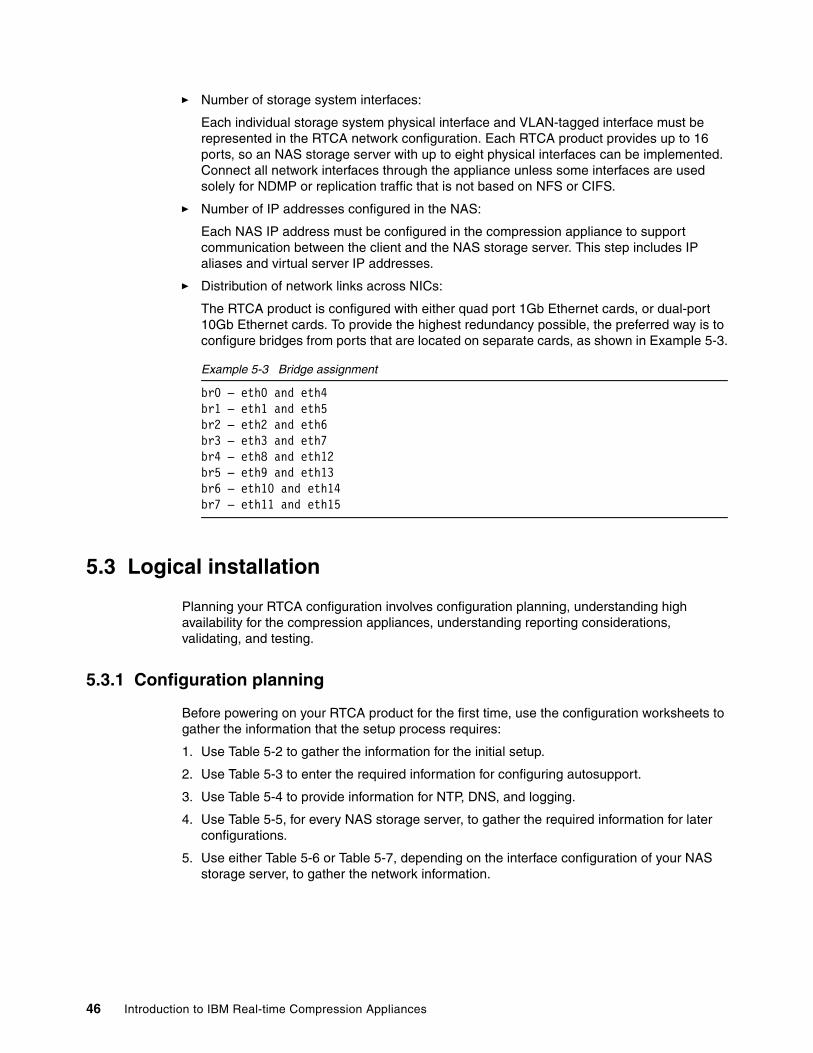
� Number of storage system interfaces:
Each individual storage system physical interface and VLAN-tagged interface must be represented in the RTCA network configuration. Each RTCA product provides up to 16 ports, so an NAS storage server with up to eight physical interfaces can be implemented. Connect all network interfaces through the appliance unless some interfaces are used solely for NDMP or replication traffic that is not based on NFS or CIFS.
� Number of IP addresses configured in the NAS:
Each NAS IP address must be configured in the compression appliance to support communication between the client and the NAS storage server. This step includes IP aliases and virtual server IP addresses.
� Distribution of network links across NICs:
The RTCA product is configured with either quad port 1Gb Ethernet cards, or dual-port 10Gb Ethernet cards. To provide the highest redundancy possible, the preferred way is to configure bridges from ports that are located on separate cards, as shown in Example 5-3.
Example 5-3 Bridge assignment
br0 – eth0 and eth4br1 – eth1 and eth5br2 – eth2 and eth6br3 – eth3 and eth7br4 – eth8 and eth12br5 – eth9 and eth13br6 – eth10 and eth14br7 – eth11 and eth15
5.3 Logical installation
Planning your RTCA configuration involves configuration planning, understanding high availability for the compression appliances, understanding reporting considerations, validating, and testing.
5.3.1 Configuration planning
Before powering on your RTCA product for the first time, use the configuration worksheets to gather the information that the setup process requires:
1. Use Table 5-2 to gather the information for the initial setup.
2. Use Table 5-3 to enter the required information for configuring autosupport.
3. Use Table 5-4 to provide information for NTP, DNS, and logging.
4. Use Table 5-5, for every NAS storage server, to gather the required information for later configurations.
5. Use either Table 5-6 or Table 5-7, depending on the interface configuration of your NAS storage server, to gather the network information.
46 Introduction to IBM Real-time Compression Appliances
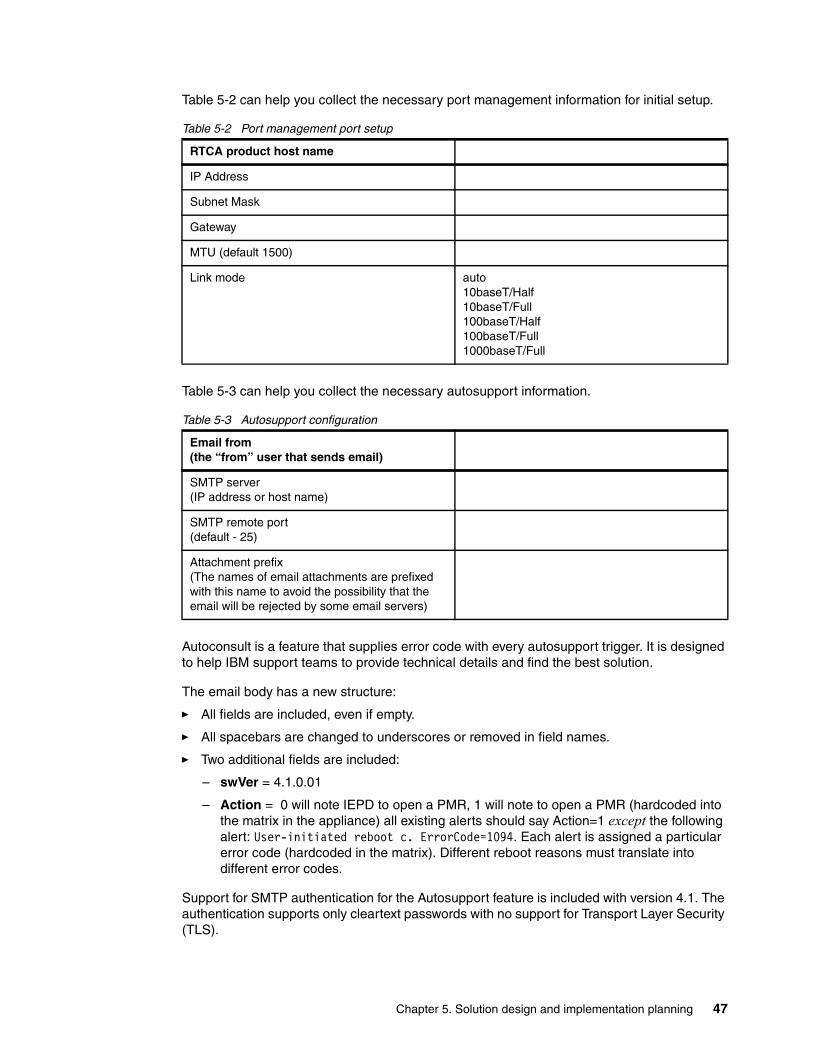
Table 5-2 can help you collect the necessary port management information for initial setup.
Table 5-2 Port management port setup
Table 5-3 can help you collect the necessary autosupport information.
Table 5-3 Autosupport configuration
Autoconsult is a feature that supplies error code with every autosupport trigger. It is designed to help IBM support teams to provide technical details and find the best solution.
The email body has a new structure:
� All fields are included, even if empty.
� All spacebars are changed to underscores or removed in field names.
� Two additional fields are included:
– swVer = 4.1.0.01
– Action = 0 will note IEPD to open a PMR, 1 will note to open a PMR (hardcoded into the matrix in the appliance) all existing alerts should say Action=1 except the following alert: User-initiated reboot c. ErrorCode=1094. Each alert is assigned a particular error code (hardcoded in the matrix). Different reboot reasons must translate into different error codes.
Support for SMTP authentication for the Autosupport feature is included with version 4.1. The authentication supports only cleartext passwords with no support for Transport Layer Security (TLS).
RTCA product host name
IP Address
Subnet Mask
Gateway
MTU (default 1500)
Link mode auto10baseT/Half10baseT/Full100baseT/Half100baseT/Full1000baseT/Full
Email from(the “from” user that sends email)
SMTP server(IP address or host name)
SMTP remote port(default - 25)
Attachment prefix(The names of email attachments are prefixedwith this name to avoid the possibility that theemail will be rejected by some email servers)
Chapter 5. Solution design and implementation planning 47

The GUI is extended by two options: SMTP User and SMTP Password. The options are shown in Figure 5-3.
Figure 5-3 Autisupport SMTP options
In addition, the command-line interface (CLI) has an extended parameter for the support command:
support [-su SMTPUser] [-sp SMTPPassword]
Table 5-4 can help you collect the miscellaneous information.
Table 5-4 Miscellaneous NTP and DNS configuration information
Table 5-5 can help you collect the necessary NAS information.
Table 5-5 NAS storage configuration: one table for each NAS storage server IP address
IP address NTP server 1
IP address NTP server 2
IP address remote syslog server
DNS domain
DNS search list
DNS name server IP address
Storage system name
Storage Vendor
Storage IP address
48 Introduction to IBM Real-time Compression Appliances

Table 5-6 can help you collect the necessary physical interface information.
Table 5-6 NAS storage physical interfaces to bridge directly switch - one table per interface
Table 5-7 can help you collect the virtual interface information.
Table 5-7 NAS storage virtual interface configuration - one table per virtual interface
5.3.2 High availability for the compression appliances
Among many possible design solutions, decide which one is important and which will be used before implementing RTCA appliance. The solution in question is a high availability solution for the compression appliance.
Four high-availability configurations are possible. They are listed here and described in the following section, for both before and after connecting the IBM Real-time Compression Appliance products. The manner in which the compression appliance preserves the high availability features of the NAS is illustrated in the configuration diagrams:
� Active/passive path failover� Active/active link aggregation� Path failover using two switches� Clustered environment (preferred configuration)
Active/passive path failoverThe active/passive path failover is configured according to a single NAS storage controller, which uses link aggregation with two or more physical interfaces. Only one link can be active at any particular time. A standby link is activated only if the NAS storage controller detects a fault in the active link. That is when all traffic goes through the new link that was activated.
Name of the interface
IP address for the bridge
Name of virtual interface
Member of virtual interface (physical interfaces)
Type multi (EtherChannel)multi (802.3ad LACP)single (active-backup)
IP address for the bridge
Chapter 5. Solution design and implementation planning 49

Figure 5-4 shows an active/passive path failover configuration without RTCA (on the left) and with RTCA (on the right).
Figure 5-4 Active/passive path failover: without and with a compression appliance
Use the following steps to configure active/passive path failover:
1. Test the NAS and switch for support of active/passive (failover) in direct connection mode.
2. Connect two network cables from the compression appliance to the NAS.
3. Connect two network cables from the compression appliance to the network switch.
4. By using the compression appliance web interface, create two bonds, one for the NAS and one for the network, each holding two physical interfaces.
5. Configure the mode on both bonds as active/passive.
6. Configure a bridge STN-1 BR-0 with bond0 and bond1 as members.
7. Configure the file server.
8. Start the compression engine.
9. Continue with the standard configuration.
Active/active link aggregationThe active/passive path failover is also configured according to a single NAS storage controller, which uses link aggregation with two or more physical interfaces. All links can be, at the same time, active and connected to a switch that supports aggregation through multiple port connections.
The switch is what determines the way in which incoming packets will be forwarded to the NAS storage controller. If a link in the aggregate shuts down, the remaining links that are active share the load and traffic that is supposed to be in the NAS storage controller, which then goes through the remaining active interfaces.
50 Introduction to IBM Real-time Compression Appliances
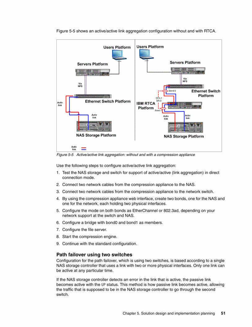
Figure 5-5 shows an active/active link aggregation configuration without and with RTCA.
Figure 5-5 Active/active link aggregation: without and with a compression appliance
Use the following steps to configure active/active link aggregation:
1. Test the NAS storage and switch for support of active/active (link aggregation) in direct connection mode.
2. Connect two network cables from the compression appliance to the NAS.
3. Connect two network cables from the compression appliance to the network switch.
4. By using the compression appliance web interface, create two bonds, one for the NAS and one for the network, each holding two physical interfaces.
5. Configure the mode on both bonds as EtherChannel or 802.3ad, depending on your network support at the switch and NAS.
6. Configure a bridge with bond0 and bond1 as members.
7. Configure the file server.
8. Start the compression engine.
9. Continue with the standard configuration.
Path failover using two switchesConfiguration for the path failover, which is using two switches, is based according to a single NAS storage controller that uses a link with two or more physical interfaces. Only one link can be active at any particular time.
If the NAS storage controller detects an error in the link that is active, the passive link becomes active with the UP status. This method is how passive link becomes active, allowing the traffic that is supposed to be in the NAS storage controller to go through the second switch.
Chapter 5. Solution design and implementation planning 51

The IBM Real-time Compression Appliance product can be inserted into such configuration using either one or both appliances.
Figure 5-6 shows a path failover configuration with RTCA.
Figure 5-6 Path failover configuration using two switches: option 1 and option 2
The options are as follows:
� Option 1: When the link that is active stops working, the link status mirroring (LSM) feature changes the status of the link on the other side to the DOWN state. The change in the link is detected by the NAS storage controller, which changes the status of the passive link to active and the passive link status is now in the UP state. This option is when the LSM feature changes the link status on the LAN side to the UP state, causing traffic that is supposed to be in the NAS storage controller to travel through the interface, which just became active at the second switch.
� Option 2: When the link that is active stops working, the LSM feature on compression appliance STN-1 changes the status of the link on the other side to the DOWN state. If the compression appliance itself shuts down, the status of the links at both ends (both the switch and the NAS storage controller) changes to DOWN. When the NAS storage controller detects that the status of the link changed, it changes the passive link to active, causing it to be in the UP state. Furthermore, the LSM mechanism on compression appliance STN-2 changes the status of the link at the LAN side to UP and makes the traffic that is supposed to be in the NAS storage controller go through compression appliance B, and activating the interface on the second switch.
52 Introduction to IBM Real-time Compression Appliances
A procedure for configuring path failover, using two switches, is shown in the following steps.
Option 1Use the following steps:
1. Test the NAS and switch for support of active/passive (failover) in direct connection mode.
2. Connect two network cables from the appliance to the NAS.
3. Connect one network cable from the appliance to the first network switch, and the other network cable from the appliance to the second network switch.
4. By using the compression appliance web interface, create two bonds, one for the NAS and one for the network, each holding two physical interfaces.
5. Configure the mode on both bonds as active/backup.
6. Configure a first bridge STN-1 BR-0 and second bridge STN-1 BR-1.
7. Configure the file server.
8. Start the compression engine.
9. Continue with standard configuration.
Option 2Use the following steps:
1. Test the NAS and switch for support of active/passive (failover) in direct connection mode.
2. Connect two network cables from the appliance to the NAS.
3. Connect two network cables from the appliance to the network switch.
4. By using the compression appliance web interface, create two bonds, one for the NAS and one for the network, each holding two physical interfaces.
5. Configure the mode on both bonds as active/backup.
6. Configure a bridge with bond0 and bond1 as members.
7. Configure the file server.
8. Start the compression engine.
9. Continue with standard configuration.
The configuration is defined as two separate appliances, each with a single link to the NAS and a single link to the network. The NAS initiates the move from the active link to the backup.
10.Configure compression filters on both appliances.
11.Continue with the standard configuration.
Chapter 5. Solution design and implementation planning 53

Clustered environment (preferred solution) This configuration is based on two NAS storage controllers within the configuration of a clustered failover. Only one of the links can be active at any particular time on each NAS storage controller.
If the NAS storage controller detects an error in the active link, a link that is on standby is activated (if available). If the hardware of one of the NAS storage controllers stops working or if a request for failover is processed, then a failover procedure starts. The remaining NAS storage controller takes over the NAS storage controller disks, file systems, and IP addresses that stopped working, and starts asking for both entities.
Figure 5-7 shows a clustered environment configuration without and with RTCA.
Figure 5-7 Clustered environment without and with compression appliances
Use the following steps to configure a clustered environment:
1. Configure each appliance for active/passive support.
2. Test both NAS storage controllers and switches for support of active/passive (failover) in direct connection mode.
3. Connect two network cables from the compression appliance to the NAS.
4. Connect two network cables from the compression appliance to the network switch.
5. By using the compression appliance web interface, create two bridges, one for each NAS, each holding two physical interfaces.
6. Configure two bridges STN-1 BR-0, STN-2 BR-1 on each compression appliance.
7. Configure the NAS Storage controllers accordingly to the defined bridges.
8. Start the compression engine.
9. Continue with the standard configuration.
54 Introduction to IBM Real-time Compression Appliances
Synchronizing high availabilityWhen you configure a compression appliance in the high availability (HA) configuration, both appliances must have the same compression filters, both appliances must be synchronized.
Two modes are available in the process of synchronization:
� Manually synchronizing high-availability mode
� Automatically synchronizing high-availability mode
Manually synchronizing high-availability modeThis process synchronizes the configuration of shares in the high availability environment:
1. Exporting a file that lists the shares for one compression appliance
2. Importing that file to other appliances in the high availability configuration
The following procedure creates manual synchronization in the HA configuration:
1. Click High Availability to open the High Availability page.
2. Click MANUAL.
3. Click Exports For High Availability. The File Download window opens:
4. Click Save to save the file on your local computer.
5. Log in to the other compression appliance in the high availability configuration.
6. Browse for the file that was saved from the first appliance.
7. Click Upload.
Automatically synchronizing mode high availability The automatic option for HA synchronization requires enabling a compression appliance to automatically update other appliances (remote partners) in the HA environment.
The following procedure creates automatic synchronization in the HA configuration:
1. Click High Availability to add remote partners for automatic synchronization.
2. On the High Availability Auto Synchronization page, verify that Enable Auto Sync is selected.
3. In the Remote Partners List table, enter the following information for the partner compression appliance that is to be added:
– IP address: XYZ– User name: XYZ– Password: XYZ
4. Click Apply Changes to Remote Partners and Synchronize.
5. Click High Availability to remove a compression appliance from the list of remote partners.
6. On the Availability Auto Synchronization page, in the Remote Partners List, select Delete for the partner compression appliance to remove.
7. Click Apply Changes to Remote Partners and Synchronize.
Chapter 5. Solution design and implementation planning 55
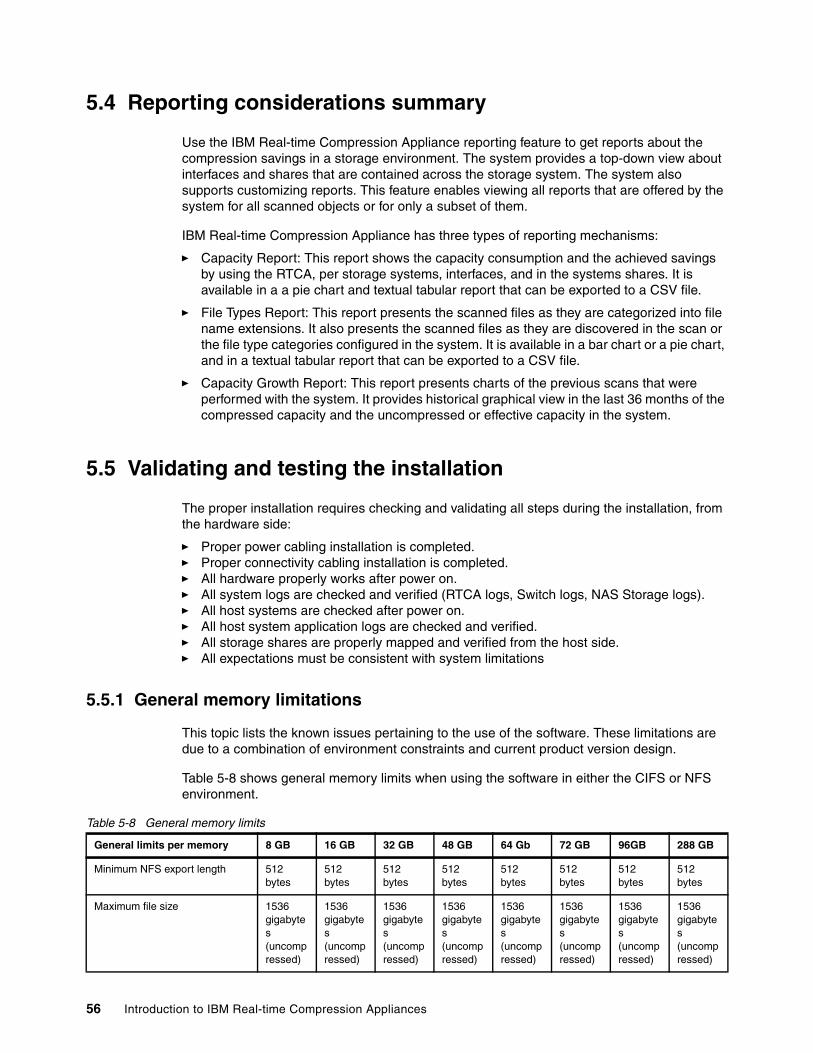
5.4 Reporting considerations summary
Use the IBM Real-time Compression Appliance reporting feature to get reports about the compression savings in a storage environment. The system provides a top-down view about interfaces and shares that are contained across the storage system. The system also supports customizing reports. This feature enables viewing all reports that are offered by the system for all scanned objects or for only a subset of them.
IBM Real-time Compression Appliance has three types of reporting mechanisms:
� Capacity Report: This report shows the capacity consumption and the achieved savings by using the RTCA, per storage systems, interfaces, and in the systems shares. It is available in a a pie chart and textual tabular report that can be exported to a CSV file.
� File Types Report: This report presents the scanned files as they are categorized into file name extensions. It also presents the scanned files as they are discovered in the scan or the file type categories configured in the system. It is available in a bar chart or a pie chart, and in a textual tabular report that can be exported to a CSV file.
� Capacity Growth Report: This report presents charts of the previous scans that were performed with the system. It provides historical graphical view in the last 36 months of the compressed capacity and the uncompressed or effective capacity in the system.
5.5 Validating and testing the installation
The proper installation requires checking and validating all steps during the installation, from the hardware side:
� Proper power cabling installation is completed.� Proper connectivity cabling installation is completed.� All hardware properly works after power on.� All system logs are checked and verified (RTCA logs, Switch logs, NAS Storage logs).� All host systems are checked after power on.� All host system application logs are checked and verified.� All storage shares are properly mapped and verified from the host side.� All expectations must be consistent with system limitations
5.5.1 General memory limitations
This topic lists the known issues pertaining to the use of the software. These limitations are due to a combination of environment constraints and current product version design.
Table 5-8 shows general memory limits when using the software in either the CIFS or NFS environment.
Table 5-8 General memory limits
General limits per memory 8 GB 16 GB 32 GB 48 GB 64 Gb 72 GB 96GB 288 GB
Minimum NFS export length 512 bytes
512 bytes
512 bytes
512 bytes
512 bytes
512 bytes
512 bytes
512 bytes
Maximum file size 1536 gigabytes (uncompressed)
1536 gigabytes (uncompressed)
1536 gigabytes (uncompressed)
1536 gigabytes (uncompressed)
1536 gigabytes (uncompressed)
1536 gigabytes (uncompressed)
1536 gigabytes (uncompressed)
1536 gigabytes (uncompressed)
56 Introduction to IBM Real-time Compression Appliances
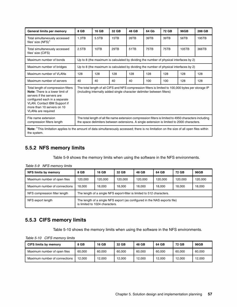
5.5.2 NFS memory limits
Table 5-9 shows the memory limits when using the software in the NFS environments.
Table 5-9 NFS memory limits
5.5.3 CIFS memory limits
Table 5-10 shows the memory limits when using the software in the NFS environments.
Table 5-10 CIFS memory limits
Total simultaneously accessed files' size (NFS)1
1.3TB 5.5TB 15TB 26TB 39TB 39TB 56TB 195TB
Total simultaneously accessed files' size (CIFS)
2.5TB 10TB 29TB 51TB 75TB 75TB 105TB 366TB
Maximum number of bonds Up to 8 (the maximum is calculated by dividing the number of physical interfaces by 2)
Maximum number of bridges Up to 8 (the maximum is calculated by dividing the number of physical interfaces by 2)
Maximum number of VLANs 128 128 128 128 128 128 128 128
Maximum number of servers 40 40 40 40 100 100 128 128
Total length of compression filtersNote: There is a lower limit of servers if the servers are configured each in a separate VLAN. Contact IBM Support if more than 10 servers on 10 VLANs are required
The total length of all CIFS and NFS compression filters is limited to 100,000 bytes per storage IP (including internally added single character delimiter between filters)
File name extension compression filters length
The total length of all file name extension compression filters is limited to 4950 characters including the space delimiters between extensions. A single extension is limited to 2000 characters.
Note: 1This limitation applies to the amount of data simultaneously accessed; there is no limitation on the size of all open files within the system.
General limits per memory 8 GB 16 GB 32 GB 48 GB 64 Gb 72 GB 96GB 288 GB
NFS limits by memory 8 GB 16 GB 32 GB 48 GB 64 GB 72 GB 96GB
Maximum number of open files 120,000 120,000 120,000 120,000 120,000 120,000 120,000
Maximum number of connections 18,000 18,000 18,000 18,000 18,000 18,000 18,000
NFS compression filter length The length of a single NFS export-filter is limited to 512 characters.
NFS export length The length of a single NFS export (as configured in the NAS exports file)is limited to 1024 characters.
CIFS limits by memory 8 GB 16 GB 32 GB 48 GB 64 GB 72 GB 96GB
Maximum number of open files 60,000 60,000 60,000 60,000 60,000 60,000 60,000
Maximum number of connections 12,000 12,000 12,000 12,000 12,000 12,000 12,000
Chapter 5. Solution design and implementation planning 57

58 Introduction to IBM Real-time Compression Appliances
Chapter 6. Performance considerations
In this chapter, we discuss several factors that must be considered when you design an optimal configuration with the IBM Real-time Compression Appliance (RTCA).
A key benefit of the RTCA solution is being able to perform compression while maintaining high performance. The compression appliance is part of the overall storage solution, and as such, it must be reviewed together with the storage system itself. Various performance requirements must be part of this review.
6
© Copyright IBM Corp. 2013. All rights reserved. 59

6.1 Performance requirements
The focus areas for performance are throughput, response time, and scalability:
� Throughput: The storage solution is typically measured by the number of megabytes per second of data being read or written to it. We can measure this throughput during work hours and also peak time, to make sure the system is designed to provide expected service levels, even in high load time windows.
� Response time: Users are sensitive to how responsive the system is to the actions and jobs that they perform in the computing systems. The user response time is affected by many components: user actions themselves, client-side application processing time, operating systems, networking layers, physical links, file system processing, and the disk sub-system.
� Scalability: Any computer system is typically designed to handle current and future load levels. Planning ahead requires a detailed review of the performance metrics of an overall storage solution.
One of the major objectives of RTCA v4.1 is to improve the throughput. While significant performance boost is gained by the new IBM System x3650 M4 hardware platform, which supports the Xeon E-2600 CPU, there are also software changes that are targeted to improve the performance.
Release v4.1 also delivers higher performance compared to previous releases. The newly introduced hardware is suitable to handle higher performance loads and has an improved and optimized software operating system.
Next we review processes for configuring the highest performance Real-time Compression Appliances solutions.
6.2 Performance suggestions
There are various configuration items and parameters that affect the performance of a Network Attached Storage (NAS) setup that includes the IBM Real-time Compression Appliance solutions.
6.2.1 Read-cache allocation
There are two different types of profile support for the new STN7800. The first one is Performance profile, which is the default, and the other is Capacity profile. A specific amount of the compression appliance memory is allocated for read cache purposes. The default allocation in V4.1 is 47 gigabytes, which typically provides very high cache hit ratios. However, in some cases, it will be necessary to change the read cache to provide the desired results.
60 Introduction to IBM Real-time Compression Appliances

Table 6-1 lists the read cache size for the STN7800 model.
Table 6-1 Read cache size
Memory tuning: The Real Time Compression Appliance version 4 release 1 is provided with a default read-cache memory allocation that favors read-cache, while at the same time limiting the total size of compressed data that can be opened.
The default setting for the STN7800 provides compressed data as follows:
� 6.5 TB of concurrent compressed data when written in 8 KB average I/O size (NFS/CIFS)
� 26 TB of concurrent compressed data when written in 32 KB average I/O size (NFS)
� 48.7 TB of concurrent compressed data when written in 60 KB average I/O size (CIFS)
The highest concurrent capacity setting for the STN7800 (option General:MemoryProfileMode 1) provides compressed data as follows:
� 14 TB of concurrent compressed data when written in 8 KB average I/O size (NFS/CIFS)
� 56 TB of concurrent compressed data when written in 32 KB average I/O size (NFS)
� 105 TB of concurrent compressed data when written in 60 KB average I/O size (CIFS)
The default setting for the STN6800 and STN6500 provides compressed data as follows:
� 4.8 TB of concurrent compressed data when written in 8 KB average I/O size (NFS/CIFS)
� 19.2 TB of concurrent compressed data when written in 32 KB average I/O size (NFS)
� 36.6 TB of concurrent compressed data when written in 60 KB average I/O size (CIFS)
The highest concurrent capacity setting for the STN6800 and STN6500 (option General:MemoryProfileMode 1) provides compressed data as follows:
� 11 TB of concurrent compressed data when written in 8 KB average I/O size (NFS/CIFS)
� 44 TB of concurrent compressed data when written in 32 KB average I/O size (NFS)
� 83.8 TB of concurrent compressed data when written in 60 KB average I/O size (CIFS)
The highest concurrent capacity setting can be accomplished if we switch to an allocation option General:MemoryProfileMode 1 mode as shown in Example 6-1. An engine warm restart is required to apply the settings.
Cache capacity Performance profile Capacity profile
96 GB Read cache 47 GB 15 GB
Engine memory 40 GB 74 GB
288 GB Read cache 100 GB 15 GB
Engine memory 175 GB 260 GB
Explanation: The data sizes are measured in the uncompressed size of the files. In a CIFS-only environment, in the typical I/O pattern of maximum I/O size of 60KB, users can access concurrently up to 48.7 TB of data through an STN7800. The NAS system can have more data than this number; the measurement is for data that is opened at the same time.
Chapter 6. Performance considerations 61

Example 6-1 Option General:MemoryProfileMode 1
option General:MemoryProfileMode 1 engine restart warm
6.2.2 Parallelism of I/O
The Real-time Compression Appliance software is tuned for a multi-core processor architecture and is highly efficient in handling concurrent compression and decompression tasks. However, single threaded I/O does not fully utilize this capability. For this reason, any application configuration changes that increase the concurrency of I/O operations will increase the overall performance and reduce the overall load of the appliance.
6.2.3 Interval between files
This feature can be set from RTCA GUI. It defines how many milliseconds to wait before a new file is processed by the RTCA engine, and describes how to improve the Compression Accelerator performance.
Use the following procedure to change the interval between files:
1. Click Storage, as shown in Figure 6-1, and select the correct storage name. We selected the N3300A option.
Figure 6-1 “Storage” configuration panel
2. For the N3300A selection, which shows what kind of files are compressed and which mode is selected (transparent or compressed), click Compression accelerator, as shown in Figure 6-2.
62 Introduction to IBM Real-time Compression Appliances

Figure 6-2 “Compression Accelerator” option
3. Change the Interval between files (millisecond) value to 1 (Figure 6-3) to get the highest performance.
Figure 6-3 “Interval between files (millisecond)” option
Chapter 6. Performance considerations 63

6.2.4 Compression ratio
A useful principle is that the higher the compression ratio, the lower the CPU time that is spent on compressing the data. The same rule applies for decompression also. Therefore, a preferable approach is to configure file types with low expected compression ratio in the File Extensions to Exclude field on the Storage page. This approach reduces CPU time that is spent attempting to compress files with low expected file size reduction.
Use the following procedure to create a list of file extensions to exclude:
1. Click Storage, and select File extensions to exclude, as shown in Figure 6-4.
Figure 6-4 “File extensions to exclude” option
2. Specify the list of file extensions to exclude, as shown in Figure 6-5. For example, specify the following extensions:
zip gz tgz arj xlm
Figure 6-5 List of file extensions to exclude
64 Introduction to IBM Real-time Compression Appliances
Click Apply to make the changes to file extensions.
6.2.5 Transparent versus compressed traffic
A basic concept of the compression appliance is that it adds minimal latency when traffic arrives to it and gets processed by its network interfaces. However, it reduces the latency of I/O requests sent to the storage, because less data is sent to the storage compared with the original data sent by the client.
However, suppose that the appliance is implemented without compressing data, or when only a minimal amount of data is compressed. In this case, the latency added by the appliance, being an additional network hop, will not be compensated, and the overall throughput will be lowered. It is best to implement the appliance and start compressing files right away.
Important: Changing file extension filters might cause client session disconnections on this appliance and affect partner appliances (in a high-availability configuration).
Chapter 6. Performance considerations 65

66 Introduction to IBM Real-time Compression Appliances
Chapter 7. Interaction with native NAS, host OS, and application features
In this chapter, we provide a description of how the IBM RTCA product interacts with the native features of the underlying NAS storage controller.
The features and interactions described include these:
� NAS deduplication� NAS compression� Thin provisioning� Snapshot copies� Volume cloning� NAS backup� NAS replication� Backup to external media� Protocol support
7
© Copyright IBM Corp. 2013. All rights reserved. 67
7.1 Interaction with native N series features
By design, the RTCA is transparent to the underlying NAS storage controller. It compresses the client data prior to writing to the NAS, and uncompresses the client data as it is read by the client.
Therefore, most advanced native NAS features, such as snapshot backup, deduplication, or replication, are supported and work with the compressed form of the client data. The notable exception is the native NAS compression feature, because the RTCA product is designed to replace the need for this feature.
However, it is important to understand how the RTCA product interacts with certain NAS features, and how this might differ from the native NAS storage efficiency features.
7.1.1 NAS system resources and limitations
This section discusses NAS system resources and limitations.
Processor load on the NAS storage controllerBy compressing the client data before it is written, the RTCA product effectively reduces the workload on the underlying NAS storage controller.
Relative to native NAS compression, the RTCA also relives the NAS storage controller’s processor from having to perform the data compression. The RTCA is effectively functioning as a compression off-load engine.
This can be a significant advantage in environments where the NAS processor is the performance bottleneck. It can improve both the NAS client performance and other functions such as NAS cluster failover and failback times.
Maximum volume or aggregate size limitationsBy compressing the client data before it is written to the NAS storage controller, the RTCA effectively increases the storage capacity of the underlying NAS volume.
For example, when running DOT 7.x, the IBM N series storage controllers have a maximum aggregate size of 16 TB. This also limits the maximum volume size to the same capacity, though for operational reasons it might be significantly smaller. DOT 8.x introduced 64 bit aggregates with increased aggregate limits based on individual controller performance. Currently, the maximum aggregate size for N series systems is 162 TB.
If the RTCA product is able to achieve a 5:1 compression ratio (for example, with Oracle data), then the effective volume or aggregate size is increased by the same ratio. In this example, a 16 TB volume can store up to 80 TB of data.
Important: Unless otherwise stated, all NAS features described in this section are for the IBM N series storage platform. Other NAS platforms might have comparable features, but their interaction with the RTCA product must be confirmed prior to implementation.
Attention: During normal operations, the RTCA performs in-line compression and decompression of the client data stored in the NAS volumes. However, sometimes it might be necessary to use the Data Recovery Utility to manually decompress the client data. In this case, there needs to be sufficient available capacity to store the decompressed data.
68 Introduction to IBM Real-time Compression Appliances
NAS file system block alignmentFor workloads that perform block-level I/O on file-based virtual LUNs (such as VMware with client partitions in VMDK files), it is best practice to align the application’s file system block boundaries with the underlying NAS file system block boundaries. If this is not done, then a single application I/O can spawn multiple I/Os on the NAS file system, causing unnecessary processing and impacting performance.
For more information about NAS storage block alignment, see the following technical report:
ftp://public.dhe.ibm.com/storage/isv/NS3593-0.pdf
However, the RTCA product compresses the original client data, changing its block structure and significantly reducing the workload on the underlying NAS storage controller. So it is not necessary (or possible) to align the application and NAS file system block boundaries.
Restrictions due to other NAS featuresIn some cases, the native NAS features might impose other restrictions or incompatibilities on the underlying NAS platform.
For example, with the IBM N series storage controller’s native features:
� The recommended volume count is lower when using the NAS deduplication feature.� Synchronous replication is not supported when using the native NAS compression
feature.
By off-loading the data compression task to the RTCA product, these restrictions can be avoided, while still providing significant capacity savings.
7.1.2 Thin provisioning
The NAS thin provisioning feature is unaffected by the RTCA product.
7.1.3 NAS deduplication
The RTCA product is designed to complement the native NAS deduplication feature.
OverviewAlthough the traditional view is that data compression is incompatible with deduplication, RTCA’s Random Access Compression Engine enables these two storage efficiency features to work together.
If the data is already compressed by the RTCA product, then enabling the NAS deduplication feature can result in further significant reduction in storage capacity, and a reduction in the deduplication processing time.
For a good description using RTCA compression with native NAS deduplication, see the document at the following website:
� http://public.dhe.ibm.com/common/ssi/ecm/en/tsw03086usen/TSW03086USEN.PDF
If the data is already deduplicated with the native NAS feature, then enabling the RTCA product will require additional temporary storage capacity. This is because the act of compressing the data will break the deduplicated block relationships. Also, if any snapshot copies exist, then the capacity cannot be released until the snapshots are deleted. After the data has been compressed by the RTCA product, then subsequent NAS deduplication will result in a further reduction in storage capacity.
Chapter 7. Interaction with native NAS, host OS, and application features 69

Maximum deduplication volume size limitationsThe maximum volume size that can support NAS deduplication varies with the NAS controller’s hardware model and software OS level.
At the time of writing this book, the largest volume size that supported deduplication was 16 TB. When combined with the maximum shared data limit (again, 16 TB), it means that no NAS volume can hold more than 32 TB of logical data, even with NAS deduplication.
For a description of these limits, see the following website:
� https://kb.netapp.com/support/index?page=content&id=3010088
However, because the RTCA product compresses the data before it is written to the NAS volume, these limits are effectively multiplied by the compression ratio.
Consider these examples:
� Assuming a 5:1 compression ratio by the RTCA product:
– A 16 TB volume can contain up to 80 TB of compressed data
� Assuming a 2:1 deduplication ratio by the NAS controller:
– A 16 TB volume can contain up to 32 TB of logical data
– Which matches the maximum shared data limit)
– Which is up to 160 TB of logical (compressed + deduplicated) data
Obviously, the actual capacity will vary depending on your specific data set. The foregoing examples are intended to be indicative only.
7.1.4 NAS compression
The RTCA product is designed to replace the need for native NAS compression.
If the data is already compressed by the RTCA product, do not enable the native NAS compression feature. The double compression of the data might reduce performance and also increase the storage capacity required.
If the data is already compressed with the native NAS feature, then that feature must be disabled and the RTCA product must be enabled to compress new data. If desired, the RTCA Compression Accelerator can be enabled to recompress the existing data (removing the decompression overhead from the underlying NAS device).
See Example 7-1 for a description of how to disable the native NAS compression. for a specific data volume.
Example 7-1 How to disable native NAS compression
NAS> vol status /vol/test_vol1 Volume State Status Options test_vol1 online raid_dp, flex compression=on
Containing aggregate: 'aggr0'
NAS> vol options /vol/test_vol1 compression off
70 Introduction to IBM Real-time Compression Appliances

NAS> vol status /vol/test_vol1 Volume State Status Options test_vol1 online raid_dp, flex
Containing aggregate: 'aggr0'
NAS> df -S /vol/test_vol1Filesystem used compressed a-sis %saved/vol/test_vol1/ 28272 16880 0 37%
Any data that had been compressed by the native NAS compression will still be available after the feature has been disabled.
7.1.5 Snapshot copies
The NAS snapshot feature is unaffected by the RTCA product, except as detailed next.
Existing snapshot copiesWhen an existing data volume contains snapshot backups, any updates will consume additional capacity until the snapshots are deleted to free the locked blocks. This is standard behavior for NAS snapshot technology.
When the RTCA is configured to compress new data, then this temporary increase in capacity will be lower than otherwise, because only the additional capacity of the data’s compressed form needs to be stored. Note, however, that the spare required for the file’s original uncompressed form will not be released until the snapshot is deleted.
Compression AcceleratorIf the RTCA’s Compression Accelerator feature is activated (so as to compress all existing data), then this might generate a very large delta relative to the snapshot backups, and might require significant free capacity to complete successfully.
If possible, consider deleting any snapshot backups prior to activating the Compression Accelerator.
7.1.6 SnapRestore
The RTCA product is designed to support advanced NAS data recovery solutions such as the IBM N series SnapRestore command. This feature can rapidly restore an entire volume, or a single file, without any communication with the RTCA product.
OverviewIn this case, the RTCA product might already have a compressed file opened with information about its metadata and structure stored in the RTCA memory of the RTCA. However, now that the file is replaced, this information is stale. To handle this situation gracefully, a feature has been introduced in the compression engine called FileSwap.
The FileSwap feature automatically detects changes in the mtime (modify time) of files as they are being accessed and uses this information to identify cases where the file has been replaced using an external mechanism such as SnapRestore.
When FileSwap identifies a potential file replacement, an message is sent to the requesting client to instruct it to retry the file operation, and the RTCA will open the updated file instead.
Chapter 7. Interaction with native NAS, host OS, and application features 71
Compression AcceleratorNative NAS restore operations such as IBM N series SnapRestore conflict with the Compression Accelerator feature. Do not perform NAS restore operations while Compression Accelerator is running.
7.1.7 FlexClone
The NAS FlexClone feature is unaffected by the RTCA product.
A volume FlexClone will create a new volume that is linked to a snapshot copy of the original volume. The new volume will contain a view of the RTCA compressed data. Access to copied, mirrored, or cloned volumes is compressed and a new export or share needs to be created, in compressed mode, to allow client access to this volume.
A file-level FlexClone will create a new file that is linked to the same blocks as the original file in the same volume. The new file will contain a view of the RTCA compressed data. The cloned file is immediately available through the RTCA compressed interface.
A common use case for file-level FlexClones is with the N series Virtual Storage Console (VSC) VMWare vCenter plug-in.
7.1.8 SnapVault backup
The NAS SnapVault feature is unaffected by the RTCA product.
Because the RTCA product compresses the client data before writing to the source NAS storage controller, the SnapVault feature will read, send, and store the data in compressed form. This saves processing overhead on the NAS controllers, and reduces traffic on the backup network.
In contrast, because SnapVault occurs at the logical (file system) level, any NAS deduplicated or NAS compressed data will need to be uncompressed in memory on the source NAS controller before being sent across the network in uncompressed form. It will then be necessary to re-deduplicate, or re-compress the data on the target system. This overhead is unnecessary with the RTCA product.
7.1.9 SnapMirror replication
The NAS SnapMirror feature is unaffected by the RTCA product, except as detailed next.
Volume SnapMirrorBecause the Volume SnapMirror feature operates at the physical block level, it will read, send, and store the data in compressed format. This saves processing overhead on the source and target NAS controllers, and reduces traffic on the replication network.
Tip: When a volume is copied (for example, using N series “vol copy”), mirrored (using N series SnapMirror or EMC SRDF) or cloned (for example, using N series “vol clone”), the NFS file handle is replicated too. Any NFS compression filters configured for the source volume apply to the destination volume too.
72 Introduction to IBM Real-time Compression Appliances

Qtree SnapMirrorBecause the RTCA product compresses the client data before writing to the source NAS storage controller, the QTree SnapMirror feature will read, send, and store the data in compressed form. This saves processing overhead on the NAS controllers, and reduces traffic on the replication network.
In contrast, because QTree replication occurs at the logical (file system) level, any NAS deduplicated or NAS compressed data will need to be uncompressed in memory on the source NAS controller before being sent across the network in uncompressed form. It will then be necessary to re-deduplicate, or re-compress the data on the target system. This overhead is unnecessary with the RTCA product.
Replication modesData that has been compressed with the RTCA product can be replicated in any of the three SnapMirror modes:
� Synchronous mode� Semi-synchronous mode� Asynchronous mode
In contrast, any NAS deduplicated data on the IBM N series storage controller cannot be replicated in synchronous mode.
SnapMirror compressionRecent versions of Data ONTAP have introduced the ability to compress the replication data stream on the source NAS controller, then transfer the compressed data, and uncompress the data on the target NAS controller.
This overhead is unnecessary with the RTCA product, because all SnapMirror modes read, send, and store the compressed form of the data.
7.1.10 MetroCluster configuration
The NAS MetroCluster configuration is supported by the RTCA product. This will require at least one RTCA device at each site.
7.1.11 Volume copy
The NAS Volume copy feature is unaffected by the RTCA product. The data is copied to the new volume in compressed form.
7.1.12 NDMP copy
The N series NDMP copy feature is unaffected by the RTCA product. The data is copied to the new volume in compressed form.
In contrast, because NDMP occurs at the logical (file system) level, any NAS deduplicated or NAS compressed data will need to be uncompressed in memory on the NAS controller before being sent across the network and stored on the target in uncompressed form.
Chapter 7. Interaction with native NAS, host OS, and application features 73

7.1.13 Access by other file protocols
The RTCA product only provides transparent compression and decompression of data by the NAS protocols only (NFS and CIFS). The data is stored on the underlying NAS storage controller in compressed form.
If other file protocols are enabled, such as HTTP or FTP, then the data will only be accessible in compressed form, and will not be transparently decompressed by the RTCA product. This effectively makes the data unusable by these non-NAS protocols.
In contrast, the native NAS deduplication and NAS compression features do support access by the non-NAS protocols.
Of course, it is usually preferable to connect a third-party HTTP server by the NAS protocols and access the RTCA compressed data.
7.2 Interaction with native host OS features
By design, the RTCA product is transparent to the NAS clients. It compresses the client data prior to writing to the NAS, and uncompresses the client data after reading from the NAS.
7.2.1 Host protocol support
The RTCA product supports transparent data compression by the following NAS protocols.
Common Internet File SystemThe RTCA product is fully compatible with clients that conform to the Common Internet File System (CIFS) access protocol, which also known as Server Message Block (SMB).
Network File SystemThe compression appliance is fully compatible with clients that conform to the NFSv3 protocol standards. NFSv3 is supported over TCP and UDP.
Tip: The RTCA product is transparent to block-mode access by iSCSI. The iSCSI traffic is not compressed.
Reference: Support for the SMB2 protocol was introduced from Version 3.8 of the RTCA product.
Support: The NFSv2 and NFSv4 protocols are partially supported, with all access passing through the compression appliance transparently. They can be used to access data on the underlying NAS storage controller, but they are unable to correctly read any data that has been compressed by the RTCA product.
74 Introduction to IBM Real-time Compression Appliances

Mixed access modeThe RTCA product supports simultaneous client access to the same data volumes using both CIFS and NFS protocols.
7.2.2 Host integration agents
Any N series integration agents on the host (such as SnapDrive) are unaffected by the RTCA product.
The RTCA product does not itself require any software agents on the host.
7.2.3 Virtual block devices over NFS
Several VM hypervisors support storing the guest virtual machine images on an NFS storage pool. Example of this include VMWare, Solaris Zones, IBM PowerVM®, and Linux KVM.
The RTCA product is transparent to both the VM hypervisor and the guest VMs. However, it is important to consider how the RTCA might interact with the features on the guest VM’s file system.
For example, if the guest VM’s file system supports compression, deduplication, or encryption features, these will probably prevent any further data compression by the RTCA.
7.3 Interaction with native application features
By design, the RTCA is transparent to the applications on the host. It compresses the application data prior to writing to the NAS, and uncompresses the application data after reading from the NAS.
7.3.1 Application data compression
Some applications have the ability to work with natively compressed data files. Examples of this include Oracle compression and Microsoft SQL Server compression.
For more information about these two examples, see the following websites:
� http://www.oracle.com/us/products/database/options/advanced-compression/� http://msdn.microsoft.com/en-us/library/dd894051%28v=sql.100%29.aspx
The RTCA product will be unable to provide additional compression if the application is configured to compress its own data files. In fact, attempting to compress the already compressed data files might increase the storage capacity required.
In this case, the RTCA must be configured for transparent mode on the shares that contain application compressed data.
Support: The underlying NAS storage controller also needs to support, and be correctly configured for, multi-protocol file access.
Chapter 7. Interaction with native NAS, host OS, and application features 75
7.3.2 Applications with native compressed file formats
Some applications have natively compressed data files. Examples of this include Microsoft Office OOXML format files, and most video and graphics formats.
For more information some common examples, see the following websites:
� http://msdn.microsoft.com/en-us/library/aa338205%28v=office.12%29.aspx� http://en.wikipedia.org/wiki/List_of_archive_formats� http://en.wikipedia.org/wiki/Graphics_file_format
The RTCA product will be unable to provide additional compression if the application is configured to compress its own data files. In fact, attempting to compress the already compressed data files might increase the storage capacity required.
In this case, the RTCA must be configured to exclude the compressed data file types.
7.3.3 Application integration agents
Any NAS integration agents specific to the application (such as SnapManager) are unaffected by the RTCA product.
The RTCA product does not itself require any software agents for application integration.
76 Introduction to IBM Real-time Compression Appliances
Chapter 8. Deploying Real-time Compression Appliances
In this chapter, we provide a description of the first installation steps that are needed in order to configure the Real-time Compression Appliance (RTCA) product.
8
© Copyright IBM Corp. 2013. All rights reserved. 77

8.1 Physical installation of Real-time Compression Appliance
The first step is to install the IBM Real-time Compression Appliance (RTCA) in the rack. Follow the instructions in the Rack Installation Instructions for IBM Gen-II Slides Kit, 69Y4034 document. You can find it on the IBM Real-time Compression Appliances Documentation CD or on the IBM support website:
http://www.ibm.com/support
8.2 Cabling the RTCA product for configuration
The second step after mounting the device in the rack is to connect the minimum cabling needed in order to perform the basic installation steps.
At this stage it is not necessary to connect the RTCA product within the data paths. You can do it later after the initial installation setup in order to provide non-disruptive implementation.
8.3 Connecting to the RTCA product
The RTCA product can be managed using two kinds of connections:
� Direct connection: Standard KVM or using serial console connection by RS232 serial protocol as shown in Figure 8-1.
Figure 8-1 Direct management connection
Important: Connect the RTCA product to an appropriate power source. For higher redundancy, connect both power supplies to different main electricity lines, while at least one power supply for the engine must be connected through an un-interruptible power supply.
Precaution: This product is not intended to be connected directly or indirectly by any means whatsoever to interfaces of public telecommunications networks.
78 Introduction to IBM Real-time Compression Appliances

� Remote connection: Web GUI management or SSH CLI. In this case, you will have to configure the remote access protocol by setting up an IP address at the Real-time Compression Appliance as shown in Figure 8-2.
Figure 8-2 Remote management connection
Using the KVM, RS232, and SSH, you will be able to perform CLI management at the Real-time Compression Appliance.
8.3.1 Direct connection
The direct connection can be made by using a standard VGA monitor and a USB keyboard or by RS232. Table 8-1 presents the required information for connecting using console or serial interface.
Table 8-1 Connect a communication device
Communication device How to connect
VGA monitor and keyboard 1. Connect the VGA monitor to any of the VGA ports on the compression appliance.
2. Connect the USB keyboard to any of the USB ports on the compression appliance.
Standard RS-232 serial console 1. Connect the serial port cable to the 9-pin console port on the compression appliance.
2. Connect the other side to a terminal server, or to a PC or server with serial console port.
3. Configure the terminal emulation software to the following settings:– Bits per second: 38400– Data bits: 8– Parity: None– Stop bits: 1– Flow control: None
Connection: Use the following default credentials to connect to the RTCA system:
User name: userPassword: a1b2c3
Chapter 8. Deploying Real-time Compression Appliances 79
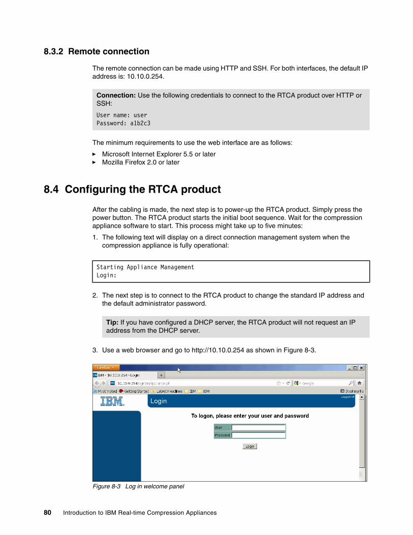
8.3.2 Remote connection
The remote connection can be made using HTTP and SSH. For both interfaces, the default IP address is: 10.10.0.254.
The minimum requirements to use the web interface are as follows:
� Microsoft Internet Explorer 5.5 or later� Mozilla Firefox 2.0 or later
8.4 Configuring the RTCA product
After the cabling is made, the next step is to power-up the RTCA product. Simply press the power button. The RTCA product starts the initial boot sequence. Wait for the compression appliance software to start. This process might take up to five minutes:
1. The following text will display on a direct connection management system when the compression appliance is fully operational:
2. The next step is to connect to the RTCA product to change the standard IP address and the default administrator password.
3. Use a web browser and go to http://10.10.0.254 as shown in Figure 8-3.
Figure 8-3 Log in welcome panel
Connection: Use the following credentials to connect to the RTCA product over HTTP or SSH:
User name: userPassword: a1b2c3
Starting Appliance ManagementLogin:
Tip: If you have configured a DHCP server, the RTCA product will not request an IP address from the DHCP server.
80 Introduction to IBM Real-time Compression Appliances

After logging in, the following interface displays as depicted in Figure 8-4. This view shows the general status of your system, and you are able to perform different tasks.
Figure 8-4 First view after login to the RTCA product
4. From the left panel, select Management Port (see Figure 8-5). Enter the desired IP address, subnet mask, and gateway. If necessary, you can change the default MTU or the Link Mode. In the last field, named Hostname, you will have to enter the designated name for this host. After finishing the settings, click the Accept button.
Figure 8-5 Setting the management interface
IP address: After changing the IP address, the following message will display asking you to log on again on the new IP address: The Management Port IP has changed.
Wait up to 30 seconds before trying to connect on the new IP address.
Chapter 8. Deploying Real-time Compression Appliances 81

5. If you are using a Direct Connection or over SSH, change the IP address using the ifconfig command (see Example 8-1).
Example 8-1 Changing the management settings
[email protected]> ifconfig mgmt -i 9.155.66.157 -s 255.255.255.0 -gw 9.155.66.1 -m 1500 -f auto
In previous versions, only one command was available to configure IPv4 and IPv6 networking environments. Previously, users had to use the -6 options to configure IPv6 networking.
Now, two commands are available to configure the environments:
– ifconfig mgmt– ifconfig6
Every command must be used with its own parameter set. Example 8-2 shows a sample usage of the ifconfig6 command.
Example 8-2 The ifconfig6 command
ifconfig6 mgmt -type auto [email protected]> ifconfig6 mgmt -type static -i 2001:bf8:2000:5180:e61f:13ff:fe6d:2348/64 -gw 2001:bf8:2000:5180::4
6. After the command was executed successfully, log on again on the new IP address. In order to check if the new configuration was made correctly, submit the ifconfig mgmt command (see Example 8-3).
Example 8-3 Verifying the current configuration of the management interface
[email protected]> ifconfig mgmtManagement PortIP: 9.155.66.157Subnet: 255.255.255.0Gateway: 9.155.66.1MTU: 1500Link mode: autoActual link mode: 100baseT/Half
82 Introduction to IBM Real-time Compression Appliances

7. Next, change the administrator password. From the web interface, choose the Security option. From the newly configured state (see Figure 8-6), change the administration password and also secure the web management interface by imposing only one IP that will be served. The password must be between 6 and 8 characters.
Figure 8-6 Changing the admin password
a. You can do the same task from the CLI using the passwd command (Example 8-4). The passwd command will change the password only for the default user: ‘user’. You have to enter the password twice. After successfully changing the password, the following message is displayed: “User password changed successfully”.
Example 8-4 Changing the default management password - part 1
[email protected]> passwdNOTE: This will change the login password for username 'user'Enter password:Enter password:User password changed successfully
b. You can also change the passwd command using the following syntax: passwd a1b2c3 (Example 8-5). In this situation, the password will be changed instantly without any other confirmation.
Example 8-5 Changing the default management password - part 2
[email protected]> passwd a1b2c3User password changed successfully
Chapter 8. Deploying Real-time Compression Appliances 83

8.5 Configuring bonds and bridges
After configuring the management interface and the administrator password, the next step is to configure bonds and bridges.
To configure first bonds and bridges, proceed as follows:
1. On the navigation menu (left panel) under Configuration, select the Network option. In the Network pane (Figure 8-7), you can see the current configuration of your compression engine, showing the following information:
– Interface cards assignment– Created bonds and bridges– Compression engine status
2. From the network panel, on Unassigned interfaces, select [Add new bond]. To create a new bond, on Bridges select [Add new bridges] to create new bridges. At the bottom of the page, select to start, stop, or restart the compression engine.
Figure 8-7 Network panel overview
8.5.1 Creating bonds
If your implementation design includes some adapter bonding between different interfaces, first you have to replicate the bonds defined in your storage at the appliance level. Because the appliance is acting as an “intelligent cable” by using adapter bonding topology, you will not be able to achieve higher failover support than the standard storage configuration. This procedure is required to achieve the goals of high-availability or failure recovery.
Tip: The compression engine cannot be started if there are no bridges and no storage interface defined. In Figure 8-7, the status of the compression engine is: Halted.
Tip: The bonds and bridges can be defined without moving the storage traffic through the storage engine or without cabling the compression appliance. Good planning can save a lot of time during the implementation and can assure a proper implementation without downtime.
84 Introduction to IBM Real-time Compression Appliances
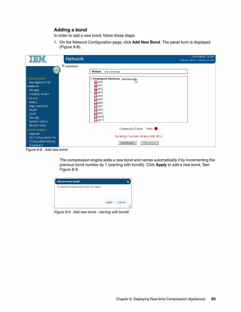
Adding a bondIn order to add a new bond, follow these steps:
1. On the Network Configuration page, click Add New Bond. The panel form is displayed (Figure 8-8).
Figure 8-8 Add new bond
The compression engine adds a new bond and names automatically it by incrementing the previous bond number by 1 (starting with bond0). Click Apply to add a new bond. See Figure 8-9.
Figure 8-9 Add new bond - starting with bond0
Chapter 8. Deploying Real-time Compression Appliances 85

2. Expand Unassigned interfaces, and click [modify] to modify the created bond for interfaces selection and bond mode. See Figure 8-10.
Figure 8-10 Modify bond
Bond modesThere are two modes of bonding physical adapters:
� EtherChannel: Use when configured to operate with EtherChannel port aggregation.
� LACP 802.3ad: Use when configured to operate with Link Aggregation Control Protocol (LACP) dynamic port aggregation.
Continue with choosing the desired bond configuration as follows; see Figure 8-11:
1. Select the required bond mode
2. Select the interfaces that are part of the new bond.
Figure 8-11 Modify bond parameters
Tip: The bond can be used for failover or for higher throughput. In order to make sense of a bond configuration, you need to configure, at the storage level and network devices, a round robin load balancing or a failover or both, between two or more physical ports.
86 Introduction to IBM Real-time Compression Appliances

3. After you finish selecting bond mode and interfaces, click Apply to bond0. Then select Unassigned interfaces to review the configured bond.
The unassigned bond is grouped together with other available interfaces in the Unassigned Interfaces selection.
Adding a bond is a procedure that you can perform using the CLI. The command used is shown in Example 8-6.
Example 8-6 Bond command structure
bond create BondInterfaceName -t [bond mode] [PhysicalInterfaceName...]
The bond command syntax is as follows:
� BondInterfaceName: Must have the following structure “bond[1 to 12]. Comparing to the GUI here, you can define bonds without incrementing the previous number starting from 0.
� bond mode: See “Bond modes” on page 86.
� PhysicalInterfaceName: Defines the interfaces that must be included in bonds separated by space.
You can use the bond command to list the current bond configuration. In Example 8-7, we create a second bond using the CLI by SSH connection.
Example 8-7 Add new bond using CLI
[email protected]> bondBond Mode Interfacesbond0 EtherChannel eth4 eth8
[email protected]> bond create bond1 -t EtherChannel eth5 [email protected]> bondBond Mode Interfacesbond0 EtherChannel eth4 eth8bond1 EtherChannel eth5 eth9
8.5.2 Creating bridges
To create a bridge using the GUI, proceed as follows:
1. From the GUI interface navigation menu, choose Network.
2. From the Network panel under Bridges click Add new bridge (see Figure 8-12).
Figure 8-12 Add new bridge
Important: A physical interface cannot belong to two different bonds at the same time.
Chapter 8. Deploying Real-time Compression Appliances 87

3. In the new bridge page (see Figure 8-13), click Apply.
Figure 8-13 Add new bridge - start with br0
The system generates a new bridge name and displays it on the Network page, under Bridges.
4. To see detailed bridge information, expand one bridge by clicking the appropriate icon left to the bridge name; or to expand all bridges, click the Expand icon. Click [Modify] to modify the created bridge (see Figure 8-14).
Figure 8-14 Modify bridge
5. In the Modify interface page (see Figure 8-15), select the physical or logical interfaces that are part of the bridge.
The IP address used for the bridge is used for discovering shares and exports from the storage system. This IP address must be in the same network as the IP address of the storage system connected to the interfaces of the specific bridge.
Tip: When using bonds, select the bonds to configure; otherwise, select the two physical ports (storage port and network port). Mixing bonds with physical interfaces is not allowed.
Important: Consider these important points when using bonds:
� A physical interface or a bond cannot be part of two bridges in the same time.
� A bridge can have only two members of logical or physical interfaces.
� Physical network interfaces are identified during the boot process, before the compression engine is active. This can affect configurations with active/passive links or bonds, such as IBM N series single VIF and EMC Fail-Safe Networking that include favoring a particular link (or bond) in case a failover of the storage systems takes place during the RTCA boot process. It is important to notice that this issue is only relevant for single links or EtherChannel bonds. LACP bonds are unaffected by this issue are therefore the best bond type.
88 Introduction to IBM Real-time Compression Appliances

The bridge IP address is also used by the auto-support, diagnostics features for shares, and exports discovery, as well as by the various network probes. Client communication to the storage system will continue to use the storage system IP address as endpoint.
At the storage level, the client IP address will be detected while discovery process occurs.
6. For using VLANs, you have to provide the following information (see Figure 8-15):
– VLAN ID: A unique number between 1 and 4094 that identifies a particular VLAN. VLAN ID 1 is typically reserved for the default VLAN.
– IP: The IP address of the bridge port. The IP address must be in the same subnet as the assigned storage server.
– Subnet: The network mask of the IP address.
– Gateway: The default gateway IP address for that bridge.
– MTU: An optional maximum transmission unit size. The default value is 1500.
7. Click Accept Changes to VLAN if you configured a VLAN and want to apply changes to the bridge name to complete the configuration. The system creates the bridge and displays a success message. Click Back to Network Configuration to display the current configuration.
Figure 8-15 Modify bridge parameters.
8. After completing the bridge configuration, you still have to configure storage interface first before starting up the Real-time Compression Engine, see Figure 8-16.
Figure 8-16 Start Engine without configuring storage interface
Important: When configuring VLAN-tagged bridges, a top-level bridge IP configuration is required. The top-level bridge can use any subnet.
Chapter 8. Deploying Real-time Compression Appliances 89

To create a bridge by using the CLI, proceed as follows:
1. Use the bridge command. The command used to create a new bridge has the structure shown in Example 8-8.
Example 8-8 Bridge command structure
bridge create BridgeIfName [-i BridgeIP -s BridgeMask [-b broadcastMask] [-gw GateWay]]
2. Define the following parameters:
– BridgeIfName - The name of the bridge you want to create. The name must contain br[number of the bridge].
– Bridge IP - The IP address used by the bridge in the network.
– BridgeMask
– GateWay
3. Add the logical or physical interfaces to the bridge, as shown in Example 8-9.
Example 8-9 Add new interfaces to the bridge
bridge addif BridgeIfName InterfaceA InterfaceB
Example 8-10 presents the complete sequence shown before by using the GUI, but done here from the CLI, using the bridge command and the engine start command.
Example 8-10 Add new bridge
[email protected]> bridgeNo bridges or vlans have been defined
[email protected]> bridge create br0 -i 192.168.0.110 -s 255.255.255.0
[email protected]> bridge
Bridge IP Netmask Broadcast Gateway MTU br0 192.168.0.110 255.255.255.0 192.168.0.255 - 1500Interfaces-
[email protected]> bridge addif br0 bond0 [email protected]> bridgeBridge IP Netmask Broadcast Gateway MTU br0 192.168.0.110 255.255.255.0 192.168.0.255 - 1500 Interfacesbond0 bond1
Important: A bridge configuration cannot be changed while the compression engine is started. In order to change a bridge configuration, you must stop the compression engine.
90 Introduction to IBM Real-time Compression Appliances
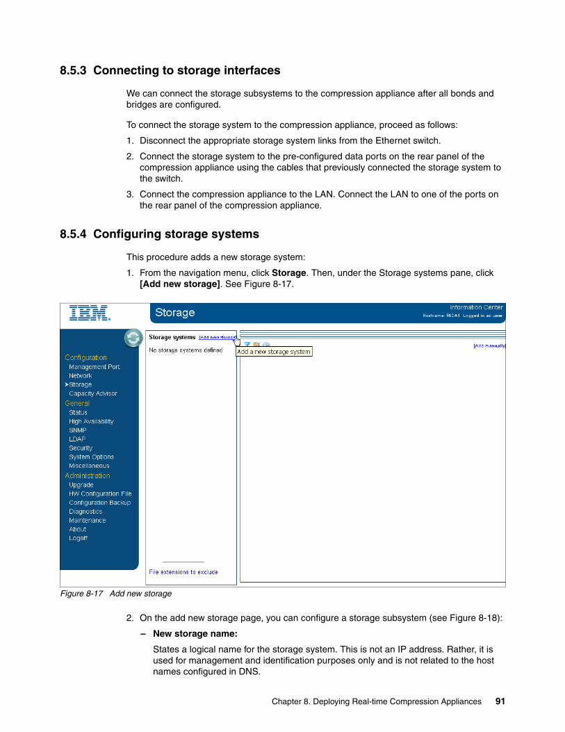
8.5.3 Connecting to storage interfaces
We can connect the storage subsystems to the compression appliance after all bonds and bridges are configured.
To connect the storage system to the compression appliance, proceed as follows:
1. Disconnect the appropriate storage system links from the Ethernet switch.
2. Connect the storage system to the pre-configured data ports on the rear panel of the compression appliance using the cables that previously connected the storage system to the switch.
3. Connect the compression appliance to the LAN. Connect the LAN to one of the ports on the rear panel of the compression appliance.
8.5.4 Configuring storage systems
This procedure adds a new storage system:
1. From the navigation menu, click Storage. Then, under the Storage systems pane, click [Add new storage]. See Figure 8-17.
Figure 8-17 Add new storage
2. On the add new storage page, you can configure a storage subsystem (see Figure 8-18):
– New storage name:
States a logical name for the storage system. This is not an IP address. Rather, it is used for management and identification purposes only and is not related to the host names configured in DNS.
Chapter 8. Deploying Real-time Compression Appliances 91
– Vendor:
Identifies the storage system vendor.
Each storage vendor manages the NFS file structure, and additional parameters such as snapshot folders and anti-virus share names, in different ways. Configure the correct storage vendor of this storage interface, so the compression appliance can provide the expected results.
– Compression mode:
Determines whether the storage medium is configured:
Compress only selected shares/exports
All traffic to the storage system IP address remains uncompressed by default. Only shares listed in the Compression Filters page will work in compressed mode. Use compress only selected shares/exports mode in instances where most of the traffic to the storage system IP address remains uncompressed.
Compress all shares/exports except selected
All traffic to the storage interface is compressed by default. Only shares listed in the Compression Filters page will work in uncompressed mode (the list of shares in the Compression Filters page acts as an exclusion list for compression), therefore configure explicitly which shares will store uncompressed data as all other shares will store compressed data. Use compress all shares/exports except selected mode in instances where most of the traffic to the storage system IP address remains compressed.
Tip: Only Netapp, EMC, and N series are supported vendors on the RTCA Version 4.1 code.
Files: In this mode, the appliance does not decompress previously compressed files. Verify that no files are compressed in the respective shares and exports prior to setting this mode. It is only possible to convert a storage interface configured as compress all shares/exports except selected mode to compress only selected shares/exports mode if the storage interface was not configured previously as compress only selected shares/exports mode. This limitation is designed to prevent an incorrect configuration.
Filters: When changing an existing storage interface setting from “Compress only selected shares/exports” to “Compress all shares/exports except selected,” an automatic conversion occurs. The compression filters will be updated to reflect the change, and the storage interface will be left with Compress New Files enabled. To resume compression, proceed as follows:
1. Verify the compression filters.2. Make all necessary changes.3. Disable Compress New Files.
92 Introduction to IBM Real-time Compression Appliances

– Compress New Files:
Sets the operation mode for new files created on a storage interface.
When Compress New Files is enabled, shares configured to work in “Compress all shares/exports except selected” mode will have existing files read and updated based on their current state (compressed or uncompressed), but new files will be created as uncompressed files. This does not change the behavior of the storage system compression mode, which pertains strictly to how new files will be created. Use the Compress New Files mode in cases where it is important to preserve the system maintenance operations and the current state of shares.
For example, suppose a storage system IP address is configured as “Compress all shares/exports except selected” in its Compression Mode field, and the storage administrator wants to create a new share that must work in uncompressed mode, so a compression filter is created after the share is created on the storage. Configure the system in Compress New Files mode before adding the share, to avoid creating compressed files on the storage; then disable Compress New Files after the share is added to the compression filters exclude list.
Table 8-2 provides the mapping between old to new terminology.
Table 8-2 New terminology
– Domain user– Domain password– Domain name
Figure 8-18 Add new storage
4. The next step is to configure storage interface. All storage system IP addresses configured on interfaces, which are connected through the IBM Real-time Compression Appliances (RTCAs), must be configured through these procedures.
New terminology Old terminology
Compress all shares/exports except selected, Compress only selected shares/exports
Compressed, Transparent
Compress New Files No New Compression
CLI unchanged: The CLI remains as before so changes are not required for scripts.
Chapter 8. Deploying Real-time Compression Appliances 93
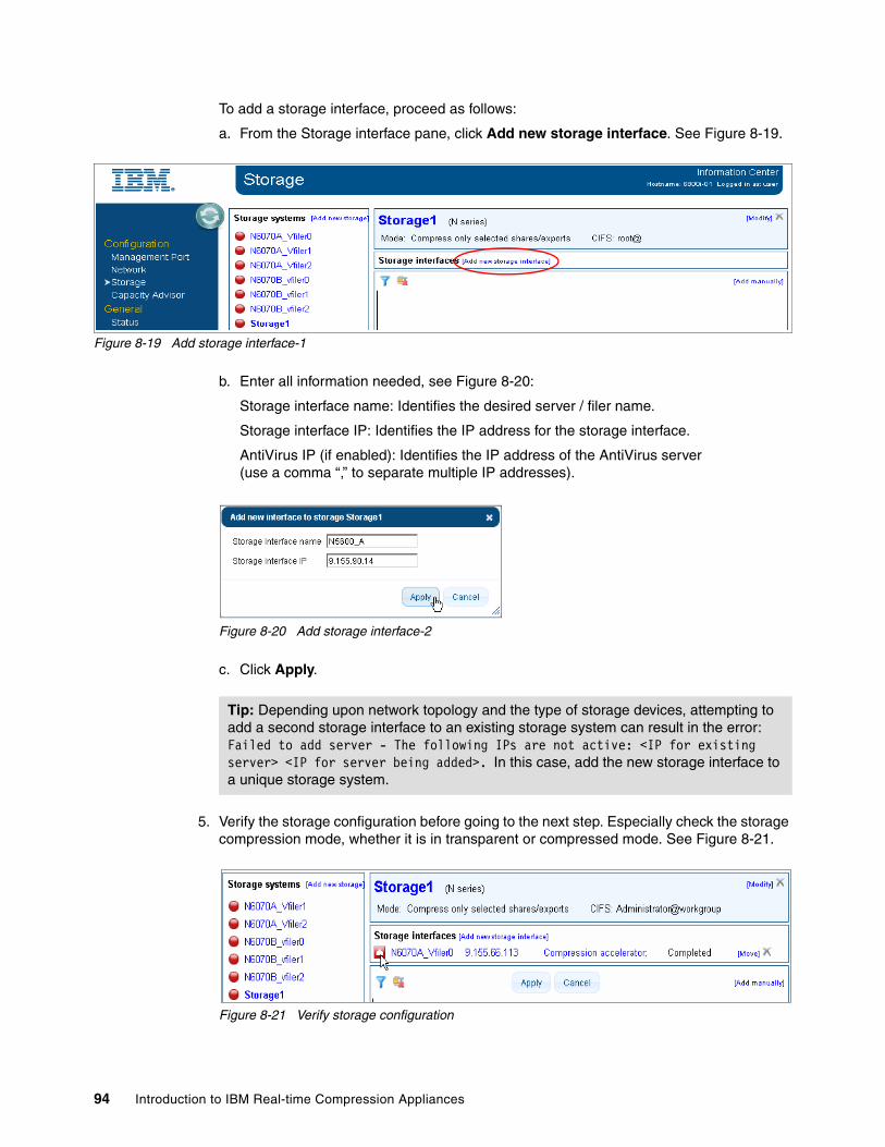
To add a storage interface, proceed as follows:
a. From the Storage interface pane, click Add new storage interface. See Figure 8-19.
Figure 8-19 Add storage interface-1
b. Enter all information needed, see Figure 8-20:
Storage interface name: Identifies the desired server / filer name.
Storage interface IP: Identifies the IP address for the storage interface.
AntiVirus IP (if enabled): Identifies the IP address of the AntiVirus server (use a comma “,” to separate multiple IP addresses).
Figure 8-20 Add storage interface-2
c. Click Apply.
5. Verify the storage configuration before going to the next step. Especially check the storage compression mode, whether it is in transparent or compressed mode. See Figure 8-21.
Figure 8-21 Verify storage configuration
Tip: Depending upon network topology and the type of storage devices, attempting to add a second storage interface to an existing storage system can result in the error: Failed to add server - The following IPs are not active: <IP for existing server> <IP for server being added>. In this case, add the new storage interface to a unique storage system.
94 Introduction to IBM Real-time Compression Appliances

8.5.5 Starting the compression engine
After we finish configuring bridges and storage subsystem with its storage interface, the RTCA engine can be started. To start the engine, proceed as follows:
1. On the navigation panel, click the Network link.
2. Click the Start Engine button to start up RTCA engine (see Figure 8-22).
Figure 8-22 RTCA compression engine
After a successful start, go on the Status Panel to see compression engine status (see Figure 8-23).
Figure 8-23 Checking the RTCA Engine status
Chapter 8. Deploying Real-time Compression Appliances 95
8.5.6 Summary of steps deploying RTCA
Here is a summary of quick steps needed to deploy RTCA into your storage environment:
1. Configure management IP address and security for configuring the RTCA:
Requirement:
– Monitor-mouse keyboard or serial console cable or UTP cross cable
– IP address for management IP, hostname
2. Configure bonds, bridges, and storage:
Requirement:
– Network high availability design for the storage. This also includes configuration on the network switch for which ports are to be plugged in for active-active port aggregation.
– UTP or FO cables. Additional number of cables depends on high availability design.
– IP addresses that must be on the same subnet as the storage IP address. Additional number of the new IP addresses depends the on number of bridges configured to the storage.
8.6 Configuring high availability
Continuous data access to network storage solutions involves a redundant and fault-tolerant network infrastructure and a highly available storage solution with built-in data protection features. The IBM Real-time Compression Appliance product integrates into all high availability topologies and configurations seamlessly, without introducing any new single point of failure or degradation of the service level offered by the storage and networking equipment.
If a network link of any of the bridge interfaces fails for any reason (such as switch powered off or cable disconnected), the corresponding NAS-connected port of the same bridge is shut down as well to reflect the status of the network. This feature makes the compression appliance consistent with the configuration in place before connecting the IBM Real-time Compression Appliance.
The following list summarizes four possible topologies for high availability:
� Active/passive at access path, defines path failover� Active/active link aggregation, using VIFs� Path failover using two switches� Clustered environment
Because IBM has developed a unique link status mirroring (LSM) feature to support various link aggregation and high availability configurations, this feature helps the compression appliance to integrate transparently and seamlessly into the high availability configuration in place. LSM reflects the link status of interfaces that are members of the same virtual bridge interface in the compression appliance configuration.
Keep in mind that the RTCA product will preserve performance and availability configurations for the back-end NAS. If the NAS configuration is not configured to assure high availability, the RTCA product will offer the same level after complete installation (that is, single filter configurations or VIFs created using single physical interfaces are not consider to be high availability topologies).
96 Introduction to IBM Real-time Compression Appliances

The high availability synchronization option allows you to export the compression appliance compression filters to a different appliance in a high availability configuration. There are manual and automatic modes for synchronizing a high availability configuration.
As described previously, there are two types of information that can be set on the RTCA product regarding the compression process:
� Compression Filters: Shares from the NAS storage that will be included in the compression process.
� File Extensions to exclude: Types of files that will not be compressed but will be “dropped” as they are on the share.
You have two options to configure the high availability function on the RTCA product: manually or automatically. Details are discussed in the following sections.
8.6.1 Synchronizing high availability manually
In order to create a manual synchronization, you have to export the current configuration of the filters from one appliance, and then import it on all other partner appliances.
Proceed as follows:
1. From the navigation menu, choose High Availability in order to open the High Availability panel (see Figure 8-24).
Figure 8-24 Configuring High Availability
Tip: When you configure a compression appliance in a high availability configuration, both appliances must have the same storage systems, the same storage interfaces, the same compression filters, and the same extension list.
Chapter 8. Deploying Real-time Compression Appliances 97

2. From the top menu, select MANUAL. In the new panel, select Exports For High Availability. Choose to save the *.stn file on a preferred path as shown in Figure 8-25.
Figure 8-25 Exporting the configuration for High Availability
3. Next, log in to the other compression appliance that you want to configure in the high availability configuration. Make sure you have prepared the file that was saved from the first appliance, and this time select Browse from the Import field. Locate your previously saved *.stn file and upload it on the new appliance (see Figure 8-26).
98 Introduction to IBM Real-time Compression Appliances

Figure 8-26 Importing the configuration for High Availability
If the configuration was imported successfully, the success message shown in Figure 8-27 will be displayed.
Figure 8-27 Notification import process finish
After a successful configuration, the newly added appliance will return to you a message with the new imported configurations.
Errors: The high availability configuration returns an error message in these situations:
� The Storage device, NAS, is not configured on all appliances that have access to it with the same name for the same share - different filters interpretation.
� The File extensions exclusions are configured differently on the appliances involved in high availability.
Chapter 8. Deploying Real-time Compression Appliances 99

Be aware that for a manual configuration, the modifications (new/deleted filters, and new file extension exclusions or extensions) made on one appliance will not be sent to the other partners automatically. You will have to export them and import them every time you are changing any settings.
8.6.2 Synchronizing high availability automatically
If you want to configure the high availability to update the changes automatically, you can configure the Management IPs on one appliance, and credentials for all other appliances. The distribution will be made automatically after that in a mesh topology.
Proceed as follows:
1. Starting at the Main panel, select the High Availability panel (see Figure 8-24) and choose the options that you want to be automatically synchronized between the HA partners: File Extensions and Filters.
2. Define the name that you want to appear on the other appliance as the high availability partner. This name is different than the one described before in 8.4, “Configuring the RTCA product” on page 80. This name function is only descriptive and is not mandatory to comply with the RTCA name, which is configured for management purposes.
3. In the “Remote Partner List” you must enter the IP address of the high availability partner together with the User name and password used to manage the partner appliance. After finishing completing these fields, select Apply Changes and Synchronize.
4. A message will confirm to you that the partner has been found, and the Shared Servers list will show you the common storage devices that are configured on both appliances (see Figure 8-28). For these storage devices, the appliances will exchange information every time when something is changed in the filters or file extension configuration.
Figure 8-28 Configuring the filters and file extension automatic synchronization
Tip: Be aware that all appliances must be able to communicate at the management interface level in order to synchronize the filters and file extension exclusions.
100 Introduction to IBM Real-time Compression Appliances

In case some file extensions or compression filters or firmware version are configured differently, the following error message displays. It asks you if the RTCA product can perform a forced configuration on the remote partner (see Figure 8-29).
Figure 8-29 High Availability Auto Synchronization Error message
If the synchronization error is still unsettled, RTCA cannot accept modification related to the compression configuration. Figure 8-30 is a sample of error message when configuring compression filters.
Figure 8-30 Partner are not in the same state
Chapter 8. Deploying Real-time Compression Appliances 101
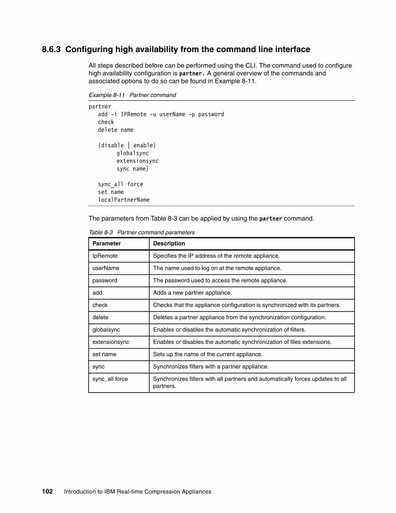
8.6.3 Configuring high availability from the command line interface
All steps described before can be performed using the CLI. The command used to configure high availability configuration is partner. A general overview of the commands and associated options to do so can be found in Example 8-11.
Example 8-11 Partner command
partner add -i IPRemote -u userName -p passwordcheckdelete name
{disable | enable} globalsyncextensionsync sync name}
sync_all forceset namelocalPartnerName
The parameters from Table 8-3 can be applied by using the partner command.
Table 8-3 Partner command parameters
Parameter Description
IpRemote Specifies the IP address of the remote appliance.
userName The name used to log on at the remote appliance.
password The password used to access the remote appliance.
add Adds a new partner appliance.
check Checks that the appliance configuration is synchronized with its partners.
delete Deletes a partner appliance from the synchronization configuration.
globalsync Enables or disables the automatic synchronization of filters.
extensionsync Enables or disables the automatic synchronization of files extensions.
set name Sets up the name of the current appliance.
sync Synchronizes filters with a partner appliance.
sync_all force Synchronizes filters with all partners and automatically forces updates to all partners.
102 Introduction to IBM Real-time Compression Appliances

An example regarding the usage of the partner command and configuration of high availability is presented in Example 8-12.
Example 8-12 Configuring high availability
[email protected]> partnerEnable Auto Sync: NoEnable File Extension Sync: NoAppliance HA Name: TestIP Name AutoSync LastSyncDate Shared Servers
[email protected]> partner enable globalsync
[email protected]> partner enable extensionsync
[email protected]> partner set name RtCA1
[email protected]> partnerEnable Auto Sync: YesEnable File Extension Sync: YesAppliance HA Name: RtCA1IP Name AutoSync LastSyncDate Shared Servers
[email protected]> partner add -i 9.155.66.157 -u user -p a1b2c3
[email protected]> partner sync RtCA2Partner synced successfully
[email protected]> partnerEnable Auto Sync: YesEnable File Extension Sync: YesAppliance HA Name: RtCA1
IP Name AutoSync LastSyncDate Shared Servers9.155.66.157 RtCA1 Yes Mon Oct 31 12:37:36 IST 2011 9.155.90.14,9.155.90.16
After configuring the RTCA bridges, bonds, and high availability functions, the next step in order to finish the installation of the device is to upgrade the firmware in case an upgrade is available.
Chapter 8. Deploying Real-time Compression Appliances 103

104 Introduction to IBM Real-time Compression Appliances

Chapter 9. Software installation or upgrade
In this chapter, we describe how to install or upgrade the RTCA software.
9
© Copyright IBM Corp. 2013. All rights reserved. 105

9.1 Before you begin
Currently, minor software release upgrades can be implemented without stopping the RTCA. For example, software updates for the web interface can be performed without stopping the compression engine. However, upgrades to other parts of the software might require restarting the compression engine or rebooting the system. Before you begin, be sure you have a valid configuration backup file.
For additional information about RTCA updates, also see the following online resource:
http://www.ibm.com/support/docview.wss?uid=ssg1S7003976
9.2 Obtaining the software file
To obtain the software file, go to the IBM Support website:
http://www.ibm.com/support
Ignore any pop-ups that might open.
To more quickly locate available downloads for your product, specify the full type and model or specify part of the type and model in the text box, as Figure 9-1 shows.
Figure 9-1 IBM Support website
Click the right angle bracket (>) next to the text box. You can then select your product, or the website selects it for you if you gave it enough details. For example, we typed STN, which was enough information to select the IBM Real-time Compression Appliance. See Figure 9-2.
Note: Download the installation file from the following website:
http://www.ibm.com/support/entry/portal
106 Introduction to IBM Real-time Compression Appliances

Figure 9-2 IBM Support website
After the correct product is selected, specify that you are looking for available downloads by clicking the Downloads section of the Choose your product menu (Figure 9-3).
The Downloads section of the selected product opens, as shown in Figure 9-3. Click View STN7500 RTCA STN6500-STN6800 downloads.
Figure 9-3 Downloads section
In the Available downloads, you can select the fix pack to upgrade the software. Select the check box next to the fix pack and click the Continue link.
There is always a license agreement to review and accept. Read it and agree with it so you can download the new software.
Note: When you use HTTP to download, right-click the link to the file and select Save As.
Chapter 9. Software installation or upgrade 107
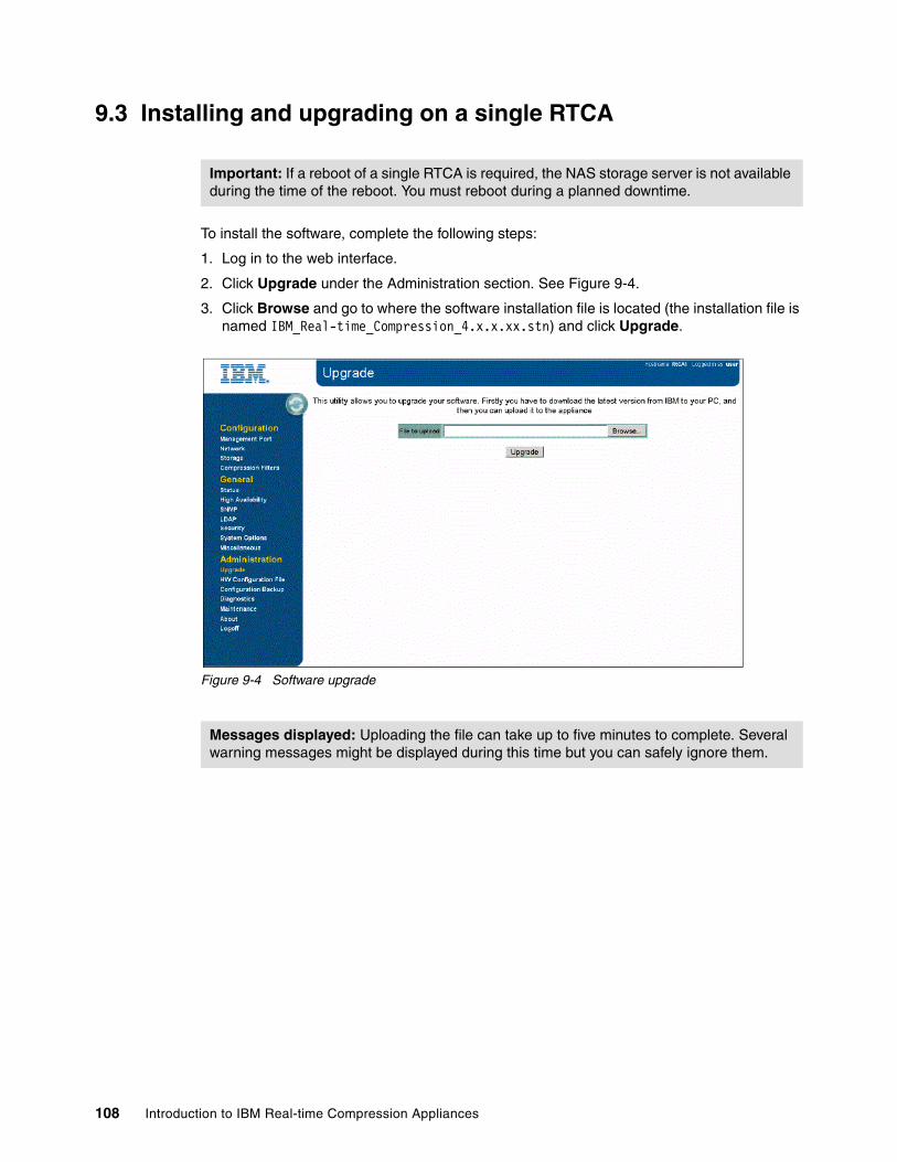
9.3 Installing and upgrading on a single RTCA
To install the software, complete the following steps:
1. Log in to the web interface.
2. Click Upgrade under the Administration section. See Figure 9-4.
3. Click Browse and go to where the software installation file is located (the installation file is named IBM_Real-time_Compression_4.x.x.xx.stn) and click Upgrade.
Figure 9-4 Software upgrade
Important: If a reboot of a single RTCA is required, the NAS storage server is not available during the time of the reboot. You must reboot during a planned downtime.
Messages displayed: Uploading the file can take up to five minutes to complete. Several warning messages might be displayed during this time but you can safely ignore them.
108 Introduction to IBM Real-time Compression Appliances
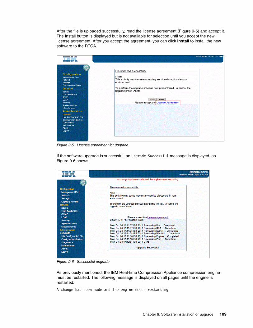
After the file is uploaded successfully, read the license agreement (Figure 9-5) and accept it. The Install button is displayed but is not available for selection until you accept the new license agreement. After you accept the agreement, you can click Install to install the new software to the RTCA.
Figure 9-5 License agreement for upgrade
If the software upgrade is successful, an Upgrade Successful message is displayed, as Figure 9-6 shows.
Figure 9-6 Successful upgrade
As previously mentioned, the IBM Real-time Compression Appliance compression engine must be restarted. The following message is displayed on all pages until the engine is restarted:
A change has been made and the engine needs restarting
Chapter 9. Software installation or upgrade 109

To restart, go to the Configuration Network and click Restart Engine. See Figure 9-7.
Figure 9-7 Network page of the IBM RTCA: A restart of the engine is necessary
The software upgrade completes.
After the engine is restarted, check the RTCA status panel. It lists the actual firmware level next to Version, under Device Information.
9.3.1 Installing and upgrading on a high availability RTCA system
When installing the software in a high availability environment, ensure that the same version is running on a partner RTCA system. To avoid any downtime on a high availability environment, you must install the software on one RTCA system after another:
1. Perform the same steps as described for installing on a single appliance. On the Status page, verify that the expected version is running after the engine restarted.
2. On a second appliance, perform the steps described for installing on a single appliance. On the Status page, verify that the expected version is running after the compression engine of the second appliance restarted.
Important: Make sure that there is no activity through the IBM Real-time Compression Appliance, or connectivity problems can occur.
Note: The bonds probe is displayed only when the system has configured bonds.
110 Introduction to IBM Real-time Compression Appliances

9.3.2 Updating the hardware configuration file
The RTCA requires a valid hardware configuration file. Typically the appliance is preinstalled with a proper hardware configuration file as part of the manufacturing process. However, you might have to update the hardware configuration file.
The Hardware Configuration File page enables updating of the compression appliance with details of the hardware configuration file, which specifies the hardware identity of the components in the appliance. Among other information, the hardware configuration file includes the amount of memory in the appliance, its serial number, and the hardware (MAC) addresses that is used in the network interfaces.
To update the hardware configuration file, complete the following steps:
1. Select the HW Configuration File option under the Administration section. See Figure 9-8.
2. If a hardware configuration file is not installed or provided, click Generate Hardware Configuration File Request first, save the file locally, and then send the file to IBM Support.
3. After IBM provides the new hardware configuration file, you can upload it by clicking Browse and searching for your hardware configuration file.
4. Select the hardware configuration file, and then click Upload.
Figure 9-8 Hardware configuration file
Chapter 9. Software installation or upgrade 111

9.3.3 Configuring system options
To modify general options for the IBM RTCA product, select System Options, under General, as shown in Figure 9-9.
Figure 9-9 System options
The following options are accessible:
� WebGui: The default setting is normal mode. If you change to debug mode, additional debug information is displayed at the top of each page.
� JavaScript: Choose Enable or Disable to activate or stop the use of JavaScript in the web interface pages. JavaScript is mainly used for pop-ups when you use the web interface. The default setting is enabled.
� Network Traffic Capture line: This option shows the status of the tcpdump network capture. This line only displays the status of the tcpdump option; to activate tcpdump, select Diagnostics panel Run tcpdump.
112 Introduction to IBM Real-time Compression Appliances

� Enable modifying network interface broadcast address: Use this option to enable or disable the user from modifying the broadcast address for the management and bridge interfaces. By default, this option is disabled. If you enable this option, the Broadcast field on the Management Port and Modify Bridge pages is enabled. See Figure 9-10.
Figure 9-10 Broadcast field
� Allow user to set factory defaults: This option prevents the user from restoring the IBM Real-time Compression Appliance configuration to factory settings. By default, this option is disabled. If you enable this option, a Restore Factory Defaults link becomes available in the Configuration Backup panel.
� Allow multiple users: Enable or disable access to the web interface from multiple client IP addresses. If this option is enabled (default), multiple users can log in and use the web interface concurrently. If you disable this feature, when an additional client accesses the appliance, the following message is displayed on the login page:
Someone else on IP_address is already logged in. Logging in will terminate the other session.
� Antivirus: Enable or disable support for storage-server-based antivirus products. By default, this option is enabled.
Attention: The broadcast address is assigned automatically by the management interface; modifying the broadcast address is typically not required. Consult with your network administrator before you change the broadcast address.
Attention: Restoring the factory defaults erases all your settings and completely stops the traffic through the appliance. Compressed data becomes available after you configure the RTCA back to your own settings.
Chapter 9. Software installation or upgrade 113

� Antivirus server IPs: Enable or disable support for specific McAfee virus scanning products. By default, support is disabled. If this option is enabled, a new Antivirus Server IP column is displayed in the Storage panel. See Figure 9-11.
Figure 9-11 System Options - Change Antivirus Server IPs
� Watchdog: Enable or disable the hardware watchdog feature. By default, this option is enabled.
� Guardian: Enable or disable the guardian process that automatically recovers from engine failures. By default, this option is enabled.
� CA Full Scan: Enable or disable the Compression Accelerator feature from the Storage panel that enables the user to compress existing data. By default, this option is enabled. If you disable this feature, the result might be that a volume will have both compressed and uncompressed data. Do not disable this feature unless instructed by IBM Support.
� LSM: Enable or disable the link status mirroring (LSM) feature. By default, this feature is enabled. Do not disable this feature unless instructed by IBM Support.
� Web GUI Access: Enable or disable the protocol used for GUI management. The HTTP-only mode allows only standard HTTP (port 80) access to the web interface; HTTPS-only allows only secured HTTP (port 443) access to the web interface. HTTP or HTTPs (the default) accepts either.
� Task Affinity: Enable or disable the automatic tuning of CPU affinity. By default, this feature is enabled for highest performance as internal modules of the compression appliance are balanced across the CPU cores using optimal CPU affinity. Do not disable this feature unless instructed by IBM Support.
Guardian and Watchdog difference: Although Guardian and Watchdog features can both operate with traffic interruption, the difference between them is as follows:
� Guardian can restart the process based on ID only when and if that process hangs.� Watchdog issues a complete restart and initialization of the hardware machine.
Because both processes are disruptive, do not disable them unless instructed by IBM Support.
Tip: The web interface supports HTTP and HTTPS. To configure HTTPS certificates, use the same procedure described in “Setting Up SSH authentication” in IBM Real-time Compression Appliances CLI Command Reference Version 4 Release 1, GA32-2219-01.
114 Introduction to IBM Real-time Compression Appliances

� HA gratuitous ARP: Enable or disable support for passing gratuitous ARP messages. By default, this feature is enabled. Do not disable this feature unless instructed by IBM Support.
� HA ARP mode refresh: Enable or disable support for high availability environments. By default, this feature is enabled. Do not disable this feature unless instructed by IBM Support.
� Extension Filters Mode: Choose Include or Exclude to configure the mode in which the extension filters are applied. By default, the extension filters that are configured and listed at the bottom of the Compression Filters panel define which extensions are excluded from compression (this is the Exclude mode). If Include is configured, the appliance compresses only files with extensions that are defined in the list.
� Unicast ARP Mangle: Enable or disable support for passing unicast ARP messages. By default, this feature is enabled. Do not disable this feature unless instructed by IBM Support.
� Vif Single Probe: Enable or disable support for Data ONTAP single VIF configurations. By default, this feature is disabled. Do not enable this feature unless instructed by IBM Support.
� User Autosupport Scheduling: Allow or prevent the user from modifying the default schedule for Autosupport reports. By default, this feature is enabled.
� Forced reboots: Enable or disable the forced reboots after frequent engine restarts. This option is applicable only for high availability configurations (in single appliance configurations, frequent engine warm restarts eventually become cold restarts; in high availability configurations, the warm restarts become forced reboots if the partner appliance and also its engine are running). By default, this option is enabled.
� SMB2 Pass Thru Support: Enable or disable the support for SMBv2-based CIFS sessions. By default, this option is disabled; CIFS sessions from SMBv2-enabled clients (such as Windows Vista, Windows 7, or Windows Server 2008) are downgraded automatically to SMBv1 protocol.
� Compress New Files: This setting does not change the behavior of the storage system compression mode, which pertains strictly to how new files are created. Use the Compress new files mode in cases where it is important to preserve the system maintenance operations and the current state of shares. For example, a storage system IP address is configured as Compress shares/exports except selected in its Compression Mode field, and the storage administrator wants to create a share that must work in uncompressed mode, so a compression filter is created after the share is created on the storage.
� Compressed mode: This feature changes the default behavior of RTCA when new storage is added.
From the CLI, use the options command followed by the appropriate option and either the on or off parameter to enable or disable that feature as presented Example 9-1.
Values 0 and 1: A value of 0 (zero) is associated with the off option; a value of 1 is
assimilated with the on option.
Chapter 9. Software installation or upgrade 115
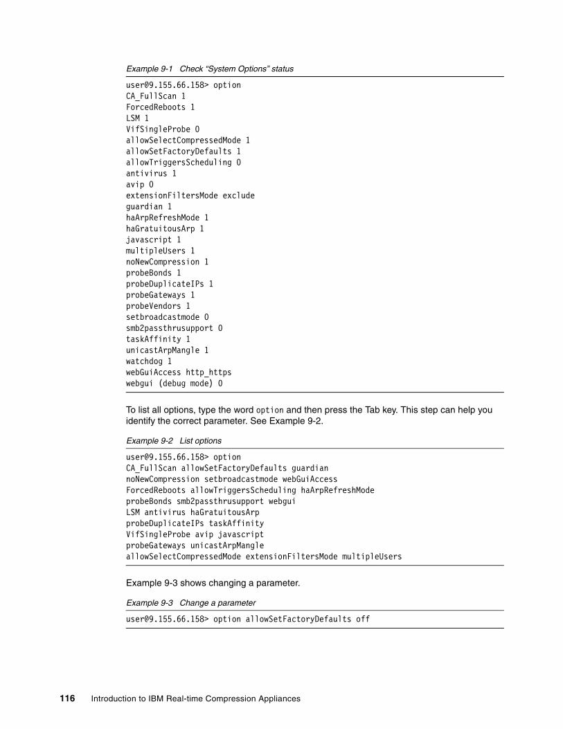
Example 9-1 Check “System Options” status
[email protected]> optionCA_FullScan 1ForcedReboots 1LSM 1VifSingleProbe 0allowSelectCompressedMode 1allowSetFactoryDefaults 1allowTriggersScheduling 0antivirus 1avip 0extensionFiltersMode excludeguardian 1haArpRefreshMode 1haGratuitousArp 1javascript 1multipleUsers 1noNewCompression 1probeBonds 1probeDuplicateIPs 1probeGateways 1probeVendors 1setbroadcastmode 0smb2passthrusupport 0taskAffinity 1unicastArpMangle 1watchdog 1webGuiAccess http_httpswebgui (debug mode) 0
To list all options, type the word option and then press the Tab key. This step can help you identify the correct parameter. See Example 9-2.
Example 9-2 List options
[email protected]> optionCA_FullScan allowSetFactoryDefaults guardiannoNewCompression setbroadcastmode webGuiAccessForcedReboots allowTriggersScheduling haArpRefreshModeprobeBonds smb2passthrusupport webguiLSM antivirus haGratuitousArpprobeDuplicateIPs taskAffinityVifSingleProbe avip javascriptprobeGateways unicastArpMangleallowSelectCompressedMode extensionFiltersMode multipleUsers
Example 9-3 shows changing a parameter.
Example 9-3 Change a parameter
[email protected]> option allowSetFactoryDefaults off
116 Introduction to IBM Real-time Compression Appliances

Chapter 10. Administration
In this chapter, we provide information about how you can use the web interface to further configure the IBM Real-time Compression Appliance (RTCA) after hardware installation and initial configuration.
As a reference for installation and initial configuration topics, see the IBM Real-time Compression Appliances Installation and Planning Guide.
For more details on how to use the command line interface, see the IBM Real-time Compression Appliances CLI Command Reference.
10
© Copyright IBM Corp. 2013. All rights reserved. 117

10.1 Working with the IBM Real-time Compression Appliance
After hardware installation and initial configuration, you can use the web interface to further configure the IBM Real-time Compression Appliance (RTCA).
10.1.1 The web interface
This topic provides a brief overview of the IBM Real-time Compression Appliance web-based administration tool. It describes the elements of the compression appliance web-based administration tool.
Each page in the web interface has a structure that is consistent with the page that is displayed in Figure 10-1, including a menu pane and an input area. The link in the lower right corner displays the direction to the next step and displays only on some pages.
Figure 10-1 IBM Real-time Compression Appliance web interface
10.1.2 The menu
The main page has a menu bar on the left that consists of three main menu options: Configuration, General, and Administration.
The Configuration menu contains the following options:
� Management Port: Used for configuring the compression appliance management port.
� Network: Used for configuring the compression appliance data ports, creating bonds and bridges, and stopping and starting the compression engine.
118 Introduction to IBM Real-time Compression Appliances

� Storage: Used for configuring which storage systems the compression appliance connects to. Also for configuring which CIFS shares and NFS exports have to be compressed.
� Configure Compression Accelerator. Used for configuring the Compression Accelerator.
� Capacity Advisor: Used to scan the storage systems and to report on capacity savings and expected growth.
The General menu contains the following options:
� Status: This page provides an overview of the compression appliance configuration, status, network ports, and resource utilization. This is also the main page displayed after the login is performed.
� High Availability: Used for configuring the high availability of the compression appliance.
� SNMP: Used for configuring SNMP settings.
� LDAP: Used for configuring LDAP settings.
� Security: Used for changing the compression appliance login password and specifying the IP addresses that can access the management interface.
� System Options: Used for configuring various settings, such as web interface access protocol (HTTP and HTTPS), SNMP and other compression engine settings.
� Miscellaneous: Used for setting the current date, time, and web interface session time-out; resetting the statistics counters; and configuring remote syslog servers.
The Administration menu contains the following options:
� Upgrade: Used for upgrading the software version. For more information, see Upgrading the compression appliance software.
� HW Configuration File: Used for installing and reviewing the compression appliance hardware configuration file.
� Configuration Backup: Used for saving or restoring the compression appliance configuration settings. For more information, see “Backing up the configuration.”
� Diagnostics: Used for saving system logs and downloading diagnostic information.
� Maintenance: Used for either shutting down or rebooting the system.
� About: Used for viewing details of the software components versions installed.
� Logoff: Used for logging out of the web interface.
10.1.3 Input area
Each page displays information according to the selected menu option. Parameters and other information items are displayed and can be configured here.
The next step to be performed is displayed in the lower right-hand corner of each page and is optional (see Figure 10-1 on page 118).
Reference: See the IBM Real-time Compression Appliances Installation and Planning Guide for information about configuring remote management, bonds, bridges, storage servers, and compression filters.
Chapter 10. Administration 119
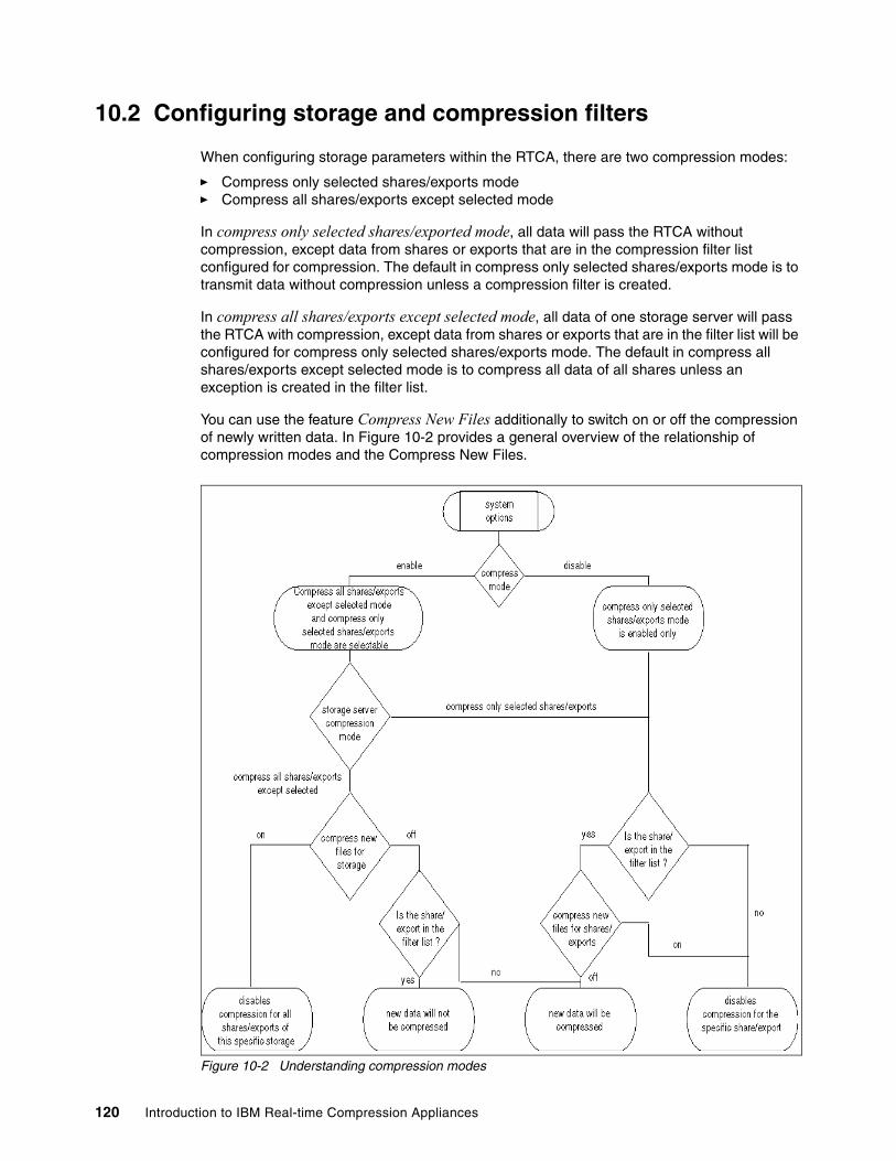
10.2 Configuring storage and compression filters
When configuring storage parameters within the RTCA, there are two compression modes:
� Compress only selected shares/exports mode� Compress all shares/exports except selected mode
In compress only selected shares/exported mode, all data will pass the RTCA without compression, except data from shares or exports that are in the compression filter list configured for compression. The default in compress only selected shares/exports mode is to transmit data without compression unless a compression filter is created.
In compress all shares/exports except selected mode, all data of one storage server will pass the RTCA with compression, except data from shares or exports that are in the filter list will be configured for compress only selected shares/exports mode. The default in compress all shares/exports except selected mode is to compress all data of all shares unless an exception is created in the filter list.
You can use the feature Compress New Files additionally to switch on or off the compression of newly written data. In Figure 10-2 provides a general overview of the relationship of compression modes and the Compress New Files.
Figure 10-2 Understanding compression modes
120 Introduction to IBM Real-time Compression Appliances

10.2.1 Compression filters in compress only selected shares/exports mode storage systems
In previous releases, when users added NFS exports to the exclude list, the GUI did not display the subexport as un-compressed.
To avoid misleading information, the NFS subexport is added to the filter list to protect the data from “clear” access, not through the compression engine.
Figure 10-3 shows the NFS subexport as un-compressed.
Figure 10-3 NFS export including subdirectories
It is best to use compress only selected shares/exports mode in the following circumstances:
� You have many NAS resources at your NAS storage server that must not be compressed, such as data compressed by content management application in many shares.
� You also want to compress only a part of your NAS storage server.
To configure the compression filters under compress only selected shares/exports mode, proceed as follows:
1. Configure that storage subsystem to use compress only selected shares/exports mode.
2. Use the “Storage” link to configure the compression of shares/exports filters. It lists all CIFS shares and NFS exports defined on the storage subsystems. See Figure 10-4.
Chapter 10. Administration 121

Figure 10-4 Configuring compression filters in compress only selected shares/exports mode
3. To add a new compressed share or export, select the check box that lists all defined shares or exports. Any changes on the filter list will cause the Apply and Cancel buttons to appear. Click the Apply button to activate compression share or export. Additionally, you can add some file extension in the “Extension to exclude” field to avoid double compressing of compressed data.
Configuration of the Compress New Files switch works as follows:
– If you set the Compress New Files option to “off”, all new data in the corresponding share/export will be compressed.
– If you set the Compress New Files option to “on”, any new written data will not be compressed.
See Figure 10-5 for compression filters.
122 Introduction to IBM Real-time Compression Appliances

Figure 10-5 Add compression shares or exports
4. To remove a compressed share/export from the filter list, uncheck the check box of the corresponding share/export and click Apply.
See the CLI in Example 10-1 for lists all of the available CIFS shared directories using the command: filter list available.
Check all configured filters using the command: filter list.
Example 10-1 List CIFS shared directories
[email protected]> storageStorage Storage If Name Storage Vendor Storage IP Mode No New Compression StatusStorage1 N5600_A N_series 9.155.90.14 Transparent - ActiveStorage2 N5600_B N_series 9.155.90.16 Compressed off Active
Tips:
� If you delete a share/export from the list, all data will be unchanged and presented to the clients directly without passing the compression engine. If the share/export contain compressed data, you can only access them after manual recovery. See “Recovering files when appliance is unavailable” on page 178.
� The column Compress New Files is only displayed if the system option “Compress New Files” is set to enabled.
Shares/exports compression filters
Configuration for Compress New Files
Chapter 10. Administration 123

[email protected]> filter list available -t cifs\\Storage1\HOME\\Storage1\tpch\\Storage2\HOME\\Storage2\cifs_home\\Storage2\cifs_vol1\\Storage2\cifs_vol2\\Storage2\test_vol1
[email protected]> filter list -t cifsCompression Mode No New Compression Warnings Share/ExportTransparent - - \\Storage2\ADMIN$Transparent - - \\Storage2\C$Transparent - - \\Storage2\D$Transparent - - \\Storage2\E$Transparent - - \\Storage2\ETC$Transparent - - \\Storage2\F$Transparent - - \\Storage2\HIDDEN$Transparent - - \\Storage2\IPC$
On the CLI, check first in which mode the storage is configured (compress all shares/exports except selected or compress only selected shares/exports). In a compress only selected shares/exports mode storage system, adding share or export into compression filters will make that directory into compress all shares/exports except selected mode. See Example 10-2.
Example 10-2 Creating compression filter for CIFS in compress only selected shares/exports mode
[email protected]> filter add Storage1 -c nocheck -t cifs [email protected]> filter list -t cifsCompression Mode No New Compression Warnings Share/ExportCompressed Off - \\Storage1\tpchTransparent - - \\Storage2\ADMIN$Transparent - - \\Storage2\C$Transparent - - \\Storage2\D$Transparent - - \\Storage2\E$Transparent - - \\Storage2\ETC$Transparent - - \\Storage2\F$Transparent - - \\Storage2\HIDDEN$Transparent - - \\Storage2\IPC$
10.2.2 Compression modes
In previous releases, the Transparent/Compress mode and No-New-Compression could be attached, but was ambiguous. To create a clear meaning, the RTCA terminology is revised in the GUI.
This options set the operation mode for new files that are created on a storage interface. When the Compress new files option is disabled, shares that are configured to work in compressed mode have existing files read and updated based on their current state (compressed or uncompressed), but new files are created as uncompressed files.
124 Introduction to IBM Real-time Compression Appliances

This setting does not change the behavior of the storage system compression mode, which pertains strictly to how new files are created. Use the Compress new files mode in cases where preserving the system maintenance operations and the current state of shares is important. For example, if a storage system IP address is configured as Compress shares/exports except selected in its Compression Mode field, and the storage administrator wants to create a share that must work in uncompressed mode, a compression filter is created after the share is created on the storage.
Configure the system in Compress new files disabled mode before you add the share to avoid creating compressed files on the storage; then enable Compress new files after the share is added to the compression filters exclude list.
Table 10-1 provides the mapping between old to new terminology.
Table 10-1 New terminology
Figure 10-6 shows a sample of the new terminology in the GUI interface.
Figure 10-6 New terminology in GUI
10.2.3 Changing the storage system mode from compress only selected shares/exports to compress all shares/exports except selected
When RTCA’s storage mode for a specific NAS controller is changed to “compress all shares/exports except selected”, then all NAS access (CIFS shares and NFS exports) will be compressed by default.
When converting a storage system from compress only selected shares/exports mode to compress all shares/exports except selected mode, the compression filters for this storage system will be modified accordingly to preserve the existing configuration.
CLI unchanged: The CLI remains as before so changes are not required for scripts.
New terminology Old terminology
Compress all shares/exports except selected, Compress only selected shares/exports
Compressed, Transparent
Compress New Files No New Compression
Chapter 10. Administration 125

Follow these steps to change the NAS controller to storage compress all shares/exports except selected mode:
1. Log in to the RTCA web interface.
2. In the left-hand menu, under Configuration, select Storage.
3. In the Storage systems view, select your NAS controller:
This will update the screen to show the current compression mode.
4. In the top right corner of the storage display, as shown in Figure 10-7, select [Modify].
Figure 10-7 Modifying storage
5. When the “Modify storage parameters” dialog box appears, as shown in Figure 10-8:
a. Select “compress all shares/exports except selected” in the Compression mode field.
b. Click Apply.
Figure 10-8 Parameters on modifying storage
6. When the dialog box updates with a warning message, as shown in Figure 10-8, be sure to read the warning message before continuing with this process.
Also notice the “Compress New Files” field that appears, and which cannot be changed from “On”. We will modify this field later to enable compression.
Important: The switch from compress only selected shares/exports mode to compress all shares/exports except selected mode is a one-way process. It is not possible to change back to compress only selected shares/exports mode.
Be sure that you understand the impact of changing this mode before continuing.
126 Introduction to IBM Real-time Compression Appliances
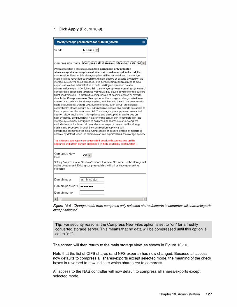
7. Click Apply (Figure 10-9).
Figure 10-9 Change mode from compress only selected shares/exports to compress all shares/exports except selected
The screen will then return to the main storage view, as shown in Figure 10-10.
Note that the list of CIFS shares (and NFS exports) has now changed. Because all access now defaults to compress all shares/exports except selected mode, the meaning of the check boxes is reversed to now indicate which shares not to compress.
All access to the NAS controller will now default to compress all shares/exports except selected mode.
Tip: For security reasons, the Compress New Files option is set to “on” for a freshly converted storage server. This means that no data will be compressed until this option is set to “off”.
Chapter 10. Administration 127

10.2.4 Compression filters in compress all shares/exports except selected mode storage systems
In large environments with a lot of NAS resources that you want to compress, it can be easier to switch the system-wide policy to compress all shares/exports except selected mode. An additional advantage of compress all shares/exports except selected mode is the possibility to compress data of dynamic shares, such as home directory shares of NetApp FAS or IBM N series. For auto home shares, this is necessary because those shares will be included in the compressed behavior.
To configure compression filters in compress all shares/exports except selected mode, proceed as follows:
1. Configure the storage subsystem to use compress all shares/exports except selected mode (Figure 10-10).
Figure 10-10 Configuring compression filters in compress all shares/exports except selected mode
128 Introduction to IBM Real-time Compression Appliances

2. Check the storage parameter for “Compress New FIles” status. “Compress New Files” sets the operation mode for new files created on shares and exports marked for compression using the compression filters mechanism. After setting this mode to Off, new files will be created as compressed or non-compressed, based on the compression mode in the compression filters list. To start compression, turn off the parameter Compress New Files and then click the Apply button. See Figure 10-11.
Figure 10-11 Storage parameters for compress all shares/exports except selected mode
3. To add new filter shares or exports, select the check box that lists all defined shares or exports. Any changes on the filter check box list will make the Apply and Cancel buttons appear. Click the Apply button.
Administrators must check the compression filter exclusion list so that all administrative shares or exports are included. Otherwise, the RTCA product will store configuration files of the root directory or etc$ share as compressed files.
The CLI listing in Example 10-3 shows all available NFS export directories and all currently configured NFS export directories.
Example 10-3 Filter list for NFS export directories
[email protected]> storageStorage Storage If Name Storage Vendor Storage IP Mode No New Compression StatusStorage1 N5600_A N_series 9.155.90.14 Transparent - ActiveStorage2 N5600_B N_series 9.155.90.16 Compressed off Active
Precaution: Writing compressed data to administrative shares or exports, which contain the storage system's operating system and configuration parameters (such as /vol/vol0), can cause severe storage system functionality issues. If you have a virtual filer (vfiler) configured, it might be necessary to add the root qtrees/volumes of the vfiler manually.
Chapter 10. Administration 129

[email protected]> filter list available -t nfs Storage1:/vol/oracle/tpch Storage2:/vol/cifs_home Storage2:/vol/cifs_vol2 Storage2:/vol/iscsi_vol1 Storage2:/vol/nfs_vol1 Storage2:/vol/nfs_vol1/FreeBase Storage2:/vol/nfs_vol2 Storage2:/vol/vmware_iscsi_ds Storage2:/vol/vmware_vol Storage2:/vol/vol0 Storage2:/vol/vol0/[email protected]> filter list -t nfsCompression Mode No New Compression Warnings Share/ExportCompressed Off - Storage1:/vol/oracle/tpchTransparent - - Storage2:/vol/nfs_vol1/FreeBase
If the storage system is in compression mode with Compress New Files turned off, all files will be compressed by default, except for all shares defined in the filter lists. Example 10-4 shows how to add an NFS filter so that the export will be accessed in compress only selected shares/exports mode.
Example 10-4 Adding filter to NFS export in compress all shares/exports except selected mode
[email protected]> filter add Storage2 -t nfs /vol/vmware_volSucceeded
[email protected]> filter list -t nfsCompression Mode No New Compression Warnings Share/ExportCompressed Off - Storage1:/vol/oracle/tpchTransparent - - Storage2:/vol/nfs_vol1/FreeBaseTransparent - - Storage2:/vol/vmware_vol
10.3 Configuring the Compression Accelerator
This topic provides a description of configuration options to be used when configuring the Compression Accelerator feature.
Before you begin, configure the compression filters for the shares and exports that need to be compressed by Compression Accelerator.
By default, only newly written data is compressed on shares that are configured with compression filters; existing files that are not updated are not compressed. The Compression Accelerator feature on the Storage page can be configured to compress existing files in specified shares.
130 Introduction to IBM Real-time Compression Appliances

10.3.1 Compression Accelerator procedure
Following is a step-by-step process showing how to configure the Compression Accelerator:
1. On the Navigation menu, click the Storage link to display all available storage systems (see Figure 10-12). Click the Compression Accelerator link. The Compression Accelerator page opens.
Figure 10-12 Storage configuration
If the link is not active, ensure that the Compression Accelerator is enabled on the System Options page (see Figure 10-13).
Chapter 10. Administration 131
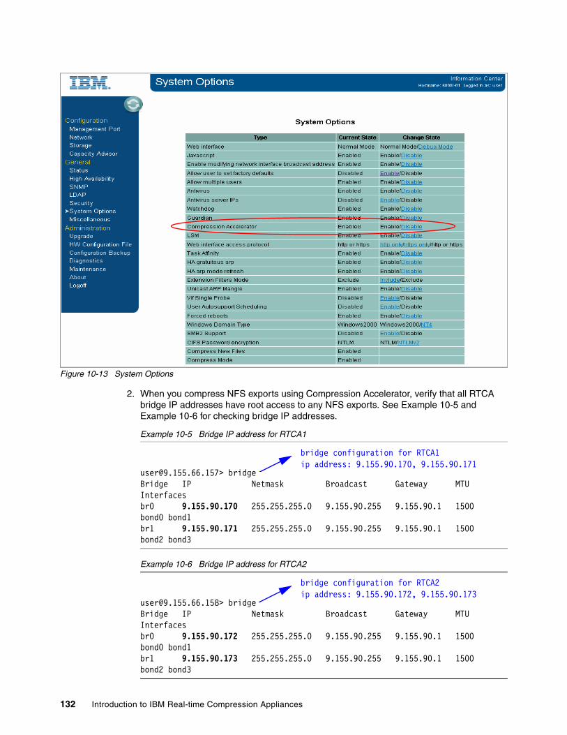
Figure 10-13 System Options
2. When you compress NFS exports using Compression Accelerator, verify that all RTCA bridge IP addresses have root access to any NFS exports. See Example 10-5 and Example 10-6 for checking bridge IP addresses.
Example 10-5 Bridge IP address for RTCA1
[email protected]> bridgeBridge IP Netmask Broadcast Gateway MTU Interfacesbr0 9.155.90.170 255.255.255.0 9.155.90.255 9.155.90.1 1500 bond0 bond1br1 9.155.90.171 255.255.255.0 9.155.90.255 9.155.90.1 1500 bond2 bond3
Example 10-6 Bridge IP address for RTCA2
[email protected]> bridgeBridge IP Netmask Broadcast Gateway MTU Interfacesbr0 9.155.90.172 255.255.255.0 9.155.90.255 9.155.90.1 1500 bond0 bond1br1 9.155.90.173 255.255.255.0 9.155.90.255 9.155.90.1 1500 bond2 bond3
bridge configuration for RTCA1ip address: 9.155.90.170, 9.155.90.171
bridge configuration for RTCA2ip address: 9.155.90.172, 9.155.90.173
132 Introduction to IBM Real-time Compression Appliances

See Example 10-7 for NFS export for root access given to bridge IP addresses.
Example 10-7 Root access to NFS exports
N5600-A> rdfile /etc/hosts#Auto-generated by setup Tue Sep 6 12:48:25 GMT 2011127.0.0.1 localhost9.155.90.14 N5600-A N5600-A-e0a# 0.0.0.0 N5600-A-e0b# 0.0.0.0 N5600-A-e0c# 0.0.0.0 N5600-A-e0d# 0.0.0.0 N5600-A-e4a# 0.0.0.0 N5600-A-e4b9.155.90.170 rtca2-br09.155.90.171 rtca2-br19.155.90.172 rtca1-br09.155.90.173 rtca1-br1
N5600-A> rdfile /etc/exports
#Auto-generated by setup Tue Sep 6 12:48:25 GMT 2011/vol/vol0-sec=sys,rw,anon=0,nosuid
/vol/vol0/home-sec=sys,rw,nosuid
/vol/vmware-sec=sys,rw=9.155.39.47:9.155.39.55:9.155.90.173:9.155.90.172:9.155.90.171:9.155.90.170:9.155.113.188,root=rtca1-br0:rtca1-br1:rtca2-br0:rtca2-br1:9.155.113.188:9.155.39.47:9.155.39.55
3. When you compress CIFS shares using the Compression Accelerator, configure a user name, password, and domain name in the CIFS user name, CIFS password, and CIFS domain fields, respectively, and click Apply Changes.
Important: Avoid adding the NAS root file system (for example, /vol/vol0 in N series systems) to the Compression Accelerator task list. Adding this file system to the task list can result in compression of the storage system files, which are read directly by the NAS system and therefore must remain uncompressed.
Tip: Configure a CIFS user with read/write permissions on files that are processed by the Compression Accelerator.
NFS export configuration forIBM N series
Ensure that bridge IP addresses have root access
Chapter 10. Administration 133

The Compression Accelerator supports various configuration parameters for scheduling, throttling, and policy-based file optimization that you can use to fine-tune the process. Figure 10-14 shows the Compression Accelerator Configuration items.
Figure 10-14 Compression Accelerator settings
The Shares tab allows you to select the CIFS shares on the storage to be compressed in place (Figure 10-15).
Figure 10-15 Shares tab configuration
134 Introduction to IBM Real-time Compression Appliances

The Exports tab allows you to select the NFS exports on the storage to be compressed in place (Figure 10-16).
Figure 10-16 Exports tab configuration
The Status tab allows you to manage and monitor compression tasks (Figure 10-17).
Figure 10-17 Compression Accelerator Status tab
Attention: Make sure Compress New Files is turned off for any storage system with which you plan to use the Compression Accelerator.
Chapter 10. Administration 135
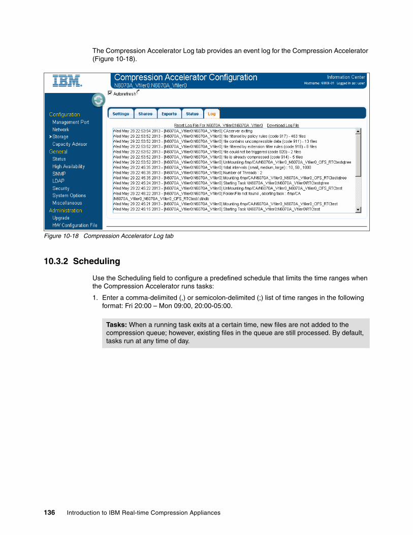
The Compression Accelerator Log tab provides an event log for the Compression Accelerator (Figure 10-18).
Figure 10-18 Compression Accelerator Log tab
10.3.2 Scheduling
Use the Scheduling field to configure a predefined schedule that limits the time ranges when the Compression Accelerator runs tasks:
1. Enter a comma-delimited (,) or semicolon-delimited (;) list of time ranges in the following format: Fri 20:00 – Mon 09:00, 20:00-05:00.
Tasks: When a running task exits at a certain time, new files are not added to the compression queue; however, existing files in the queue are still processed. By default, tasks run at any time of day.
136 Introduction to IBM Real-time Compression Appliances

2. Policy: Define a policy with a set of rules in the Policy field. You can define rules for file size, file access, create and modify time, or file extension. Combine rules into a more sophisticated policy using the logical operators and|or. Use the following syntax as shown in Example 10-8.
Example 10-8 Policy syntax
[size<operator><bytes>] [and|or] [[atime|ctime|mtime] <Operator> <YYYYMMDD>] [and|or] [ext='<FileExt>']
Operator Any of the following operators: < > =.
Bytes File size in bytes.
YYYYMMDD The file time stamp in the format: YYYY (year), MM (month), DD (day of week).
FileExt The file extension of the file.
Example:((size > 9000) or (ctime > 20080304)) and mtime=20080909 and ext ='doc'
The default policy is size > 512. Using the default, only files larger than a compressed file header size (512 bytes) are compressed.
3. Directories to Ignore: Define the subdirectories to ignore when the task is processed in the entire share or export using the Directories to Ignore field. Use this option for various types of snapshot or backup directories, which usually have the same name. It is sufficient to specify only a directory name and not its path. The default policy is as follows:
.snapshot ~snapshot .ckpt .isilon .ifsvar
4. Maximum Total Throughput: Define compression I/O throttling in MB/sec using the Maximum Total Throughput field. When the throughput of write I/O that is directed toward the NAS IP address that was configured on the Storage page reaches the limit specified in this field, the Compression Accelerator stops adding new files to its compression queue until the throughput drops below the specified threshold.
5. Amount of Changes: Define a quota (in MB/hours) for the aggregated changes that can be written to the NAS server within the defined number of hours using the Amount of Changes field. Define values that reflect the rate of change as observed on the NAS system; for example, in N series snap delta output.
6. Free Space Threshold: Set a minimum percentage of free space in the Free Space Threshold field and then click Apply Changes. Compression Accelerator In-Place tasks automatically pause if this threshold is exceeded. The default setting is 5%.
7. Interval Between Files: Define the interval (in milliseconds) between new files entering the Compression Accelerator queue using the Interval Between Files field. The value can be in the range 1 - 10000; the default value is 10 milliseconds. Increasing this value reduces the load on the storage; however, it slows the compression. Setting the interval to 1 millisecond provides the highest compression throughput.
NAS: The free disk space verification relies on reporting that is provided by the NAS. The NAS configuration items such as quotas can affect the behavior of this feature.
Chapter 10. Administration 137
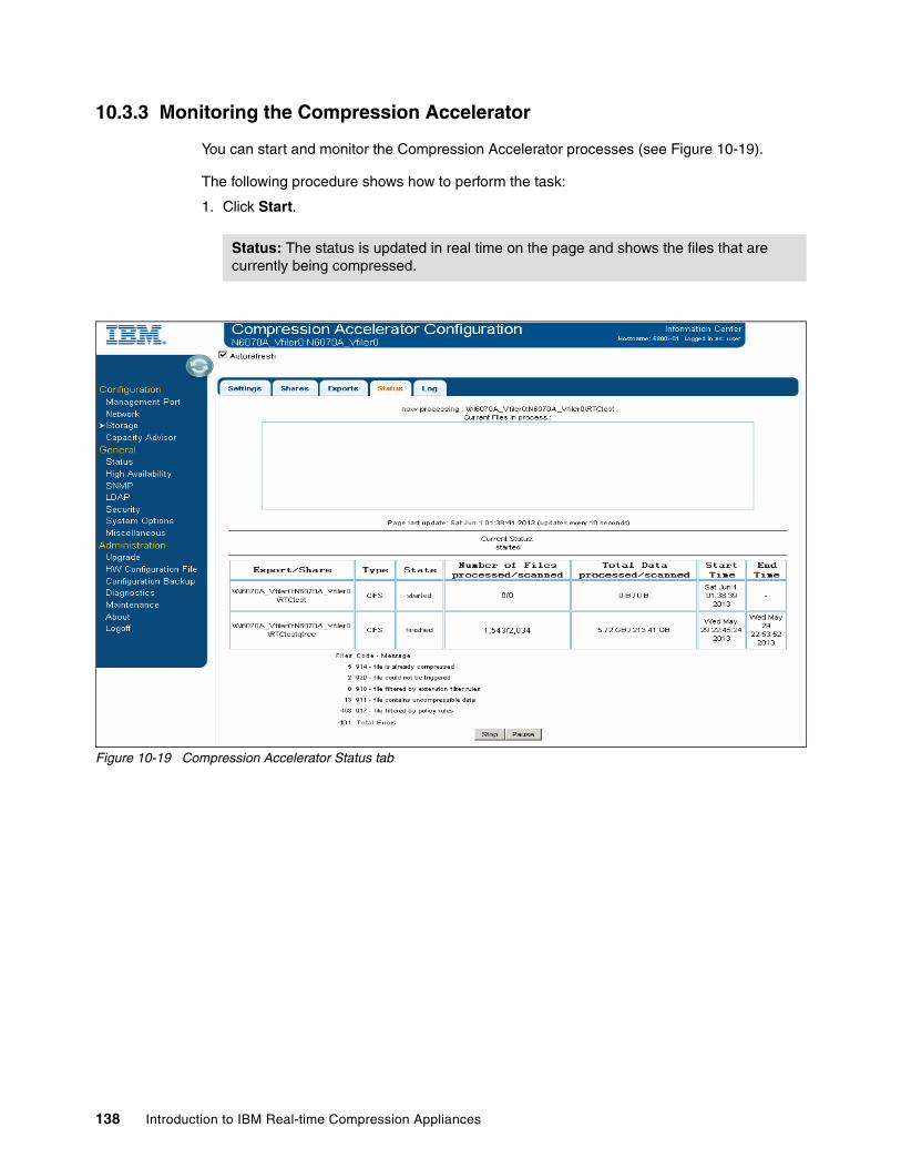
10.3.3 Monitoring the Compression Accelerator
You can start and monitor the Compression Accelerator processes (see Figure 10-19).
The following procedure shows how to perform the task:
1. Click Start.
Figure 10-19 Compression Accelerator Status tab
Status: The status is updated in real time on the page and shows the files that are currently being compressed.
138 Introduction to IBM Real-time Compression Appliances

2. Click Refresh in the upper-right corner of the menu to refresh the page.
3. View the Compression Accelerator status under Current Status. The following states are possible:
Not started The Compression Accelerator process has not started.
Pending The Compression Accelerator process is busy mounting an export.
Started The Compression Accelerator process has started.
Finished The Compression Accelerator process has finished processing all exports or shares and has now stopped.
4. View information about the configured compression tasks:
Export or Share The name of the export or share that is configured for compression.
Type NFS or CIFS
State The state of the compression task for this export or share; the following values are possible:
Not running The compression task for this export or share is not running.
Started The compression task is running.
Pending The compression task is pending, for example, when another task is running.
Paused The compression task is paused because a configured threshold has been reached.
Unmounting The compression task is disconnecting from the export or share.
Finished The compression task has finished.
Number of Files processed Total number of files that have been processed by the Compression Accelerator.
Number of Files scanned Total number of files that have been scanned by the Compression Accelerator.
Total Data processed Total amount of data that has been processed by the Compression Accelerator.
Total Data scanned Total amount of data that has been scanned by the Compression Accelerator.
Start Time The start time of the compression task.
End Time The end time of the compression task.
Chapter 10. Administration 139
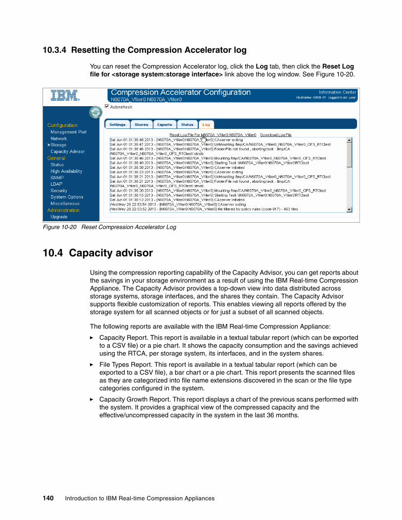
10.3.4 Resetting the Compression Accelerator log
You can reset the Compression Accelerator log, click the Log tab, then click the Reset Log file for <storage system:storage interface> link above the log window. See Figure 10-20.
Figure 10-20 Reset Compression Accelerator Log
10.4 Capacity advisor
Using the compression reporting capability of the Capacity Advisor, you can get reports about the savings in your storage environment as a result of using the IBM Real-time Compression Appliance. The Capacity Advisor provides a top-down view into data distributed across storage systems, storage interfaces, and the shares they contain. The Capacity Advisor supports flexible customization of reports. This enables viewing all reports offered by the storage system for all scanned objects or for just a subset of all scanned objects.
The following reports are available with the IBM Real-time Compression Appliance:
� Capacity Report. This report is available in a textual tabular report (which can be exported to a CSV file) or a pie chart. It shows the capacity consumption and the savings achieved using the RTCA, per storage system, its interfaces, and in the system shares.
� File Types Report. This report is available in a textual tabular report (which can be exported to a CSV file), a bar chart or a pie chart. This report presents the scanned files as they are categorized into file name extensions discovered in the scan or the file type categories configured in the system.
� Capacity Growth Report. This report displays a chart of the previous scans performed with the system. It provides a graphical view of the compressed capacity and the effective/uncompressed capacity in the system in the last 36 months.
140 Introduction to IBM Real-time Compression Appliances
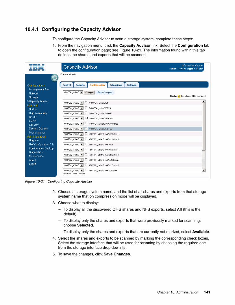
10.4.1 Configuring the Capacity Advisor
To configure the Capacity Advisor to scan a storage system, complete these steps:
1. From the navigation menu, click the Capacity Advisor link. Select the Configuration tab to open the configuration page; see Figure 10-21. The information found within this tab defines the shares and exports that will be scanned.
Figure 10-21 Configuring Capacity Advisor
2. Choose a storage system name, and the list of all shares and exports from that storage system name that on compression mode will be displayed.
3. Choose what to display:
– To display all the discovered CIFS shares and NFS exports, select All (this is the default).
– To display only the shares and exports that were previously marked for scanning, choose Selected.
– To display only the shares and exports that are currently not marked, select Available.
4. Select the shares and exports to be scanned by marking the corresponding check boxes. Select the storage interface that will be used for scanning by choosing the required one from the storage interface drop down list.
5. To save the changes, click Save Changes.
Chapter 10. Administration 141
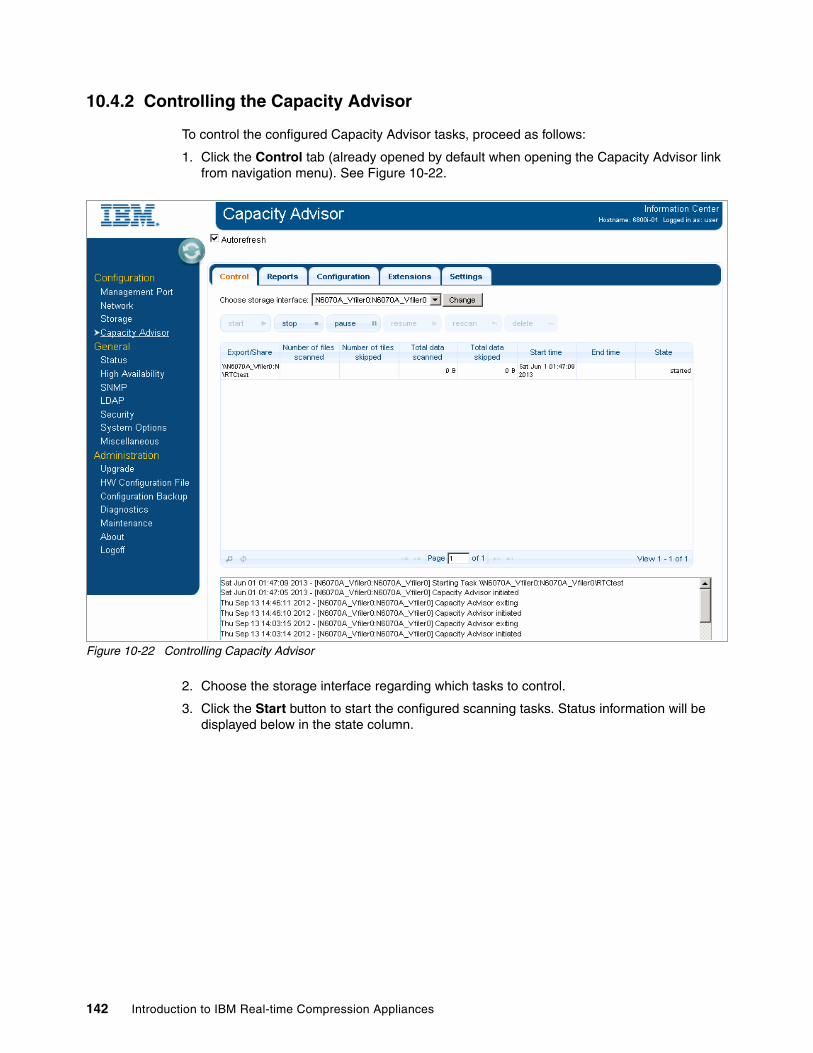
10.4.2 Controlling the Capacity Advisor
To control the configured Capacity Advisor tasks, proceed as follows:
1. Click the Control tab (already opened by default when opening the Capacity Advisor link from navigation menu). See Figure 10-22.
Figure 10-22 Controlling Capacity Advisor
2. Choose the storage interface regarding which tasks to control.
3. Click the Start button to start the configured scanning tasks. Status information will be displayed below in the state column.
142 Introduction to IBM Real-time Compression Appliances

10.4.3 Scheduling the Capacity Advisor
To schedule the configured Capacity Advisor tasks, proceed as follows:
1. On the Capacity Advisor page, click the Settings tab to open the schedule page. It displays schedule information for each storage interface. See Figure 10-23.
Figure 10-23 Setting schedule on Capacity Advisor
2. Set the schedule for each storage interface in which Capacity Advisor scanning will take place. Scheduling parameters take the following format: Comma or semicolon delimited list of time ranges, where the Capacity Advisor will run tasks. When a running task exits a time window, existing files will still be scanned; however, no new files will be added to the scanning queue.
For example: Thu 17:00 - Mon 09:00, 20:00 - 05:00, Wed 07:00 - Wed 07:30 or using weekdays (that is, Sun 10:00 - Mon 12:00). Several intervals can be inserted, as long as they are delimited by a comma or a semicolon.
3. Also configure the directories to ignore. This defines the subdirectories to ignore when the task is processed in the entire share or export using the Directories to Ignore field. Use this option for various types of snapshot or backup directories, which usually have the same name. It is sufficient to specify only a directory name and not its path.
4. Select the Control tab and select the required storage interface. Click the Start button. The scheduled tasks will start scanning, according to the configured schedules.
Tip: If a schedule not specified, tasks will run immediately when started.
Chapter 10. Administration 143
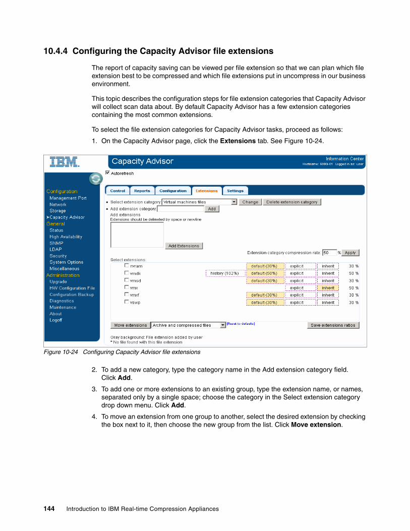
10.4.4 Configuring the Capacity Advisor file extensions
The report of capacity saving can be viewed per file extension so that we can plan which file extension best to be compressed and which file extensions put in uncompress in our business environment.
This topic describes the configuration steps for file extension categories that Capacity Advisor will collect scan data about. By default Capacity Advisor has a few extension categories containing the most common extensions.
To select the file extension categories for Capacity Advisor tasks, proceed as follows:
1. On the Capacity Advisor page, click the Extensions tab. See Figure 10-24.
Figure 10-24 Configuring Capacity Advisor file extensions
2. To add a new category, type the category name in the Add extension category field. Click Add.
3. To add one or more extensions to an existing group, type the extension name, or names, separated only by a single space; choose the category in the Select extension category drop down menu. Click Add.
4. To move an extension from one group to another, select the desired extension by checking the box next to it, then choose the new group from the list. Click Move extension.
144 Introduction to IBM Real-time Compression Appliances
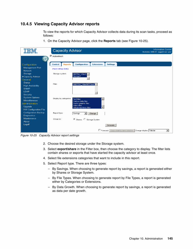
10.4.5 Viewing Capacity Advisor reports
To view the reports for which Capacity Advisor collects data during its scan tasks, proceed as follows:
1. On the Capacity Advisor page, click the Reports tab (see Figure 10-25).
Figure 10-25 Capacity Advisor report settings
2. Choose the desired storage under the Storage system.
3. Select export/share in the Filter box, then choose the category to display. The filter lists contain shares or exports that have started the capacity advisor at least once.
4. Select file extensions categories that want to include in this report.
5. Select Report type. There are three types:
– By Savings. When choosing to generate report by savings, a report is generated either by Shares or Storage System.
– By File Types. When choosing to generate report by File Types, a report is generated either by Categories or Extensions.
– By Data Growth. When choosing to generate report by savings, a report is generated as data per date growth.
Chapter 10. Administration 145

6. Click Generate when finished configuring the report. See Figure 10-26 for a sample result generated for each file extension name.
Figure 10-26 Sample result of Capacity Advisor by File Types
146 Introduction to IBM Real-time Compression Appliances
10.5 High availability concepts
The high availability (HA) concept for the IBM RTCA refers to both the appliance configuration and external environment configuration. Because the IBM RTCA is acting as an “intelligent cable” without involvement in the TCP/IP traffic management, but only reducing the amount of data from IP frames, the way high availability is implemented is different from other similar implementations. When you configure a compression appliance in a high availability configuration, both appliances must have the same compression filters because the data flows are not under RTCA care but more on the network and storage mechanism.
The important aspect in RTCA HA implementation is to be sure that if failover occurs and the data becomes accessible over the second appliance, the filters are also in place and users will not connect directly to an uncompressed volume.
Another very important aspect is the configuration of the appliance behavior as Compress or Not Compress and Compress New Files activation.
10.6 Monitoring the compression appliance
The management of the RTCA can be done by using the CLI or GUI. For most use cases, the GUI will provide an easier approach, but we also describe the CLI commands used in our examples. The main tasks for management are as follows:
� Displaying compression appliance status: Provides compression appliance status information available on the Status page.
� Displaying storage status: Reviews information about the connectivity status of each file server or NAS.
� Displaying compression status: Describes how to display information about the compression engine, including the status of the shares and exports and the file name extensions excluded from compression.
� Configuring SNMP: Shows how to configure and modify the SNMP configuration settings.
� Configuring LDAP: Shows how to configure and modify the LDAP notification settings.
� Performing other compression appliance tasks: Allows you to set the time and date, reset compression statistics, configure the web interface session time-out, configure an external syslog server, and configure DNS.
In the following sections, we describe these main tasks in detail.
Important considerations:
� When synchronizing the filters, you need to know that if there are differences, the filters from the target appliance or partner will be deleted and replaced with the filters from the initiator of the sync procedure. In this situation, if on the target appliance there are some filters that are not created on the sync initiator, those filters will be lost and the compressed volumes can become accessible directly by the user.
� In this situation, you might affect data integrity by changing the information without being aware that data is compressed, not affected, or compromised. This situation can apply also when you break the high availability pair, remove the Sync Pair, and modify the filters on both appliances. When rebuilding the high availability pair, filters are replicated in one way and the differences are replicated at this stage, also in one way.
Chapter 10. Administration 147
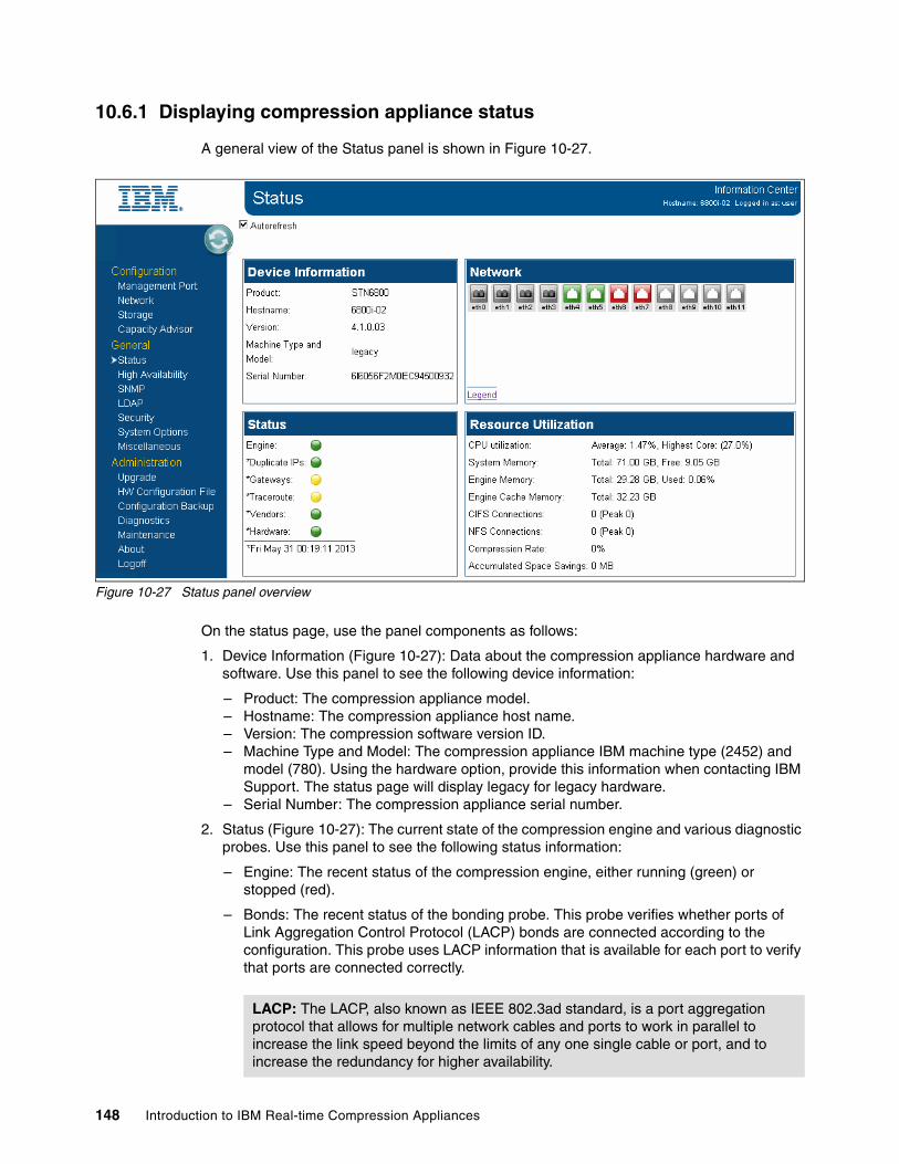
10.6.1 Displaying compression appliance status
A general view of the Status panel is shown in Figure 10-27.
Figure 10-27 Status panel overview
On the status page, use the panel components as follows:
1. Device Information (Figure 10-27): Data about the compression appliance hardware and software. Use this panel to see the following device information:
– Product: The compression appliance model.– Hostname: The compression appliance host name.– Version: The compression software version ID.– Machine Type and Model: The compression appliance IBM machine type (2452) and
model (780). Using the hardware option, provide this information when contacting IBM Support. The status page will display legacy for legacy hardware.
– Serial Number: The compression appliance serial number.
2. Status (Figure 10-27): The current state of the compression engine and various diagnostic probes. Use this panel to see the following status information:
– Engine: The recent status of the compression engine, either running (green) or stopped (red).
– Bonds: The recent status of the bonding probe. This probe verifies whether ports of Link Aggregation Control Protocol (LACP) bonds are connected according to the configuration. This probe uses LACP information that is available for each port to verify that ports are connected correctly.
LACP: The LACP, also known as IEEE 802.3ad standard, is a port aggregation protocol that allows for multiple network cables and ports to work in parallel to increase the link speed beyond the limits of any one single cable or port, and to increase the redundancy for higher availability.
148 Introduction to IBM Real-time Compression Appliances
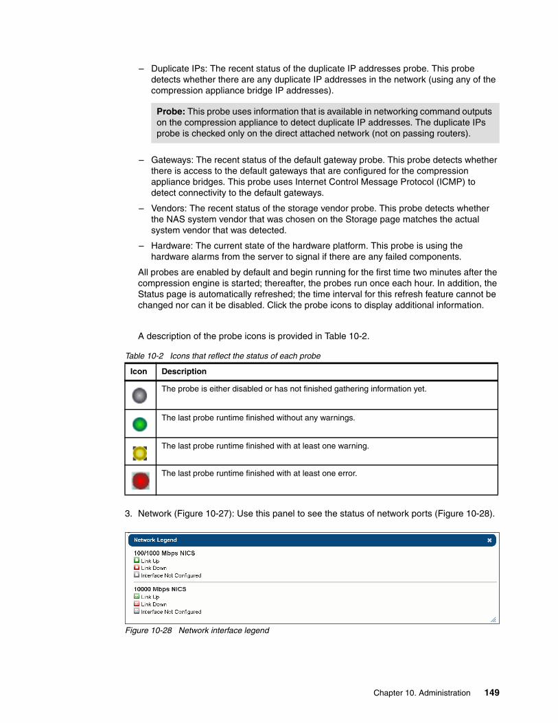
– Duplicate IPs: The recent status of the duplicate IP addresses probe. This probe detects whether there are any duplicate IP addresses in the network (using any of the compression appliance bridge IP addresses).
– Gateways: The recent status of the default gateway probe. This probe detects whether there is access to the default gateways that are configured for the compression appliance bridges. This probe uses Internet Control Message Protocol (ICMP) to detect connectivity to the default gateways.
– Vendors: The recent status of the storage vendor probe. This probe detects whether the NAS system vendor that was chosen on the Storage page matches the actual system vendor that was detected.
– Hardware: The current state of the hardware platform. This probe is using the hardware alarms from the server to signal if there are any failed components.
All probes are enabled by default and begin running for the first time two minutes after the compression engine is started; thereafter, the probes run once each hour. In addition, the Status page is automatically refreshed; the time interval for this refresh feature cannot be changed nor can it be disabled. Click the probe icons to display additional information.
A description of the probe icons is provided in Table 10-2.
Table 10-2 Icons that reflect the status of each probe
3. Network (Figure 10-27): Use this panel to see the status of network ports (Figure 10-28).
Figure 10-28 Network interface legend
Probe: This probe uses information that is available in networking command outputs on the compression appliance to detect duplicate IP addresses. The duplicate IPs probe is checked only on the direct attached network (not on passing routers).
Icon Description
The probe is either disabled or has not finished gathering information yet.
The last probe runtime finished without any warnings.
The last probe runtime finished with at least one warning.
The last probe runtime finished with at least one error.
Chapter 10. Administration 149

The following interface status information is displayed:
– Interface Up: The interface is configured and the physical link is up - port green.
– Interface Down: The interface is configured and the physical link is down - port red.
– Not configured: The interface is not configured; the physical link state is unknown because the interface is shut down from the software - port grey.
4. Resource (Figure 10-27): Utilization Monitoring of various system resources and performance metrics. Use this panel to see the following resources:
– CPU: Current compression appliance CPU utilization.
– System Memory: Total amount of RAM that is installed in the appliance.
– Engine Memory: Amount of memory that is currently allocated to the compression engine.
– Engine Cache Memory: Amount of memory that is allocated for the compression appliance to read cache.
– CIFS Connections: Current and peak number of CIFS connections.
– NFS Connections: Current and peak number of NFS connections.
– Compression Rate: The percentage of capacity saved; as data passes through the compression engine and gets compressed, the compression rate is calculated by the amount of data that has been saved (during write operations) compared to the total amount of data that has passed through the compression appliance.
– Accumulated Space Savings: The accumulated amount of disk space that has been saved by the compression over the complete runtime of the compression appliance or since the time the space savings counter was reset.
5. From the CLI, use the following commands to monitor all previous parameters:
– Hostname (Example 10-9): Returns the name of your appliance. Also you can modify the name of the appliance with this command.
Example 10-9 Hostname command output
[email protected]> hostnameHostname: RtCA1
– Display (Example 10-10): With the “config” or “sensor” attribute will return most of the hardware, software and networking information. The values attributes for probing modules are: green value is 1 and for red value is 0. Example 10-10 is displaying only the output for the display config command.
Example 10-10 Display command output
[email protected]> display config
======================================== DNS =================================== =====DNS Enabled: noDNS Domain:DNS Search:
======================================== NTP =================================== =====There are no ntp servers defined======================================== SNMP ================================== ======SNMP Enabled Yes
150 Introduction to IBM Real-time Compression Appliances

syslocation Computer roomsyscontactRead Only Community publicLow Free Memory Trap Interval (secs) 1800Low Free Disk Space Trap Interval (secs) 1800Fan Failed Trap Interval (secs) 1800Power Supply Failed Trap Interval (secs) 1800High Temperature Trap Interval (secs) 1800Disk Failed Trap Interval (secs) 60
Trap Destination Trap Port (Default 162) Trap Community127.0.0.1 - public
======================================== SYSLOG ================================ ========Send messages: yesSend changelog: yesSend sw_hw_snmp: yes======================================== LDAP ================================== ======LDAP: Disableduri:base:LDAP Server Type: ActiveDirectorybinddn:bindpw: ******anonymous bind: noauthorization filter:
======================================== SERVERS =============================== =========Storage Storage If Name Storage Vendor Storage IP Mode No New Compression StatusStorage1 N5600_A N_series 9.155.90.14 Transparent - StandbyStorage2 N5600_B N_series 9.155.90.16 Compressed Off Standby
======================================== HA ==================================== ====Enable Auto Sync: YesEnable File Extension Sync: YesAppliance HA Name: RtCA1
IP Name AutoSync LastSyncDate Shared Servers 9.155.66.158 RtCA2 Yes Wed Nov 2 12:39:26 CET 2011 9.155.90.14,9.1 55.90.16
======================================== DNS =================================== =====DNS Enabled: noDNS Domain:DNS Search:
======================================== BONDS ================================= =======Bond Mode Interfacesbond0 802.3ad eth4 eth8bond1 802.3ad eth5 eth9
Chapter 10. Administration 151
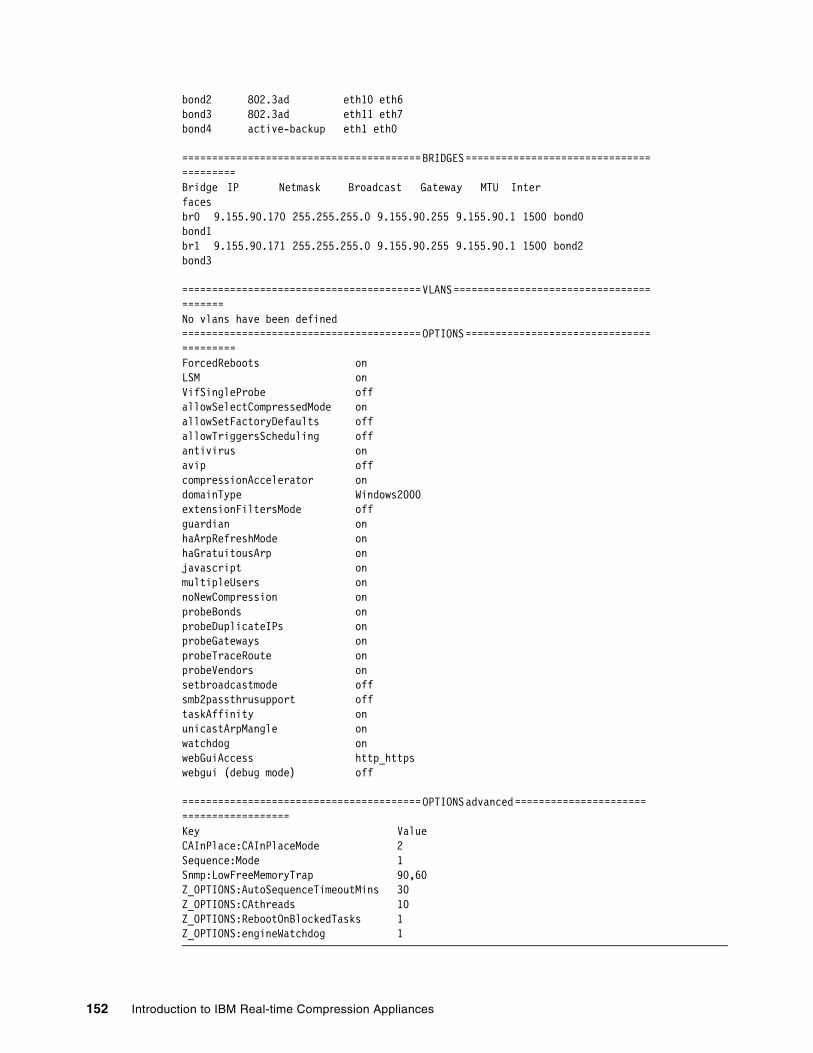
bond2 802.3ad eth10 eth6bond3 802.3ad eth11 eth7bond4 active-backup eth1 eth0
======================================== BRIDGES =============================== =========Bridge IP Netmask Broadcast Gateway MTU Inter facesbr0 9.155.90.170 255.255.255.0 9.155.90.255 9.155.90.1 1500 bond0 bond1br1 9.155.90.171 255.255.255.0 9.155.90.255 9.155.90.1 1500 bond2 bond3
======================================== VLANS ================================= =======No vlans have been defined======================================== OPTIONS =============================== =========ForcedReboots onLSM onVifSingleProbe offallowSelectCompressedMode onallowSetFactoryDefaults offallowTriggersScheduling offantivirus onavip offcompressionAccelerator ondomainType Windows2000extensionFiltersMode offguardian onhaArpRefreshMode onhaGratuitousArp onjavascript onmultipleUsers onnoNewCompression onprobeBonds onprobeDuplicateIPs onprobeGateways onprobeTraceRoute onprobeVendors onsetbroadcastmode offsmb2passthrusupport offtaskAffinity onunicastArpMangle onwatchdog onwebGuiAccess http_httpswebgui (debug mode) off
======================================== OPTIONS advanced ====================== ==================Key ValueCAInPlace:CAInPlaceMode 2Sequence:Mode 1Snmp:LowFreeMemoryTrap 90,60Z_OPTIONS:AutoSequenceTimeoutMins 30Z_OPTIONS:CAthreads 10Z_OPTIONS:RebootOnBlockedTasks 1Z_OPTIONS:engineWatchdog 1
152 Introduction to IBM Real-time Compression Appliances

– Engine (Example 10-11): Returns the status of the compression engine.
Example 10-11 Engine command output
[email protected]> engineEngine: running
– Partner (Example 10-12): Returns the state and configuration of the high availability feature.
Example 10-12 Partner command output
[email protected]> partnerEnable Auto Sync: YesEnable File Extension Sync: YesAppliance HA Name: RtCA1
IP Name AutoSync LastSyncDate Shared Servers9.155.66.158 RtCA2 Yes Wed Nov 2 12:39:26 CET 2011 9.155.90.14,9.155.90.16
10.6.2 Displaying storage status
To display the storage status, proceed as follows:
1. From the left panel, choose Storage to view the current status of your storage device. See Figure 10-29.
Figure 10-29 Monitor Storage status
Chapter 10. Administration 153

The Storage panel provides information about the connectivity status of each file server/storage.
There are three possible states for the Status parameter (Table 10-3).
Table 10-3 Storage icon status
2. To monitor the storage systems from the CLI, use the storage command as shown in Example 10-13. Here you can see the output of this command.
Example 10-13 Server command output
[email protected]> storageStorage Storage If Name Storage Vendor Storage IP Mode No New Compression StatusStorage1 N5600_A N_series 9.155.90.14 Transparent - StandbyStorage2 N5600_B N_series 9.155.90.16 Compressed off Standby
Icon Description
Not Connected: The compression appliance is unable to reach the file server.
Active: The compression appliance is connected in a high availability configuration and is currently the active appliance for this file server.
Standby: The compression appliance is connected in a high availability configuration and is currently the passive appliance for this file server.
Attention: The columns “Compression Mode” and “Compress New Files” are available for settings only if, from the “System Options,” you choose to enable them. The “Compression Mode” setting will automatically activate the “Compress New Files” option.
Tip: There can be several reasons why a file server is unreachable. For example, the server might be physically disconnected, the network switch port settings might be incorrect (wrong VLAN), and so on.
154 Introduction to IBM Real-time Compression Appliances

10.6.3 Displaying compression status
To list all compression filters configured and their status, proceed as follows:
1. Navigate to Diagnose from the navigation panel. Scroll down to the Compression Engine section, then click the Display Compression Filters link (Figure 10-30).
Figure 10-30 Compression filters status on diagnostics
This page displays information about the compression engine, including these items:
– Status: Lists the status of each of the CIFS shares and NFS exports that are defined on the Compression Filters page (Table 10-4).
Table 10-4 Storage icon status
Icon Description
A red status indicates that compression is not applied for the share or export. It also means an error - share does not exist.
A green status indicates that the share or exports exist and compression is applied for the shares or exports.
compress only selected shares/exports export mode (on NFS export).
Chapter 10. Administration 155
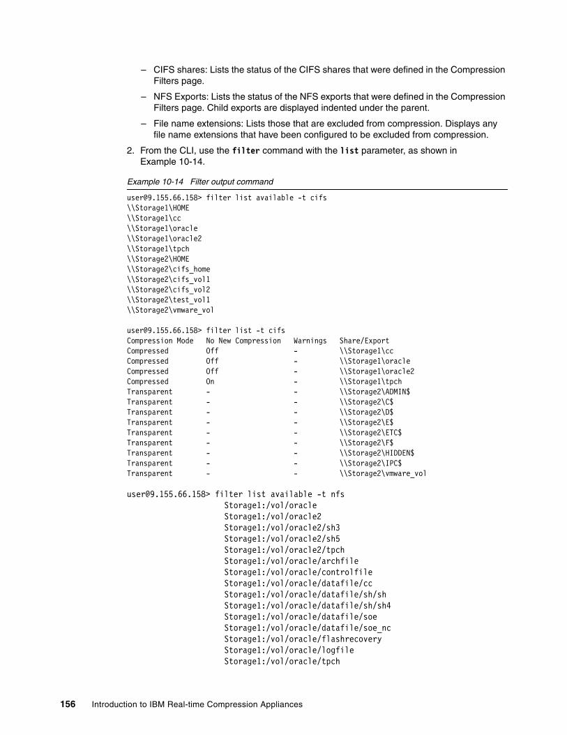
– CIFS shares: Lists the status of the CIFS shares that were defined in the Compression Filters page.
– NFS Exports: Lists the status of the NFS exports that were defined in the Compression Filters page. Child exports are displayed indented under the parent.
– File name extensions: Lists those that are excluded from compression. Displays any file name extensions that have been configured to be excluded from compression.
2. From the CLI, use the filter command with the list parameter, as shown in Example 10-14.
Example 10-14 Filter output command
[email protected]> filter list available -t cifs\\Storage1\HOME\\Storage1\cc\\Storage1\oracle\\Storage1\oracle2\\Storage1\tpch\\Storage2\HOME\\Storage2\cifs_home\\Storage2\cifs_vol1\\Storage2\cifs_vol2\\Storage2\test_vol1\\Storage2\vmware_vol
[email protected]> filter list -t cifsCompression Mode No New Compression Warnings Share/ExportCompressed Off - \\Storage1\ccCompressed Off - \\Storage1\oracleCompressed Off - \\Storage1\oracle2Compressed On - \\Storage1\tpchTransparent - - \\Storage2\ADMIN$Transparent - - \\Storage2\C$Transparent - - \\Storage2\D$Transparent - - \\Storage2\E$Transparent - - \\Storage2\ETC$Transparent - - \\Storage2\F$Transparent - - \\Storage2\HIDDEN$Transparent - - \\Storage2\IPC$Transparent - - \\Storage2\vmware_vol
[email protected]> filter list available -t nfs Storage1:/vol/oracle Storage1:/vol/oracle2 Storage1:/vol/oracle2/sh3 Storage1:/vol/oracle2/sh5 Storage1:/vol/oracle2/tpch Storage1:/vol/oracle/archfile Storage1:/vol/oracle/controlfile Storage1:/vol/oracle/datafile/cc Storage1:/vol/oracle/datafile/sh/sh Storage1:/vol/oracle/datafile/sh/sh4 Storage1:/vol/oracle/datafile/soe Storage1:/vol/oracle/datafile/soe_nc Storage1:/vol/oracle/flashrecovery Storage1:/vol/oracle/logfile Storage1:/vol/oracle/tpch
156 Introduction to IBM Real-time Compression Appliances

ACCESS_DENIED Storage1:/vol/vmiso Storage1:/vol/vmware Storage1:/vol/vmware1 Storage1:/vol/vol0 Storage1:/vol/vol0/home Storage2:/vol/cifs_homeACCESS_DENIED Storage2:/vol/cifs_vol1 Storage2:/vol/cifs_vol2 Storage2:/vol/iscsi_vol1 Storage2:/vol/nfs_vol1 Storage2:/vol/nfs_vol1/FreeBase Storage2:/vol/nfs_vol2ACCESS_DENIED Storage2:/vol/test_vol1ACCESS_DENIED Storage2:/vol/vmware Storage2:/vol/vmware_iscsi_ds Storage2:/vol/vmware_vol Storage2:/vol/vol0 Storage2:/vol/vol0/home
[email protected]> filter list -t nfsCompression Mode No New Compression Warnings Share/ExportCompressed Off - Storage1:/vol/oracle/datafile/ccCompressed Off - Storage1:/vol/oracle/datafile/sh/shCompressed Off - Storage1:/vol/oracle/datafile/sh/sh4Compressed Off - Storage1:/vol/oracle/datafile/soeCompressed Off - Storage1:/vol/oracle/flashrecoveryCompressed Off - Storage1:/vol/oracle/tpchCompressed Off - Storage1:/vol/oracle2/sh3Compressed Off - Storage1:/vol/vmwareCompressed Off - Storage1:/vol/vmware1Transparent - - Storage2:/vol/nfs_vol1/FreeBaseTransparent - - Storage2:/vol/vmware_vol
Chapter 10. Administration 157

10.7 Configuring SNMP
The health and performance of the Real-time Compression Appliance is monitored through the use of the SNMP protocol.
To configure the SNMP configuration settings, proceed as follows:
1. Go on the SNMP panel from navigation panel of the Web GUI, as shown in Figure 10-31.
.
Figure 10-31 SNMP Settings panel
2. From this panel, download MIB (Management Information Base) libraries as follows:
Choose Download from the top of the panel. These files are used within a monitoring management system. After importing the SNMP MIB libraries in your management server, you can move on and configure the SNMP protocol at the RTCA level. You need to configure the following parameters:
– SNMP: Select Enabled or Disabled to enable or disable the SNMP service.
– syslocation: The physical location of the compression appliance; for informative purposes only.
– syscontact: The name and contact details of the administrator or principal owner of the compression appliance; for informative purposes only.
– Read Only Community: The information group with read-only security access. The default community string is public.
– Low Free Memory Trap Interval: The interval (in seconds) between the “low free memory trap” alerts sent.
Important: Changing the community name as a first step in configuring SNMP is strongly advised against.
158 Introduction to IBM Real-time Compression Appliances
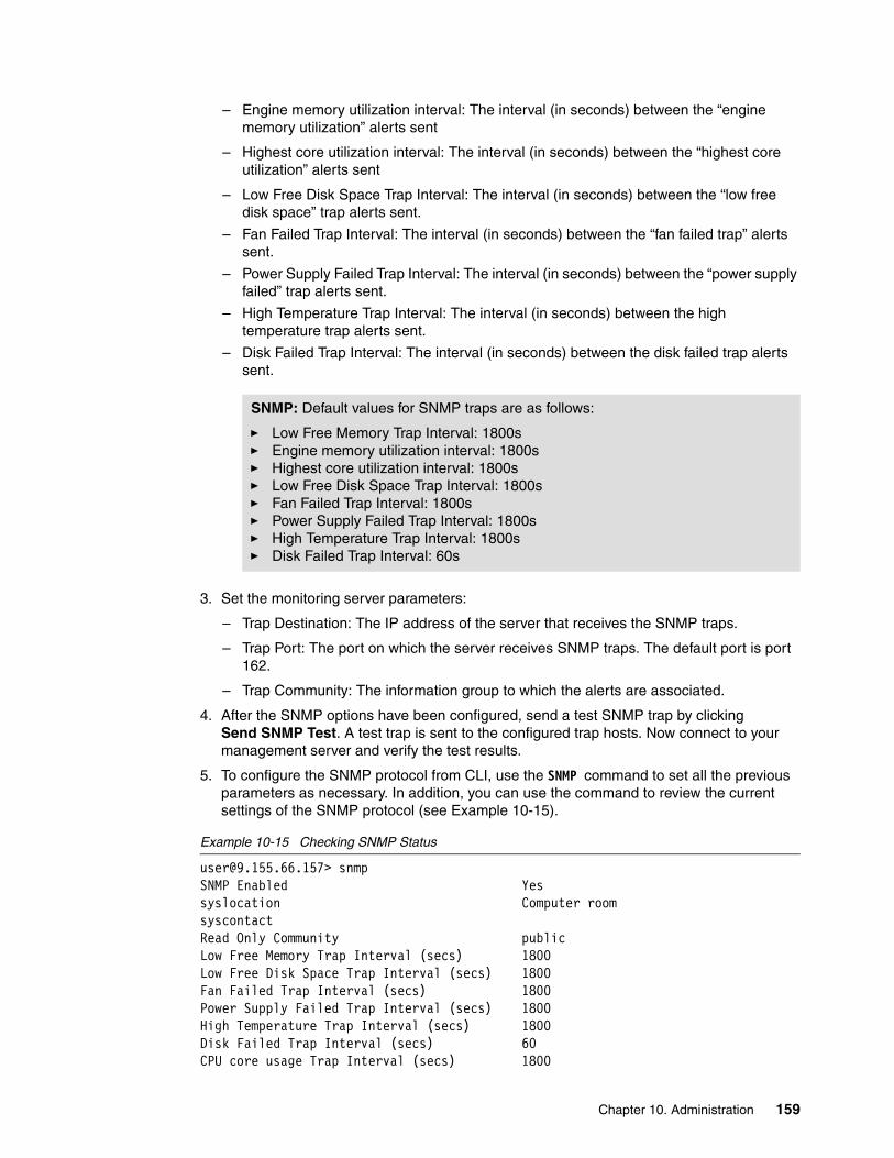
– Engine memory utilization interval: The interval (in seconds) between the “engine memory utilization” alerts sent
– Highest core utilization interval: The interval (in seconds) between the “highest core utilization” alerts sent
– Low Free Disk Space Trap Interval: The interval (in seconds) between the “low free disk space” trap alerts sent.
– Fan Failed Trap Interval: The interval (in seconds) between the “fan failed trap” alerts sent.
– Power Supply Failed Trap Interval: The interval (in seconds) between the “power supply failed” trap alerts sent.
– High Temperature Trap Interval: The interval (in seconds) between the high temperature trap alerts sent.
– Disk Failed Trap Interval: The interval (in seconds) between the disk failed trap alerts sent.
3. Set the monitoring server parameters:
– Trap Destination: The IP address of the server that receives the SNMP traps.
– Trap Port: The port on which the server receives SNMP traps. The default port is port 162.
– Trap Community: The information group to which the alerts are associated.
4. After the SNMP options have been configured, send a test SNMP trap by clicking Send SNMP Test. A test trap is sent to the configured trap hosts. Now connect to your management server and verify the test results.
5. To configure the SNMP protocol from CLI, use the SNMP command to set all the previous parameters as necessary. In addition, you can use the command to review the current settings of the SNMP protocol (see Example 10-15).
Example 10-15 Checking SNMP Status
[email protected]> snmpSNMP Enabled Yessyslocation Computer roomsyscontactRead Only Community publicLow Free Memory Trap Interval (secs) 1800Low Free Disk Space Trap Interval (secs) 1800Fan Failed Trap Interval (secs) 1800Power Supply Failed Trap Interval (secs) 1800High Temperature Trap Interval (secs) 1800Disk Failed Trap Interval (secs) 60CPU core usage Trap Interval (secs) 1800
SNMP: Default values for SNMP traps are as follows:
� Low Free Memory Trap Interval: 1800s� Engine memory utilization interval: 1800s� Highest core utilization interval: 1800s� Low Free Disk Space Trap Interval: 1800s� Fan Failed Trap Interval: 1800s� Power Supply Failed Trap Interval: 1800s� High Temperature Trap Interval: 1800s� Disk Failed Trap Interval: 60s
Chapter 10. Administration 159

Engine mem util. Trap Interval (secs) 1800
Trap Destination Trap Port (Default 162) Trap Community127.0.0.1 - public
Example 10-16 shows how to configure SNMP step by step using the CLI interface. Also, for an extensive help, you can use the SNMP help command.
Example 10-16 Configure SNMP using CLI
//enable SNMP on RtCA [email protected]> snmp enable
//download the MIB file to a workstation - the download is not supported in interactive SSH mode.bash> ssh [email protected] snmp mibs download > MIB_file.zip
//add an SNMP trap receiver to the system - management [email protected]> snmp trap add -i 9.155.66.190 -c public
//define the System Location in the [email protected]> snmp -l RightHere
//Define the interval between sending fan failure traps to 10 s. [email protected]> snmp -f 10
//test by sending a SNMP trap. [email protected]> snmp test
10.8 Configuring LDAP
The LDAP (Lightweight Directory Access Protocol) option can be used to configure the compression appliance to authorize administration users to log in to the web interface and CLI. The accounts that are configured in an LDAP directory service (that is, Active Directory) can be utilized in this way to log on and administrate the appliance.
10.8.1 Configure
In order to configure the LDAP protocol, proceed as follows:
1. Go on the navigation panel and click the LDAP option under the “General” section. The new panel will give you the possibility to choose and configure different LDAP parameters (Figure 10-32). The following parameters are available for configuration:
– LDAP: Choose whether LDAP authorization service is enabled or disabled. LDAP is disabled by default.
– type: The LDAP server type. Currently, only Microsoft Active Directory (Windows 2003/2008 - based) is supported.
Important: The LDAP option is used only for administrative connection purposes. It is not used for shares security or any other communication between the storage and the users.
160 Introduction to IBM Real-time Compression Appliances

– basedn: The LDAP directory base distinguished name (DN). Typically, the base DN is in the format DC=privatedomain, DC=com, where privatedomain.com is the Active Directory fully-qualified domain name (FQDN).
– Anonymous bind: Choose if configuring anonymous LDAP bind requests. The compression appliance attempts to bind to the LDAP server without specifying any credentials.
– binddn: Configure the bind domain name with a user name from the LDAP directory to send login-based LDAP bind requests. In most cases, any user in the LDAP tree can be used. LDAP searches do not usually require unique permissions. Use the following format:
CN=Administrator, OU=Users, DC=privatedomain, DC=com
– bindpw: Enter the password of the user name specified in the bind DN.
– Authorization filter: After configuring the LDAP, by default, all users in the base directory are allowed access to the compression appliance. If a restriction is imposed, you can limit the users allowed to log on by limiting the search of the RTCA in the LDAP data base. In order to limit the compression appliance access to a specific section of the LDAP directory, configure the authorization filter. A user is usually added to a group and the authorization filter is specified as a full FQDN (Example 10-17),
Example 10-17 Authorization filter setting example
memberOf=CN=STNUsers,DC=privatedomain,DC=com.
Figure 10-32 LDAP configuration
2. After configuring the LDAP protocol, as the next step, add LDAP servers. To do that, fill in the options from the bottom of the “LDAP” panel (Figure 10-33) with the name of the server and the IP address. If you are using more than one server for authentication, you can choose to give priority to the LDAP Server.
Tip: Selecting the Anonymous bind option causes the “binddn” and “bindpw” fields to disappear. The default Active Directory security policy does not accept anonymous binds. However, Active Directory can be configured to accept anonymous binds.
Chapter 10. Administration 161
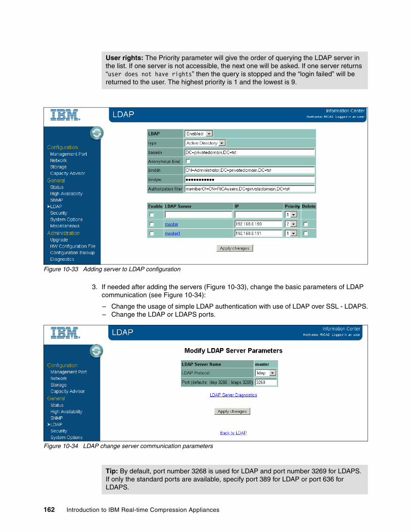
Figure 10-33 Adding server to LDAP configuration
3. If needed after adding the servers (Figure 10-33), change the basic parameters of LDAP communication (see Figure 10-34):
– Change the usage of simple LDAP authentication with use of LDAP over SSL - LDAPS.– Change the LDAP or LDAPS ports.
Figure 10-34 LDAP change server communication parameters
User rights: The Priority parameter will give the order of querying the LDAP server in the list. If one server is not accessible, the next one will be asked. If one server returns “user does not have rights” then the query is stopped and the “login failed” will be returned to the user. The highest priority is 1 and the lowest is 9.
Tip: By default, port number 3268 is used for LDAP and port number 3269 for LDAPS. If only the standard ports are available, specify port 389 for LDAP or port 636 for LDAPS.
162 Introduction to IBM Real-time Compression Appliances

4. To configure LDAP protocol and servers using the CLI, follow Example 10-18.
Example 10-18 Configuring LDAP using CLI
//check LDAP [email protected]> ldapLDAP: Disableduri:base: LDAP Server Type:binddn: bindpw: ******anonymous bind: noauthorization filter:
//set LDAP [email protected]> ldap set type ActiveDirectoryLDAP type set to Active Directory
//set base [email protected]> ldap set base DC=privatedomain,DC=tstLDAP basedn set
//set anonymous [email protected]> ldap set no_anonymous_bindNo anonymous bind set
//Set the user used to bind [email protected]> ldap set binddn CN=Admin,OU=RtCA,CN=privatedomain,CN=tst
//set password for user accesing the [email protected]> ldap set bindpw a1b2c3
//Restrict the groups that should be search to approve log [email protected]> ldap set filter memberOf=CN=RtCA,DC=privatedomain,DC=tstLDAP filter set
//Enable and check the [email protected]> ldap enableLDAP [email protected]> ldapLDAP: Enableduri:base: DC=privatedomain,DC=tstLDAP Server Type: ActiveDirectorybinddn: CN=Admin,OU=RtCA,CN=privatedomain,CN=tstbindpw: ******anonymous bind: noauthorization filter: memberOf=CN=RtCA,DC=privatedomain,DC=tst
//add server - prior to add a server you should check the DNS configuration - it must be disabled
[email protected]> dnsDNS Enabled: yesDNS Domain: privatedomain.tstDNS Search: privatedomain.tst
Chapter 10. Administration 163

DNS server 192.168.0.190: down
[email protected]> dns disableDNS Disabled
[email protected]>ldap server add ldap1 -protocol ldap -ip 192.168.0.190 -port 3268 -priority 1Added new ldap server
[email protected]> dns enableDNS Enabled
[email protected]> ldapLDAP: Enableduri:base: DC=privatedomain,DC=tstLDAP Server Type: ActiveDirectorybinddn: CN=Admin,OU=RtCA,CN=privatedomain,CN=tstbindpw: ******anonymous bind: noauthorization filter: memberOf=CN=RtCA,DC=privatedomain,DC=tst
LDAP Server: ldap1 Enabled: yes Priority: 1 State: ActiveLDAP Server: ldap2 Enabled: yes Priority: 2 State: Active
10.8.2 Diagnose
To diagnose a potential problem on the LDAP communication, proceed as follows:
1. Use the “LDAP server diagnostics” panel accessible from the LDAP server parameters panel (Figure 10-34 on page 162). The new panel will give you access to the available tools to diagnose your LDAP configuration (see Figure 10-35).
Figure 10-35 LDAP diagnose page
164 Introduction to IBM Real-time Compression Appliances
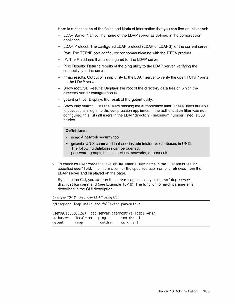
Here is a description of the fields and kinds of information that you can find on this panel:
– LDAP Server Name: The name of the LDAP server as defined in the compression appliance.
– LDAP Protocol: The configured LDAP protocol (LDAP or LDAPS) for the current server.
– Port: The TCP/IP port configured for communicating with the RTCA product.
– IP: The P address that is configured for the LDAP server.
– Ping Results: Returns results of the ping utility to the LDAP server, verifying the connectivity to the server.
– nmap results: Output of nmap utility to the LDAP server to verify the open TCP/IP ports on the LDAP server.
– Show rootDSE Results: Displays the root of the directory data tree on which the directory server configuration is.
– getent entries: Displays the result of the getent utility.
– Show ldap search: Lists the users passing the authorization filter. These users are able to successfully log in to the compression appliance. If the authorization filter was not configured, this lists all users in the LDAP directory - maximum number listed is 200 entries.
2. To check for user credential availability, enter a user name in the “Get attributes for specified user” field. The information for the specified user name is retrieved from the LDAP server and displayed on the page.
By using the CLI, you can run the server diagnostics by using the ldap server diagnostics command (see Example 10-19). The function for each parameter is described in the GUI description.
Example 10-19 Diagnose LDAP using CLI
//Diagnose ldap using the following parameters
[email protected]> ldap server diagnostics ldap1 -diagauthusers localcert ping rootdsesslgetent nmap rootdse sslclient
Definitions:
� nmap: A network security tool.
� getent: UNIX command that queries administrative databases in UNIX. The following databases can be queried: password, groups, hosts, services, networks, or protocols.
Chapter 10. Administration 165

10.9 Miscellaneous tasks
For changing parameters that do not fit into previous categories, select the Miscellaneous page and choose the appropriate link for your task (see Figure 10-36).
Figure 10-36 Miscellaneous settings page
10.9.1 Date and time settings
In order to change the date and time settings, choose the Date and Time Configuration option from the Miscellaneous panel (Figure 10-36). In the new panel, you can change the date and time and also configure the NTP servers (see Figure 10-37).
166 Introduction to IBM Real-time Compression Appliances

Figure 10-37 Setting Date and Time
Changes to Date and Time settings will require restarting the compression engine. See Figure 10-38.
Figure 10-38 Restarting engine for setting Date and Time
To set up from the CLI, you can use the date, nt, and timezone commands (Example 10-20).
Example 10-20 Setting date and time parameters
[email protected]> date -d 2011-11-02 -t 16:59//engine will restarted automatically
[email protected]> dateThu Apr 14 16:59:41 CEST 2011
//set and check the ntp [email protected]> ntpThere are no ntp servers [email protected]> ntp add [email protected]> ntpServer: 192.168.0.190
Chapter 10. Administration 167
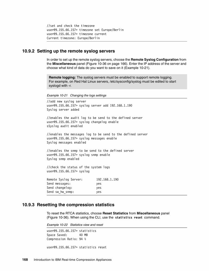
//set and check the [email protected]> timezone set Europe/[email protected]> timezone currentCurrent timezone: Europe/Berlin
10.9.2 Setting up the remote syslog servers
In order to set up the remote syslog servers, choose the Remote Syslog Configuration from the Miscellaneous panel (Figure 10-36 on page 166). Enter the IP address of the server and choose what kind of data do you want to save on it (Example 10-21).
Example 10-21 Changing the logs settings
//add new syslog [email protected]> syslog server add 192.168.1.190Syslog server added
//enables the audit log to be send to the defined [email protected]> syslog changelog enablesSyslog audit enabled
//enables the messages log to be send to the defined [email protected]> syslog messages enableSyslog messages enabled
//enables the snmp to be send to the defined [email protected]> syslog snmp enableSyslog snmp enabled
//check the status of the system [email protected]> syslog
Remote Syslog Server: 192.168.1.190Send messages: yesSend changelog: yesSend sw_hw_snmp: yes
10.9.3 Resetting the compression statistics
To reset the RTCA statistics, choose Reset Statistics from Miscellaneous panel (Figure 10-36). When using the CLI, use the statistics reset command.
Example 10-22 Statistics view and reset
[email protected]> statisticsSpace Saved: 40 MBCompression Ratio: 94 %
[email protected]> statistics reset
Remote logging: The syslog servers must be enabled to support remote logging. For example, on Red Hat Linux servers, /etc/sysconfig/syslog must be edited to start syslogd with -r.
168 Introduction to IBM Real-time Compression Appliances

Statistics reset successfully
[email protected]> statisticsSpace Saved: 0 MBCompression Ratio: 0 %[email protected]>
10.9.4 Web interface session timeout
To change the web interface timeout value, go to the Miscellaneous panel, Session Timeout field, and change the value (Figure 10-36).
10.9.5 DNS server setup
When you are using DNS servers, select the DNS Configuration option from the Miscellaneous panel (Figure 10-36 on page 166).
To execute the previous tasks using the CLI, use the dns command as shown in Example 10-23.
Example 10-23 Changing DNS settings
//verify DNS [email protected]> dnsDNS Enabled: noDNS Domain:DNS Search:
//set domain [email protected]> dns domain set privatedomain.tstSet DNS Domain privatedomain.tst
//set IP adress for DNS lookup [email protected]> dns server add 192.168.0.190Added DNS Nameserver 192.168.0.190
//set the search DNS domain [email protected]> dns search set privatedomain.tstSet DNS Search privatedomain.tst
//check dns [email protected]> dnsDNS Enabled: noDNS Domain: privatedomain.tstDNS Search: privatedomain.tstDNS server 192.168.0.190: up
//enable [email protected]> dns enableDNS Enabled
Tip: When the DNS is configured, you can use DNS host names when you configure the SMTP, NTP, LDAP, and syslog servers.
Chapter 10. Administration 169
10.10 Maintaining the compression appliances
This section focuses on maintenance tasks for the RTCA.
10.10.1 Reboot and shutdown
The RTCA must remain operational at all times to maintain access to the NAS storage server. Only perform a restart or shutdown in exceptional cases, such as for planned downtime.
On the Maintenance page, you can find the two options Reboot and Shutdown (Figure 10-39).
Figure 10-39 Reboot and Shutdown
To execute the reboot or the shutdown task, you need to enter the password of the user who is currently logged in. Optionally, you are able to enter a textual note regarding the reason for the reboot or shutdown. This text appears in the audit log.
10.10.2 Backing up and restoring the configuration settings
You need to back up the RTCA configuration for recovery purposes and before doing any system upgrade. The configuration backup option enables you to export the configuration settings to an external file, restore configuration settings from an external file previously saved, and restore factory default configuration settings (optional). To open the input area, click the Configuration Backup option in the menu as shown in Figure 10-40.
Important: It is best to stop the compression engine before shutting down the system. To stop the compression engine, click Stop Engine in the Network page.
170 Introduction to IBM Real-time Compression Appliances
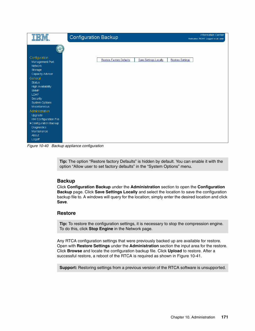
Figure 10-40 Backup appliance configuration
BackupClick Configuration Backup under the Administration section to open the Configuration Backup page. Click Save Settings Locally and select the location to save the configuration backup file to. A windows will query for the location; simply enter the desired location and click Save.
Restore
Any RTCA configuration settings that were previously backed up are available for restore. Open with Restore Settings under the Administration section the input area for the restore. Click Browse and locate the configuration backup file. Click Upload to restore. After a successful restore, a reboot of the RTCA is required as shown in Figure 10-41.
Tip: The option “Restore factory Defaults” is hidden by default. You can enable it with the option “Allow user to set factory defaults” in the “System Options” menu.
Tip: To restore the configuration settings, it is necessary to stop the compression engine. To do this, click Stop Engine in the Network page.
Support: Restoring settings from a previous version of the RTCA software is unsupported.
Chapter 10. Administration 171

Figure 10-41 Restore of the configuration
Restore factory defaults
Click Configuration Backup under the Administration section to open the Restore Factory defaults page. To execute this task, you need to enter the password of the user who is currently logged in and click Accept as shown in Figure 10-42.
Figure 10-42 Maintenance: restore factory defaults
Tip: To restore factory defaults, is necessary to stop the compression engine. To do this, click Stop Engine in the Network page.
172 Introduction to IBM Real-time Compression Appliances

10.11 Configuring system options
To modify general options for the IBM RTCA product, go on the System Options panel. It can be found on the left in your GUI as shown in Figure 10-43.
Figure 10-43 System Options
The following options are accessible:
� WebGui: The default setting is normal mode. If you change to debug mode, additional debug information is displayed at the top of each page.
� JavaScript: Choose Enable or Disable to activate or stop the use of JavaScript in the web interface pages. JavaScript is mainly used for pop-ups when you use the web interface. The default setting is enabled.
� Network Traffic Capture line: This option shows the status of the tcpdump network capture. This line only displays the status of the tcpdump option; to activate tcpdump, select Diagnostics panel Run tcpdump.
Chapter 10. Administration 173
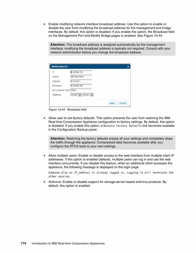
� Enable modifying network interface broadcast address: Use this option to enable or disable the user from modifying the broadcast address for the management and bridge interfaces. By default, this option is disabled. If you enable this option, the Broadcast field on the Management Port and Modify Bridge pages is enabled. See Figure 10-44.
Figure 10-44 Broadcast field
� Allow user to set factory defaults: This option prevents the user from restoring the IBM Real-time Compression Appliance configuration to factory settings. By default, this option is disabled. If you enable this option, a Restore Factory Defaults link becomes available in the Configuration Backup panel.
� Allow multiple users: Enable or disable access to the web interface from multiple client IP addresses. If this option is enabled (default), multiple users can log in and use the web interface concurrently. If you disable this feature, when an additional client accesses the appliance, the following message is displayed on the login page:
Someone else on IP_address is already logged in. Logging in will terminate the other session.
� Antivirus: Enable or disable support for storage-server-based antivirus products. By default, this option is enabled.
Attention: The broadcast address is assigned automatically by the management interface; modifying the broadcast address is typically not required. Consult with your network administrator before you change the broadcast address.
Attention: Restoring the factory defaults erases all your settings and completely stops the traffic through the appliance. Compressed data becomes available after you configure the RTCA back to your own settings.
174 Introduction to IBM Real-time Compression Appliances

� Antivirus server IPs: Enable or disable support for specific McAfee virus scanning products. By default, support is disabled. If this option is enabled, a new Antivirus Server IP column is displayed in the Storage panel. See Figure 10-45.
Figure 10-45 System Options - Change Antivirus Server IPs
� Watchdog: Enable or disable the hardware watchdog feature. By default, this option is enabled.
� Guardian: Enable or disable the guardian process that automatically recovers from engine failures. By default, this option is enabled.
� CA Full Scan: Enable or disable the Compression Accelerator feature from the Storage panel that enables the user to compress existing data. By default, this option is enabled. If you disable this feature, the result might be that a volume will have both compressed and uncompressed data. Do not disable this feature unless instructed by IBM Support.
� LSM: Enable or disable the link status mirroring (LSM) feature. By default, this feature is enabled. Do not disable this feature unless instructed by IBM Support.
� Web GUI Access: Enable or disable the protocol used for GUI management. The HTTP-only mode allows only standard HTTP (port 80) access to the web interface; HTTPS-only allows only secured HTTP (port 443) access to the web interface. HTTP or HTTPs (the default) accepts either.
� Task Affinity: Enable or disable the automatic tuning of CPU affinity. By default, this feature is enabled for highest performance as internal modules of the compression appliance are balanced across the CPU cores using optimal CPU affinity. Do not disable this feature unless instructed by IBM Support.
Guardian and Watchdog difference: Although Guardian and Watchdog features can both operate with traffic interruption, the difference between them is as follows:
� Guardian can restart the process based on ID only when and if that process hangs.� Watchdog issues a complete restart and initialization of the hardware machine.
Because both processes are disruptive, do not disable them unless instructed by IBM Support.
Tip: The web interface supports HTTP and HTTPS. To configure HTTPS certificates, use the same procedure described in “Setting Up SSH authentication” in IBM Real-time Compression Appliances CLI Command Reference Version 4 Release 1, GA32-2219-01.
Chapter 10. Administration 175

� HA gratuitous ARP: Enable or disable support for passing gratuitous ARP messages. By default, this feature is enabled. Do not disable this feature unless instructed by IBM Support.
� HA ARP mode refresh: Enable or disable support for high availability environments. By default, this feature is enabled. Do not disable this feature unless instructed by IBM Support.
� Extension Filters Mode: Choose Include or Exclude to configure the mode in which the extension filters are applied. By default, the extension filters that are configured and listed at the bottom of the Compression Filters panel define which extensions are excluded from compression (this is the Exclude mode). If Include is configured, the appliance compresses only files with extensions that are defined in the list.
� Unicast ARP Mangle: Enable or disable support for passing unicast ARP messages. By default, this feature is enabled. Do not disable this feature unless instructed by IBM Support.
� Vif Single Probe: Enable or disable support for Data ONTAP single VIF configurations. By default, this feature is disabled. Do not enable this feature unless instructed by IBM Support.
� User Autosupport Scheduling: Allow or prevent the user from modifying the default schedule for Autosupport reports. By default, this feature is enabled.
� Forced reboots: Enable or disable the forced reboots after frequent engine restarts. This option is applicable only for high availability configurations (in single appliance configurations, frequent engine warm restarts eventually become cold restarts; in high availability configurations, the warm restarts become forced reboots if the partner appliance and also its engine are running). By default, this option is enabled.
� SMB2 Pass Thru Support: Enable or disable the support for SMBv2-based CIFS sessions. By default, this option is disabled; CIFS sessions from SMBv2-enabled clients (such as Windows Vista, Windows 7, or Windows Server 2008) are downgraded automatically to SMBv1 protocol.
� Compress New Files: This setting does not change the behavior of the storage system compression mode, which pertains strictly to how new files are created. Use the Compress new files mode in cases where it is important to preserve the system maintenance operations and the current state of shares. For example, a storage system IP address is configured as Compress shares/exports except selected in its Compression Mode field, and the storage administrator wants to create a share that must work in uncompressed mode, so a compression filter is created after the share is created on the storage.
� Compressed mode: This feature changes the default behavior of RTCA when new storage is added.
From the CLI, use the options command followed by the appropriate option and either the on or off parameter to enable or disable that feature as presented Example 10-24.
Values 0 and 1: A value of 0 (zero) is associated with the off option; a value of 1 is assimilated with the on option.
176 Introduction to IBM Real-time Compression Appliances

Example 10-24 Check “System Options” status
[email protected]> optionCA_FullScan 1ForcedReboots 1LSM 1VifSingleProbe 0allowSelectCompressedMode 1allowSetFactoryDefaults 1allowTriggersScheduling 0antivirus 1avip 0extensionFiltersMode excludeguardian 1haArpRefreshMode 1haGratuitousArp 1javascript 1multipleUsers 1noNewCompression 1probeBonds 1probeDuplicateIPs 1probeGateways 1probeVendors 1setbroadcastmode 0smb2passthrusupport 0taskAffinity 1unicastArpMangle 1watchdog 1webGuiAccess http_httpswebgui (debug mode) 0
To list all options, type the word option and then press the Tab key. This step can help you identify the correct parameter. See Example 10-25.
Example 10-25 List options
[email protected]> optionCA_FullScan allowSetFactoryDefaults guardiannoNewCompression setbroadcastmode webGuiAccessForcedReboots allowTriggersScheduling haArpRefreshModeprobeBonds smb2passthrusupport webguiLSM antivirus haGratuitousArpprobeDuplicateIPs taskAffinityVifSingleProbe avip javascriptprobeGateways unicastArpMangleallowSelectCompressedMode extensionFiltersMode multipleUsers
Example 10-26 shows changing a parameter.
Example 10-26 Change a parameter
[email protected]> option allowSetFactoryDefaults off
Chapter 10. Administration 177

10.12 Diagnosing problems
Before contacting IBM Support, trigger a new Autosupport. To do so, click Diagnostics, next click Configure Autosupport, and then click Sent Test Email. If there is any problem with Autosupport or if requested by IBM Support, collect a diagnostics package by clicking Diagnostics, followed by clicking Collect Customer Support Diagnostics, and upload the attachment to IBM as instructed by IBM Support.
For more information, see the IBM Real-time Compression Appliance Troubleshooting Guide.
10.13 Recovering files when appliance is unavailable
The compression appliance transparently and automatically compresses and decompresses data in real-time.
If the compression appliance is unavailable for any reason, the IBM Real-time Compression Appliance data recovery utility can recover files or directories that were previously compressed by the compression appliance. For example, when you send files to a remote site over a WAN, you can send the files in compressed form to save time and bandwidth usage.
If the remote site does not have a compression appliance installed, the IBM Real-time Compression Appliance data recovery utility can decompress the files at the remote site in place of the compression appliance. IBM Real-time Compression Appliance data recovery utility can be used only on a workstation or server that is directly connected to the storage device (that is, not connected through the compression appliance). If the workstation or server is connected through the compression appliance, the compression appliance recompresses the files. The recovery utility is available as a GUI based as well as a CLI tool.
You can download this tool from the following website:
http://www.ibm.com/storage/support/rtc
10.13.1 Using the data recovery utility
You can define up to 99 tasks that control which files are processed and how they are processed. You can configure options to determine processing speed, error handling, and the messages log. After you configure the options and create, edit, or delete tasks to determine which files are decompressed, you can then run the tasks.
IBM Real-time Compression Appliance data recovery utility options apply to all defined tasks and can be modified only when tasks are not running. For information about determining whether tasks are running or about stopping tasks, see “Running the data recovery utility.”
Attention: You need to configure options immediately after IBM Real-time Compression Appliance data recovery utility installation.
178 Introduction to IBM Real-time Compression Appliances

10.13.2 Running the data recovery utility
To perform a recovery, proceed as follows:
1. If the data recovery utility is not running, select the IBM Real-time Compression Appliance data recovery utility from the appropriate Start menu folder (for example, Start Programs IBM Real-time Compression Appliance data recovery utility Real-time Compression Appliance data recovery utility) or from the default installation directory:
C:\Program Files\IBM\Real-time Compression Appliance data recovery utility\revert.exe
In the Linux environment, go to the recovery utility directory and run ./revert on an X session.
The data recovery utility opens and by default, displays the Task List tab (Figure 10-46).
Figure 10-46 Recovery utility
Chapter 10. Administration 179

2. Select Options and Configuration from the menu. The Configuration window opens (see Figure 10-47).
Figure 10-47 RTCA recovery utility - edit task parameters
180 Introduction to IBM Real-time Compression Appliances

3. Select the appropriate options according to the information (see Table 10-5).
Table 10-5 Configuration panel options
Option Description
Number of Threads The number of concurrent threads running on the client. Configuring multiple threads increases processing speed by enabling multiple files to be processed simultaneously. For example, if the Number of Threads value is set to 4, four files are processed at the same time.Valid values are in the range 1-10.
Note: The number in the center of the scroll bar represents the selected number of threads.
Errors Threshold Select the number of errors that must be exceeded in a task to perform the action specified in the then field.Valid values are in the range 1-300.
Note: The number in the center of the scroll bar represents the selected number of errors.
Threshold Behavior The action issued when the predetermined number of errors is encountered. The options are:
Next Task: Go to the next task. The status of the current task is Aborted.
Abort: Stop performing tasks. The status of the current task is Aborted.Continue: Continue with the current task.
Clear All Messages Clears all the messages from the Message Log tab (optional).
Log File Name The location of the message log file (this field is read-only).
Chapter 10. Administration 181

10.13.3 Creating data-recovery tasks
The data recovery utility tasks specify which files are to be decompressed as well as the order in which they are decompressed. Creating tasks includes defining source and destination directories (which files are decompressed and where they are saved), priorities (the order in which the tasks are run), and additional task parameters.
You can create up to nine tasks. Because finished or aborted tasks are not deleted automatically, you can delete them to create additional tasks, if necessary. Default settings are applied to new tasks. To customize the new task default settings, configure a task's parameters and click Save As Defaults in the Edit Task Parameters dialog box. For example, if Copy Attributes is selected and Copy All Files is deselected in your customized default task parameters, these options remain selected or deselected when you create a new task.
To create a new task, proceed as follows:
1. On the recovery utility, click the New button to configure task parameters (Figure 10-48).
Figure 10-48 Edit Task Parameter
182 Introduction to IBM Real-time Compression Appliances
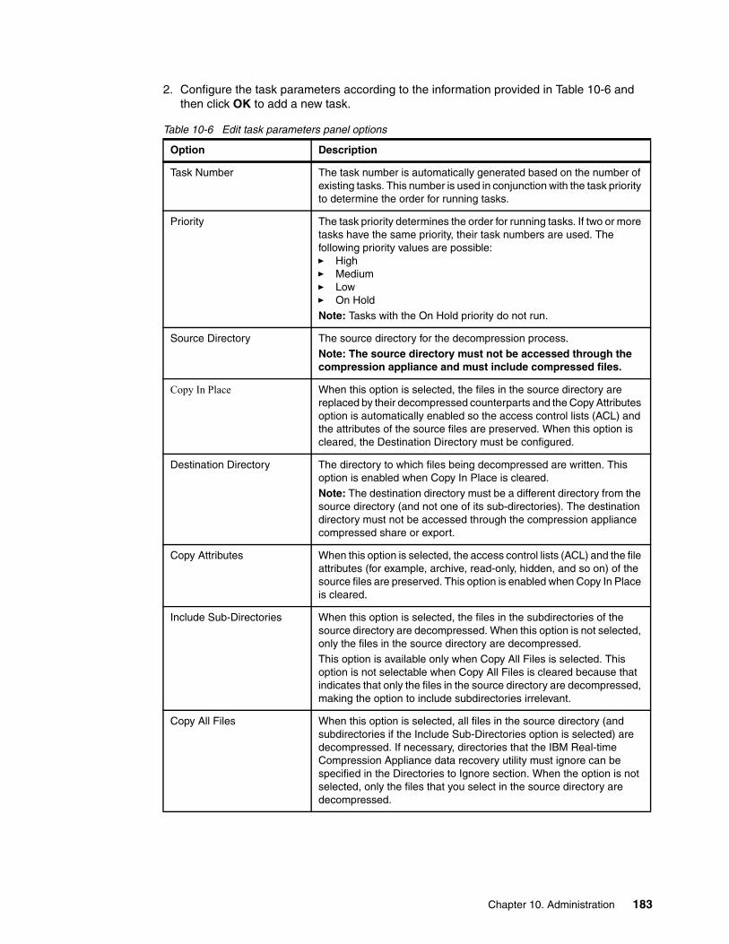
2. Configure the task parameters according to the information provided in Table 10-6 and then click OK to add a new task.
Table 10-6 Edit task parameters panel options
Option Description
Task Number The task number is automatically generated based on the number of existing tasks. This number is used in conjunction with the task priority to determine the order for running tasks.
Priority The task priority determines the order for running tasks. If two or more tasks have the same priority, their task numbers are used. The following priority values are possible:� High� Medium� Low� On Hold
Note: Tasks with the On Hold priority do not run.
Source Directory The source directory for the decompression process.
Note: The source directory must not be accessed through the compression appliance and must include compressed files.
Copy In Place When this option is selected, the files in the source directory are replaced by their decompressed counterparts and the Copy Attributes option is automatically enabled so the access control lists (ACL) and the attributes of the source files are preserved. When this option is cleared, the Destination Directory must be configured.
Destination Directory The directory to which files being decompressed are written. This option is enabled when Copy In Place is cleared.
Note: The destination directory must be a different directory from the source directory (and not one of its sub-directories). The destination directory must not be accessed through the compression appliance compressed share or export.
Copy Attributes When this option is selected, the access control lists (ACL) and the file attributes (for example, archive, read-only, hidden, and so on) of the source files are preserved. This option is enabled when Copy In Place is cleared.
Include Sub-Directories When this option is selected, the files in the subdirectories of the source directory are decompressed. When this option is not selected, only the files in the source directory are decompressed.
This option is available only when Copy All Files is selected. This option is not selectable when Copy All Files is cleared because that indicates that only the files in the source directory are decompressed, making the option to include subdirectories irrelevant.
Copy All Files When this option is selected, all files in the source directory (and subdirectories if the Include Sub-Directories option is selected) are decompressed. If necessary, directories that the IBM Real-time Compression Appliance data recovery utility must ignore can be specified in the Directories to Ignore section. When the option is not selected, only the files that you select in the source directory are decompressed.
Chapter 10. Administration 183

3. The new task item will be displayed on the Task List. See Figure 10-49.
Figure 10-49 Task List
Directories to Ignore—This section appears when Copy All Files is selected.
Directory The subdirectory of the source directory that is to be ignored when the task is processed. This is mainly used for various types of snapshot or backup directories, which usually have the same name. It is sufficient to specify only a directory name and not its path. Click Browse to select the directory or add it manually.
List of Directories to Ignore Lists the subdirectories of the source directory to ignore when the task is processed.Note: NetApp or N series snapshot directories are added by default.
Files to Copy—This section appears when Copy All Files is cleared.
List of Files to Copy Lists specific files from the source directory that are to be processed.
Option Description
184 Introduction to IBM Real-time Compression Appliances
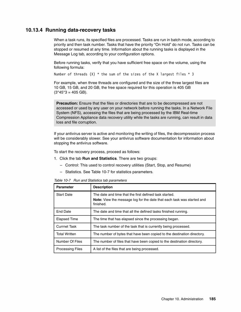
10.13.4 Running data-recovery tasks
When a task runs, its specified files are processed. Tasks are run in batch mode, according to priority and then task number. Tasks that have the priority “On Hold” do not run. Tasks can be stopped or resumed at any time. Information about the running tasks is displayed in the Message Log tab, according to your configuration options.
Before running tasks, verify that you have sufficient free space on the volume, using the following formula:
Number of threads (X) * the sum of the sizes of the X largest files * 3
For example, when three threads are configured and the size of the three largest files are 10 GB, 15 GB, and 20 GB, the free space required for this operation is 405 GB (3*45*3 = 405 GB).
If your antivirus server is active and monitoring the writing of files, the decompression process will be considerably slower. See your antivirus software documentation for information about stopping the antivirus software.
To start the recovery process, proceed as follows:
1. Click the tab Run and Statistics. There are two groups:
– Control: This used to control recovery utilities (Start, Stop, and Resume)
– Statistics. See Table 10-7 for statistics parameters.
Table 10-7 Run and Statistics tab parameters
Precaution: Ensure that the files or directories that are to be decompressed are not accessed or used by any user on your network before running the tasks. In a Network File System (NFS), accessing the files that are being processed by the IBM Real-time Compression Appliance data recovery utility while the tasks are running, can result in data loss and file corruption.
Parameter Description
Start Date The date and time that the first defined task started.
Note: View the message log for the date that each task was started and finished.
End Date The date and time that all the defined tasks finished running.
Elapsed Time The time that has elapsed since the processing began.
Currnet Task The task number of the task that is currently being processed.
Total Written The number of bytes that have been copied to the destination directory.
Number Of Files The number of files that have been copied to the destination directory.
Processing Files A list of the files that are being processed.
Chapter 10. Administration 185

2. Click Start. The IBM Real-time Compression Appliance data recovery utility begins processing the tasks (Figure 10-50). A dialog box notifies you when all tasks are complete.
Figure 10-50 Running data recovery utility
10.13.5 Viewing data-recovery logs
The Message Log tab displays a maximum of 300 messages. A complete list of messages is recorded in the data recovery utility log in the IBM Real-time Compression Appliance data recovery utility message log file.
You can use the log files to verify if your data recovery process has been performed successfully.
186 Introduction to IBM Real-time Compression Appliances

Part 3 Solution architectures
In this part of the book, we provide solution architectures for implementing the IBM Real-time Compression Appliance in several application environments. Based on these best practices, you will be able to implement the IBM Real-time compression with as little impact as possible.
Part 3
© Copyright IBM Corp. 2013. All rights reserved. 187

188 Introduction to IBM Real-time Compression Appliances
Chapter 11. NAS / N series solution design
In this chapter, we explain some common architectures and the corresponding configurations of virtual network interfaces. Furthermore, we discuss typical Network Attached Storage (NAS) and N series architectures in combination with IBM Real-time Compression Appliance (RTCA) solutions.
11
Important: This chapter uses IBM System Storage N series as NAS systems. The different solution and design approaches can be easily applied to other NAS solutions available in the marketplace.
© Copyright IBM Corp. 2013. All rights reserved. 189

11.1 Introduction to the design examples
Figure 11-1 and Figure 11-2 serve as an introduction to facilitate understanding of the design examples in this chapter. In these diagrams we show the port assignment of the RTCA product (STN6500) and the N series (N5000.
Figure 11-1 STN6500 port assignment
Figure 11-2 N series port assignment
11.2 N series single node solutions
The main idea for how to create a whole design solution is described in Chapter 5, “Solution design and implementation planning” on page 37. There we can understand more possible ways for implementation. This section focuses on solutions using a single node N series controller.
11.2.1 N series and single RTCA product
The most basic configuration consists of a single NAS storage controller connected to a single RTCA product.
In Figure 11-3, an N series single-node system is connected by a single link (from onboard port e0a) to the RTCA eth0 port, and eth1 is connected to the network switch. The ports eth0 and eth1 are configured as a bridge (STN-1 BR-0), with a bridge IP address in the same subnet as e0a.
190 Introduction to IBM Real-time Compression Appliances

Being the simplest configuration possible, it does not provide any redundancy and is therefore not desirable for production use. Any failure in the network path, whether it is the network switch, its port, any of the network cables, the compression appliance ports, or the N series ports, will impact service to users.
Figure 11-3 N series single node connected to a single RTCA product
The port connectivity that belongs to the solution in Figure 11-3 is illustrated in Table 11-1.
Table 11-1 N series single node connected to a single RTCA product - port connectivity
11.2.2 N series and single RTCA product, active/passive path
Similar to the configuration in the previous section, a single NAS controller is connected to a single RTCA product in Figure 11-4. However, an additional link is added to provide redundancy to the networking path. The two links are aggregated into a single group. The N series single-node system is configured with an active/passive configuration, a single-mode virtual interface (VIF).
The compression appliance is configured with two active/passive bonds and a bridge that connects them. On the network switch side, the two ports are configured with the same parameters, and most importantly, both must be in the same subnet.
In this configuration, only one link is active at any particular time. If the NAS storage controller detects a fault in the active link, the standby link is activated and all traffic goes through the newly activated link.
Interfaces: There can be more than a single interface connected between the NAS storage controller and the RTCA product. However, in this configuration, the interfaces are independent of each other, and are not aggregated for load balancing or redundancy.
Switch/port
RTCA/port
Bond Bridge Bond RTCA/port
NAS port
SW1/9
STN1/eth1
n/a STN-1 BR-0
n/a STN1/eth0
NAS1 e0a
Chapter 11. NAS / N series solution design 191

Figure 11-4 N series single-node, a single RTCA product, active/passive path failover
The port connectivity that belongs to the solution in Figure 10-2 is illustrated in Table 11-2.
Table 11-2 N series single-node, single RTCA product, active/passive path failover port connectivity
The N series virtual interface configuration is illustrated in Example 11-1.
Example 11-1 Active/passive path failover for single systems - N series VIF configuration
NAS1> vif statusdefault: transmit 'IP Load balancing', VIF Type 'multi_mode', fail 'log'vif-s: 1 link, transmit 'none', VIF Type 'single_mode' fail 'default' VIF Status Up Addr_set up: e0a: state up, since 31Mar2011 18:43:52 (00:00:23) mediatype: auto-1000t-fd-up flags: enabled input packets 13, input bytes 1062 output packets 4, output bytes 168 output probe packets 4, input probe packets 0 strike count: 4 of 10 up indications 1, broken indications 0 drops (if) 0, drops (link) 0 indication: up at 31Mar2011 18:43:52 consecutive 22, transitions 1
Switch/port
RTCA/port
Bond Bridge Bond RTCA/port
NAS port/ vif
SW1/9
STN1/eth1
bond0active/passive
STN-1 BR-0
bond1active/passive
STN1/eth0
NAS1 e0a/vif-s
SW1/13
STN1/eth5
bond0active/passive
bond1active/passive
STN1/eth4
NAS1 e0c/vif-s
192 Introduction to IBM Real-time Compression Appliances

down: e0c: state down, since 31Mar2011 18:43:52 (00:00:23) mediatype: auto-1000t-fd-up flags: enabled input packets 0, input bytes 0 output packets 13, output bytes 570 output probe packets 4, input probe packets 0 strike count: 4 of 10 up indications 1, broken indications 0 drops (if) 0, drops (link) 0 indication: up at 31Mar2011 18:43:52 consecutive 22, transitions 1
11.2.3 N series and active/passive path, RTCA product HA pair
By building on the previous examples and adding a compression appliance to the configuration, a single NAS storage controller is connected to two RTCA,STN-1 and STN-2 products in Figure 11-5. The N series single-node system is configured with an active/passive configuration, a single-mode virtual interface (VIF). A primary link is connected to one RTCA STN-1 product, and the other, the passive link, is connected to the second RTCA STN-2 product. The RTCA products are connected with a single link each to the switch.
This setup adds redundancy to the RTCA product itself. If any problem occurs, or maintenance is required, the service can fail over from the active RTCA STN-2 product to the standby RTCA STN-1 product. It is possible, and actually desirable, to connect each RTCA product to a separate network switch.
Figure 11-5 N series single-node, active/passive path failover to HA pair
Chapter 11. NAS / N series solution design 193

The port connectivity that belongs to the solution in Figure 11-5 on page 193 is illustrated in Table 11-3.
Table 11-3 N series single-node, active/passive path failover to HA pair port connectivity
The N series virtual interface configuration is illustrated in Example 11-2.
Example 11-2 Active/passive path failover to RTCA product HA pair- N series VIF configuration
NAS1> vif statusdefault: transmit 'IP Load balancing', VIF Type 'multi_mode', fail 'log'vif-s: 1 link, transmit 'none', VIF Type 'single_mode' fail 'default' VIF Status Up Addr_set up: e0a: state up, since 31Mar2011 18:43:52 (00:00:23) mediatype: auto-1000t-fd-up flags: enabled input packets 13, input bytes 1062 output packets 4, output bytes 168 output probe packets 4, input probe packets 0 strike count: 4 of 10 up indications 1, broken indications 0 drops (if) 0, drops (link) 0 indication: up at 31Mar2011 18:43:52 consecutive 22, transitions 1 down: e0c: state down, since 31Mar2011 18:43:52 (00:00:23) mediatype: auto-1000t-fd-up flags: enabled input packets 0, input bytes 0 output packets 13, output bytes 570 output probe packets 4, input probe packets 0 strike count: 4 of 10 up indications 1, broken indications 0 drops (if) 0, drops (link) 0 indication: up at 31Mar2011 18:43:52 consecutive 22, transitions 1
11.2.4 Active/passive path, RTCA product HA, EtherChannel/LACP bonds
The most common use of active/passive bonds is when they are combined with EtherChannel or LACP bonds. This provides the best combination of performance and high availability. In Figure 11-6, the N series single-node system is connected with two or more interfaces to the RTCA product, configured as a single port aggregate (virtual interface), either an EtherChannel or 802.3ad (LACP) bond type.
Switch/port
RTCA/port
Bond Bridge Bond RTCA/port
NAS port/ VIF
SW1/9
STN1/eth1
n/a STN-1 BR-0
n/a STN1/eth0
NAS1 e0a/vif-s
SW2/9
STN2/eth1
n/a STN-2 BR-0
n/a STN2/eth0
NAS1 e0c/vif-s
194 Introduction to IBM Real-time Compression Appliances

Similarly, a corresponding bond in the RTCA STN-2 product is connected to the network switch. An additional bond is connected to a standby RTCA STN-1 product in the same manner. Its corresponding bond is connected to the network switch, whether it is the same one or another switch (Figure 11-6).
Figure 11-6 N series single-node, active/passive path failover to HA pair, EtherChannel or LACP bonds
The port connectivity that belongs to the solution in Figure 11-6 is illustrated in Table 11-4.
Table 11-4 N series single-node with EtherChannel or LACP bonds
The virtual interfaces vifa and vifb are configured as dynamic multi-mode vif and are grouped by creating a second layer of vif, called vif1 as a single-mode vif. Either vifa or vifb is active.
In this way, data will be transmitted through one RTCA product only and not at any time through both concurrently. The necessary configuration entries of the /etc/rc file are shown in Example 11-3.
Tip: Make sure that all active links of the same link aggregation (LACP or EtherChannel) are connected to the same RTCA product.
Switch/port
RTCA/port
Bond Bridge Bond RTCA/port
NAS port/ vif
SW1/9
STN1/eth1
bond0LACP
STN-1 BR-0
bond1LACP
STN1/eth0
NAS1 e0a/vifa
SW1/13
STN1/eth5
bond0LACP
bond1LACP
STN1/eth4
NAS1 e0c/vifa
SW2/35
STN2/eth9
bond0LACP
STN-2 BR-0
bond1LACP
STN2/eth8
NAS1 e0b/vifb
SW2/41
STN2/eth13
bond0LACP
bond1LACP
STN2/eth12
NAS1 e0d/vifb
Chapter 11. NAS / N series solution design 195

Example 11-3 N series or LACP port aggregation configuration entry in /etc/rc
vif create lacp vifa -b ip e0a e0cvif create lacp vifb -b ip e0b e0dvif create single vif1 vifb vifa
The N series virtual interface configuration is illustrated in Example 11-4.
Example 11-4 N series single-node LACP virtual interface configuration
NAS1> vif statusdefault: transmit 'IP Load balancing', VIF Type 'multi_mode', fail 'log'vifa: 2 links, transmit 'IP Load balancing', VIF Type 'lacp' fail 'default' VIF Status Up Addr_set trunked: vif1 up: e0c: state up, since 31Mar2011 18:50:30 (6+21:18:08) mediatype: auto-1000t-fd-up flags: enabled active aggr, aggr port: e0a input packets 675437, input bytes 43010404 input lacp packets 19841, output lacp packets 19841 output packets 122521, output bytes 7139083 up indications 2, broken indications 0 drops (if) 0, drops (link) 0 indication: up at 31Mar2011 18:50:30 consecutive 0, transitions 2 e0a: state up, since 31Mar2011 18:50:29 (6+21:18:09) mediatype: auto-1000t-fd-up flags: enabled active aggr, aggr port: e0a input packets 43968, input bytes 6839259 input lacp packets 19840, output lacp packets 19841 output packets 147663, output bytes 10142065 up indications 2, broken indications 0 drops (if) 0, drops (link) 0 indication: up at 31Mar2011 18:50:29 consecutive 0, transitions 2vifb: 2 links, transmit 'IP Load balancing', VIF Type 'lacp' fail 'default' VIF Status Up Addr_set trunked: vif1 down: e0d: state up, since 31Mar2011 18:50:29 (6+21:18:09) mediatype: auto-1000t-fd-up flags: enabled active aggr, aggr port: e0b input packets 26427, input bytes 4709108 input lacp packets 19841, output lacp packets 19841 output packets 119029, output bytes 6626180 up indications 2, broken indications 0 drops (if) 0, drops (link) 0 indication: up at 31Mar2011 18:50:29 consecutive 0, transitions 2 e0b: state up, since 31Mar2011 18:50:29 (6+21:18:09) mediatype: auto-1000t-fd-up flags: enabled
196 Introduction to IBM Real-time Compression Appliances

active aggr, aggr port: e0b input packets 659358, input bytes 41114314 input lacp packets 19841, output lacp packets 19841 output packets 119029, output bytes 6626180 up indications 2, broken indications 0 drops (if) 0, drops (link) 0 indication: up at 31Mar2011 18:50:29 consecutive 0, transitions 2vif1: 1 link, transmit 'none', VIF Type 'single_mode' fail 'default' VIF Status Up Addr_set up: vifa: state up, since 31Mar2011 18:50:29 (6+21:18:09) mediatype: Enabled virtual interface flags: enabled input packets 719405, input bytes 49849663 output packets 270184, output bytes 17281148 output probe packets 198378, input probe packets 198378 strike count: 0 of 10 up indications 1, broken indications 0 drops (if) 0, drops (link) 0 indication: up at 31Mar2011 18:50:29 consecutive 595085, transitions 1 down: vifb: state down, since 31Mar2011 18:50:29 (6+21:18:09) mediatype: Enabled virtual interface flags: enabled input packets 685785, input bytes 45823422 output packets 238058, output bytes 13252360 output probe packets 198378, input probe packets 198378 strike count: 0 of 10 up indications 1, broken indications 0 drops (if) 0, drops (link) 0 indication: up at 31Mar2011 18:50:29 consecutive 595085, transitions 1
11.3 N series dual node solutions
This section focuses on solutions using dual node N series controller.
11.3.1 Active/passive RTCA product on LACP bonds
The most common setup, illustrated in Figure 11-7, is one that provides complete high availability for both the storage system and the RTCA product. This setup is an extension of the configuration that is described in the previous section “Active/passive path, RTCA product HA, EtherChannel/LACP bonds” on page 194.
Here we have a combination of two N series single-node systems, each with its own active/passive links configured to two RTCA products. It is important to make sure that the basic configuration rules are applied; there can be only one specific RTCA product serving a specific NAS controller at a time.
Chapter 11. NAS / N series solution design 197

Figure 11-7 N series dual-node, active/passive RTCA product on LACP bonds
The port connectivity that belongs to the solution in Figure 11-7 is illustrated in Table 11-5.
Table 11-5 N series dual-node with EtherChannel or LACP bonds
Tip: It is preferable to configure the links on the N series in such a way that a specific RTCA product is set as the primary and another RTCA product is set as the secondary. This is done by using the vif favor command.
Switch/port
RTCA/port
Bond Bridge Bond RTCA/port
NAS port/ vif
SW1/9
STN1/eth1
bond0LACP
STN-1 BR-0
bond1LACP
STN1/eth0
NAS1 e0a/vifa
SW1/13
STN1/eth5
bond0LACP
bond1LACP
STN1/eth4
NAS1 e0c/vifa
SW2/35
STN2/eth9
bond0LACP
STN-2 BR-0
bond1LACP
STN2/eth8
NAS1 e0b/vifb
SW2/41
STN2/eth13
bond0LACP
bond1LACP
STN2/eth12
NAS1 e0d/vifb
SW1/35
STN1/eth9
bond2LACP
STN-1 BR-1
bond3LACP
STN1/eth8
NAS2 e0b/vifb
SW1/41
STN1/eth13
bond2LACP
bond3LACP
STN1/eth12
NAS2 e0d/vifb
SW2/9
STN2/eth1
bond2LACP
STN-2 BR-1
bond3LACP
STN2/eth0
NAS2 e0a/vifa
SW2/13
STN2/eth5
bond2LACP
bond3LACP
STN2/eth4
NAS2 e0c/vifa
198 Introduction to IBM Real-time Compression Appliances

11.3.2 Controller configurations
Both N series controllers are configured in the exact same manner. Both vifa and vifb are configured as dynamic multi-mode vif and are grouped by creating a second layer of vif, called vif1, as a single-mode vif. Either vifa or vifb is active. In this way data will be transmitted through one RTCA product only and not at any time through both concurrently.
The configuration entries of the /etc/rc file of both controllers are identical. This is described in the previous section, “Active/passive path, RTCA product HA, EtherChannel/LACP bonds” on page 194, and shown in Example 11-3 on page 196. Similarly, the vif configuration is described in the previous section, “Active/passive path, RTCA product HA, EtherChannel/LACP bonds” on page 194 and shown in Example 11-4 on page 196.
11.4 N series MetroCluster solutions
IBM N series MetroCluster is a synchronous replication solution for combined high availability (HA) and disaster recovery (DR), protecting against site disasters within a campus or metropolitan area with distances up to 100 km. Usually, due to cabling and installation requirements, it is not possible to connect every N series controller of the HA pair with both RTCA products at each site to provide the best redundancy and availability.
Generally, you can configure the RTCA product in N series MetroCluster environments in a different manner:
� One RTCA product at each site to connect one RTCA product with only one N series controller (Figure 11-8)
� Two RTCA products at each site to connect one N series controller redundant to two RTCA products (Figure 11-9)
Chapter 11. NAS / N series solution design 199

In the first option (Figure 11-8), it is absolute necessary to configure the N series to fail over to the partner site in case of an RTCA product failure. Additionally, it is preferable to connect each RTCA product to more than one switch, otherwise a network switch failure will also require an N series controller failover.
Figure 11-8 Single RTCA product design for MetroCluster
With the RTCA product unsynchronized, MetroCluster site failover is problematic. Therefore, an HA RTCA product setup at each site with active/passive configuration is preferable, as illustrated in Figure 11-9.
Figure 11-9 Dual RTCA product design for MetroCluster
Tip: To enable an automatic takeover if the N series controller detects failures in the network interfaces, set the option “cf.takeover.on_network_interface_failure” to “on”.
200 Introduction to IBM Real-time Compression Appliances

In that architecture, STN1 and STN2 cannot see any shares of NAS1b, the remote cluster partner of the local controller NAS1a. However, it is necessary to create both storage server objects (for NAS1a and NAS1b) in all RTCA products at both sites. In such a configuration, it is best to build a star topology for the configuration of HA Auto Sync, as you can see in Figure 11-10.
STN1 is configured as an HA pair with STN2, STN3, and STN4. The configuration of compression filters is performed only on one RTCA product, in this example STN1, to avoid synchronization issues. In other words: STN1 acts as a master and is paired with STN2, STN3, and STN4. Now, you can modify the compression filter configuration and your modification will be replicated to all other RTCA products immediately after you apply the changes.
If a compression filter is not defined as compressed in the compression filter list of all RTCA products in the same manner, data will not be accessible or corrupt after a cluster failover occurs and clients access the data through a logical bypass.
Figure 11-10 RTCA star topology
Chapter 11. NAS / N series solution design 201
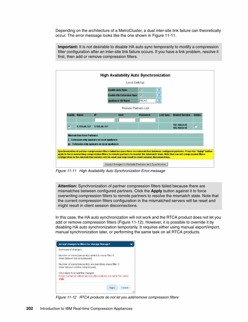
Depending on the architecture of a MetroCluster, a dual inter-site link failure can theoretically occur. The error message looks like the one shown in Figure 11-11.
Figure 11-11 High Availability Auto Synchronization Error message
In this case, the HA auto synchronization will not work and the RTCA product does not let you add or remove compression filters (Figure 11-12). However, it is possible to override it by disabling HA auto synchronization temporarily. It requires either using manual export/import, manual synchronization later, or performing the same task on all RTCA products.
Figure 11-12 RTCA products do not let you add/remove compression filters
Important: It is not desirable to disable HA auto sync temporarily to modify a compression filter configuration after an inter-site link failure occurs. If you have a link problem, resolve it first, then add or remove compression filters.
Attention: Synchronization of partner compression filters failed because there are mismatches between configured partners. Click the Apply button against it to force overwriting compression filters to remote partners to resolve the mismatch state. Note that the current compression filters configuration in the mismatched servers will be reset and might result in client session disconnections.
202 Introduction to IBM Real-time Compression Appliances

11.5 N series with MultiStore
The N series MultiStore feature provides the ability to configure virtual filers within a physical N series system. This feature is fully supported by the RTCA product, with each virtual filer (vfiler) configured as if it was a physical storage system. In other words, a vfiler is just another storage object in an RTCA configuration.
11.5.1 Considerations for vfilers
There are no special considerations for vfilers other than configuring their IP addresses and filters on all the RTCA products that might service them at any given time. This is mostly important if vfilers are replicated between an N series cluster and another one, such as with the DataMotion feature. In this environment there typically are four N series controllers. NAS1a and NAS1b are the primary dual node system, and NAS2a and NAS2b are the secondary dual system, being the replica as illustrated in Figure 11-13.
11.5.2 Types of configurations
In the following sections, we describe the various configurations possible.
RTCA product configurationSTN1 is configured as an HA pair with STN2, STN3, and STN4. All four RTCA products are configured with all the vfiler IP addresses. The configuration of compression filters is performed only on one RTCA product, for example, STN1 to avoid synchronization issues. In such a configuration, it is best to build a star topology for the configuration of HA Auto Sync; in other words, STN1 is master and paired with STN2, STN3, STN4. The HA configuration is similar to the RTCA product design in the MetroCluster example in Figure 11-10 on page 201.
Port connectivityAny network configuration from the foregoing examples, typically a clustered NAS with active/passive failover on EtherChannel/LACP bonds, is usable for MultiStore configurations.
Chapter 11. NAS / N series solution design 203
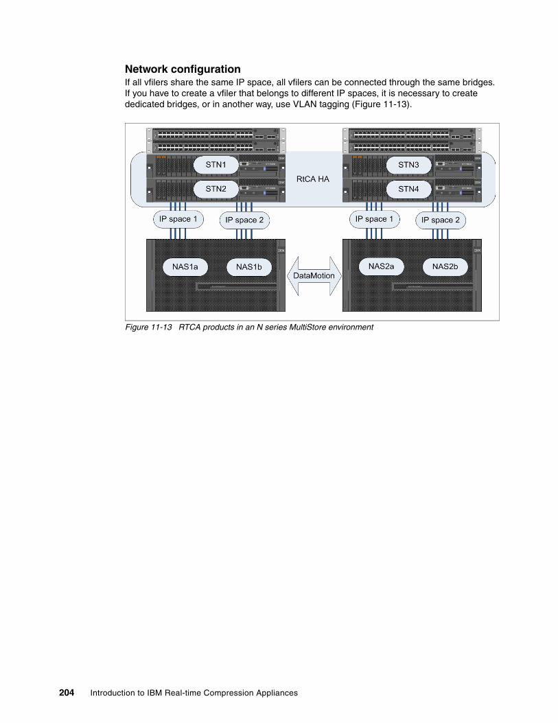
Network configurationIf all vfilers share the same IP space, all vfilers can be connected through the same bridges. If you have to create a vfiler that belongs to different IP spaces, it is necessary to create dedicated bridges, or in another way, use VLAN tagging (Figure 11-13).
Figure 11-13 RTCA products in an N series MultiStore environment
204 Introduction to IBM Real-time Compression Appliances
Chapter 12. EMC storage integration
In this chapter, we discuss IBM Real-time Compression Appliance solutions in a data center environment with EMC supported NAS storage configurations.
The reader will be able to understand the benefits and easy implementation of the IBM RTCA product in any of the supported NAS environments. These include IBM N series, Netapp, and also EMC Celerra.
For example, if the EMC Celerra storage system is already installed in a data center environment, we can also think about a compression engine solution. Suppose that the customer is using EMC Celerra storage and they have performance and capacity improvement issues. The correct approach will be to offer the benefit of the IBM Real-time Compression Appliance solution and explain how it can meet their expectations.
This chapter provides the following details:
� Planning information� IBM RTCA value added benefits� IBM RTCA implementation in EMC NAS environment
First we are going to discuss the basic steps before and during the installation process and validation of the system.
12
© Copyright IBM Corp. 2013. All rights reserved. 205

12.1 Planning information
This section demonstrates the proper installation and implementation procedure for the IBM Real Time Compression Appliance solution with EMC storage. The most important step for finding a proper solution is pre-installing the IBM Technical and Delivery Assessment (TDA) process. The TDA process is part of the IBM Solutions Assurance procedure and it is very important in finding a proper solution. Pre-installation of TDA must be done before installation of the IBM RTCA solution. You need to meet all the IBM requirements for pre-installing TDA. Contact your local IBM or Business Partner contact to request this service offering.
Physical configuration and installation planning for the IBM Real-time Compression Appliance is the customer’s responsibility; the customer must install the machine.
http://www-01.ibm.com/common/ssi/rep_ca/6/877/ENUSZG10-0406/ENUSZG10-0406.PDF
12.2 IBM RTCA value added benefits
Comparing the IBM Real-time Compression Appliance with other builds in firmware NAS storage compression engines, the main performance benefits are as follows:
� All compression processes are segregated from the main NAS storage systems and processed in the external appliance module or modules (if RTCA HA is included).
� The NAS storage CPUs are only dedicated to input/output operations and handle advanced storage features such as point-in-time copy, local or external data replication, data mirroring, RAID features, and so on.
� When using internal NAS compression features, there may be increased CPU utilization visible, as compression related tasks will utilize the NAS appliance CPU directly. In contrast, when using an external appliance, there is CPU performance off-load in place for the NAS appliance.
� There is easy management regulation.
� Fast segregation of problems expedites troubleshooting procedures.
These are the main improvements that we can accomplish using the IBM RTCA solution in any supported NAS environments:
� The RTCA compression dramatically decreases storage capacity, depending on file types or the application environment. The compression ratio can go from 30% up to 80%.
� Supporting online and active primary applications.
� Optimizing and leveraging investments in existing storage and new storage solutions.
� Analyzing compression status and Random Access Compression Engine (RACE) engagement during the data store process. We can easily determine which files are used most and which files are ready for the next step in data store process: archiving.
� Managing more data per defined time.
� Enhancing energy efficiency.
� Reducing capital and operating costs.
Important: Only a person with knowledge and experience must install this product, because only in that case can customers expect a safe RTCA implementation, following good safety practices. We strongly advise using IBM Implementation Services. For more information, contact your local IBM sales representative.
206 Introduction to IBM Real-time Compression Appliances
12.3 IBM RTCA implementation in EMC NAS environments
In the IBM RTCA interoperability matrix, we can see that the only supported NAS vendors are IBM N series, Netapp, and EMC Celerra. We have already described the IBM N series and Netapp in the previous chapters. We can now explain in a simple way whether the IBM RTCA product can be implemented in a customer EMC Celerra environment.
The EMC Celerra is EMC’s NAS product and it too has high availability network features like other NAS storage systems such as IBM N series and Netapp. Here we describe two possible ways of using the IBM RTCA product with the EMC NAS storage system:
� The first solution is applied when EMC Celerra has already been installed and is working in a current data environment and the IBM RTCA product must be installed within it.
� The second solution is applied when a customer wants to use EMC Celerra system along with the compression engine feature. In that case we install IBM RTCA and EMC Celerra from the beginning.
12.3.1 The first option
Here, the EMC Celerra storage has already been installed and it is running. The customer wants to implement a compression engine in the current solution without decreasing the storage performance. In that case, we need to offer an external appliance that resolves the compression engine without the issue of decreasing storage performance. In addition, the other benefits possible are described in “IBM RTCA value added benefits” on page 206.
Suppose the current EMC Celerra storage system has been properly installed in the network with a high availability (HA) solution. In this case, implementing the IBM RTCA product can be easily done without destroying the current production system, as shown in Figure 12-1.
We must check whether the HA network feature on EMC Celerra is properly installed and configured. If it is not, the first step in implementation must be installing network HA on the storage system.
EMC Celerra has “Filesafe networking” interfaces for failover of physical network ports. “Filesafe networking” allows network ports to have a dedicated passive (backup) port on a separate network card in case of failure. It is not important whether the reason for the failure has been a physical network card in the storage system, an external network switch, or a router. “Filesafe networking” will handle the failover on the physical network card on the EMC Celerra. Every physical port on EMC Celerra supports two standards for aggregation. One is the industry standard Link Aggregation IEEE802.3ad and the other is Ethernet Port Trunking.
Chapter 12. EMC storage integration 207

Next we describe the procedure for implementing the IBM RTCA in an EMC Celerra environment.
Step 1. We advise that you first check the NAS Storage (EMC Celerra) failover data path configuration. If it is OK and the configuration is similar, as shown in Figure 12-1, we can go to the next step. If the failover data path is not configured as we discussed, the first step in the IBM RTCA implementation must be to reconfigure EMC Celerra data paths.
Figure 12-1 RTCA and NAS integration without single point of path failure
208 Introduction to IBM Real-time Compression Appliances

Step 2. All data must be transferred through predefined active storage paths (Figure 12-2). Backup data paths will be used for IBM RTCA implementation. When we implement the IBM RTCA product using backup data paths, then we will create and configure IBM RTCA bonds and bridges.
Figure 12-2 All data transferred through the active data path
Chapter 12. EMC storage integration 209
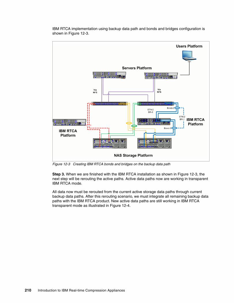
IBM RTCA implementation using backup data path and bonds and bridges configuration is shown in Figure 12-3.
Figure 12-3 Creating IBM RTCA bonds and bridges on the backup data path
Step 3. When we are finished with the IBM RTCA installation as shown in Figure 12-3, the next step will be rerouting the active paths. Active data paths now are working in transparent IBM RTCA mode.
All data now must be rerouted from the current active storage data paths through current backup data paths. After this rerouting scenario, we must integrate all remaining backup data paths with the IBM RTCA product. New active data paths are still working in IBM RTCA transparent mode as illustrated in Figure 12-4.
210 Introduction to IBM Real-time Compression Appliances

Figure 12-4 IBM RTCA bonds and bridges on the active and backup data path
Step 4. After the IBM RTCA integration is completed within the NAS storage environment, we can start working with the compression engine.
The final configuration with the IBM RTCA product implemented in the environment is shown in Figure 12-5.
Figure 12-5 IBM RTCA completed integration in NAS Storage environment
Chapter 12. EMC storage integration 211
12.3.2 The second option
Suppose that a customer wants to use the EMC Celerra storage system but needs a data compression engine without decreasing the storage performance. In this case, we can implement IBM RTCA and EMC Celerra storage from the beginning. We install all storage components, create logical structure of storage, define and implement network solution. On the storage side, properly install network failover and both active and passive physical ports on the storage machine. The IBM RTCA appliance will be included in the solution before the time of production. The whole solution made of EMC Celerra storage system, IBM RTCA appliance, network switches will be implemented, tested and verified and only then can we confirm that the solution is ready for production.
During these IBM RTCA implementation steps, we use planning and deploying information as described in the related sections as a necessary procedure for installation. The final solution with high availability features created in the storage, RTCA, and network level is shown in Figure 12-5 on page 211.
The most important thing during the storage configuration is to prepare the storage system for primary and redundancy data paths through Ethernet switches (primary and redundancy switches for network high availability).
Also very important is the fact that the IBM RTCA product can be installed in a one-node configuration. but this is not desirable. In that case we do not have an HA appliance solution, we have a single point of failure for data paths and for the appliance. Having only one compression appliance is a single point of failure. Because of that, we strongly advise using a two-way RTCA configuration. An HA solution is reached with a minimum of primary and redundancy data path, network, and appliance high availability. This is shown in “IBM RTCA completed integration in NAS Storage environment” on page 211.
In order to ensure that your environment will function properly at all times, make sure that all system and components within your solution are supported.
212 Introduction to IBM Real-time Compression Appliances
Chapter 13. Nearline and offline backup solutions
In this chapter, we explain how to combine the IBM Real-time Compression Appliance with several nearline and offline backup solutions. This will enable the reader to understand the benefits of real-time compression in the complete data life-cycle.
13
© Copyright IBM Corp. 2013. All rights reserved. 213
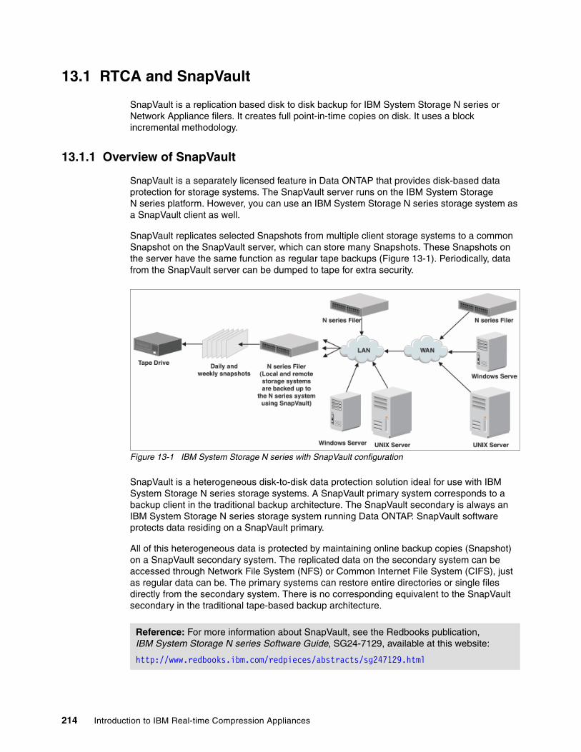
13.1 RTCA and SnapVault
SnapVault is a replication based disk to disk backup for IBM System Storage N series or Network Appliance filers. It creates full point-in-time copies on disk. It uses a block incremental methodology.
13.1.1 Overview of SnapVault
SnapVault is a separately licensed feature in Data ONTAP that provides disk-based data protection for storage systems. The SnapVault server runs on the IBM System Storage N series platform. However, you can use an IBM System Storage N series storage system as a SnapVault client as well.
SnapVault replicates selected Snapshots from multiple client storage systems to a common Snapshot on the SnapVault server, which can store many Snapshots. These Snapshots on the server have the same function as regular tape backups (Figure 13-1). Periodically, data from the SnapVault server can be dumped to tape for extra security.
Figure 13-1 IBM System Storage N series with SnapVault configuration
SnapVault is a heterogeneous disk-to-disk data protection solution ideal for use with IBM System Storage N series storage systems. A SnapVault primary system corresponds to a backup client in the traditional backup architecture. The SnapVault secondary is always an IBM System Storage N series storage system running Data ONTAP. SnapVault software protects data residing on a SnapVault primary.
All of this heterogeneous data is protected by maintaining online backup copies (Snapshot) on a SnapVault secondary system. The replicated data on the secondary system can be accessed through Network File System (NFS) or Common Internet File System (CIFS), just as regular data can be. The primary systems can restore entire directories or single files directly from the secondary system. There is no corresponding equivalent to the SnapVault secondary in the traditional tape-based backup architecture.
Reference: For more information about SnapVault, see the Redbooks publication, IBM System Storage N series Software Guide, SG24-7129, available at this website:
http://www.redbooks.ibm.com/redpieces/abstracts/sg247129.html
214 Introduction to IBM Real-time Compression Appliances
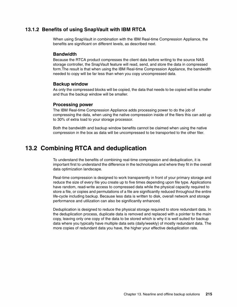
13.1.2 Benefits of using SnapVault with IBM RTCA
When using SnapVault in combination with the IBM Real-time Compression Appliance, the benefits are significant on different levels, as described next.
BandwidthBecause the RTCA product compresses the client data before writing to the source NAS storage controller, the SnapVault feature will read, send, and store the data in compressed form.The result is that when using the IBM Real-time Compression Appliance, the bandwidth needed to copy will be far less than when you copy uncompressed data.
Backup windowAs only the compressed blocks will be copied, the data that needs to be copied will be smaller and thus the backup window will be smaller.
Processing powerThe IBM Real-time Compression Appliance adds processing power to do the job of compressing the data, when using the native compression inside of the filers this can add up to 30% of extra load to your storage processor.
Both the bandwidth and backup window benefits cannot be claimed when using the native compression in the box as data will be uncompressed to be transported to the other filer.
13.2 Combining RTCA and deduplication
To understand the benefits of combining real-time compression and deduplication, it is important first to understand the difference in the technologies and where they fit in the overall data optimization landscape.
Real-time compression is designed to work transparently in front of your primary storage and reduce the size of every file you create up to five times depending upon file type. Applications have random, read-write access to compressed data while the physical capacity required to store a file, or copies and permutations of a file are significantly reduced throughout the entire life-cycle including backup. Because less data is written to disk, overall network and storage performance and utilization can also be significantly enhanced.
Deduplication is designed to reduce the physical storage required to store redundant data. In the deduplication process, duplicate data is removed and replaced with a pointer to the main copy, leaving only one copy of the data to be stored which is why it is well suited for backup data where you typically have multiple data sets (daily/weekly) of mostly redundant data. The more copies of redundant data you have, the higher your effective deduplication rate.
Chapter 13. Nearline and offline backup solutions 215
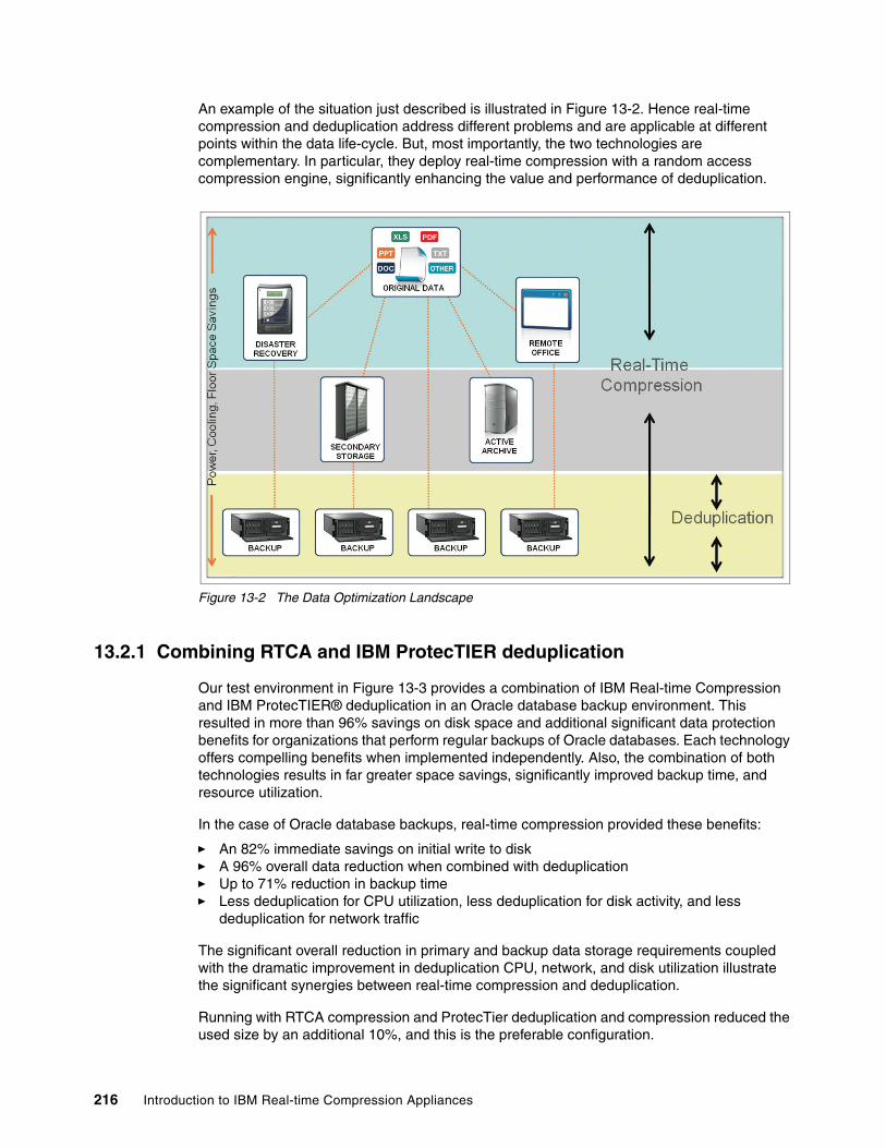
An example of the situation just described is illustrated in Figure 13-2. Hence real-time compression and deduplication address different problems and are applicable at different points within the data life-cycle. But, most importantly, the two technologies are complementary. In particular, they deploy real-time compression with a random access compression engine, significantly enhancing the value and performance of deduplication.
Figure 13-2 The Data Optimization Landscape
13.2.1 Combining RTCA and IBM ProtecTIER deduplication
Our test environment in Figure 13-3 provides a combination of IBM Real-time Compression and IBM ProtecTIER® deduplication in an Oracle database backup environment. This resulted in more than 96% savings on disk space and additional significant data protection benefits for organizations that perform regular backups of Oracle databases. Each technology offers compelling benefits when implemented independently. Also, the combination of both technologies results in far greater space savings, significantly improved backup time, and resource utilization.
In the case of Oracle database backups, real-time compression provided these benefits:
� An 82% immediate savings on initial write to disk� A 96% overall data reduction when combined with deduplication � Up to 71% reduction in backup time� Less deduplication for CPU utilization, less deduplication for disk activity, and less
deduplication for network traffic
The significant overall reduction in primary and backup data storage requirements coupled with the dramatic improvement in deduplication CPU, network, and disk utilization illustrate the significant synergies between real-time compression and deduplication.
Running with RTCA compression and ProtecTier deduplication and compression reduced the used size by an additional 10%, and this is the preferable configuration.
216 Introduction to IBM Real-time Compression Appliances
Figure 13-3 RTCA and ProtecTIER test setup for Oracle environment
Based on the ProtecTIER logs review, the RTCA absorbs all the small changes and prepares the data for the ProtecTIER in a more linear way, allowing it to store the deduplicated data much more efficiently.
Chapter 13. Nearline and offline backup solutions 217
13.2.2 RTCA and EMC Data Domain
As for the previous test in 13.2.1, “Combining RTCA and IBM ProtecTIER deduplication” on page 216, IBM used a similar test setup for the IBM Real-time Compression Appliance in combination with EMC’s Data Domain Appliance.
The combination of IBM Real-time Compression and EMC Data Domain deduplication can result in enhanced overall storage efficiency, as well as significant reductions in deduplication requirements for system CPU and disk utilization and network bandwidth. In the case of Oracle database backups, IBM Real-time Compression provided these benefits:
� More than 80 percent immediate savings on initial write to disk
� More than 93 percent overall reduction in storage space when combined with deduplication
� A 72% reduction in backup time
� A 74% reduction in deduplication CPU utilization
� A 67% reduction in deduplication disk activity
� A 77% reduction in deduplication network traffic
The significant overall reduction in primary and backup data storage requirements, coupled with the dramatic reduction in requirements for deduplication system and network resources, illustrates the significant synergies between real-time compression and deduplication.
The combination of IBM Real-time Compression and the deduplication capabilities of EMC Data Domain products in an Oracle database backup environment resulted in more than 93 percent savings on disk space as well as additional significant data protection benefits. Whereas each technology offers compelling benefits when implemented independently, the combination of the two technologies results in far greater space savings, significantly improved backup time, and better resource utilization.
For more information, see IBM Real-time Compression and EMC Data Domain deduplication: Working together, at the following website:
http://public.dhe.ibm.com/common/ssi/ecm/en/tsw03082usen/TSW03082USEN.PDF
13.3 IBM RTCA and NDMP backup to tape
The NDMP is a standardized protocol for controlling backup, recovery, and other transfers of data between primary and secondary storage devices such as storage systems and tape libraries.
By enabling NDMP protocol support on a storage system, you enable that storage system to carry out communications with various components. These include NDMP-enabled commercial network-attached backup applications (also called data management applications, or DMAs), data servers, and tape servers participating in backup or recovery operations.
NDMP also provides low-level control of tape devices and medium changers.
Data ONTAP NDMP backup and recovery operations use the same dump and restore services that you might use for data backup to tape and data restoration from tape. However, accessing these data protection services through backup applications that support NDMP offers a number of advantages.
218 Introduction to IBM Real-time Compression Appliances
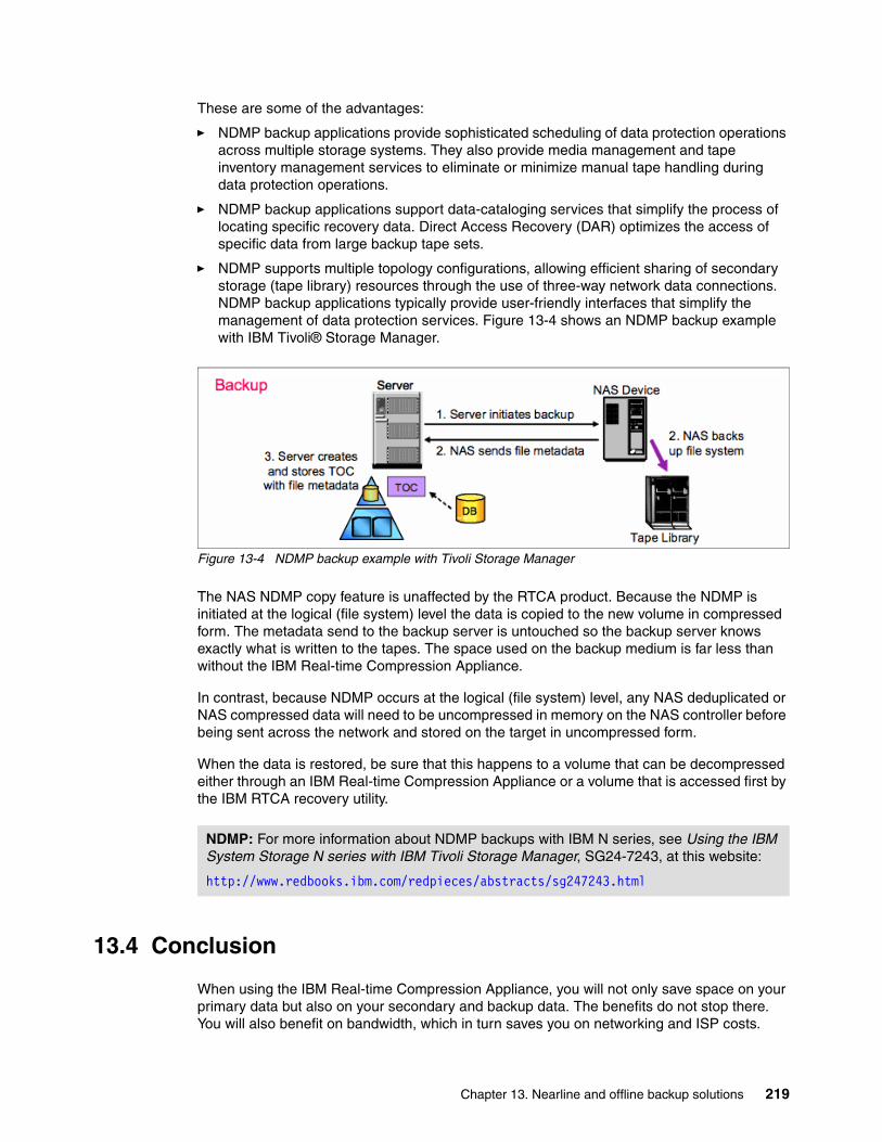
These are some of the advantages:
� NDMP backup applications provide sophisticated scheduling of data protection operations across multiple storage systems. They also provide media management and tape inventory management services to eliminate or minimize manual tape handling during data protection operations.
� NDMP backup applications support data-cataloging services that simplify the process of locating specific recovery data. Direct Access Recovery (DAR) optimizes the access of specific data from large backup tape sets.
� NDMP supports multiple topology configurations, allowing efficient sharing of secondary storage (tape library) resources through the use of three-way network data connections. NDMP backup applications typically provide user-friendly interfaces that simplify the management of data protection services. Figure 13-4 shows an NDMP backup example with IBM Tivoli® Storage Manager.
Figure 13-4 NDMP backup example with Tivoli Storage Manager
The NAS NDMP copy feature is unaffected by the RTCA product. Because the NDMP is initiated at the logical (file system) level the data is copied to the new volume in compressed form. The metadata send to the backup server is untouched so the backup server knows exactly what is written to the tapes. The space used on the backup medium is far less than without the IBM Real-time Compression Appliance.
In contrast, because NDMP occurs at the logical (file system) level, any NAS deduplicated or NAS compressed data will need to be uncompressed in memory on the NAS controller before being sent across the network and stored on the target in uncompressed form.
When the data is restored, be sure that this happens to a volume that can be decompressed either through an IBM Real-time Compression Appliance or a volume that is accessed first by the IBM RTCA recovery utility.
13.4 Conclusion
When using the IBM Real-time Compression Appliance, you will not only save space on your primary data but also on your secondary and backup data. The benefits do not stop there. You will also benefit on bandwidth, which in turn saves you on networking and ISP costs.
NDMP: For more information about NDMP backups with IBM N series, see Using the IBM System Storage N series with IBM Tivoli Storage Manager, SG24-7243, at this website:
http://www.redbooks.ibm.com/redpieces/abstracts/sg247243.html
Chapter 13. Nearline and offline backup solutions 219

220 Introduction to IBM Real-time Compression Appliances
Chapter 14. VMware vSphere integration
In this chapter, we provide the best practices that we advise for use with virtualization.
More specifically, for virtualization with VMware, we discuss best practices regarding the following topics:
� Setup of the IBM N series for use with VMware� VMware vSphere and use with NFS datastores� The network environment for use with VMware and NFS datastores� The use of VMware with the IBM Real-time Compression Appliance
In addition, from 14.6, “Planning for implementation” on page 237 onwards, we have included a user example that provides a practical approach on how to implement the IBM Real-time Compression Appliance when using VMware with NFS datastores.
14
© Copyright IBM Corp. 2013. All rights reserved. 221

14.1 IBM N series and VMware vSphere
This section briefly covers the use of VMware vSphere with an IBM N series system.
14.1.1 vSphere in an N series MetroCluster environment
N series MetroCluster configurations consist of a pair of active-active storage controllers configured with mirrored aggregates and extended distance capabilities to create a high-availability solution. The primary benefits are as follows:
� Higher availability with geographic protection� Minimal risk of lost data, easier management and recovery, and reduced system downtime� Quicker recovery when a disaster occurs� Minimal disruption to users and client applications
A MetroCluster (either Stretch or Fabric) behaves in most ways similar to an active-active configuration. All of the protection provided by core N series technology (RAID-DP, snapshot copies, automatic controller failover) also exists in a MetroCluster configuration. MetroCluster adds, however, complete synchronous mirroring and the ability to perform a complete site failover, from a storage perspective, with a single command.
The following N series MetroCluster types exist and work seamlessly with the complete VMware vSphere and ESX server portfolio:
� Stretch MetroCluster (sometimes referred to as nonswitched):
This type is an active-active configuration that can extend up to 500 m, depending on speed and cable type. It also includes synchronous mirroring (SyncMirror) and the ability to do a site failover with a single command.
� Fabric MetroCluster (also referred to as switched):
This type uses four Fibre Channel switches in a dual-fabric configuration and a separate cluster interconnect card to achieve an even greater distance (up to 100 km depending on speed and cable type) between primary and secondary locations.
14.1.2 Integration and redundancy
The integration of the MetroCluster and VMware vSphere provides seamless integration, and storage and application redundancy. In addition to connecting to the vSphere environment using FCP, iSCSI, or NFS, the solution is able to serve other network clients with CIFS, HTTP, and FTP at the same time. The solution shown Figure 14-1 provides redundant VMware vSphere server, redundant N series heads, and redundant storage.
Reference: This section is an abstract of the Redbooks publication, IBM System Storage N series and VMware vSphere Storage Best Practices, SG24-7871. For current information, see the following website:
http://www.redbooks.ibm.com/abstracts/sg247871.html
222 Introduction to IBM Real-time Compression Appliances

Figure 14-1 MetroCluster and VMware vSphere integrated solution
For more information about N series MetroCluster, see the “MetroCluster” chapter in IBM System Storage N series, SG24-7129.
14.2 VMware vSphere and NFS datastores
This section briefly covers the use of NFS datastores on an IBM N series with a VMware vSphere environment.
14.2.1 Increasing the number of NFS datastores
By default, VMware ESX is configured with eight NFS datastores. However, this limit can be increased to 64 in order to meet the needs as the virtual infrastructure grows. Although the maximum number of NFS datastores (64) is less than what is available with VMFS datastores (256), this difference is offset by the density available to N series NFS datastores.
To be sure of availability, increase the maximum number of datastores available when deploying a VMware ESX Server. This is because pre configuring this setting ensures that NFS datastores can be dynamically added at any time without disruption or effort.
Reference: This section is an abstract of the Redbooks publication, IBM System Storage N series and VMware vSphere Storage Best Practices, SG24-7871. For current information, see the following website:
http://www.redbooks.ibm.com/abstracts/sg247871.html
Chapter 14. VMware vSphere integration 223

To make this change, perform the following steps from within the virtual infrastructure client:
1. Open vCenter Server.
2. Select a VMware ESX host.
3. Select the Configuration tab.
4. In the Software box, select Advanced Configuration.
5. In the dialog box (left pane), select NFS.
6. Change the value of NFS.MaxVolumes to 64 (see Figure 14-2).
7. In the dialog box (left pane), select Net.
8. Change the value of Net.TcpIpHeapSize to 30.
9. Change the value of Net.TcpIpHeapMax to 120.
Repeat the steps for each VMware ESX Server.
Figure 14-2 Increasing the maximum number of NFS datastores
14.2.2 File system security
The N series storage systems permit you to set the security style of each Flexible Volume (or file system) to use UNIX permissions or NTFS permissions. File system security can be mixed and matched with share or export security. As an example, a UNIX share (or export) can allow access to a file system with NTFS permissions and vice versa. In addition, security style can also be made on a file-by-file basis using the MIXED permissions setting.
For VMware ESX deployments, be sure to set the security style of all datastores to UNIX. The security setting of the root volume will be the security setting when a new volume is created.
224 Introduction to IBM Real-time Compression Appliances

Typically, customers who run VMware ESX on NFS want to access their datastores from Windows systems, to be able to complete administrative functions. Considering this situation, set the volume security style to UNIX and make sure that the N series user mapping is set up correctly to enable Windows users access to this data.
If you must change the file system security type, perform the following steps:
1. Log in to the N series console.
2. From the storage appliance console, run the following command:
qtree security <volume path> UNIX
Repeat these steps for each NFS accessed volume.
14.2.3 VMware ESX NFS time-out settings
When connecting to NFS datastores, we advise adjusting a few NFS options around connection monitoring and resiliency. These settings can be automatically set for you if you decide to install the N series VMware ESX Host Utilities. The VMware ESX Host Utilities are supported only with VMware ESX. Therefore, if you are running VMware ESXi, do not install the VMware ESX Host Utilities, but update these settings by performing the following steps:
1. Open vCenter Server.
2. Select a VMware ESX host.
3. Select the Configuration tab.
4. In the Software box, select Advanced Configuration.
5. In the dialog box (left pane) select NFS.
6. Change the value of NFS.HeartbeatFrequency to 12.
7. Change the value of NFS.HeartbeatMaxFailures to 10.
Repeat these steps for each VMware ESX Server.
14.2.4 NFS storage network best practices
As a best practice, be sure to separate IP-based storage traffic from public IP network traffic by implementing separate physical network segments or VLAN segments. This design follows the architecture of SCSI and FC connectivity.
Creating a second network in VMware ESX requires the creation of a second vSwitch to separate the traffic on to other physical NICs. The VMware ESX Server requires a VMkernel port to be defined on the new vSwitch.
Each VMware ESX Server must have a service console port defined on the vSwitch that transmits public virtual machine traffic and on the vSwitch that is configured for IP storage traffic. This second service console port adds the redundancy in VMware ESX HA architectures and follows VMware ESX HA best practices.
With this design, do not allow routing of data between these networks (do not define a default gateway for the NFS storage network). With this model, NFS deployments require a second service console port be defined on the VMkernel storage virtual switch within each VMware ESX server.
Attention: For optimal availability with NFS datastores, make the following changes on each VMware ESX 4.0 host.
Chapter 14. VMware vSphere integration 225

The IP storage network, or VMkernel, connectivity can be verified by the use of the vmkping command. With NFS-connected datastores, the following syntax tests connectivity:
vmkping <NFS IP address>
14.3 VMware vSphere and storage networking
This section briefly covers the use of VMware vSphere with an IBM N series system.
14.3.1 Ethernet storage networking best practices
Use dedicated resources for storage traffic when possible. With Ethernet storage networks, this task can be achieved with separate physical switches, or logically by implementing VLAN segments for storage I/O on a shared, switched IP infrastructure.
One of the challenges of configuring VMware ESX networking for IP storage is that the network configuration must meet all of the following goals:
� Be redundant across switches in a multiswitch environment.� Use as many available physical paths as possible.� Be scalable across multiple physical interfaces.
14.3.2 Virtual LANs (VLANs)
When segmenting network traffic with VLANs, interfaces either can be dedicated to a single VLAN or can support multiple VLANs with VLAN tagging.
For systems that have fewer NICs, such as blade servers, VLANs can be very useful. Channeling two NICs together provides a VMware ESX server with physical link redundancy. By adding multiple VLANs, you can group common IP traffic on separate VLANs for optimal performance, as follows, for example:
� Group the Service console access with the virtual machine network on one VLAN.� The VMkernel activities of IP Storage and vMotion can reside on a second VLAN.
VLANs and VLAN tagging also play a simple but important role in securing an IP storage network. NFS exports can be restricted to a range of IP addresses that are available only on the IP storage VLAN. N series storage systems also allow the restriction of the iSCSI protocol to specific interfaces, VLAN tags, or both.
These simple configuration settings have an enormous effect on the security and availability of IP-based datastores. If you are using multiple VLANs over the same interface, be sure that sufficient throughput can be provided for all traffic.
Tip: You can find general best practices for using NFS in a VMware vSphere environment in the VMware Best Practices Guide for use with NFS datastores. See “Best Practices for running VMware vSphere on Network Attached Storage,” available at this website:
http://www.vmware.com/files/pdf/techpaper/VMware-NFS-BestPractices-WP-EN.pdf
Reference: This section is an abstract of the Redbooks publication, IBM System Storage N series and VMware vSphere Storage Best Practices, SG24-7871. For current information, see the following website:
http://www.redbooks.ibm.com/abstracts/sg247871.html
226 Introduction to IBM Real-time Compression Appliances

14.3.3 Flow control
Flow control is the process of managing the rate of data transmission between two nodes to prevent a fast sender from over running a slow receiver. Flow control can be configured for VMware ESX servers, N series storage systems, and network switches. Be sure to configure the end points: VMware ESX servers and N series storage systems with flow control set to Send ON and Receive OFF.
For network switches, set the switch ports connecting to VMware ESX hosts and N series storage systems to Desired, or if this mode is not available, set these ports to Send OFF and Receive ON (see Figure 14-3).
Figure 14-3 Configuring flow control setting
14.3.4 Spanning tree protocol
The Spanning Tree Protocol (STP) is a network protocol that makes sure of a loop-free topology for any bridged LAN. In the OSI model for computer networking, STP falls under the OSI layer-2. STP allows a network design to include spare (redundant) links to provide automatic backup paths if an active link fails, without the danger of bridge loops, or the need for manual enabling/disabling of these backup links. Bridge loops must be avoided because they result in flooding the network.
When connecting VMware ESX and N series storage systems to Ethernet storage networks, be sure that the Ethernet ports, which these systems connect to, are configured with either Rapid Spanning Tree Protocol (RSTP) or are portfast-disabled.
14.3.5 Bridge Protocol Data Unit (BPDU)
The Bridge Protocol Data Unit (BPDU) exchanges information about bridge IDs and root path costs within STP. When connecting VMware ESX and N series storage systems to Ethernet storage networks, be sure that the Ethernet ports, which these systems connect to, are configured with BPDU disabled.
Tip: The switch ports are configured with the opposite settings of the end points, the VMware ESX and N series systems.
Chapter 14. VMware vSphere integration 227

14.3.6 Virtual Interfaces
A Virtual Network Interface (VIF) is a mechanism that supports aggregation of network interfaces into one logical interface unit. After the VIF is created, it is indistinguishable from a physical network interface. VIFs are used to provide fault tolerance of the network connection and, in certain cases, higher throughput to the storage device.
The N series enables the use of two types of load-balancing VIFs:
� Multimode VIF: This type is a static-configured Ethernet trunk. In a multimode VIF, all of the physical connections in the VIF are simultaneously active and can carry traffic. This mode requires that all of the interfaces be connected to a switch that supports trunking or aggregation over multiple port connections. The switch must be configured to understand that all the port connections share a common MAC address and are part of a single logical interface. In the event of a physical interface failure resulting in the loss of link the VIF will automatically transmit traffic on the surviving links in the VIF without loss of connectivity.
� Dynamic multimode VIF: This type is an LACP-compliant (IEEE 802.3ad) VIF. In a dynamic multimode VIF, all of the physical connections are simultaneously active and carry traffic as with multimode VIFs, described previously. Dynamic multimode VIFs introduce the use of LACP signaling transmissions between the N series storage system and the remote switch. This signaling informs the remote channeling partner of link status. If a failure or inability to transmit data on a link is observed, the device identifying this problem informs the remote channeling partner of the failure, causing the removal of the interface from the VIF. This feature differs from standard multimode VIFs in that there is no signaling between channel partners to inform the remote partner of link failure. The only means for an interface to be removed from a standard multimode VIF is loss of link.
Multimode and dynamic multimode VIFs each use the same algorithm for determining load-balancing. This algorithm is based on source and destination IP or MAC address. Use IP-based source and destination load-balancing especially when the network is designed to route storage traffic. The reason is, because during a transmission of a routed packet, a host transmits the packet to the default router IP address.
When arriving at the router, the router changes the MAC address of the routed packet to the MAC address of the local router interface on which the packet is transmitted out. The changing of the source MAC address can produce situations where traffic arriving from other subnets is always load-balanced to the same physical interfaces in the VIF. IP addresses are not changed unless Network Address Translation (NAT) is used. NAT is rarely used within the data center, where communications between VMware ESX hosts and N series systems occur.
In a single-mode VIF, only one of the physical connections is active at a time. If the storage controller detects a fault in the active connection, a standby connection is activated. No configuration is necessary on the switch to use a single-mode VIF, and the physical interfaces that make up the VIF do not have to connect to the same switch. Note that IP load balancing is not supported on single-mode VIFs.
Another possibility is to create second-level single or multimode VIFs. By using second-level VIFs, you can take advantage of both the link aggregation features of a multimode VIF and the failover capability of a single-mode VIF. In this configuration, two multimode VIFs are created, each one to a separate switch. A single-mode VIF is then created composed of the two multimode VIFs. In normal operation, traffic flows over only one of the multimode VIFs; but if an interface or switch fails, the storage controller moves the network traffic to the other multimode VIF.
228 Introduction to IBM Real-time Compression Appliances
14.3.7 Ethernet switch connectivity
An IP storage infrastructure provides the flexibility to connect to storage in separate ways, depending on the needs of the environment. A basic architecture can provide a single non-redundant link to a datastore, suitable for storing ISO images, various backups, or VM templates. A redundant architecture, suitable for most production environments, has multiple links, providing failover for switches and network interfaces. Link-aggregated and load-balanced environments make use of multiple switches and interfaces simultaneously to provide failover and additional overall throughput for the environment.
More modern Ethernet switch models support cross-stack EtherChannel trunks or virtual port channel trunks, where interfaces on separate physical switches are combined into an IEEE 802.3ad EtherChannel trunk. The advantage of multiswitch EtherChannel trunks is that they can eliminate the need for additional passive links that are accessed only during failure scenarios in certain configurations.
All IP storage networking configuration options covered here use multiple switches and interfaces to provide redundancy and throughput for production VMware environments.
14.4 Best practices for using vSphere and RTCA
This section covers the best practices for using the IBM Real-time Compression Appliance (IBM RTCA product) with VMware vSphere environments. More specifically, we mean the use of the IBM RTCA product with NFS Datastores.
14.4.1 RTCA hardware setup best practices
To ensure high availability in a production environment, a single point of failure is unacceptable. Therefore we advise you to install a redundant high available pair of IBM Real-time Compression Appliances when you decide to implement the IBM RTCA product.
A high available pair of IBM Real-time Compression Appliances is never a true cluster. Both machines simply share information about which shares they compress. Thanks to the transparency and the way the IBM RTCA product compresses the data, this is enough for one IBM RTCA product to take over from another in case of a failure.
However, we do advise you to have a backup of each IBM RTCA configuration file stored in a safe place in case of disaster. This will simplify the restore of a failed IBM RTCA product.
Reference: For more information about how to implement the IBM Real-time Compression Appliance in your network environment, see 14.4.3, “Storage networking best practices” on page 231
Chapter 14. VMware vSphere integration 229
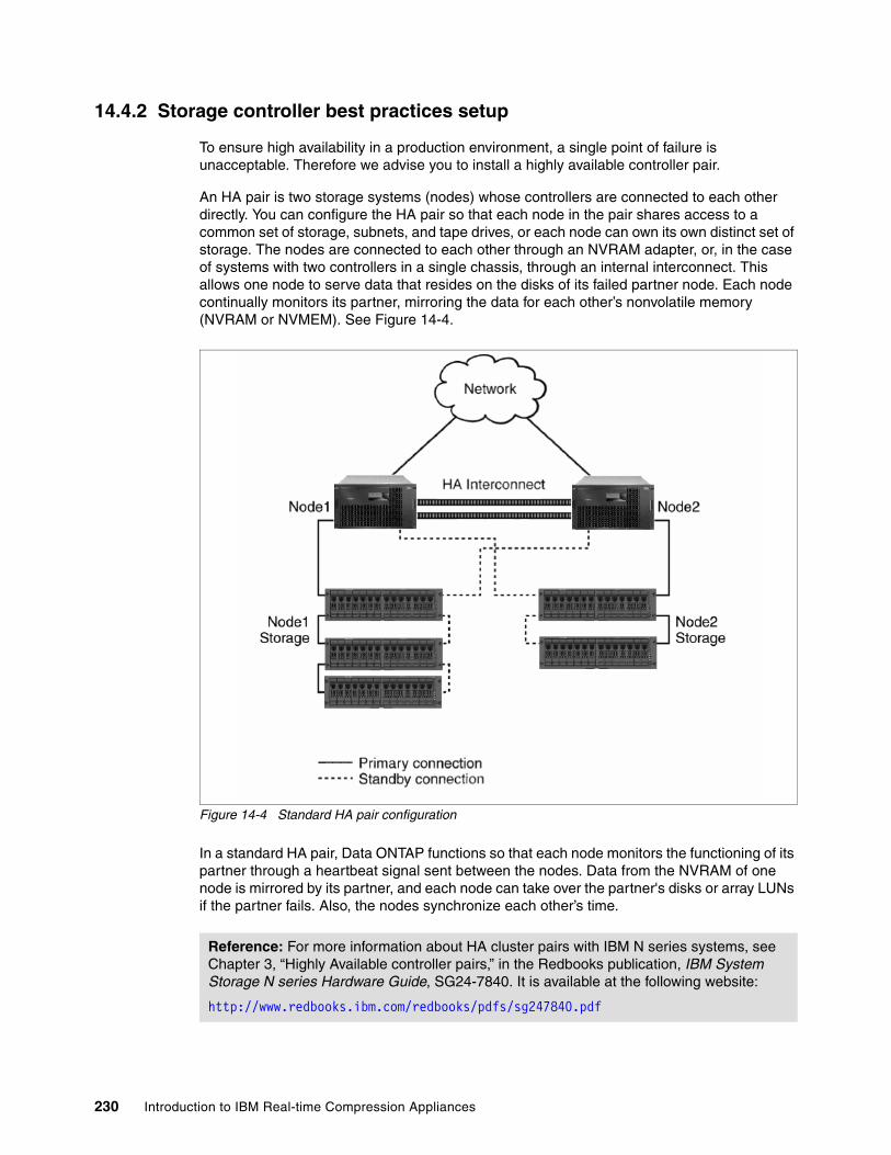
14.4.2 Storage controller best practices setup
To ensure high availability in a production environment, a single point of failure is unacceptable. Therefore we advise you to install a highly available controller pair.
An HA pair is two storage systems (nodes) whose controllers are connected to each other directly. You can configure the HA pair so that each node in the pair shares access to a common set of storage, subnets, and tape drives, or each node can own its own distinct set of storage. The nodes are connected to each other through an NVRAM adapter, or, in the case of systems with two controllers in a single chassis, through an internal interconnect. This allows one node to serve data that resides on the disks of its failed partner node. Each node continually monitors its partner, mirroring the data for each other’s nonvolatile memory (NVRAM or NVMEM). See Figure 14-4.
Figure 14-4 Standard HA pair configuration
In a standard HA pair, Data ONTAP functions so that each node monitors the functioning of its partner through a heartbeat signal sent between the nodes. Data from the NVRAM of one node is mirrored by its partner, and each node can take over the partner's disks or array LUNs if the partner fails. Also, the nodes synchronize each other’s time.
Reference: For more information about HA cluster pairs with IBM N series systems, see Chapter 3, “Highly Available controller pairs,” in the Redbooks publication, IBM System Storage N series Hardware Guide, SG24-7840. It is available at the following website:
http://www.redbooks.ibm.com/redbooks/pdfs/sg247840.pdf
230 Introduction to IBM Real-time Compression Appliances

14.4.3 Storage networking best practices
As a best practice, be sure to separate IP-based storage traffic from public IP network traffic by implementing separate physical network segments or VLAN segments.
Creating a second network in VMware ESX requires the creation of a second vSwitch to separate the traffic on to other physical NICs. The VMware ESX Server requires a VMkernel port to be defined on the new vSwitch.
Each VMware ESX Server must have a service console port defined on the vSwitch that transmits public virtual machine traffic and on the vSwitch that is configured for IP storage traffic. This second service console port adds the redundancy in VMware ESX HA architectures and follows VMware ESX HA best practices.
With this design, do not allow routing of data between these networks (do not define a default gateway for the NFS storage network). With this model, NFS deployments require a second service console port be defined on the VMkernel storage virtual switch within each VMware ESX server.
IP storage network, or VMkernel, connectivity can be verified by the use of the vmkping command. With NFS-connected datastores, the following syntax tests connectivity:
vmkping <NFS IP address>
As the IBM Real-time Compression Appliance does not support multiswitch EtherChannel trunking, and to ensure high availability, the network can be configured in the two ways (represented in Figure 14-6 and Figure 14-7). Each design requires the storage controller to have four physical network connections. Both designs are very similar. They both provide multiple active links to each storage controller, provide a means to scale throughput by simply adding more links, and require multiple IP addresses per controller. Each design uses two physical links for each active network connection in order to achieve path high availability.
The multi layer VIF designThe multi-mode design (see Figure 14-5) requires each storage controller to have at least four physical network connections. The connections are divided into two multimode (active-active) VIFs with IP load balancing enabled, one VIF connected to each of the two switches. These two VIFs are then combined into one single mode (active-passive) VIF. We refer to this configuration as a second-level VIF. This option also requires multiple IP addresses on the storage appliance. Multiple IP addresses can be assigned to the single-mode VIF by using IP address aliases or by using VLAN tagging.
Chapter 14. VMware vSphere integration 231
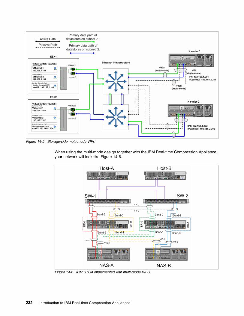
Figure 14-5 Storage-side multi-mode VIFs
When using the multi-mode design together with the IBM Real-time Compression Appliance, your network will look like Figure 14-6.
Figure 14-6 IBM RTCA implemented with multi-mode VIFS
232 Introduction to IBM Real-time Compression Appliances

The single layer VIF designThe single-mode design (Figure 14-7) requires each pair of network links to be configured as a single mode (active passive) VIF. Each VIF has a connection to both switches and has a single IP address assigned to it, providing two IP addresses on each controller. The vif favor command is used to force each VIF to use the appropriate switch for its active interface. This option is preferable because of its simplicity and the lack of any special configuration in the network switches.
Figure 14-7 Single mode VIFs
14.4.4 Virtual machine guest file placement
Virtual machines (VMs) consist of multiple files on datastores. To ensure the best compression and deduplication ratios, we have some file placement advice.
Virtual machine files include these:
� .vmx file� .vmdk file� .vswp file� .log file
Our advice is to keep all files together except for the .vswp file. This file is the swap file for the virtual machine. This machine must be placed on a separate datastore on which you do not use snapshots and deduplication. The reason is that this file will never be the same for any of the virtual machines and will change all the time if used. However, the datastore on which the .vswp file resides can be compressed to save space.
Reference: For more information about VMware best practices on IBM N series storage, see the Redbooks publication, IBM System Storage N series and VMware vSphere Storage Best Practices, SG24-7871. It is available at the following website:
http://www.redbooks.ibm.com/abstracts/sg247871.html
Chapter 14. VMware vSphere integration 233

To change the .vswp file location, follow these steps:
1. Connect to the ESX(i) server or to the vCenter server using the VMware vSphere Client.
2. Select the server and go to the Configuration tab.
3. Select Virtual Machine Swapfile Location and click Edit.
4. Specify the datastore that you want to use for the .vswp files.
5. The new location will be used when the virtual machine restarts.
14.4.5 Block alignment with NFS
When not using the IBM Real-time Compression Appliance, block alignment is a serious consideration. Following is a short description of block alignment, which involves alignment of VM partitions and VMFS to storage arrays.
Virtual machines store their data on virtual disks. As with physical disks, these virtual disks contain storage partitions and file systems, which are created by the VM’s guest operating system. To make sure of optimal disk I/O within the VM, align the partitions of the virtual disks to the block boundaries of VMFS and the block boundaries of the storage array. Failure to align all three items can result in a dramatic increase of I/O load on a storage array and negatively affects the performance of all virtual machines being served on the array.
Be sure that the partitions of VMs and the partitions of VMFS datastores are to be aligned to the blocks of the underlying storage array. For more information about VMFS and GOS file system alignment, see the following documents:
� IBM: Storage Block Alignment with VMware Virtual Infrastructure, NS3593 � VMware: Recommendations for Aligning VMFS Partitions
The IBM Real-time Compression Appliance will try to compress all blocks, and the compression rate of all blocks will be different for every block. This implies that block alignment is a setting that does not need to be considered anymore when using the IBM RTCA.
14.4.6 Considerations regarding deduplication and snapshots
When using deduplication and snapshots, there are considerations to take into account before implementing the IBM Real-time Compression Appliance.
Considerations for deduplicationWhen implementing compression on an NFS datastore that is using deduplication, we have certain considerations. When we run the Compression Accelerator daemon, all data will be rewritten on to the volume. This implies that all existing data will disappear and new compressed data will be written. Because all data disappears, the deduplication ratio will disappear as well. In Example 14-1 we show the df -Sk command before and after the compression accelerator has run.
234 Introduction to IBM Real-time Compression Appliances

Example 14-1 Command df -Sk before and after compression accelerator
Before CAN5600-A> df -SkFilesystem used compressed a-sis %saved/vol/vmware1/ 19047572KB 0KB 21415064KB 53%
After CAN5600-A> df -SkFilesystem used compressed a-sis %saved/vol/vmware1/ 11300908KB 0KB 12KB 0%
As you can see, the percentage saved is reduced to 0% but the used space has lowered by about 40%.
As the data is all new, you need to rerun the command sis start -s <path to the volume>. This command will force the deduplication process to rescan all the data on the volume. After you have started the command, you can monitor the progress of the deduplication process by running the command sis status (Example 14-2).
Example 14-2 Restarting the deduplication process and monitoring it
N5600-A> sis start -s /vol/vmware1The file system will be scanned to process existing data in /vol/vmware1.This operation may initialize related existing metafiles.Are you sure you want to proceed (y/n)? yThe SIS operation for "/vol/vmware1" is started.[N5600-A: wafl.scan.start:info]: Starting SIS volume scan on volume vmware1.
N5600-A> sis statusPath State Status Progress/vol/vmware1 Enabled Active 11 GB Scanned
N5600-A> sis statusPath State Status Progress/vol/vmware1 Enabled Active 10 GB Searched
N5600-A> sis statusPath State Status Progress/vol/vmware1 Enabled Active 235 MB (6%) Done
N5600-A> sis statusPath State Status Progress/vol/vmware1 Enabled Idle Idle for 00:01:21
Attention: Make sure you have enough free space in your volume when turning on compression and when running the Compression Accelerator daemon on volumes that have deduplication turned on.
Chapter 14. VMware vSphere integration 235

Considerations for snapshotsWhen using the IBM Real-time Compression Appliance on volumes with snapshots, one consideration is that all data written through the IBM Real-time Compression Appliance and all data compressed by the Compression Accelerator daemon will be seen as new data.
When new data is written on volumes with snapshots, the old data will reside in the snapshot space, which can fill up quite quickly. This needs to be considered when turning on compression on volumes with snapshots. Make sure you have enough free space in your volume when turning on compression and when running the Compression Accelerator daemon on volumes that have snapshots.
14.5 VMware vSphere user case examples
This section onwards provides a practical approach on how to implement the IBM Real-time Compression Appliance when using VMware with NFS datastores. We start by describing the setup of our test environment and then continue with the implementation steps.Test environment setup
To show you how to implement the IBM Real-time Compression Appliance we used a simple VMware implementation. As shown in Figure 14-8, we use one host connected to a NFS volume that it uses as a datastore. We created six virtual machines, all running Windows 2008 Server. The NFS datastores are presented to the host using an IBM N series cluster. The IBM N series uses multi layered VIFs to be highly available at all time.
Figure 14-8 VMware setup without the IBM Real-time Compression Appliance
236 Introduction to IBM Real-time Compression Appliances
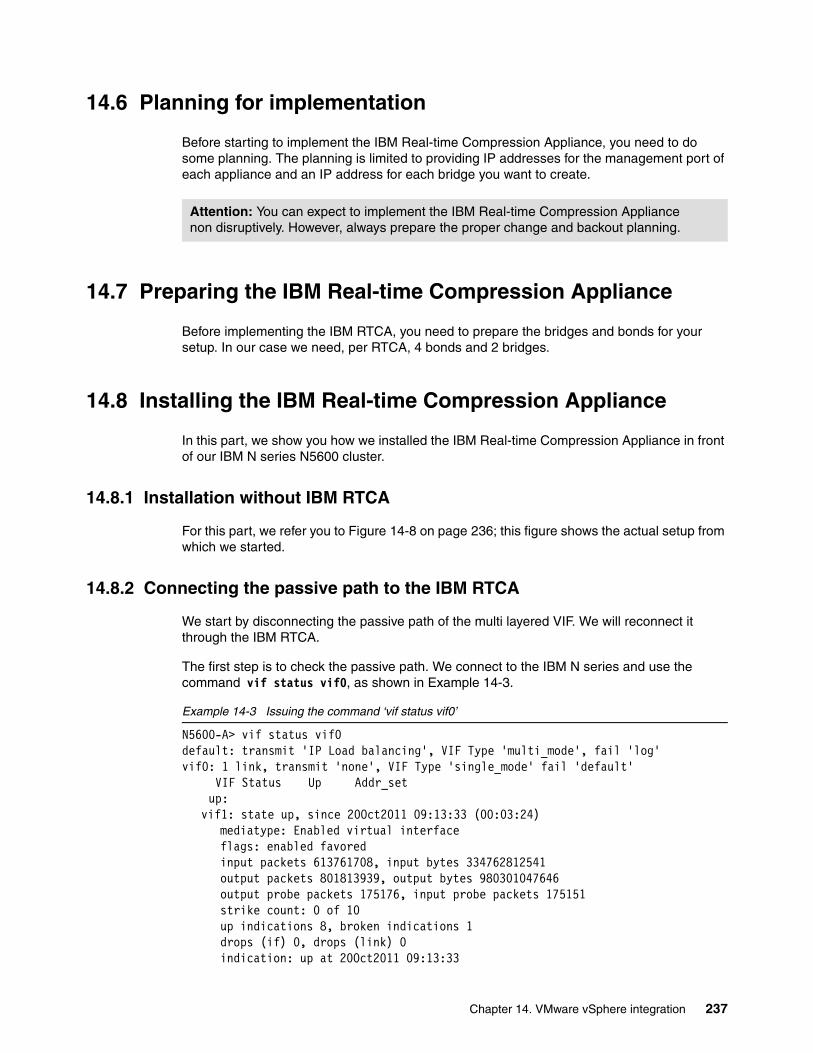
14.6 Planning for implementation
Before starting to implement the IBM Real-time Compression Appliance, you need to do some planning. The planning is limited to providing IP addresses for the management port of each appliance and an IP address for each bridge you want to create.
14.7 Preparing the IBM Real-time Compression Appliance
Before implementing the IBM RTCA, you need to prepare the bridges and bonds for your setup. In our case we need, per RTCA, 4 bonds and 2 bridges.
14.8 Installing the IBM Real-time Compression Appliance
In this part, we show you how we installed the IBM Real-time Compression Appliance in front of our IBM N series N5600 cluster.
14.8.1 Installation without IBM RTCA
For this part, we refer you to Figure 14-8 on page 236; this figure shows the actual setup from which we started.
14.8.2 Connecting the passive path to the IBM RTCA
We start by disconnecting the passive path of the multi layered VIF. We will reconnect it through the IBM RTCA.
The first step is to check the passive path. We connect to the IBM N series and use the command vif status vif0, as shown in Example 14-3.
Example 14-3 Issuing the command ‘vif status vif0’
N5600-A> vif status vif0default: transmit 'IP Load balancing', VIF Type 'multi_mode', fail 'log'vif0: 1 link, transmit 'none', VIF Type 'single_mode' fail 'default' VIF Status Up Addr_set up:
vif1: state up, since 20Oct2011 09:13:33 (00:03:24)mediatype: Enabled virtual interfaceflags: enabled favoredinput packets 613761708, input bytes 334762812541output packets 801813939, output bytes 980301047646output probe packets 175176, input probe packets 175151strike count: 0 of 10up indications 8, broken indications 1drops (if) 0, drops (link) 0indication: up at 20Oct2011 09:13:33
Attention: You can expect to implement the IBM Real-time Compression Appliance non disruptively. However, always prepare the proper change and backout planning.
Chapter 14. VMware vSphere integration 237

consecutive 526118, transitions 9 down:
vif2: state down, since 20Oct2011 09:14:05 (00:02:52)mediatype: Enabled virtual interfaceflags: enabledinput packets 790190606, input bytes 658415884281output packets 831068905, output bytes 819332121433output probe packets 175171, input probe packets 175154strike count: 0 of 10up indications 12, broken indications 4drops (if) 0, drops (link) 0indication: up at 19Oct2011 13:35:11
consecutive 525933, transitions 16
The foregoing example, Example 14-3, shows us that vif1 is active and vif2 is passive. To check which physical ports are connected to vif2, we issue the command vif status vif2 as shown in Example 14-4.
Example 14-4 Issuing the command ‘vif status vif2’
N5600-A> vif status vif2default: transmit 'IP Load balancing', VIF Type 'multi_mode', fail 'log'vif2: 2 links, transmit 'IP Load balancing', VIF Type 'lacp' fail 'default' VIF Status Up Addr_set trunked: vif0 down:
e0d: state up, since 19Oct2011 13:35:11 (19:45:59)mediatype: auto-1000t-fd-upflags: enabledactive aggr, aggr port: e0dinput packets 310599273, input bytes 250955714839input lacp packets 17585, output lacp packets 17610output packets 533670511, output bytes 569553754316up indications 32, broken indications 10drops (if) 0, drops (link) 0indication: up at 19Oct2011 13:35:11
consecutive 0, transitions 42e0b: state up, since 19Oct2011 13:35:11 (19:45:59)
mediatype: auto-1000t-fd-upflags: enabledactive aggr, aggr port: e0dinput packets 479591995, input bytes 407460215291input lacp packets 17582, output lacp packets 17606output packets 297398498, output bytes 249778372961up indications 32, broken indications 10drops (if) 0, drops (link) 0indication: up at 19Oct2011 13:35:11
consecutive 0, transitions 42
Example 14-4 shows us that vif2 consists of port e0b and port e0d. We will disconnect those two ports and connect them to a bond on RTCA2 and reconnect the bond, that is connect to the first bond with a bridge, back to the switch ports. We will do this also for the other IBM N series and connect it to RTCA1. This step is shown in Figure 14-9 on page 239.
238 Introduction to IBM Real-time Compression Appliances
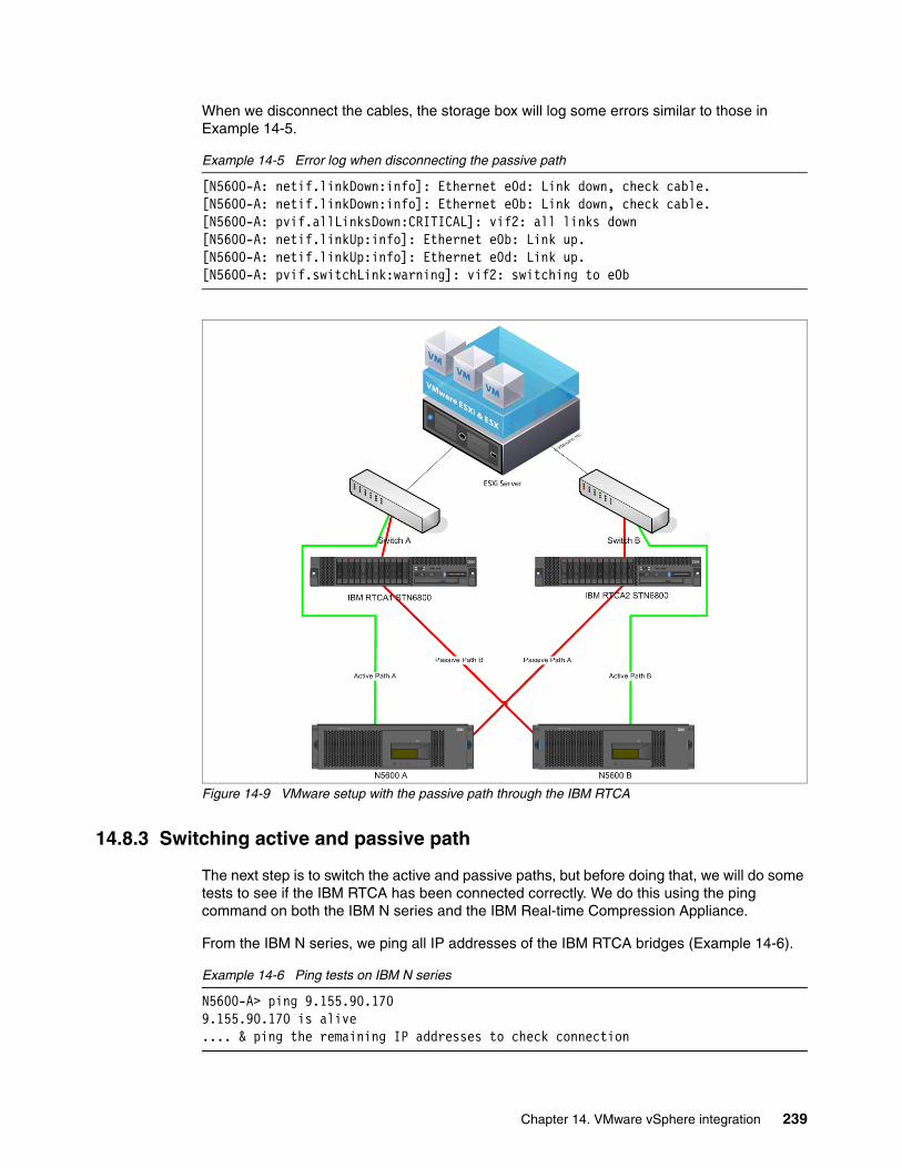
When we disconnect the cables, the storage box will log some errors similar to those in Example 14-5.
Example 14-5 Error log when disconnecting the passive path
[N5600-A: netif.linkDown:info]: Ethernet e0d: Link down, check cable.[N5600-A: netif.linkDown:info]: Ethernet e0b: Link down, check cable.[N5600-A: pvif.allLinksDown:CRITICAL]: vif2: all links down[N5600-A: netif.linkUp:info]: Ethernet e0b: Link up.[N5600-A: netif.linkUp:info]: Ethernet e0d: Link up.[N5600-A: pvif.switchLink:warning]: vif2: switching to e0b
Figure 14-9 VMware setup with the passive path through the IBM RTCA
14.8.3 Switching active and passive path
The next step is to switch the active and passive paths, but before doing that, we will do some tests to see if the IBM RTCA has been connected correctly. We do this using the ping command on both the IBM N series and the IBM Real-time Compression Appliance.
From the IBM N series, we ping all IP addresses of the IBM RTCA bridges (Example 14-6).
Example 14-6 Ping tests on IBM N series
N5600-A> ping 9.155.90.1709.155.90.170 is alive.... & ping the remaining IP addresses to check connection
Chapter 14. VMware vSphere integration 239
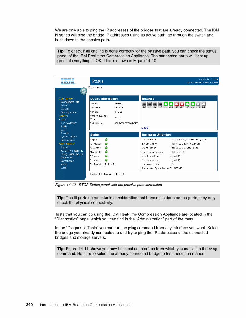
We are only able to ping the IP addresses of the bridges that are already connected. The IBM N series will ping the bridge IP addresses using its active path, go through the switch and back down to the passive path.
Figure 14-10 RTCA Status panel with the passive path connected
Tests that you can do using the IBM Real-time Compression Appliance are located in the “Diagnostics” page, which you can find in the “Administration” part of the menu.
In the “Diagnostic Tools” you can run the ping command from any interface you want. Select the bridge you already connected to and try to ping the IP addresses of the connected bridges and storage servers.
Tip: To check if all cabling is done correctly for the passive path, you can check the status panel of the IBM Real-time Compression Appliance. The connected ports will light up green if everything is OK. This is shown in Figure 14-10.
Tip: The lit ports do not take in consideration that bonding is done on the ports, they only check the physical connectivity.
Tip: Figure 14-11 shows you how to select an interface from which you can issue the ping command. Be sure to select the already connected bridge to test these commands.
240 Introduction to IBM Real-time Compression Appliances

Figure 14-11 Select the interface for the ‘ping’ command
To send the command, simply type in the IP address after selecting the interface and click the ping button. The result will be shown in the web interface (see Figure 14-12).
Figure 14-12 Ping result
When all tests seem alright, you can switch the active and the passive path by issuing the command vif favor <name of vif> (see Example 14-7).
Example 14-7 Issuing the command ‘vif favor <name of vif>’
N5600-A> vif favor vif2[N5600-A: pvif.allLinksDown:CRITICAL]: vif2: all links down[N5600-A: pvif.switchLink:warning]: vif2: switching to e0b[N5600-A: pvif.switchLink:warning]: vif0: switching to vif2[N5600-A: netinet.ethr.duplct.ipAdrr:error]: Duplicate IP address 9.155.90.14!! sent from Ethernet address:00:24:3f:00:22:f6.
Chapter 14. VMware vSphere integration 241
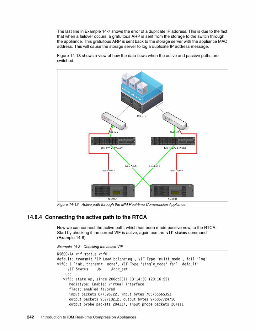
The last line in Example 14-7 shows the error of a duplicate IP address. This is due to the fact that when a failover occurs, a gratuitous ARP is sent from the storage to the switch through the appliance. This gratuitous ARP is sent back to the storage server with the appliance MAC address. This will cause the storage server to log a duplicate IP address message.
Figure 14-13 shows a view of how the data flows when the active and passive paths are switched.
Figure 14-13 Active path through the IBM Real-time Compression Appliance
14.8.4 Connecting the active path to the RTCA
Now we can connect the active path, which has been made passive now, to the RTCA. Start by checking if the correct VIF is active; again use the vif status command (Example 14-8).
Example 14-8 Checking the active VIF
N5600-A> vif status vif0default: transmit 'IP Load balancing', VIF Type 'multi_mode', fail 'log'vif0: 1 link, transmit 'none', VIF Type 'single_mode' fail 'default' VIF Status Up Addr_set up:
vif2: state up, since 20Oct2011 13:14:50 (20:16:55)mediatype: Enabled virtual interfaceflags: enabled favoredinput packets 877095722, input bytes 705765665353output packets 952718212, output bytes 976857724758output probe packets 204137, input probe packets 204111
242 Introduction to IBM Real-time Compression Appliances

strike count: 0 of 10up indications 13, broken indications 4drops (if) 0, drops (link) 0indication: up at 20Oct2011 13:14:50
consecutive 613218, transitions 17 down:
vif1: state down, since 20Oct2011 13:46:43 (19:45:02)mediatype: Enabled virtual interfaceflags: enabledinput packets 693423969, input bytes 393548956950output packets 894087114, output bytes 1082351380001output probe packets 204142, input probe packets 204107strike count: 0 of 10up indications 12, broken indications 5drops (if) 0, drops (link) 0indication: up at 20Oct2011 13:46:43
consecutive 613051, transitions 17
To check which physical port is associated with the VIF, issue the command vif status <name of vif> as shown in Example 14-9.
Example 14-9 Issuing the command ‘vif status vif1’
N5600-A> vif status vif1default: transmit 'IP Load balancing', VIF Type 'multi_mode', fail 'log'vif1: 2 links, transmit 'IP Load balancing', VIF Type 'lacp' fail 'default' VIF Status Up Addr_set trunked: vif0 down:
e0c: state up, since 20Oct2011 13:46:43 (19:50:09)mediatype: auto-1000t-fd-upflags: enabledactive aggr, aggr port: e0ainput packets 422670408, input bytes 215767150480input lacp packets 20486, output lacp packets 20790output packets 850730315, output bytes 1038814078296up indications 33, broken indications 14drops (if) 0, drops (link) 0indication: up at 20Oct2011 13:46:43
consecutive 0, transitions 47e0a: state up, since 20Oct2011 13:46:43 (19:50:09)
mediatype: auto-1000t-fd-upflags: enabledactive aggr, aggr port: e0ainput packets 270754287, input bytes 177781856544input lacp packets 20483, output lacp packets 20791output packets 43356921, output bytes 43537308469up indications 36, broken indications 16drops (if) 0, drops (link) 0indication: up at 20Oct2011 13:46:43
consecutive 0, transitions 52
Example 14-9 shows us that vif1 consists of port e0a and e0c. We will disconnect those two ports and connect them to a bond on RTCA1 and reconnect the bond. That is, we will connect to the first bond with a bridge, back to the switch ports.
Chapter 14. VMware vSphere integration 243
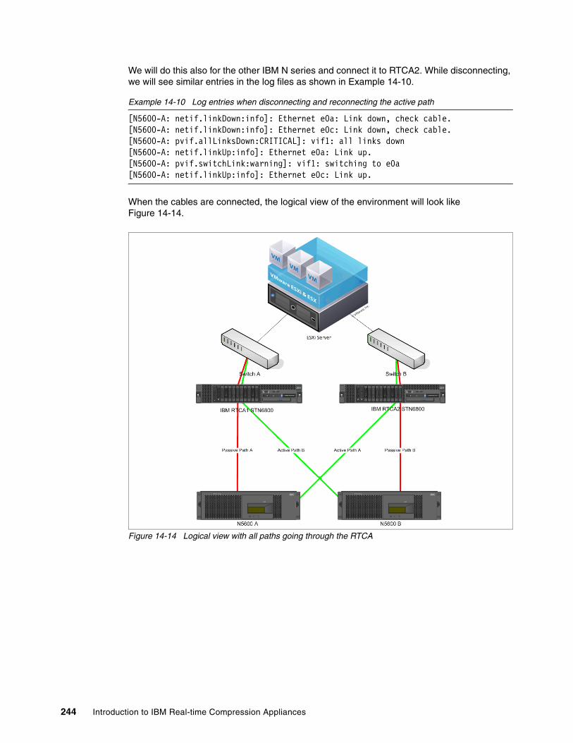
We will do this also for the other IBM N series and connect it to RTCA2. While disconnecting, we will see similar entries in the log files as shown in Example 14-10.
Example 14-10 Log entries when disconnecting and reconnecting the active path
[N5600-A: netif.linkDown:info]: Ethernet e0a: Link down, check cable.[N5600-A: netif.linkDown:info]: Ethernet e0c: Link down, check cable.[N5600-A: pvif.allLinksDown:CRITICAL]: vif1: all links down[N5600-A: netif.linkUp:info]: Ethernet e0a: Link up.[N5600-A: pvif.switchLink:warning]: vif1: switching to e0a[N5600-A: netif.linkUp:info]: Ethernet e0c: Link up.
When the cables are connected, the logical view of the environment will look like Figure 14-14.
Figure 14-14 Logical view with all paths going through the RTCA
244 Introduction to IBM Real-time Compression Appliances

In the web interface of the IBM Real-time Compression Appliance on the Status panel, you will see something such as all connected ports in green, as shown in Figure 14-15.
Figure 14-15 RTCA status panel after all ports are connected
14.8.5 Resetting active paths in the initial state
The last step is to reset the multi layered VIF in its initial active-passive state. We do this by issuing the command vif favor <name of vif>. Example 14-11 provides details of the command.
Example 14-11 Issuing the command ‘vif favor vif1’
N5600-A> vif favor vif1[N5600-A: pvif.allLinksDown:CRITICAL]: vif1: all links down[N5600-A: pvif.switchLink:warning]: vif1: switching to e0a[N5600-A: pvif.switchLink:warning]: vif0: switching to vif1
Chapter 14. VMware vSphere integration 245

The IBM Real-time Compression Appliance is now physically installed. The logical view of the current environment is shown in Figure 14-16.
Figure 14-16 Logical view of the environment
246 Introduction to IBM Real-time Compression Appliances

14.9 Turning on compression
Now that the IBM Real-time Compression Appliance is placed in between the storage and the switches, we can start the compression for certain on all shares or exports.
In Figure 14-17 you can see the status of the IBM Real-time Compression Appliance. All configured Ethernet ports have a green color. The Real-time Compression Engine is running. The bonds are OK. There are no duplicate IPs on the network and the hardware is healthy. We can start off.
Figure 14-17 IBM RTCA Status panel
In the previous caption we installed the IBM RTCA in transparent mode into the data flow. Transparent mode implies that all data will pass through the RTCA without being compressed unless the RTCA is told otherwise.
Chapter 14. VMware vSphere integration 247

We will now tell the Real-time Compression Appliance to compress the data for the VMware volume we are using. We do that by clicking the Storage link under the Configuration menu (see Figure 14-18).
Figure 14-18 Storage page of the RTCA
We check the box next to the share we want to compress. This makes a second check box appear. The new check box is the “no new compression” check box. When we check the no new compression box, the RTCA will not compress newly written data. We only check the compression and then click the Apply button on the top of the page (see Figure 14-19).
Figure 14-19 Select shares to compress
These actions complete the compression setup. All data that will be written to the share from now on will be compressed. The files with extensions that are listed to be excluded will not be compressed. To compress the data that is already written on the share, we have to run the Compression Accelerator. Details on the Compression Accelerator are given in the next part, 14.10, “Setting up the Compression Accelerator” on page 249.
248 Introduction to IBM Real-time Compression Appliances
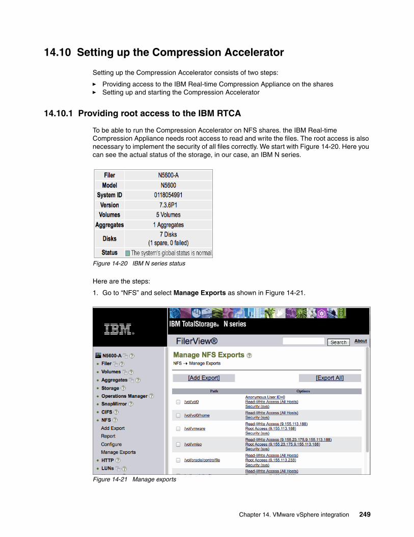
14.10 Setting up the Compression Accelerator
Setting up the Compression Accelerator consists of two steps:
� Providing access to the IBM Real-time Compression Appliance on the shares� Setting up and starting the Compression Accelerator
14.10.1 Providing root access to the IBM RTCA
To be able to run the Compression Accelerator on NFS shares. the IBM Real-time Compression Appliance needs root access to read and write the files. The root access is also necessary to implement the security of all files correctly. We start with Figure 14-20. Here you can see the actual status of the storage, in our case, an IBM N series.
Figure 14-20 IBM N series status
Here are the steps:
1. Go to “NFS” and select Manage Exports as shown in Figure 14-21.
Figure 14-21 Manage exports
Chapter 14. VMware vSphere integration 249

2. Select the export you want to handle by clicking the '/vol/<vol name>' hot link (Figure 14-21).
Figure 14-22 Manage /vol/vmware Export
3. Follow the menu steps until you reach the “Read-Write Hosts” page (Figure 14-23).
Figure 14-23 Read-Write Hosts page
4. Add the IP address of the first bridge by clicking the Add button in Figure 14-23. This will open a pop-up page (Figure 14-24).
Figure 14-24 Add host to read-write access pop-up
5. Click the OK button and repeat this sequence for all bridges.
250 Introduction to IBM Real-time Compression Appliances

All bridges need read and write access to be able to run the Compression Accelerator without any issues (Figure 14-25).
Figure 14-25 All bridges have read and write access
6. By clicking the Next button, you will reach the root access part (Figure 14-26). Click Add to add the IP address of the first bridge.
Figure 14-26 Root Access page
7. Fill in the IP address for the first bridge and click the OK button.
Figure 14-27 Add host for root access
Chapter 14. VMware vSphere integration 251

8. Repeat this sequence for all bridges. All bridges also need root access to be able to set the correct access rights (Figure 14-28).
Figure 14-28 All bridges have Root access
The next page displays the security settings for the export. Just leave these as they are (Figure 14-29).
Figure 14-29 Export Security
9. Click the Next button. You will receive a summary of the changes you want make to this export,
252 Introduction to IBM Real-time Compression Appliances

10.Click the Commit button to commit your changes (Figure 14-30).
Figure 14-30 Summary of changes
11.Close the pop-up window by clicking the Close button (Figure 14-31).
Figure 14-31 Changes are committed successfully
Chapter 14. VMware vSphere integration 253
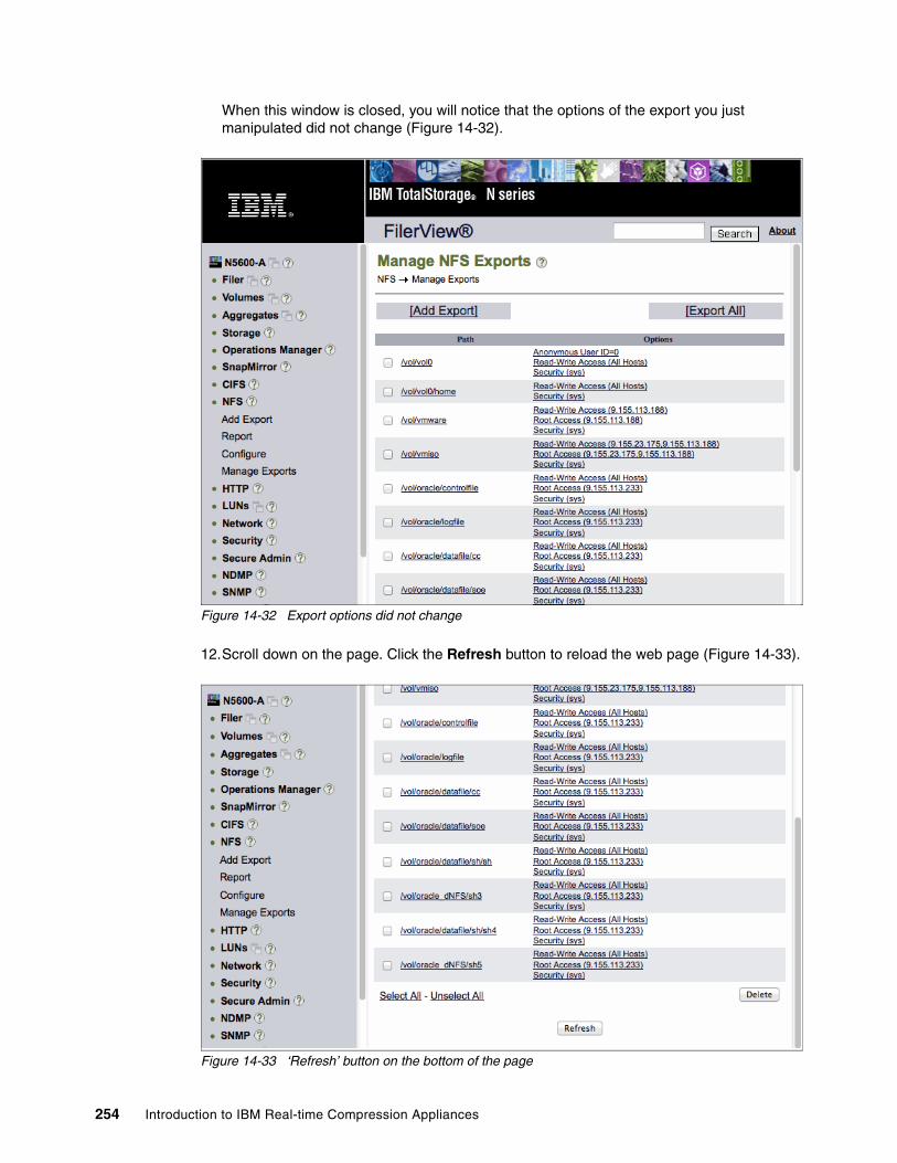
When this window is closed, you will notice that the options of the export you just manipulated did not change (Figure 14-32).
Figure 14-32 Export options did not change
12.Scroll down on the page. Click the Refresh button to reload the web page (Figure 14-33).
Figure 14-33 ‘Refresh’ button on the bottom of the page
254 Introduction to IBM Real-time Compression Appliances
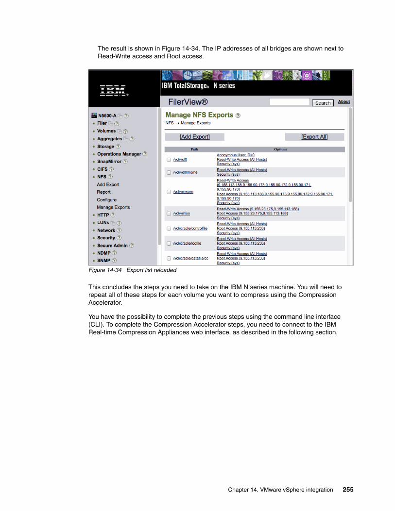
The result is shown in Figure 14-34. The IP addresses of all bridges are shown next to Read-Write access and Root access.
Figure 14-34 Export list reloaded
This concludes the steps you need to take on the IBM N series machine. You will need to repeat all of these steps for each volume you want to compress using the Compression Accelerator.
You have the possibility to complete the previous steps using the command line interface (CLI). To complete the Compression Accelerator steps, you need to connect to the IBM Real-time Compression Appliances web interface, as described in the following section.
Chapter 14. VMware vSphere integration 255
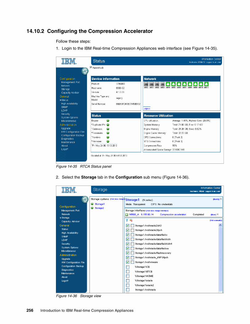
14.10.2 Configuring the Compression Accelerator
Follow these steps:
1. Login to the IBM Real-time Compression Appliances web interface (see Figure 14-35).
Figure 14-35 RTCA Status panel
2. Select the Storage tab in the Configuration sub menu (Figure 14-36).
Figure 14-36 Storage view
256 Introduction to IBM Real-time Compression Appliances

3. To configure the Compression Accelerator, click the Compression Accelerator hot link, which is mentioned on the top of the page. Make sure that the correct storage is selected. If not, select the correct Storage from the side menu (see Figure 14-36 on page 256).
After you have clicked the Compression Accelerator hot link, you will see the “Compression Accelerator Configuration” page (Figure 14-37). Here, you can set the credentials to compress CIFS shares. On top of that, you can set the “Maximum Total Throughput” and the “Maximum Amount of Changes” per desired hour.
Figure 14-37 Compression Accelerator - Settings tab
4. Configure the “Maximum Total Throughput” and the “Maximum Amount of Changes” per desired hour. These are the only changes necessary. They have a direct impact on the snapshot space that is in use. Consider this when configuring the Compression Accelerator.
Note: As VMware only uses NFS exports, you do not need to fill in the CIFS credentials.
Chapter 14. VMware vSphere integration 257
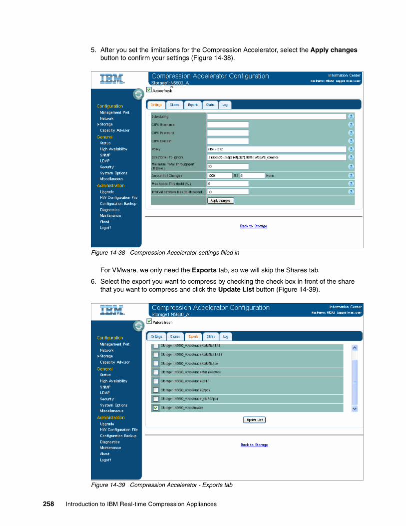
5. After you set the limitations for the Compression Accelerator, select the Apply changes button to confirm your settings (Figure 14-38).
Figure 14-38 Compression Accelerator settings filled in
For VMware, we only need the Exports tab, so we will skip the Shares tab.
6. Select the export you want to compress by checking the check box in front of the share that you want to compress and click the Update List button (Figure 14-39).
Figure 14-39 Compression Accelerator - Exports tab
258 Introduction to IBM Real-time Compression Appliances
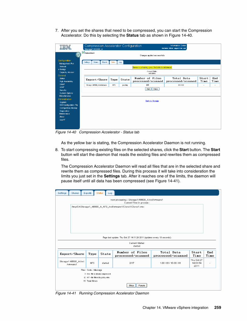
7. After you set the shares that need to be compressed, you can start the Compression Accelerator. Do this by selecting the Status tab as shown in Figure 14-40.
Figure 14-40 Compression Accelerator - Status tab
As the yellow bar is stating, the Compression Accelerator Daemon is not running.
8. To start compressing existing files on the selected shares, click the Start button. The Start button will start the daemon that reads the existing files and rewrites them as compressed files.
The Compression Accelerator Daemon will read all files that are in the selected share and rewrite them as compressed files. During this process it will take into consideration the limits you just set in the Settings tab. After it reaches one of the limits, the daemon will pause itself until all data has been compressed (see Figure 14-41).
Figure 14-41 Running Compression Accelerator Daemon
Chapter 14. VMware vSphere integration 259
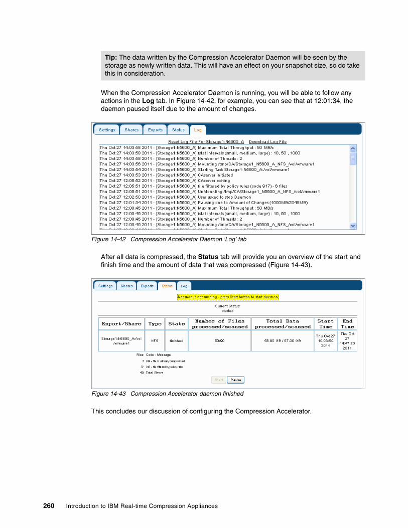
When the Compression Accelerator Daemon is running, you will be able to follow any actions in the Log tab. In Figure 14-42, for example, you can see that at 12:01:34, the daemon paused itself due to the amount of changes.
Figure 14-42 Compression Accelerator Daemon ‘Log’ tab
After all data is compressed, the Status tab will provide you an overview of the start and finish time and the amount of data that was compressed (Figure 14-43).
Figure 14-43 Compression Accelerator daemon finished
This concludes our discussion of configuring the Compression Accelerator.
Tip: The data written by the Compression Accelerator Daemon will be seen by the storage as newly written data. This will have an effect on your snapshot size, so do take this in consideration.
260 Introduction to IBM Real-time Compression Appliances
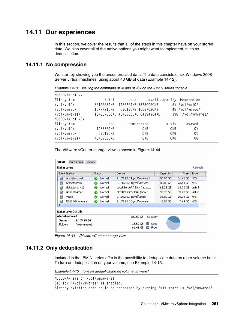
14.11 Our experiences
In this section, we cover the results that all of the steps in this chapter have on your stored data. We also cover all of the native options you might want to implement, such as deduplication.
14.11.1 No compression
We start by showing you the uncompressed data. The data consists of six Windows 2008 Server virtual machines, using about 40 GB of data (Example 14-12).
Example 14-12 Issuing the command df -k and df -Sk on the IBM N series console
N5600-A> df -kFilesystem total used avail capacity Mounted on/vol/vol0/ 25165824KB 1435764KB 23730060KB 6% /vol/vol0//vol/vmiso/ 16777216KB 690196KB 16087020KB 4% /vol/vmiso//vol/vmware1/ 104857600KB 40462636KB 64394964KB 39% /vol/vmware1/N5600-A> df -SkFilesystem used compressed a-sis %saved/vol/vol0/ 1435764KB 0KB 0KB 0%/vol/vmiso/ 690196KB 0KB 0KB 0%/vol/vmware1/ 40462636KB 0KB 0KB 0%
The VMware vCenter storage view is shown in Figure 14-44.
Figure 14-44 VMware vCenter storage view
14.11.2 Only deduplication
Included in the IBM N series offer is the possibility to deduplicate data on a per volume basis. To turn on deduplication on your volume, see Example 14-13.
Example 14-13 Turn on deduplication on volume vmware1
N5600-A> sis on /vol/vmvmware1SIS for "/vol/vmware1" is enabled.Already existing data could be processed by running "sis start -s /vol/vmware1".
Chapter 14. VMware vSphere integration 261

As stated in Example 14-13 on page 261, to start the deduplication, you have to run the command sis start -s <path-to-your-volume> to start processing the existing data on the volume (see Example 14-14 for the results).
Example 14-14 Start the deduplication process
N5600-A> sis start -s /vol/vmware1The file system will be scanned to process existing data in /vol/vmware1.This operation may initialize related existing metafiles.Are you sure you want to proceed (y/n)? yThe SIS operation for "/vol/vmware1" is started.[N5600-A: wafl.scan.start:info]: Starting SIS volume scan on volume vmware1.
You can monitor the status of the deduplication process by using the command sis status (Example 14-15).
Example 14-15 Monitoring the deduplication process
N5600-A> sis statusPath State Status Progress/vol/vmiso Enabled Idle Idle for 00:03:32/vol/vmware Enabled Idle Idle for 13:19:15/vol/vmware1 Enabled Active 11 GB ScannedN5600-A> sis statusPath State Status Progress/vol/vmiso Enabled Idle Idle for 00:08:24/vol/vmware Enabled Idle Idle for 00:02:37/vol/vmware1 Enabled Active 10 GB SearchedN5600-A> sis statusPath State Status Progress/vol/vmiso Enabled Idle Idle for 00:09:18/vol/vmware Enabled Idle Idle for 00:03:31/vol/vmware1 Enabled Active 235 MB (6%) Done
After the process is complete, we can check the results in the IBM N series console and the VMware vCenter GUI.
As shown in Example 14-16, deduplication has saved 53% of the space the virtual machines took. Instead of 40% of the volume, the files only use 18% of the volume.
Example 14-16 Issuing the command df -k and df -Sk on the N series console
N5600-A> df -kFilesystem total used avail capacity Mounted on/vol/vol0/ 25165824KB 1437136KB 23728688KB 6% /vol/vol0//vol/vmiso/ 16777216KB 690196KB 16087020KB 4% /vol/vmiso//vol/vmware1/ 104857600KB 19047572KB 85810028KB 18% /vol/vmware1/N5600-A> df -SkFilesystem used compressed a-sis %saved/vol/vol0/ 1437148KB 0KB 0KB 0%/vol/vmiso/ 690196KB 0KB 0KB 0%/vol/vmware1/ 19047572KB 0KB 21415064KB 53%
262 Introduction to IBM Real-time Compression Appliances

The VMware vCenter GUI only shows the free space, there we notice that indeed there is about 82% of free space in the volume (Figure 14-45).
Figure 14-45 VMware vCenter storage view
14.11.3 Turning on compression
When we turn on compression and run the Compression Accelerator daemon, the deduplication gains we previously had will disappear. This is due to the fact that the Compression Accelerator daemon rewrites all uncompressed data as compressed data. The storage will see this as newly written data, and thus deduplication, which is a background process, and snapshots, will be influenced (Example 14-17).
Example 14-17 Issuing the command df -k and df -Sk on the IBM N series console
N5600-A> df -kFilesystem total used avail capacity Mounted on/vol/vol0/ 25165824KB 1436852KB 23728972KB 6% /vol/vol0//vol/vmiso/ 16777216KB 690196KB 16087020KB 4% /vol/vmiso//vol/vmware1/ 104857600KB 11300908KB 93556692KB 11% /vol/vmware1/N5600-A> df -SkFilesystem used compressed a-sis %saved/vol/vol0/ 1436856KB 0KB 0KB 0%/vol/vmiso/ 690196KB 0KB 0KB 0%/vol/vmware1/ 11300908KB 0KB 12KB 0%
As you can see in Example 14-17, the saved space we used to have using deduplication has been reduced to 0%. The used space is only 11%, which is better than when only using deduplication. In the VMware storage view, it looks like Figure 14-46.
Chapter 14. VMware vSphere integration 263
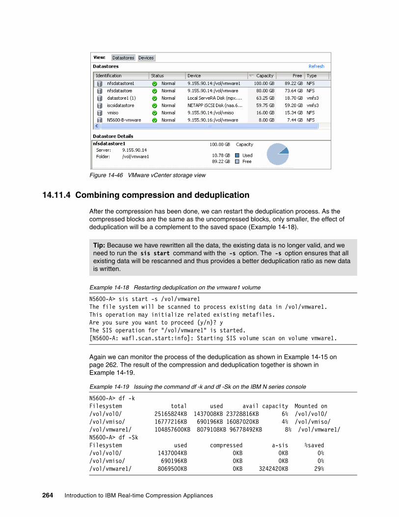
Figure 14-46 VMware vCenter storage view
14.11.4 Combining compression and deduplication
After the compression has been done, we can restart the deduplication process. As the compressed blocks are the same as the uncompressed blocks, only smaller, the effect of deduplication will be a complement to the saved space (Example 14-18).
Example 14-18 Restarting deduplication on the vmware1 volume
N5600-A> sis start -s /vol/vmware1The file system will be scanned to process existing data in /vol/vmware1.This operation may initialize related existing metafiles.Are you sure you want to proceed (y/n)? yThe SIS operation for "/vol/vmware1" is started.[N5600-A: wafl.scan.start:info]: Starting SIS volume scan on volume vmware1.
Again we can monitor the process of the deduplication as shown in Example 14-15 on page 262. The result of the compression and deduplication together is shown in Example 14-19.
Example 14-19 Issuing the command df -k and df -Sk on the IBM N series console
N5600-A> df -k Filesystem total used avail capacity Mounted on/vol/vol0/ 25165824KB 1437008KB 23728816KB 6% /vol/vol0//vol/vmiso/ 16777216KB 690196KB 16087020KB 4% /vol/vmiso//vol/vmware1/ 104857600KB 8079108KB 96778492KB 8% /vol/vmware1/N5600-A> df -Sk Filesystem used compressed a-sis %saved/vol/vol0/ 1437004KB 0KB 0KB 0%/vol/vmiso/ 690196KB 0KB 0KB 0%/vol/vmware1/ 8069500KB 0KB 3242420KB 29%
Tip: Because we have rewritten all the data, the existing data is no longer valid, and we need to run the sis start command with the -s option. The -s option ensures that all existing data will be rescanned and thus provides a better deduplication ratio as new data is written.
264 Introduction to IBM Real-time Compression Appliances
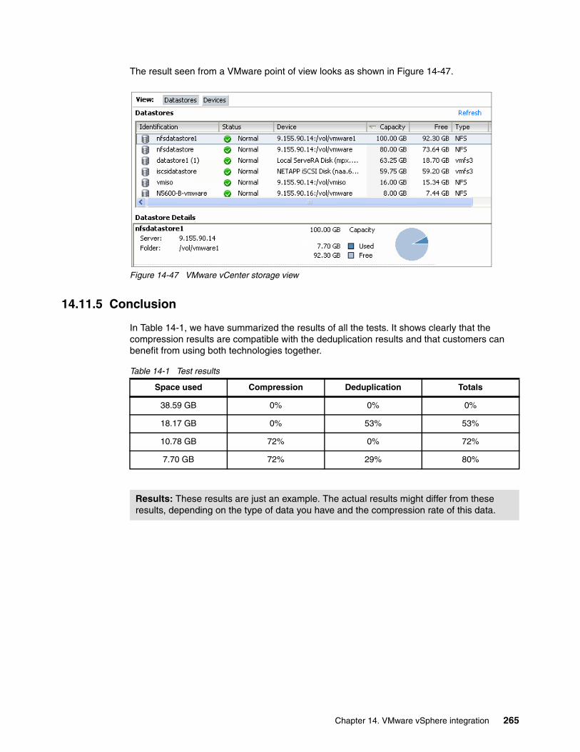
The result seen from a VMware point of view looks as shown in Figure 14-47.
Figure 14-47 VMware vCenter storage view
14.11.5 Conclusion
In Table 14-1, we have summarized the results of all the tests. It shows clearly that the compression results are compatible with the deduplication results and that customers can benefit from using both technologies together.
Table 14-1 Test results
Space used Compression Deduplication Totals
38.59 GB 0% 0% 0%
18.17 GB 0% 53% 53%
10.78 GB 72% 0% 72%
7.70 GB 72% 29% 80%
Results: These results are just an example. The actual results might differ from these results, depending on the type of data you have and the compression rate of this data.
Chapter 14. VMware vSphere integration 265

266 Introduction to IBM Real-time Compression Appliances

Chapter 15. Oracle database application integration
In this chapter, we describe Oracle database integration using RTCA. IBM and Oracle have worked over the past several years to validate Oracle products on N series storage devices and a range of server platforms.
This section also provides a practical approach on how to implement the IBM Real-time Compression Appliance when implementing an Oracle database on Red Hat Enterprise Linux (RHEL) with NFS using the N series as a storage foundation
15
© Copyright IBM Corp. 2013. All rights reserved. 267

15.1 Foundational best practices
It is important to realize that an RTCA implementation builds on the best practices that relate to three aspects. These are the NAS storage controller, NAS client platforms, and Oracle database application.
Consider the following related best practices in the deployment of the NAS environment prior to the implementation of the RTCA product:
� Best practices guidelines - IBM System Storage N series and Oracle Database 11g, Technical report NS3633-1:
https://www-304.ibm.com/partnerworld/wps/servlet/ContentHandler/whitepaper/systems/oracle/best_practice
This document describes best-practice guidelines for running Oracle Database 11g on IBM System Storage N series storage systems with platforms such as Solaris, Hewlett Packard HP/UX, IBM AIX®, Linux and Microsoft Windows. It represents the best-practice minimum requirements for deployment of Oracle on IBM System Storage N series. Intended to be a guideline of proven methods and techniques.
� Red Hat Enterprise Linux Protocol Performance Comparison with Oracle Database 11g Release 2:
http://media.netapp.com/documents/tr-3932.pdf
This technical report compares the performance of different network protocols and file systems and how they interact with Oracle Database 11g Release 2 workloads running on Red Hat Enterprise Linux 5 U4 using Gigabit Ethernet (GbE), 10GbE, 10Gb FCOE, and 4Gb/8Gb Fibre Channel (FC).
This section describes the best practices for deploying the RTCA product in Linux RHEL using an Oracle Database environment on NFS exported from N series.
268 Introduction to IBM Real-time Compression Appliances
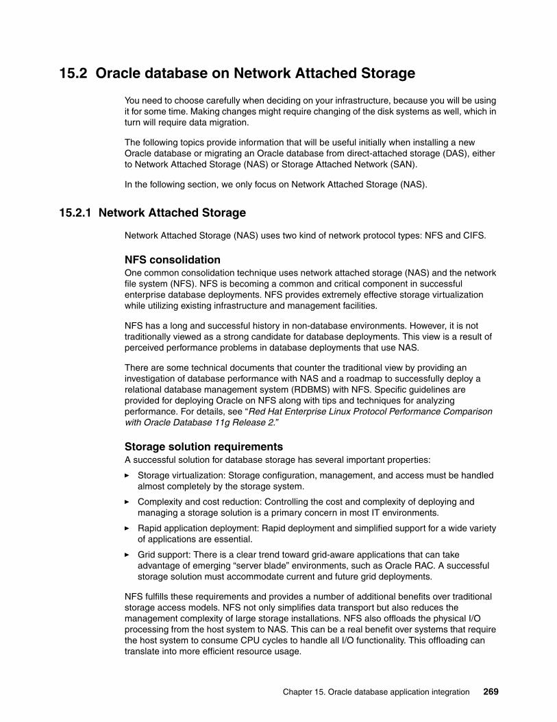
15.2 Oracle database on Network Attached Storage
You need to choose carefully when deciding on your infrastructure, because you will be using it for some time. Making changes might require changing of the disk systems as well, which in turn will require data migration.
The following topics provide information that will be useful initially when installing a new Oracle database or migrating an Oracle database from direct-attached storage (DAS), either to Network Attached Storage (NAS) or Storage Attached Network (SAN).
In the following section, we only focus on Network Attached Storage (NAS).
15.2.1 Network Attached Storage
Network Attached Storage (NAS) uses two kind of network protocol types: NFS and CIFS.
NFS consolidationOne common consolidation technique uses network attached storage (NAS) and the network file system (NFS). NFS is becoming a common and critical component in successful enterprise database deployments. NFS provides extremely effective storage virtualization while utilizing existing infrastructure and management facilities.
NFS has a long and successful history in non-database environments. However, it is not traditionally viewed as a strong candidate for database deployments. This view is a result of perceived performance problems in database deployments that use NAS.
There are some technical documents that counter the traditional view by providing an investigation of database performance with NAS and a roadmap to successfully deploy a relational database management system (RDBMS) with NFS. Specific guidelines are provided for deploying Oracle on NFS along with tips and techniques for analyzing performance. For details, see “Red Hat Enterprise Linux Protocol Performance Comparison with Oracle Database 11g Release 2.”
Storage solution requirementsA successful solution for database storage has several important properties:
� Storage virtualization: Storage configuration, management, and access must be handled almost completely by the storage system.
� Complexity and cost reduction: Controlling the cost and complexity of deploying and managing a storage solution is a primary concern in most IT environments.
� Rapid application deployment: Rapid deployment and simplified support for a wide variety of applications are essential.
� Grid support: There is a clear trend toward grid-aware applications that can take advantage of emerging “server blade” environments, such as Oracle RAC. A successful storage solution must accommodate current and future grid deployments.
NFS fulfills these requirements and provides a number of additional benefits over traditional storage access models. NFS not only simplifies data transport but also reduces the management complexity of large storage installations. NFS also offloads the physical I/O processing from the host system to NAS. This can be a real benefit over systems that require the host system to consume CPU cycles to handle all I/O functionality. This offloading can translate into more efficient resource usage.
Chapter 15. Oracle database application integration 269
15.3 Oracle, N series, and RTCA compression comparison
Several compression technologies exist for NAS storage. and Oracle itself provides a compression feature. Native compression must be evaluated before applying an additional compression technology. Each of these features has its strengths, and the best compression solution for each environment might differ.
15.3.1 Oracle Advanced Compression
In recent years, databases have experienced explosive growth in size. Oracle Database 11g addresses this issue with a new Oracle Advanced Compression feature that works with all data types (regularly structured [numbers, characters], unstructured [documents, spreadsheets, XML and other files] and backup data).
Advanced Compression in Oracle Database 11g not only reduces disk space requirements for all types of data, it also improves application performance and enhances memory and network efficiency. In addition, it can be used for any type of application without application changes.
Advanced Compression in Oracle Database 11g has the following new features:
� OLTP table compression: This feature allows structured or relational data to be compressed during all types of data manipulation operations, including regular INSERT, UPDATE, or DELETEs. This new feature leverages a sophisticated and intelligent algorithm that minimizes the compression overhead during write operations, thereby making it viable for all application workloads. Additionally, it significantly improves performance of queries by reducing disk I/O and improving memory efficiency. Previous Oracle Database releases supported compression for bulk data-loading operations commonly used for data warehousing applications. Oracle Database 11g OLTP table compression improves database performance with more effective use of memory for caching data and reduced I/O for table scans. With OLTP table compression, you can achieve twofold to threefold compression ratios with minimal processing overhead.
� Fast files deduplication: This feature is intelligent technology that eliminates duplicate copies of files stored in Oracle Database 11g. Besides reducing storage footprint, this feature also dramatically improves the performance of write and copy operations involving duplicate content.
� Fast files compression: This feature compresses the unstructured or file data stored within the database. Two levels of compression are available so you have a choice of higher compression by using additional system (CPU) resources.
� Backup data compression: The storage requirements for maintaining database backups and backup performance are directly affected by database size. To that end, advanced compression includes compression for backup data when you employ Recovery Manager (RMAN) or Oracle Data Pump for database backups.
� Network traffic compression: Advanced compression offers the capability to compress Oracle Data Guard (standby databases) redo data as Data Guard resolves redo gaps. This improves the efficiency of network utilization and speeds up gap resolution.
15.3.2 N series / Netapp compression
Netapp data compression is a software-based solution that provides transparent data compression. No application changes are required to use Netapp data compression.
270 Introduction to IBM Real-time Compression Appliances
How data compression worksNetapp data compression does not compress the entire file as a single contiguous stream of bytes. This will be prohibitively expensive when it comes to servicing small reads or overwrites from part of a file because it requires the entire file to be read from disk and uncompressed before the request can be served. This will be especially difficult on large files. To avoid this, Netapp data compression works by compressing a small group of consecutive blocks, known as a compression group. In this way, when a read or overwrite request comes in, we only need to read a small group of blocks, not the entire file. This optimizes read and overwrite performance and allows greater scalability in the size of the files being compressed.
When data compression runsNetapp data compression can be run in-line or post-process and also includes the ability to perform compression of existing data.
In-line operationsNetapp data compression can be configured as an in-line operation. In this way, as data is sent to the storage system, it is compressed in memory before being written to the disk. The advantage of this implementation is that it can reduce the amount of write I/O. This implementation option can affect your write performance and thus must not be used for performance-sensitive environments that without proper testing to understand the impact.
In order to provide the fastest throughput, in-line compression will compress most new writes but will defer some more performance-intensive compression operations to compress when the next post-process compression process is run. An example of a performance-intensive compression operation includes partial compression group writes and overwrites.
Post-process operationsNetapp data compression includes the ability to run post-process compression. Post-process compression uses the same schedule as deduplication utilizes. If compression is enabled when the sis schedule initiates a post-process operation, it runs compression first, followed by deduplication. It includes the ability to compress data that existed on disk prior to enabling compression.
If both in-line and post-process compression are enabled, then post-process compression will try to compress only blocks that are not already compressed. This includes blocks that were bypassed by in-line compression such as small partial compression group overwrites.
15.3.3 RTCA compression
RTCA implementation has already been described in detail in the previous chapters.
Intuitively, inserting a compression appliance in the data path might seem to introduce risk of negatively impacting performance. In reality, customer experience and performance benchmarks illustrate that storage system efficiency is increased, and performance is either maintained, or even increased, when the IBM Real-time Compression Appliance is utilized.
15.3.4 Comparison between compression features
Each compression feature will have pluses and minuses that you need to take into consideration before deciding which one is the more suitable to implement. A brief comparison can be seen in Table 15-1.
Chapter 15. Oracle database application integration 271
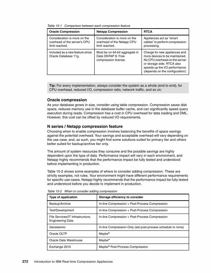
Table 15-1 Comparison between each compression feature
Oracle compressionAs your database grows in size, consider using table compression. Compression saves disk space, reduces memory use in the database buffer cache, and can significantly speed query execution during reads. Compression has a cost in CPU overhead for data loading and DML. However, this cost can be offset by reduced I/O requirements.
N series / Netapp compression featureChoosing when to enable compression involves balancing the benefits of space savings against the potential overhead. Your savings and acceptable overhead will vary depending on the use case, and, as such, you might find some solutions suited for primary tier and others better suited for backup/archive tier only.
The amount of system resources they consume and the possible savings are highly dependent upon the type of data. Performance impact will vary in each environment, and Netapp highly recommends that the performance impact be fully tested and understood before implementing in production.
Table 15-2 shows some examples of where to consider adding compression. These are strictly examples, not rules. Your environment might have different performance requirements for specific use cases. Netapp highly recommends that the performance impact be fully tested and understood before you decide to implement in production.
Table 15-2 When to consider adding compression
Oracle Compression Netapp Compression RTCA
Consideration is more on the overhead of the server’s CPU limit reached.
Consideration is more on the overhead of the Netapp CPU limit reached.
Appliances act as “smart cables” to perform compression processing.
Included as a new feature since Oracle Database 11g.
Must be on 64-bit aggregate in Data ONTAP 8. Free compression license.
Charge for new appliances and more devices to be maintained. No CPU overhead on the server or storage side. RTCA also speeds up the I/O performance (depends on the configuration).
Tip: For every implementation, always consider the system as a whole (end to end), for CPU overhead, reduced I/O, compression ratio, network traffic, and so on.
Type of application Storage efficiency to consider
Backup/Archive In-line Compression + Post-Process Compression
Test/Development In-line Compression + Post-Process Compression
File Services/IT Infrastructure, Engineering Data
In-line Compression + Post-Process Compression
Geosiesmic In-line Compression Only (set post-process schedule to none)
Oracle OLTP Maybea
Oracle Data Warehouse Maybea
Exchange 2010 Maybea Post-Process Compression
272 Introduction to IBM Real-time Compression Appliances
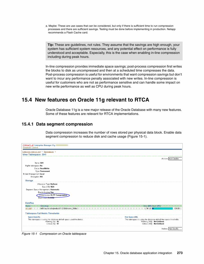
In-line compression provides immediate space savings; post-process compression first writes the blocks to disk as uncompressed and then at a scheduled time compresses the data. Post-process compression is useful for environments that want compression savings but don‘t want to incur any performance penalty associated with new writes. In-line compression is useful for customers who are not as performance sensitive and can handle some impact on new write performance as well as CPU during peak hours.
15.4 New features on Oracle 11g relevant to RTCA
Oracle Database 11g is a new major release of the Oracle Database with many new features. Some of these features are relevant for RTCA implementations.
15.4.1 Data segment compression
Data compression increases the number of rows stored per physical data block. Enable data segment compression to reduce disk and cache usage (Figure 15-1).
Figure 15-1 Compression on Oracle tablespace
a. Maybe: These are use cases that can be considered, but only if there is sufficient time to run compression processes and there are sufficient savings. Testing must be done before implementing in production. Netapp recommends a Flash Cache card.
Tip: These are guidelines, not rules. They assume that the savings are high enough, your system has sufficient system resources, and any potential effect on performance is fully understood and acceptable. Especially, this is the case when enabling in-line compression including during peak hours.
Chapter 15. Oracle database application integration 273

You can specify compression for a tablespace, a table, or a partition. If specified at the tablespace level, then all tables created in that tablespace are compressed by default. See Figure 15-1 on page 273 for a example of Oracle Tablespace Compression.
15.4.2 Oracle compression options
Here is a list of Oracle compression options:
� No Compression� Basic Compression� OLTP Compression� Data Warehouse Compression� Online Archival Compression
See Figure 15-2 for a display of compression options.
Figure 15-2 Oracle compression options for tablespace
15.5 Best practices
This section provides information for Linux on Oracle Database using NFS on N series storage.
15.5.1 Storage network configuration
Using jumbo frames can improve performance in environments where Linux NFS clients and NAS systems are together on an unrouted network. Be sure to consult the command reference for each switch to make sure it is capable of handling jumbo frames. If possible, set the Maximum Transmission Unit (MTU) size of 9,000 for all storage interfaces on the host, for all interfaces on the N series controllers, and for the ports involved on the switch.
If possible, to take advantage of all 1 GbE interfaces, the best practice is to create two separate LACP bonds. Each bond contains two individual interfaces. Connect these interfaces to a single ifgrp (vif), which bonds four 1 GbE interfaces on the storage side.
274 Introduction to IBM Real-time Compression Appliances

15.5.2 NFS mount options for Oracle databases
Table 15-3 and Table 15-4 show the mount options for Oracle databases on N series using NFS.
Table 15-3 Oracle 10g (R1,R2), 11g RAC with Oracle CRS clusterware
Table 15-4 Oracle 10g (R1,R2) non-RAC, Single Instance (SI)
[common] = rw,bg,hard,rsize=32768,wsize=32768,vers=3 [common] = These mount options must be used in addition to the ones in the matrix above.
OS Mount options for binaries
Mount options for Oracle data files
Mount options for OCR and CRS voting files
Mount options for ADR HOME (11g only)
init.ora parameters
Solaris [common], noac,nointr, proto=tcp, suid
[common], forcedirectio, noac,nointr, proto=tcp,suid
[common], forcedirectio, noac,nointr, proto=tcp
[common], actimeo=0, nointr, proto=tcp, suid
filesystemio _options= setall
AIX [common], nointr,timeo=600, proto=tcp
[common], cio,noac, nointr,timeo=600, proto=tcp
[common], cio,intr,noac, timeo=600, proto=tcp
[common], nointr, timeo=600, proto=tcp
filesystemio _options= setall
HPU [common], noac,nointr, timeo=600, proto=tcp,suid
[common], forcedirectio, noac,nointr, timeo=600, proto=tcp, suid
[common], forcedirectio, noac,nointr, timeo=600, proto=tcp,suid
[common], actimeo=0, nointr, timeo=600, proto=tcp, suid
filesystemio _options= setall
Linux [common], actimeo=0, nointr, suid, timeo=600, tcp
[common], actimeo=0, nointr, suid, timeo=600, tcp
[common], actimeo=0, nointr, suid, timeo=600, tcp
[common], actimeo=0, nointr, suid, timeo=600, tcp
filesystemio _options= setall or directio
OS Mount options for binaries
Mount options for Oracle data files
Mount options for OCR and CRS voting files
Mount options for ADR HOME (11g only)
init.ora parameters
Solaris [common], nointr, proto=tcp, suid
[common], [forcedirectio or llock], nointr, proto=tcp, suid
N/A [common], nointr, proto=tcp suid
filesystemio _options= setall
AIX [common], intr,timeo=600, proto=tcp
[common], cio,intr, timeo=600, proto=tcp
N/A [common], nointr, timeo=600, proto=tcp
filesystemio _options= setall
HPU [common], nointr,timeo=600, proto=tcp
[common], nointr, timeo=600, proto=tcp, suid
N/A [common], nointr, timeo=600, proto=tcp, suid
filesystemio _options= setall
Linux [common], nointr,timeo=600, tcp
[common], nointr, timeo=600, tcp
N/A [common], nointr,suid, timeo=600, tcp
filesystemio _options= setall or directio
Chapter 15. Oracle database application integration 275
For read/write size for all UNIX based operating systems, rsize=65536 and wsize=65536 can also be used. Using these settings enabled us to take better advantage of larger TCP window sizes, which are now available on the storage controllers.
15.5.3 Data ONTAP tuning options
There are several tuning options that must be implemented if using N series or Netapp NAS.
This increases the size of the TCP receive window for NFS. The TCP receive window on the client must be adjusted to match the size of the NetApp controller because TCP reduces the size of the larger TCP receive window to match the size of the smaller TCP window:
nfs.tcp.recvwindowsize 262144
We found that it was necessary to increase the default value of 26,280 to realize the performance increase of jumbo frames.
nfs.tcp.xfersize 65536
This is the default setting for this option. Make sure that it is not reduced. This option controls the TCP transmit window size for NFS.
setflag wafl_max_write_alloc_blocks 256
We set one additional flag in the /etc/rc file of each storage system. This flag optimizes the WAFL (Write Anywhere File Layout) on-disk data layout.
15.5.4 LINUX tuning options
Here are some Linux tuning parameters that must be implemented:
sunrpc.tcp_slot_table_entries = 128
Increasing this parameter from the default of 16 to the maximum of 128 increases the number of in-flight Remote Procedure Calls (I/Os).
Be sure to edit /etc/init.d/netfs to call /sbin/sysctl –p in the first line of the script so that sunrpc.tcp_slot_table_entries is set before NFS mounts any file systems. If NFS mounts the file systems before this parameter is set, the default value of 16 is implemented.
276 Introduction to IBM Real-time Compression Appliances
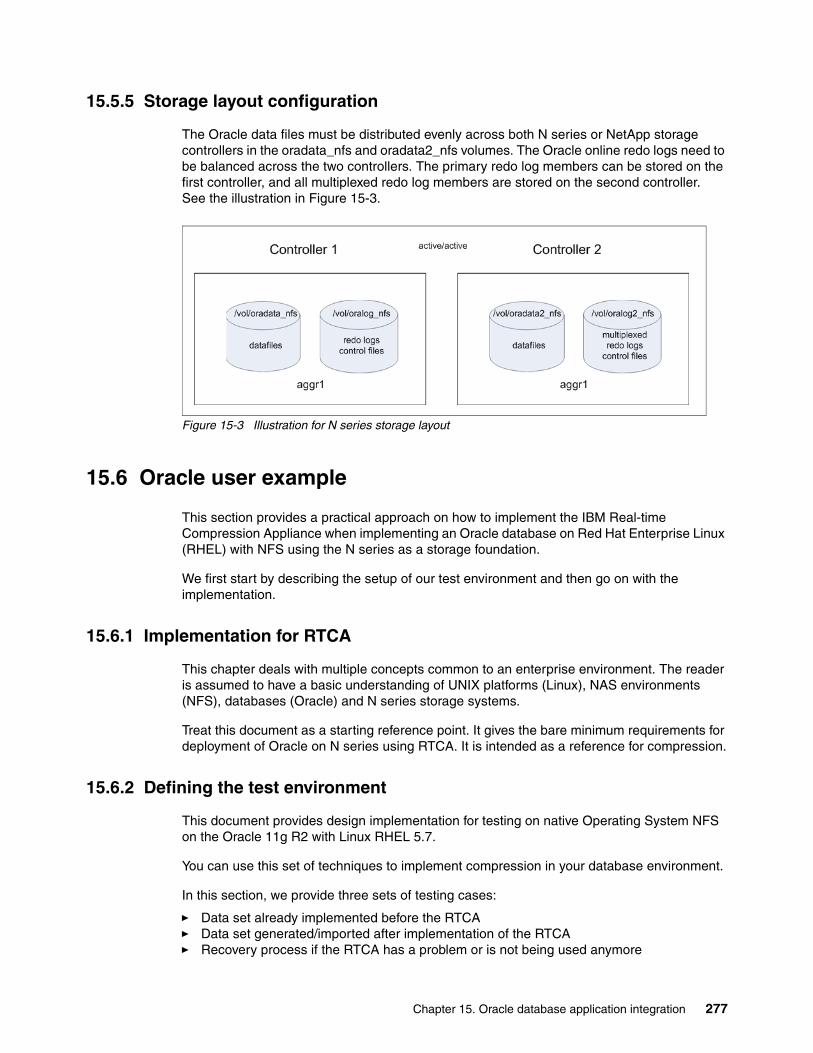
15.5.5 Storage layout configuration
The Oracle data files must be distributed evenly across both N series or NetApp storage controllers in the oradata_nfs and oradata2_nfs volumes. The Oracle online redo logs need to be balanced across the two controllers. The primary redo log members can be stored on the first controller, and all multiplexed redo log members are stored on the second controller. See the illustration in Figure 15-3.
Figure 15-3 Illustration for N series storage layout
15.6 Oracle user example
This section provides a practical approach on how to implement the IBM Real-time Compression Appliance when implementing an Oracle database on Red Hat Enterprise Linux (RHEL) with NFS using the N series as a storage foundation.
We first start by describing the setup of our test environment and then go on with the implementation.
15.6.1 Implementation for RTCA
This chapter deals with multiple concepts common to an enterprise environment. The reader is assumed to have a basic understanding of UNIX platforms (Linux), NAS environments (NFS), databases (Oracle) and N series storage systems.
Treat this document as a starting reference point. It gives the bare minimum requirements for deployment of Oracle on N series using RTCA. It is intended as a reference for compression.
15.6.2 Defining the test environment
This document provides design implementation for testing on native Operating System NFS on the Oracle 11g R2 with Linux RHEL 5.7.
You can use this set of techniques to implement compression in your database environment.
In this section, we provide three sets of testing cases:
� Data set already implemented before the RTCA� Data set generated/imported after implementation of the RTCA� Recovery process if the RTCA has a problem or is not being used anymore
Chapter 15. Oracle database application integration 277

Generally, these are the steps we implement:
1. Install Oracle database. Configure the datafile using NFS export to the storage. Prepare and populate it with generated data. The data is generated using data model for TPC-H with scale 20. For existing customers that already use an Oracle database, you usually have your own data sets to simulate the characteristics of your business process.
We also generate some data that is using Oracle OLTP Compression.
2. Implement non-disruptive RTCA with transparent mode. NFS export configured on the RTCA with NNC (No New Compression). This will make sure that nothing changed on the transferred data (Without Compression).
3. Activate compression. This can be either using the Compression Accelerator to compress existing data or fresh loaded data.
The Real-time Compression Appliance (RTCA) software compresses new files written through it to a share or export that is configured as compressed in the compression filters list. If a file exists in this share or export prior to the activation of export filters, it is not automatically compressed. To compress such files, the software's Compression Accelerator utility must be used. If you choose to leave it uncompressed, it will remain uncompressed even when updated through the software.
4. Manually recover the data if it had some problem or you decide to run without the RTCA.
Environment:
� IBM xSeries® x3650-m2 running on Linux RHEL 5.7.
We adjust Linux OS settings for Oracle. For production database systems, Oracle recommends to tune these values to optimize the performance of the system. See the operating system documentation for more information about tuning kernel parameters.
Verify that the kernel parameters shown in Table 15-5 are set to values greater than or equal to the recommended value shown.
Table 15-5 Linux kernel parameter
Tip: Any Oracle datafile that was created before activating RTCA will stay uncompressed. Optionally, you can enable the Compression Accelerator for a particular export path, or migrate to a new datafile.
Parameter Value File
semmslsemmnssemopmsemmni
25032000100128
/proc/sys/kernel/sem
shmall 2097152 /proc/sys/kernel/shmall
shmmax Half the size of physical memory (in bytes). For more information, see the My Oracle Support Note 567506.1.
/proc/sys/kernel/shmmax
shmmni 4096 /proc/sys/kernel/shmmni
file-max 6815744 /proc/sys/fs/file-max
ip_local_port_range Minimum: 9000Maximum: 65500
/proc/sys/net/ipv4/ip_local_port_range
278 Introduction to IBM Real-time Compression Appliances

To improve the performance of the software on Linux systems, we also increase the following shell limits for the Oracle user as shown in Table 15-6.
Table 15-6 Setting shell limits for the Oracle user
Setting the right NFS mount options can significantly affect both performance and reliability of the I/O subsystem. N series recommended mount options have been thoroughly tested and approved by both N series and Oracle as shown in Table 15-7.
Table 15-7 Mount options
� Oracle libraries and binaries located on local file system. Oracle datafile, archive-log, and redo-log configured using NFS exported from N5600 storage. See Table 15-8 for Oracle layout details.
Table 15-8 Oracle layout
rmem_default 4194304 /proc/sys/net/core/rmem_default
rmem_max 4194304 /proc/sys/net/core/rmem_max
wmem_default 262144 /proc/sys/net/core/wmem_default
wmem_max 1048576 /proc/sys/net/core/wmem_max
aio-max-nr 1048576 /proc/sys/fs/aio-max-nr
Tip: If the current value for any parameter is higher than the value listed in this table, then do not change the value of that parameter.
Shell Limit Item in limits.conf Hard limit
Maximum number of open file descriptors nofile 65536
Maximum number of processes available to a single user nproc 16384
NFS location Mount options
Mount options for binaries rw,bg,hard,rsize=65536,wsize=65536,vers=3,nointr,timeo=600, tcp
Mount options for Oracle datafiles
rw,bg,hard,rsize=65536,wsize=65536,vers=3,nointr,timeo=600, tcp
Mount options for ADR_HOME (11g only)
rw,bg,hard,rsize=65536,wsize=65536,vers=3,nointr,suid, timeo=600, tcp
init.ora parameters filesystemio _options=setall or directio
Type of Files Description Mount point Location
ORACLE_BASE /u01/app/oracle local filesystem
ORACLE_HOME Oracle libraries and binaries
/u01/app/oracle/11.2.0/dbs
Local filesystem
Data files Oracle Database datafiles
/export/datafile/<tablespace>/
NFS N series Storage
Parameter Value File
Chapter 15. Oracle database application integration 279
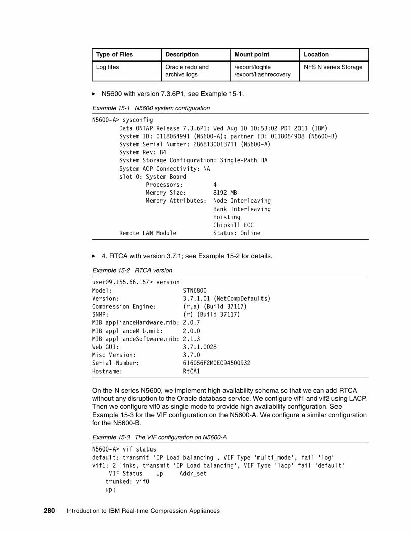
� N5600 with version 7.3.6P1, see Example 15-1.
Example 15-1 N5600 system configuration
N5600-A> sysconfig Data ONTAP Release 7.3.6P1: Wed Aug 10 10:53:02 PDT 2011 (IBM) System ID: 0118054991 (N5600-A); partner ID: 0118054908 (N5600-B) System Serial Number: 2868130013711 (N5600-A) System Rev: B4 System Storage Configuration: Single-Path HA System ACP Connectivity: NA slot 0: System Board Processors: 4 Memory Size: 8192 MB Memory Attributes: Node Interleaving Bank Interleaving Hoisting Chipkill ECC Remote LAN Module Status: Online
� 4. RTCA with version 3.7.1; see Example 15-2 for details.
Example 15-2 RTCA version
[email protected]> versionModel: STN6800Version: 3.7.1.01 (NetCompDefaults)Compression Engine: (r,a) (Build 37117)SNMP: (r) (Build 37117)MIB applianceHardware.mib: 2.0.7MIB applianceMib.mib: 2.0.0MIB applianceSoftware.mib: 2.1.3Web GUI: 3.7.1.0028Misc Version: 3.7.0Serial Number: 6I6056F2M0EC94500932Hostname: RtCA1
On the N series N5600, we implement high availability schema so that we can add RTCA without any disruption to the Oracle database service. We configure vif1 and vif2 using LACP. Then we configure vif0 as single mode to provide high availability configuration. See Example 15-3 for the VIF configuration on the N5600-A. We configure a similar configuration for the N5600-B.
Example 15-3 The VIF configuration on N5600-A
N5600-A> vif statusdefault: transmit 'IP Load balancing', VIF Type 'multi_mode', fail 'log'vif1: 2 links, transmit 'IP Load balancing', VIF Type 'lacp' fail 'default' VIF Status Up Addr_set trunked: vif0 up:
Log files Oracle redo and archive logs
/export/logfile/export/flashrecovery
NFS N series Storage
Type of Files Description Mount point Location
280 Introduction to IBM Real-time Compression Appliances
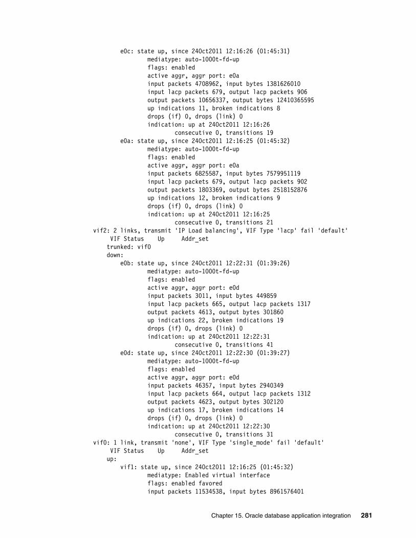
e0c: state up, since 24Oct2011 12:16:26 (01:45:31) mediatype: auto-1000t-fd-up flags: enabled active aggr, aggr port: e0a input packets 4708962, input bytes 1381626010 input lacp packets 679, output lacp packets 906 output packets 10656337, output bytes 12410365595 up indications 11, broken indications 8 drops (if) 0, drops (link) 0 indication: up at 24Oct2011 12:16:26 consecutive 0, transitions 19 e0a: state up, since 24Oct2011 12:16:25 (01:45:32) mediatype: auto-1000t-fd-up flags: enabled active aggr, aggr port: e0a input packets 6825587, input bytes 7579951119 input lacp packets 679, output lacp packets 902 output packets 1803369, output bytes 2518152876 up indications 12, broken indications 9 drops (if) 0, drops (link) 0 indication: up at 24Oct2011 12:16:25 consecutive 0, transitions 21vif2: 2 links, transmit 'IP Load balancing', VIF Type 'lacp' fail 'default' VIF Status Up Addr_set trunked: vif0 down: e0b: state up, since 24Oct2011 12:22:31 (01:39:26) mediatype: auto-1000t-fd-up flags: enabled active aggr, aggr port: e0d input packets 3011, input bytes 449859 input lacp packets 665, output lacp packets 1317 output packets 4613, output bytes 301860 up indications 22, broken indications 19 drops (if) 0, drops (link) 0 indication: up at 24Oct2011 12:22:31 consecutive 0, transitions 41 e0d: state up, since 24Oct2011 12:22:30 (01:39:27) mediatype: auto-1000t-fd-up flags: enabled active aggr, aggr port: e0d input packets 46357, input bytes 2940349 input lacp packets 664, output lacp packets 1312 output packets 4623, output bytes 302120 up indications 17, broken indications 14 drops (if) 0, drops (link) 0 indication: up at 24Oct2011 12:22:30 consecutive 0, transitions 31vif0: 1 link, transmit 'none', VIF Type 'single_mode' fail 'default' VIF Status Up Addr_set up: vif1: state up, since 24Oct2011 12:16:25 (01:45:32) mediatype: Enabled virtual interface flags: enabled favored input packets 11534538, input bytes 8961576401
Chapter 15. Oracle database application integration 281
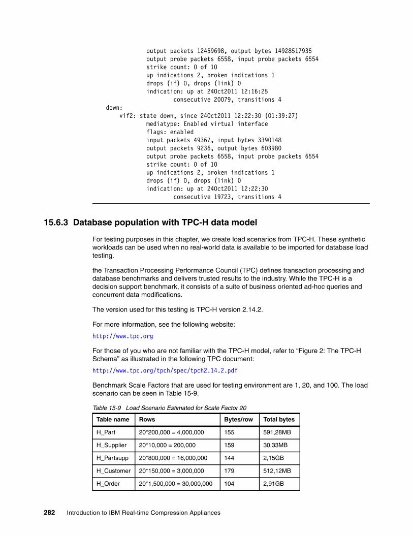
output packets 12459698, output bytes 14928517935 output probe packets 6558, input probe packets 6554 strike count: 0 of 10 up indications 2, broken indications 1 drops (if) 0, drops (link) 0 indication: up at 24Oct2011 12:16:25 consecutive 20079, transitions 4 down: vif2: state down, since 24Oct2011 12:22:30 (01:39:27) mediatype: Enabled virtual interface flags: enabled input packets 49367, input bytes 3390148 output packets 9236, output bytes 603980 output probe packets 6558, input probe packets 6554 strike count: 0 of 10 up indications 2, broken indications 1 drops (if) 0, drops (link) 0 indication: up at 24Oct2011 12:22:30 consecutive 19723, transitions 4
15.6.3 Database population with TPC-H data model
For testing purposes in this chapter, we create load scenarios from TPC-H. These synthetic workloads can be used when no real-world data is available to be imported for database load testing.
the Transaction Processing Performance Council (TPC) defines transaction processing and database benchmarks and delivers trusted results to the industry. While the TPC-H is a decision support benchmark, it consists of a suite of business oriented ad-hoc queries and concurrent data modifications.
The version used for this testing is TPC-H version 2.14.2.
For more information, see the following website:
http://www.tpc.org
For those of you who are not familiar with the TPC-H model, refer to “Figure 2: The TPC-H Schema” as illustrated in the following TPC document:
http://www.tpc.org/tpch/spec/tpch2.14.2.pdf
Benchmark Scale Factors that are used for testing environment are 1, 20, and 100. The load scenario can be seen in Table 15-9.
Table 15-9 Load Scenario Estimated for Scale Factor 20
Table name Rows Bytes/row Total bytes
H_Part 20*200,000 = 4,000,000 155 591,28MB
H_Supplier 20*10,000 = 200,000 159 30,33MB
H_Partsupp 20*800,000 = 16,000,000 144 2,15GB
H_Customer 20*150,000 = 3,000,000 179 512,12MB
H_Order 20*1,500,000 = 30,000,000 104 2,91GB
282 Introduction to IBM Real-time Compression Appliances

15.6.4 Generated data set
In this testing environment, we generate data set using the tool dbgen provided from the TPC website. Data generated using TPC-H data sets can be seen in Example 15-4. Each tablespace only contains one Oracle datafile.
Example 15-4 Tablespace created for compression testing
SQL> select * from v$tablespace;
TS# NAME INC BIG FLA ENC---------- ------------------------------ --- --- --- --- 0 SYSTEM YES NO YES 1 SYSAUX YES NO YES 2 UNDOTBS1 YES NO YES 4 USERS YES NO YES 3 TEMP NO NO YES 6 EXAMPLE YES NO YES 14 SH4 YES NO YES 9 SH YES NO YES 12 SH3 YES NO YES 8 SOE YES NO YES 7 CCDATA YES YES YES
TS# NAME INC BIG FLA ENC---------- ------------------------------ --- --- --- --- 15 SH5 YES NO YES
12 rows selected.
SQL> select tablespace_name,file_name from dba_data_files;
TABLESPACE_NAME------------------------------FILE_NAME--------------------------------------------------------------------------------USERS/u01/app/oracle/oradata/orcl/users01.dbf
UNDOTBS1/u01/app/oracle/oradata/orcl/undotbs01.dbf
SYSAUX/u01/app/oracle/oradata/orcl/sysaux01.dbf
H_Lineitem 20*6,000,000 = 120,000,000 112 12,52GB
H_Nation 25 128 3,13KB
H_Region 5 124 620
Table name Rows Bytes/row Total bytes
Chapter 15. Oracle database application integration 283
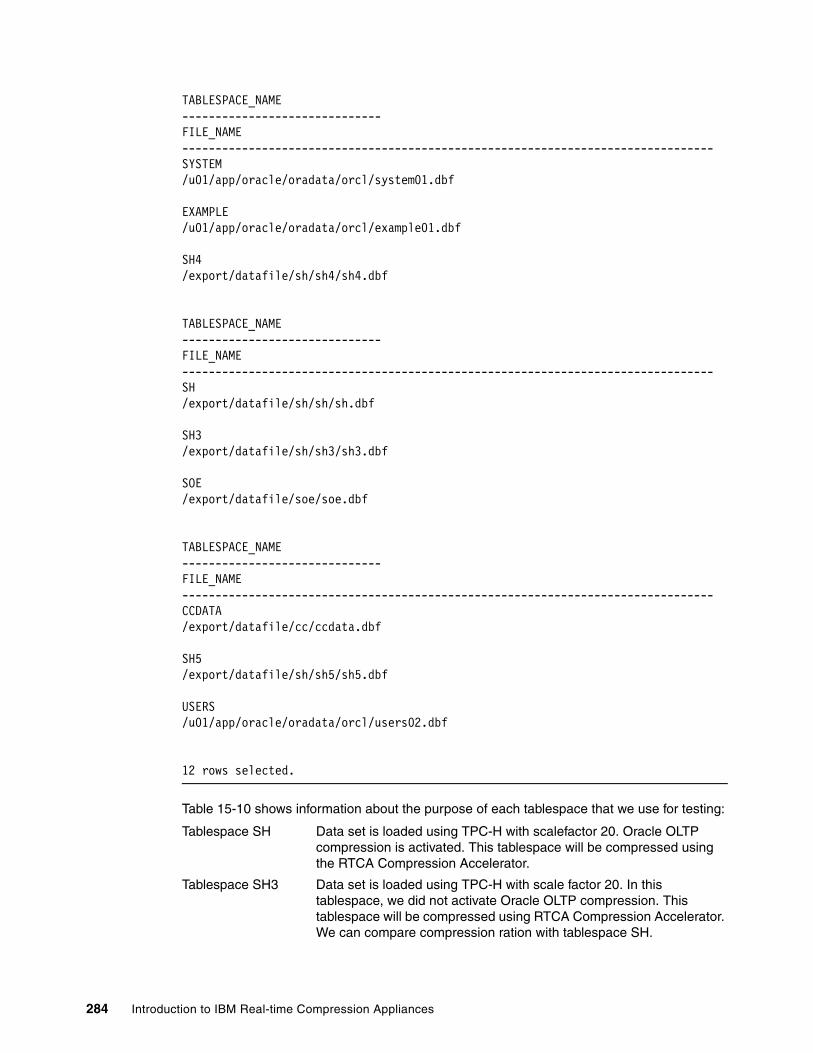
TABLESPACE_NAME------------------------------FILE_NAME--------------------------------------------------------------------------------SYSTEM/u01/app/oracle/oradata/orcl/system01.dbf
EXAMPLE/u01/app/oracle/oradata/orcl/example01.dbf
SH4/export/datafile/sh/sh4/sh4.dbf
TABLESPACE_NAME------------------------------FILE_NAME--------------------------------------------------------------------------------SH/export/datafile/sh/sh/sh.dbf
SH3/export/datafile/sh/sh3/sh3.dbf
SOE/export/datafile/soe/soe.dbf
TABLESPACE_NAME------------------------------FILE_NAME--------------------------------------------------------------------------------CCDATA/export/datafile/cc/ccdata.dbf
SH5/export/datafile/sh/sh5/sh5.dbf
USERS/u01/app/oracle/oradata/orcl/users02.dbf
12 rows selected.
Table 15-10 shows information about the purpose of each tablespace that we use for testing:
Tablespace SH Data set is loaded using TPC-H with scalefactor 20. Oracle OLTP compression is activated. This tablespace will be compressed using the RTCA Compression Accelerator.
Tablespace SH3 Data set is loaded using TPC-H with scale factor 20. In this tablespace, we did not activate Oracle OLTP compression. This tablespace will be compressed using RTCA Compression Accelerator. We can compare compression ration with tablespace SH.
284 Introduction to IBM Real-time Compression Appliances
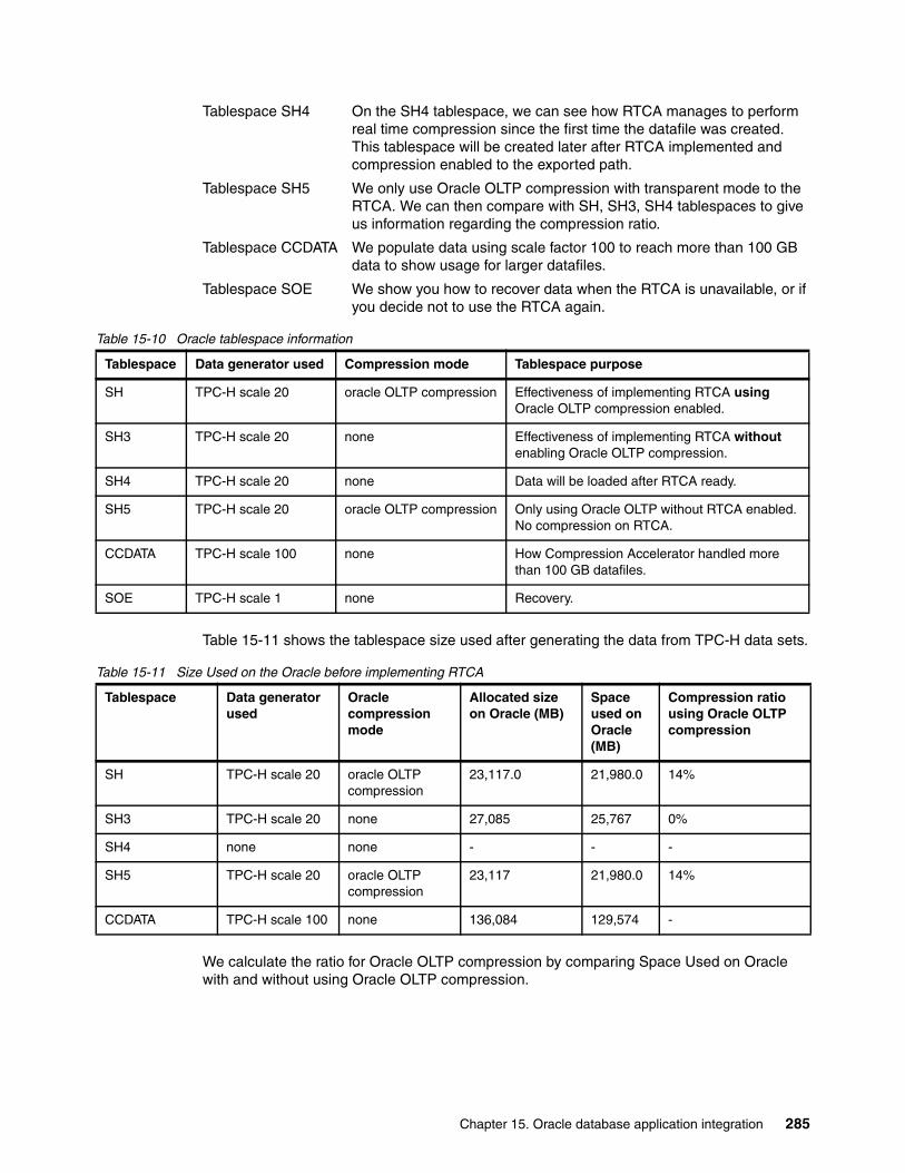
Tablespace SH4 On the SH4 tablespace, we can see how RTCA manages to perform real time compression since the first time the datafile was created. This tablespace will be created later after RTCA implemented and compression enabled to the exported path.
Tablespace SH5 We only use Oracle OLTP compression with transparent mode to the RTCA. We can then compare with SH, SH3, SH4 tablespaces to give us information regarding the compression ratio.
Tablespace CCDATA We populate data using scale factor 100 to reach more than 100 GB data to show usage for larger datafiles.
Tablespace SOE We show you how to recover data when the RTCA is unavailable, or if you decide not to use the RTCA again.
Table 15-10 Oracle tablespace information
Table 15-11 shows the tablespace size used after generating the data from TPC-H data sets.
Table 15-11 Size Used on the Oracle before implementing RTCA
We calculate the ratio for Oracle OLTP compression by comparing Space Used on Oracle with and without using Oracle OLTP compression.
Tablespace Data generator used Compression mode Tablespace purpose
SH TPC-H scale 20 oracle OLTP compression Effectiveness of implementing RTCA using Oracle OLTP compression enabled.
SH3 TPC-H scale 20 none Effectiveness of implementing RTCA without enabling Oracle OLTP compression.
SH4 TPC-H scale 20 none Data will be loaded after RTCA ready.
SH5 TPC-H scale 20 oracle OLTP compression Only using Oracle OLTP without RTCA enabled. No compression on RTCA.
CCDATA TPC-H scale 100 none How Compression Accelerator handled more than 100 GB datafiles.
SOE TPC-H scale 1 none Recovery.
Tablespace Data generator used
Oracle compression mode
Allocated size on Oracle (MB)
Space used on Oracle (MB)
Compression ratio using Oracle OLTP compression
SH TPC-H scale 20 oracle OLTP compression
23,117.0 21,980.0 14%
SH3 TPC-H scale 20 none 27,085 25,767 0%
SH4 none none - - -
SH5 TPC-H scale 20 oracle OLTP compression
23,117 21,980.0 14%
CCDATA TPC-H scale 100 none 136,084 129,574 -
Chapter 15. Oracle database application integration 285

15.6.5 Checking the capacity used for the Oracle database
The majority of Oracle database size comes from the datafiles. We can check from datafiles to see individual file size and also how much size was already allocated for data. Later on we can manage to shrink back / reclaim the file size after doing some major changes that involve deleting the data.
To find out how big the database is, we can do the following calculation:
database size = sum (datafile) + redo logs + archive logs
If the database is in archive log mode, we add archive logs, as this also normally consumes space also. In Example 15-5, we can check how big our database is.
Example 15-5 Check database size
SQL> select sum(bytes)/1024/1024 from dba_data_files;
SUM(BYTES)/1024/1024-------------------- 257306
SQL> select sum(bytes)/1024/1024 from v$log;
SUM(BYTES)/1024/1024-------------------- 150
SQL> select sum(space_used)/1024/1024 from v$recovery_file_dest;
SUM(SPACE_USED)/1024/1024------------------------- 134524.639
We can achieve a great compression ratio when enabling the compression mode on the archive log mount point. As for the simplicity of this project, we only calculate the Oracle datafiles as measurement for compression ratio.
286 Introduction to IBM Real-time Compression Appliances
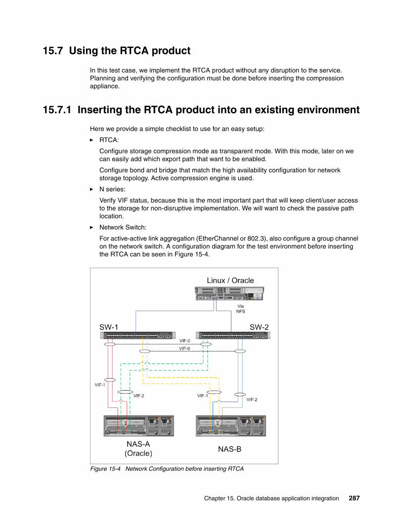
15.7 Using the RTCA product
In this test case, we implement the RTCA product without any disruption to the service. Planning and verifying the configuration must be done before inserting the compression appliance.
15.7.1 Inserting the RTCA product into an existing environment
Here we provide a simple checklist to use for an easy setup:
� RTCA:
Configure storage compression mode as transparent mode. With this mode, later on we can easily add which export path that want to be enabled.
Configure bond and bridge that match the high availability configuration for network storage topology. Active compression engine is used.
� N series:
Verify VIF status, because this is the most important part that will keep client/user access to the storage for non-disruptive implementation. We will want to check the passive path location.
� Network Switch:
For active-active link aggregation (EtherChannel or 802.3), also configure a group channel on the network switch. A configuration diagram for the test environment before inserting the RTCA can be seen in Figure 15-4.
Figure 15-4 Network Configuration before inserting RTCA
Chapter 15. Oracle database application integration 287

After finishing with the setup preparations for the solution, we are ready to insert the RTCA as a “smart cable”:
1. Unplug passive cables on the N series. Reroute those cables to the network switch (pre-configured ports if active-active link aggregation), and then plug additional cables from the RTCA to the network switch. See Figure 15-5.
Figure 15-5 Reroute passive VIF
2. Verify that all traffic from the database server is still OK. Verify either from the alert log if the database still up and running, and also from Linux /var/log/messages if there is NFS time out error detected. Verify also the VIF status on the N series.
3. Configure storage on RTCA as transparent mode (see Figure 15-6).
Figure 15-6 Add storage as transparent mode
288 Introduction to IBM Real-time Compression Appliances
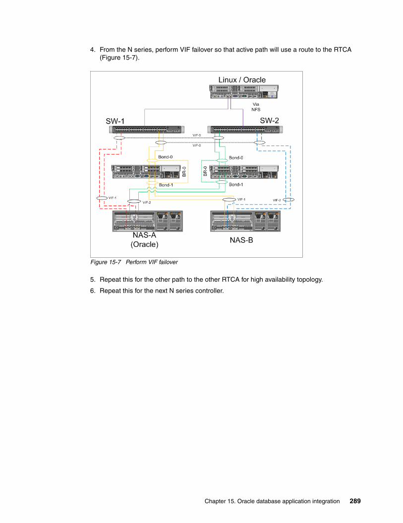
4. From the N series, perform VIF failover so that active path will use a route to the RTCA (Figure 15-7).
Figure 15-7 Perform VIF failover
5. Repeat this for the other path to the other RTCA for high availability topology.
6. Repeat this for the next N series controller.
Chapter 15. Oracle database application integration 289

The network topology after inserting the RTCA can be seen in Figure 15-8.
Figure 15-8 Network topology after inserting RTCA
The physical activities are already done. After this step, any I/O request from the host client to the N series will reroute to the RTCA in transparent mode (uncompress).
15.7.2 Enabling compression on the RTCA
As the storage is already configured in transparent mode, next we configure each export path on the N series and RTCA.
On the N series, for each exported path that needs compression enabled, add all the RTCA bridge IP addresses for read/write access. For the Compression Accelerator to work, also add all RTCA bridge IP addresses for root access.
Example 15-6 is an example of one exported path that we add for the bridge IP address for read/write and root access. 9.155.113.233 is for the Linux/Oracle Server. 9.155.90.170-173 are for bridge IP addresses.
Example 15-6 Specifying exportfs access permission
/vol/oracle/datafile/sh/sh4 -sec=sys,rw=9.155.90.173:9.155.90.172:9.155.113.233:9.155.90.171:9.155.90.170,root=9.155.90.173:9.155.90.172:9.155.90.171:9.155.113.233:9.155.90.170
All exported paths that we configured on the N series also show up on the RTCA. We select the export paths that want to be added to the compression filter. Uncheck “No new compression” so the newly created file can be compressed (see Figure 15-9).
290 Introduction to IBM Real-time Compression Appliances

Figure 15-9 Enable compression on the RTCA
We are then ready to generate data set for the SH4 tablespace with TPC-H scale factor 20.
Here are the steps that we need to take:
1. Create a new tablespace SH4 on the Oracle database with a datafile located on a compressed export path. Create a username and password that have access to the SH4 tablespace. See Example 15-9.
Example 15-7 Mount point path on Linux for SH4
9.155.90.14:/vol/oracle/datafile/sh/sh4 on /export/datafile/sh/sh4 type nfs (rw,bg,hard,rsize=32768,wsize=32768,nfsvers=3,timeo=600,tcp,nointr,addr=9.155.90.14)
2. Populate data from TPC-H scale 20 data sets (already prepared) to tablespace SH4.
The result of compression for tablespace SH4 can be seen in Example 15-8.
Example 15-8 Compression result
SQL> select bytes/1024/1024 from dba_data_files where tablespace_name='SH4';
BYTES/1024/1024--------------- 27085SQL> select sum(bytes)/1024/1024 from dba_segments where tablespace_name = 'SH4';
SUM(BYTES)/1024/1024-------------------- 25768
SQL> quitDisconnected from Oracle Database 11g Enterprise Edition Release 11.2.0.1.0 - 64bit ProductionWith the Partitioning, OLAP, Data Mining and Real Application Testing options[root@x3650-m2-84 sh4]# pwd/export/datafile/sh/sh4[root@x3650-m2-84 sh4]# du -m1 ./.snapshot27086 .[root@x3650-m2-84 sh4]# pwd
Allocated size seen on oracle datafile
Space that already used by Oracle
Space seen on Linux mount pointthat served for Orace datafile
Space seen on mount point withtransparant path mode
Chapter 15. Oracle database application integration 291

/mnt/oracle/datafile/sh/sh4[root@x3650-m2-84 sh4]# du -m10188 .[root@x3650-m2-84 sh4]#
15.7.3 Compression accelerator
The Compression Accelerator supports various configuration parameters for scheduling, throttling, and policy-based file compression that you can use to fine-tune the process. In this section, we test the Compression Accelerator on an already populated datafile.
Use these steps to enable the Compression Accelerator for datafile SH:
1. Add the compression filter to the exported path. See Figure 15-10.
Figure 15-10 Add SH to compression filter
2. Select the exported path list when configuring the Compression Accelerator. See Figure 15-11.
Figure 15-11 Select export path on Compression Accelerator menu
Tip: In order to check real space used on the storage, for RTCA 3.7, temporarily create another export path in transparent mode.
292 Introduction to IBM Real-time Compression Appliances

3. We start the Compression Accelerator now without any schedule (see Figure 15-12).
Figure 15-12 Start the Compression Accelerator
We also enable Compression Accelerator on the other datafile. The compression result can be seen in Table 15-12.
Table 15-12 Compression result
Compression ratio formula = 1 - (Real Space Used / Allocated size on Oracle ) * 100 %
Tablespace Data generator used
Oracle compression mode
RTCAenabled
Allocated size on Oracle (MB)
Space used on Oracle (MB)
Real space used (MB)
Compression ratio
SH TPC-H scale 20 oracle OLTP compression
compression accelerator
23,117 21,980 10,533 54.4%
SH3 TPC-H scale 20 none compression accelerator
27,085.0 25,767.0 10,144 62.5%
SH4 TPC-H scale 20 none create new tablespace
27,085 25,769 10,190 62.3%
SH5 TPC-H scale 20 oracle OLTP compression
- 23,117 21,980 23,163 0%
CCDATA TPC-H scale 100 none compression accelerator
136,084 129,574 55,047 59.5%
Chapter 15. Oracle database application integration 293
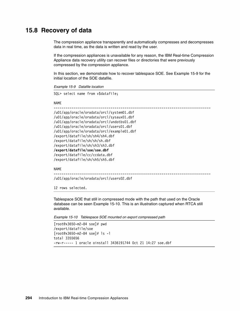
15.8 Recovery of data
The compression appliance transparently and automatically compresses and decompresses data in real time, as the data is written and read by the user.
If the compression appliances is unavailable for any reason, the IBM Real-time Compression Appliance data recovery utility can recover files or directories that were previously compressed by the compression appliance.
In this section, we demonstrate how to recover tablespace SOE. See Example 15-9 for the initial location of the SOE datafile.
Example 15-9 Datafile location
SQL> select name from v$datafile;
NAME--------------------------------------------------------------------------------/u01/app/oracle/oradata/orcl/system01.dbf/u01/app/oracle/oradata/orcl/sysaux01.dbf/u01/app/oracle/oradata/orcl/undotbs01.dbf/u01/app/oracle/oradata/orcl/users01.dbf/u01/app/oracle/oradata/orcl/example01.dbf/export/datafile/sh/sh4/sh4.dbf/export/datafile/sh/sh/sh.dbf/export/datafile/sh/sh3/sh3.dbf/export/datafile/soe/soe.dbf/export/datafile/cc/ccdata.dbf/export/datafile/sh/sh5/sh5.dbf
NAME--------------------------------------------------------------------------------/u01/app/oracle/oradata/orcl/users02.dbf
12 rows selected.
Tablespace SOE that still in compressed mode with the path that used on the Oracle database can be seen Example 15-10. This is an illustration captured when RTCA still available.
Example 15-10 Tablespace SOE mounted on export compressed path
[root@x3650-m2-84 soe]# pwd/export/datafile/soe[root@x3650-m2-84 soe]# ls -ltotal 3355656-rw-r----- 1 oracle oinstall 3436191744 Oct 21 14:27 soe.dbf
294 Introduction to IBM Real-time Compression Appliances
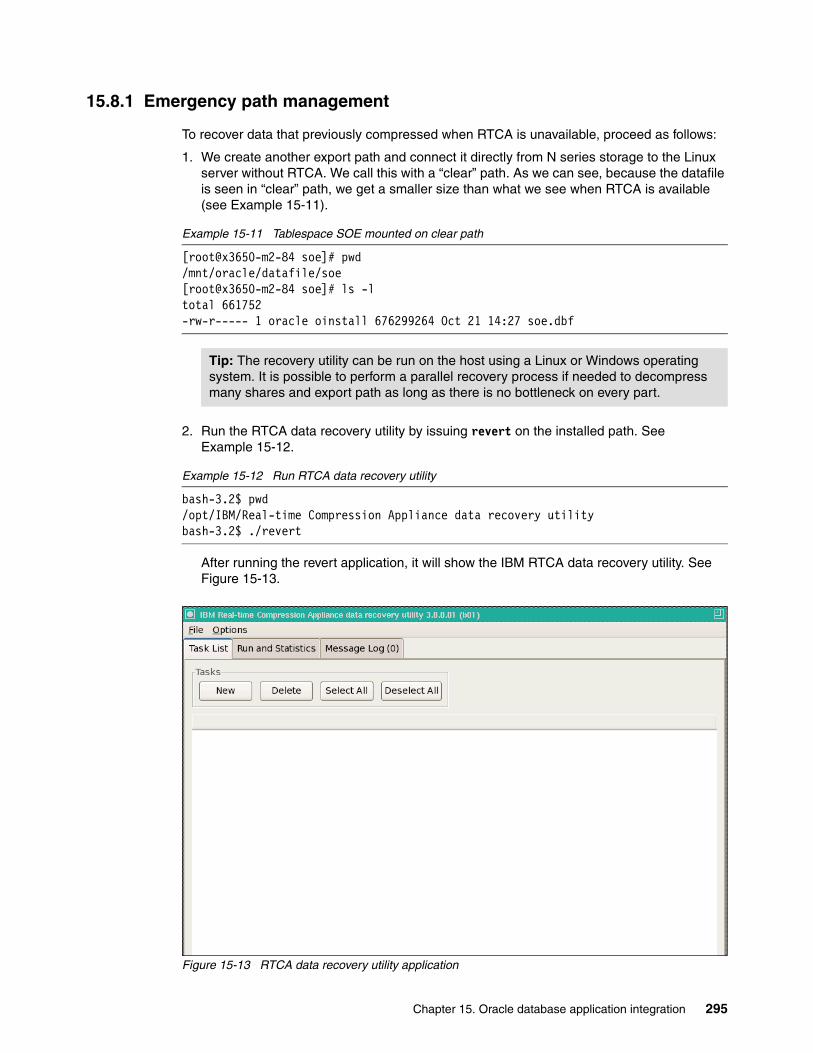
15.8.1 Emergency path management
To recover data that previously compressed when RTCA is unavailable, proceed as follows:
1. We create another export path and connect it directly from N series storage to the Linux server without RTCA. We call this with a “clear” path. As we can see, because the datafile is seen in “clear” path, we get a smaller size than what we see when RTCA is available (see Example 15-11).
Example 15-11 Tablespace SOE mounted on clear path
[root@x3650-m2-84 soe]# pwd/mnt/oracle/datafile/soe[root@x3650-m2-84 soe]# ls -ltotal 661752-rw-r----- 1 oracle oinstall 676299264 Oct 21 14:27 soe.dbf
2. Run the RTCA data recovery utility by issuing revert on the installed path. See Example 15-12.
Example 15-12 Run RTCA data recovery utility
bash-3.2$ pwd/opt/IBM/Real-time Compression Appliance data recovery utilitybash-3.2$ ./revert
After running the revert application, it will show the IBM RTCA data recovery utility. See Figure 15-13.
Figure 15-13 RTCA data recovery utility application
Tip: The recovery utility can be run on the host using a Linux or Windows operating system. It is possible to perform a parallel recovery process if needed to decompress many shares and export path as long as there is no bottleneck on every part.
Chapter 15. Oracle database application integration 295

3. Create a new recovery task to recover the compressed files. We want to recover the datafile to the original location. To make these changes to the Oracle database, select Copy in Place. See Figure 15-14.
Figure 15-14 Set up new task for recovery files
Important: Ensure that you have enough space to save the recovered files.
296 Introduction to IBM Real-time Compression Appliances

4. After clicking OK, we can see on the task list, the status of each task (Figure 15-15).
Figure 15-15 List of Task
5. On the Run and Statistics tab, click the Start button to start decompression process.
We can see in Example 15-13 that the RTCA data recovery utilities use a temporary file on the same directory while processing the decompression datafile. This is the reason that we must have enough space available while recovering the data.
Example 15-13 Temporary file used while decompression in progress
[root@x3650-m2-84 soe]# ls -ltotal 658772-rw-r----- 1 oracle oinstall 673251840 Oct 28 15:51 soe.dbf
[root@x3650-m2-84 soe]# ls -ltotal 2036068-rw-r--r-- 1 oracle oinstall 1407582208 Oct 28 16:54 1403722366.soe.dbf-rw-r----- 1 oracle oinstall 673251840 Oct 28 15:51 soe.dbf
[root@x3650-m2-84 soe]# ls -ltotal 3362252-rw-r----- 1 oracle oinstall 3436191744 Oct 28 15:51 soe.dbf
Attention: Ensure that files that ready to be decompressed are readable. Check from the database server if the datafile is still being locked.
temporary file used when usingcopy in place
initial file in compressed mode
file in uncompressed mode
Chapter 15. Oracle database application integration 297
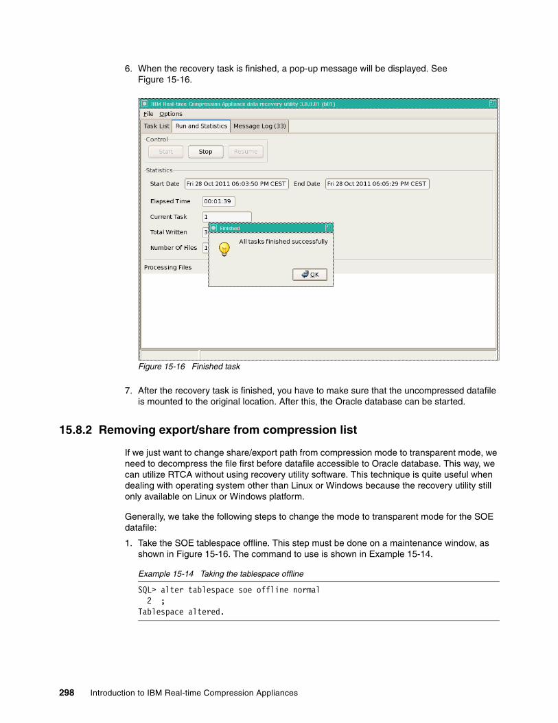
6. When the recovery task is finished, a pop-up message will be displayed. See Figure 15-16.
Figure 15-16 Finished task
7. After the recovery task is finished, you have to make sure that the uncompressed datafile is mounted to the original location. After this, the Oracle database can be started.
15.8.2 Removing export/share from compression list
If we just want to change share/export path from compression mode to transparent mode, we need to decompress the file first before datafile accessible to Oracle database. This way, we can utilize RTCA without using recovery utility software. This technique is quite useful when dealing with operating system other than Linux or Windows because the recovery utility still only available on Linux or Windows platform.
Generally, we take the following steps to change the mode to transparent mode for the SOE datafile:
1. Take the SOE tablespace offline. This step must be done on a maintenance window, as shown in Figure 15-16. The command to use is shown in Example 15-14.
Example 15-14 Taking the tablespace offline
SQL> alter tablespace soe offline normal 2 ;Tablespace altered.
298 Introduction to IBM Real-time Compression Appliances

2. There several options to decompress the files. Using the recovery utility, copy/move files from a compressed mode path to a transparent mode path. In this example, we decompress the file using the move command to a temporary path that is in transparent mode.
3. Check the current location of the compressed datafile (see Example 15-15).
Example 15-15 Current location of Oracle datafiles
SQL> select name from v$datafile;
NAME--------------------------------------------------------------------------------/u01/app/oracle/oradata/orcl/system01.dbf/u01/app/oracle/oradata/orcl/sysaux01.dbf/u01/app/oracle/oradata/orcl/undotbs01.dbf/u01/app/oracle/oradata/orcl/users01.dbf/u01/app/oracle/oradata/orcl/example01.dbf/export/datafile/sh/sh4/sh4.dbf/export/datafile/sh/sh/sh.dbf/export/datafile/sh/sh3/sh3.dbf/export/datafile/soe/soe.dbf/export/datafile/cc/ccdata.dbf/export/datafile/sh/sh5/sh5.dbf
NAME--------------------------------------------------------------------------------/u01/app/oracle/oradata/orcl/users02.dbf
12 rows selected.
SQL>
4. Verify the size of the datafile on the operating system mode (Example 15-16).
Example 15-16 Checking size of datafile
[root@x3650-m2-84 soe]# ls -l /export/datafile/soetotal 3355656-rw-r----- 1 oracle oinstall 3436191744 Oct 28 18:11 soe.dbf
5. Make tablespace offline to preserve consistency and file able to be copied (Example 15-17).
Example 15-17 Make tablespace offline
SQL> alter tablespace soe offline normal;
Tablespace altered.
6. Move files on the Linux host to a transparent mode path. This can be done in many ways, such as creating another export path on the N series using the least directory than on the compressed path. In this case, we use /vol/oracle/datafile/soe as the compressed path. Create another export path on N series /vol/oracle/. This way, when /vol/oracle is mounted on the Linux host, we can also access files on directory to datafile/soe as transparent path (see Example 15-18).
Chapter 15. Oracle database application integration 299
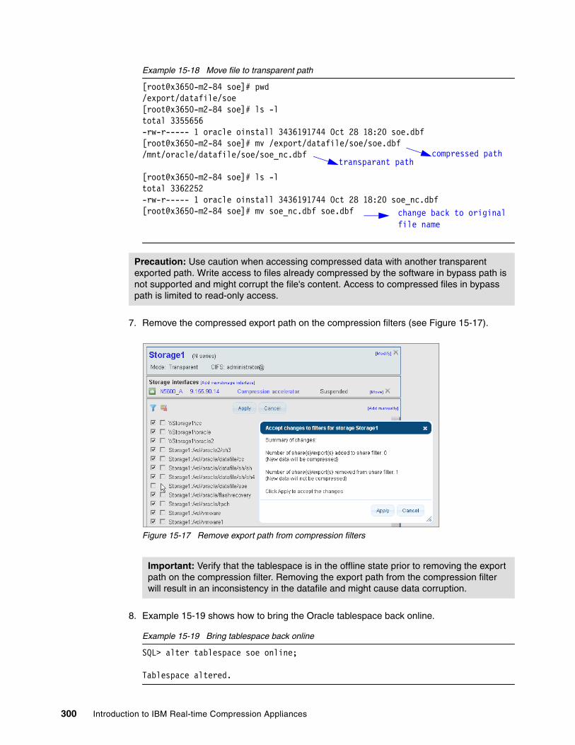
Example 15-18 Move file to transparent path
[root@x3650-m2-84 soe]# pwd/export/datafile/soe[root@x3650-m2-84 soe]# ls -ltotal 3355656-rw-r----- 1 oracle oinstall 3436191744 Oct 28 18:20 soe.dbf[root@x3650-m2-84 soe]# mv /export/datafile/soe/soe.dbf /mnt/oracle/datafile/soe/soe_nc.dbf
[root@x3650-m2-84 soe]# ls -ltotal 3362252-rw-r----- 1 oracle oinstall 3436191744 Oct 28 18:20 soe_nc.dbf[root@x3650-m2-84 soe]# mv soe_nc.dbf soe.dbf
7. Remove the compressed export path on the compression filters (see Figure 15-17).
Figure 15-17 Remove export path from compression filters
8. Example 15-19 shows how to bring the Oracle tablespace back online.
Example 15-19 Bring tablespace back online
SQL> alter tablespace soe online;
Tablespace altered.
Precaution: Use caution when accessing compressed data with another transparent exported path. Write access to files already compressed by the software in bypass path is not supported and might corrupt the file's content. Access to compressed files in bypass path is limited to read-only access.
Important: Verify that the tablespace is in the offline state prior to removing the export path on the compression filter. Removing the export path from the compression filter will result in an inconsistency in the datafile and might cause data corruption.
transparant pathcompressed path
change back to originalfile name
300 Introduction to IBM Real-time Compression Appliances
Chapter 16. File serving solutions
In this chapter, we describe the best practices for deploying the RTCA product into a CIFS or NFS file service environment. Also, in this chapter, we demonstrate a practical approach for using the RTCA product in a file service environment.
For a typical Windows environment, we set up an example CIFS share, with compression by the RTCA product, and deduplication by the underlying NAS controller. We also discuss how to compress automatic CIFS home shares. For a typical UNIX environment, we set up an example export, also with compression by the RTCA product, and deduplication by the underlying NAS controller.
16
Tip: This chapter uses IBM System Storage N series as the NAS system. The different solution and design approaches can be easily applied to other NAS solutions available in the marketplace.
© Copyright IBM Corp. 2013. All rights reserved. 301

16.1 Foundations
It is important that an RTCA implementation builds on the best practices of both the NAS storage controller and NAS client platforms.
Consider the following related best practices in the deployment of the NAS environment prior to the implementation of the RTCA product.
16.1.1 NAS storage controllers
See the best practices guides for your NAS storage controller:
� IBM N series:
– IBM System Storage N series Hardware Guide, SG24-7840
– IBM System Storage N series Software Guide, SG24-7129
– Setting up CIFS and Joining the Active Directory, REDP-4074
– Using the Linux NFS Client with IBM System Storage N series, SG24-7462
– IBM System Storage N series Multiprotocol Use Guide, SG24-7469
– IBM Storage System N series Antivirus Scanning Best Practices Guide, REDP-4084
� NetApp:
– Enterprise File Services Best Practices Index:
http://now.netapp.com/NOW/knowledge/docs/bpg/efs/
– Data ONTAP 7.3 File Access and Protocols Management Guide:
http://now.netapp.com/NOW/knowledge/docs/ontap/rel733/pdfs/ontap/filesag.pdf
� EMC Celerra:
– See the following product documentation:
https://powerlink.emc.com/
16.1.2 NAS clients
See the best practices guides for your NAS client platform:
� Windows (CIFS):
– Windows File Services Best Practices with NetApp Storage Systems:
http://www.netapp.com/us/library/technical-reports/tr-3771.html
� UNIX (NFS):
– AIX:
http://publib.boulder.ibm.com/infocenter/aix/v6r1/index.jsp?topic=%2Fcom.ibm.aix.commadmn%2Fdoc%2Fcommadmndita%2Fnfs_intro.htm
– Linux:
http://nfs.sourceforge.net/nfs-howto/
– Solaris:
http://download.oracle.com/docs/cd/E19455-01/806-0916/6ja8539fd/
302 Introduction to IBM Real-time Compression Appliances

16.2 Common file service requirements
This section includes information about possible file service requirements.
16.2.1 Workload considerations
This section discusses important practical implication when using compression. The behaviors listed below are common for compression algorithms and are not specific to the RTCA product.
Very small filesOverwriting small files (NFS files smaller than 64K or CIFS files smaller than 122 KB) might increase the compressed file size up to 121 KB.
Very large filesWhen a compressed file is opened, its metadata is loaded into memory. In larger files this might take multiple seconds before the appliance will reply to the open operation.
Compressed files greater than 50 GB in size might take multiple seconds to load.
Incompressible file typesWhen compressing files that contain incompressible data, this can be example encrypted data or already compressed data such as mp3 or mpeg files, the compressed file size might exceed the original file's size in some cases.
16.2.2 Compression filters
As previously discussed, to improve the handling of impressible data, you can use compression filters to improve file handling.
File name extension filtersFile name extension filters only pertain to the file name's last two extensions. Multiple extensions separated by a period are not supported. For example, if “gz” is configured as a filter for not compressing, files with tar.gz and gz.tar extensions are filtered too.
Directories to ignoreThis setting does not support directory names containing a space character. It is impossible to exclude directories that include a space in the path name.
WARNING: Never add the NAS root file system (for example, /vol/vol0 or \C$ in the IBM N series product) to the compression accelerator task list. This volume contains the NAS system files, which are read directly by the NAS system.
Reason: The NAS controller will be rendered inoperable if its system files are compressed by the RTCA product.
Attention: Files with an uncompressible first block (32 KB in NFS, 61 KB in CIFS) cannot be compressed by the Compression Accelerator. Such files will be skipped by the Compression Accelerator.
Chapter 16. File serving solutions 303

This setting is also case-sensitive. The list of directories to ignore in Compression Accelerator is case-sensitive, even when running a task to compress a CIFS share. For example, even if the directories to ignore list will include “old”, a directory named “Old” is compressed.
Be patientNewly added compression filters cannot be compressed immediately. After adding a new compression filter, wait 120 seconds before adding this filter in the Compression Accelerator full scan configuration page.
16.3 Planning a CIFS file service
Before implementing RTCA, you need to gain a good understanding of your current IT infrastructure. Because CIFS is mostly linked to Microsoft Windows environments, it is important to understand your Active Directory, NT4 Domain, or Workgroup structure.
The RTCA product is fully compatible with clients that conform to the Common Internet File System (CIFS) access protocol, which is also known as Server Message Block (SMB).
16.3.1 Authentication and authorization
The RTCA product does not participate in the security access negotiation between the CIFS client and the NAS file server. All user access is configured on the underlying NAS storage controller, exactly as if the RTCA product was not in the data path
Although the RTCA product does support connection to an LDAP server, that is for administrative authentication only, and it plays no part in client access to data.
CIFS signingSMB Signing is a feature which is designed to prevent the man-in-the middle attack. Because the compression appliance is an in-line product, the SMB Signing mechanism perceives the appliance as a man-in-the-middle. Thus the SMB Signing feature for the domain controller must be turned off when using the compression appliance.
Listing the available sharesThe RTCA product needs to be able to list the CIFS shares that are being presented by the NAS storage controller.
Access based enumeration (ABE)This option, on the NAS controller, is used to limit the displayed contents of a share to only those files and directories that the user has permission to access. This is different than the default case, where the full content of a share is visible to the user.
For example, if a share contains 100 subdirectories, but the user only has file system permission for five of them, then only those five directories will be visible.
This helps to reduce confusion when multiple users access a common CIFS share.
Attention: Support for the SMB2 protocol was introduced in Version 3.8 of the RTCA product. Prior to that, the SMB2 protocol was unsupported and was failed back to SMB1 by the compression appliance.
304 Introduction to IBM Real-time Compression Appliances

In normal operations, both transparent and compressed mode, the RTCA does not present a user identity of its own. Instead, the user that generated the request is being used, so the file system access, including ABE filtering, will perform as expected.
However, when processing a CIFS share, the Compression Accelerator needs to be given a username and password to compress the existing data. This must be an administrative account so that any ABE filtering does not interfere with the compression process.
Access based share enumeration (ABSE)This option, available on some NAS controllers, is used to limit the display of shares to only those that the user has permission to access. This is different than the default case, where the full list of shares is visible to all users.
For example, if the NAS controller has 100 shares, but the user only has share permission for five of them, then only those five shares will be visible.
This helps to reduce confusion when a user only has access to a subset of the NAS shares.
In normal operations, both transparent and compressed mode, the RTCA uses its predefined CIFS credentials to list the available shares. This must be an administrative account so that any ABSE filtering does not interfere with the share enumeration.
However, the compression accelerator can only process a share if it is enumerated and is visible in the GUI interface.
Note that even if a share is not visible to the RTCA product, the share will still be visible to the clients, and the share contents can still be compressed.
On the IBM N series platform, an example of ABSE is the auto home share feature. In this mode the user’s home share are dynamically created when accessed by the users, removed when idle, and are invisible to other users, including the NAS administrator account. This can present a challenge when using the RTCA to compress their existing data.
16.3.2 Auto home shares
The IBM N series (and NetApp FAS) storage controllers have the ability to dynamically create a user home share when accessed. When the user is not connected to the NAS that home share will not exist, though of course the data still exists un the NAS storage volume. This both simplifies the configuration and reduces the load on the NAS controller.
cifs.home_dir_namestylecifs.home_dirs_public_for_admin on
The following steps will help you to perform the task:
1. Define the parent location of the user’s home directories.
2. Specify the naming style of the home directories.
3. Create the user’s individual home directories.
4. The home shares will now be dynamically created when accessed.
Tip: The CIFS shares command does not display the list of auto home shares.
Chapter 16. File serving solutions 305
16.4 Planning an NFS file service
Most UNIX clients use NFS for remote file access. Sun Microsystems introduced NFS in 1985. Since then, it has become a de facto standard protocol, used by 10 million systems worldwide. NFS is particularly common on UNIX-based systems, but NFS implementations are available for virtually every modern computing platform in current use, from desktops to supercomputers. Only when used by UNIX-based systems, however, does NFS closely resemble the behavior of a client’s local file system. NFSv4 addresses some weaknesses in earlier NFS versions such as ACL, security, and file system namespace, and so on. However, this is beyond the scope of this book.
The compression appliance is fully compatible with clients that conform to the NFSv3 protocol standards. NFSv3 is supported over TCP and UDP.
16.5 Block-mode pass-through
Although the RTCA product is designed to provide compression to a NAS environment (NFS and CIFS), it is possible that the underlying NAS controller will also present storage by one of the block-mode protocols.
16.5.1 FCP protocol access
Because the FC protocol is transported over a completely separate physical media (fibre optic cable) there is no interaction with the RTCA product.
Because the RTCA product compresses the NAS data, reducing the related workload on the NAS controller, there is the potential that this will make more NAS resources available to process the FC traffic. This might have the indirect effect of improving FC performance, but will depend on the specifics of your storage environment.
16.5.2 iSCSI protocol access
Although the iSCSI protocol is transported over the same physical media (Ethernet cable) there is no interaction with the RTCA product.
Because the RTCA product compresses the NAS data, reducing the related workload on the NAS controller, there is the potential that this will make more NAS resources available to process the iSCSI traffic. This might have the indirect effect of improving FC performance, but will depend on the specifics of your storage environment.
Under normal conditions it is not necessary to bypass the RTCA product for any Ethernet traffic.
Support: The NFSv2 and NFSv4 protocols are unsupported and pass through the compression appliance transparently. They can be used to access data on the underlying NAS storage controller, but they are unable to correctly read any data that has been compressed by the RTCA product.
306 Introduction to IBM Real-time Compression Appliances

16.6 Setting up a CIFS file service
This section describes several scenarios for using the RTCA product to compress an existing CIFS file service.
The CIFS function of an IBM N series storage controller was used for all NAS examples.
16.6.1 Configuring the NAS storage controller
Prior to applying the RTCA product to the CIFS file service, it is necessary to configure some settings, and to create the volumes and CIFS shares.
Selecting the CIFS protocol versionAlthough the RTCA product introduced partial support for SMB 2.0 in version 3.8, it is still necessary to disable SMBv2 on the NAS storage controller.
Enter the command shown in Example 16-1 to set the CIFS protocol mode on the NAS controller.
Example 16-1 Disabling SMB 2.0 protocol
NAS> option cifs.smb2.enable off
Any client sessions that use SMB 2.0 to connect by the RTCA product will be stepped down to SMBv1 for the back-end communication to the NAS controller.
Tips:
� To avoid direct access to compressed data by clients without passing the RTCA product, it is best to connect all network interfaces of the NAS storage server with the RTCA product.
� If you have free Ethernet ports on your NAS storage server and want to use these ports for iSCSI or replication purposes, at these Ethernet ports all NAS protocols must be deactivated.
Assumptions:
� This section assumes that the initial configuration of the RTCA product and the NAS storage controller have both been completed.
� We assume that the RTCA management port (IP addresses), network (bonds and bridges), and storage (NAS controllers) have already been configured. We also assume that the NAS controller’s CIFS protocol has already been configured.
� At this stage, all CIFS (and NFS) traffic is already passing through the RTCA product in transparent mode. However, no data is being compressed or uncompressed.
� Use the initial setup procedure.
Support: Future versions of the RTCA product might include full support for the SMB2 protocol. See the release notes for those versions for advice on how to configure the NAS controller if that is the case.
Chapter 16. File serving solutions 307

Disabling SMB signingThe SMB Signing feature is designed to prevent the man-in-the middle attack. Because the compression appliance is an in-line product, the SMB Signing mechanism perceives the appliance as a man-in-the-middle, intercepting traffic between the client and the NAS controller. Therefore, the SMB Signing feature needs to be disabled on the NAS controller when using the RTCA product.
Enter the command shown in Example 16-2 to disable SMB signing on the NAS controller.
Example 16-2 Disable SMB signing
NAS> option cifs.signing.enable off
All other CIFS settings on the NAS controller, such as visibility of the ~snapshot directory, were left as default.
Example CIFS shareFor our lab, we created the following CIFS shares on the NAS storage controller.
Although our lab examples rely on the CIFS function of the NAS controller, the focus of this book is not the NAS configuration per se. We have assumed that the reader is already a competent NAS administrator, so that material is not described here.
For more information about NAS features and administration, see the IBM System Storage N series Software Guide, SG24-7129. Our sample CIFS share is shown in Example 16-3.
Example 16-3 Sample CIFS share
NAS> cifs shares cifs_vol1
Name Mount Point Description---- ----------- -----------cifs_vol1 /vol/cifs_vol1
everyone / No AccessN5600-B\cifsuser1 / Full Control
For the purposes of our lab examples, we populated the sample CIFS share with a variety of file types, including the Canterbury corpus, which was obtained from the following website:
http://corpus.canterbury.ac.nz/
Existing dataAt the start of our lab, the CIFS share contained some data, as shown in Example 16-4.
Example 16-4 Sample CIFS share at start of the lab
NAS> df -Sh /vol/cifs_vol1Filesystem used compressed a-sis %saved/vol/cifs_vol1/ 28MB 0KB 608KB 2%
You will notice that the sample share contained a small amount of NAS deduplicated data (shown in the “a-sis” column in Example 16-4). This was done to demonstrate the effect that the RTCA product has on existing NAS deduplicated data.
Existing snapshot copiesThere were also a number of existing snapshot copies, as shown in Example 16-5.
308 Introduction to IBM Real-time Compression Appliances

Example 16-5 Existing snapshot copies at start of the lab
NAS> snap list
Volume cifs_vol1working...
%/used %/total date name---------- ---------- ------------ -------- 3% ( 3%) 0% ( 0%) Oct 18 12:00 hourly.0 6% ( 3%) 0% ( 0%) Oct 18 08:00 hourly.1 7% ( 1%) 0% ( 0%) Oct 18 00:00 nightly.0 8% ( 1%) 0% ( 0%) Oct 17 20:00 hourly.2 10% ( 1%) 0% ( 0%) Oct 17 16:00 hourly.3 11% ( 2%) 0% ( 0%) Oct 17 12:00 hourly.4 12% ( 2%) 0% ( 0%) Oct 17 08:00 hourly.5 13% ( 1%) 0% ( 0%) Oct 17 00:00 nightly.1
There had been little change to the sample volume, so the percentage changed was also very low.
Dummy workloadTo test the effect of enabling RTCA compression with a running CIFS workload, we configured a Windows PC to continuously run an IOmeter benchmark on the sample share.
The IOmeter product was downloaded from the following website:
http://www.iometer.org
Note that this was not intended as a performance benchmark, and was chosen as a simple way to provide a continuous CIFS workload during our implementation.
16.6.2 Configuring the RTCA product
This section assumes that the initial configuration of the RTCA product has been completed.
We assume that the RTCA management port (IP addresses), network (bonds and bridges), and storage (NAS controllers) have already been configured.
Authentication and authorizationYou need to configure the RTCA with a valid NAS domain user name and password to allow it to list the available CIFS shares. This list of CIFS shares will later be used to configure the compression filters and Compression Accelerator function.
Follow these steps to configure the CIFS credentials on the RTCA product:
1. Log in to the RTCA web interface.
2. In the left-hand menu, under Configuration, select Storage.
3. In the Storage systems view, select your NAS controller:
a. If your NAS controller does not appear in the list, select [Add new storage].
4. In the upper right corner, select [Modify] to configure the CIFS credentials.
Chapter 16. File serving solutions 309
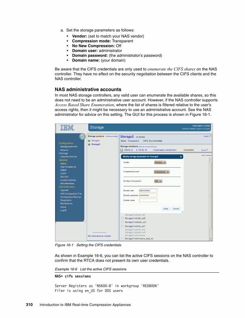
a. Set the storage parameters as follows:
• Vendor: (set to match your NAS vendor)• Compression mode: Transparent• No New Compression: Off• Domain user: administrator• Domain password: (the administrator’s password)• Domain name: (your domain)
Be aware that the CIFS credentials are only used to enumerate the CIFS shares on the NAS controller. They have no effect on the security negotiation between the CIFS clients and the NAS controller.
NAS administrative accountsIn most NAS storage controllers, any valid user can enumerate the available shares, so this does not need to be an administrative user account. However, if the NAS controller supports Access Based Share Enumeration, where the list of shares is filtered relative to the user’s access rights, then it might be necessary to use an administrative account. See the NAS administrator for advice on this setting. The GUI for this process is shown in Figure 16-1.
Figure 16-1 Setting the CIFS credentials
As shown in Example 16-6, you can list the active CIFS sessions on the NAS controller to confirm that the RTCA does not present its own user credentials.
Example 16-6 List the active CIFS sessions
NAS> cifs sessions
Server Registers as 'N5600-B' in workgroup 'REDBOOK'Filer is using en_US for DOS users
310 Introduction to IBM Real-time Compression Appliances

Using Local Users authentication====================================================PC IP(PC Name) (user)#shares #files
NAS>
We have assumed that the Storage interfaces (IP address, and so on) for the NAS controller have already been defined.
16.6.3 Storage compression mode
When a storage system is defined to the RTCA it is assigned a compression mode. This controls whether the system leaves the new data unchanged (transparent mode) or compresses all new data by default (compressed mode). In our lab we initially set the storage controllers to transparent mode.
Transparent modeIn this mode, no new user access is compressed, and uncompressed, by default. Note however, that all CIFS (and NFS) traffic is already passing through the RTCA product in transparent mode. Follow these steps to view the list of available CIFS (and NFS) shares on the NAS controller:
1. Log in to the RTCA web interface.
2. In the left-hand menu, under Configuration, select Storage.
3. In the Storage systems view, select your NAS controller:
This will update the display to show the available CIFS shares.
The GUI for this process is shown in Figure 16-2.
Figure 16-2 Viewing the available CIFS shares in transparent mode
For the example CIFS share in Figure 16-2, in storage transparent mode, the two check boxes have the following effect:
� Left box - Compression filter:
– Unchecked = No compression or decompression
– Checked = New data is compressed, existing data is uncompressed
� Right box - No new compression (only visible when left box is checked):
– Unchecked = New data IS compressed, existing data is uncompressed
– Checked = New data is NOT compressed, existing data is uncompressed
Chapter 16. File serving solutions 311
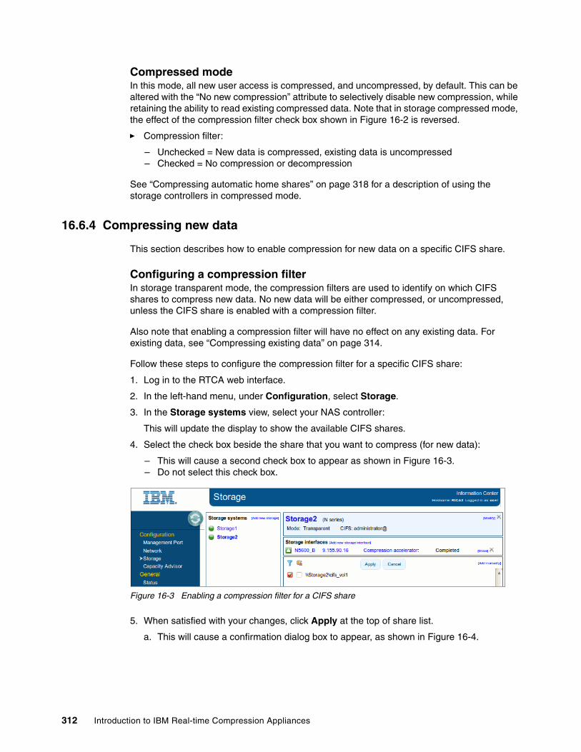
Compressed modeIn this mode, all new user access is compressed, and uncompressed, by default. This can be altered with the “No new compression” attribute to selectively disable new compression, while retaining the ability to read existing compressed data. Note that in storage compressed mode, the effect of the compression filter check box shown in Figure 16-2 is reversed.
� Compression filter:
– Unchecked = New data is compressed, existing data is uncompressed– Checked = No compression or decompression
See “Compressing automatic home shares” on page 318 for a description of using the storage controllers in compressed mode.
16.6.4 Compressing new data
This section describes how to enable compression for new data on a specific CIFS share.
Configuring a compression filterIn storage transparent mode, the compression filters are used to identify on which CIFS shares to compress new data. No new data will be either compressed, or uncompressed, unless the CIFS share is enabled with a compression filter.
Also note that enabling a compression filter will have no effect on any existing data. For existing data, see “Compressing existing data” on page 314.
Follow these steps to configure the compression filter for a specific CIFS share:
1. Log in to the RTCA web interface.
2. In the left-hand menu, under Configuration, select Storage.
3. In the Storage systems view, select your NAS controller:
This will update the display to show the available CIFS shares.
4. Select the check box beside the share that you want to compress (for new data):
– This will cause a second check box to appear as shown in Figure 16-3.– Do not select this check box.
Figure 16-3 Enabling a compression filter for a CIFS share
5. When satisfied with your changes, click Apply at the top of share list.
a. This will cause a confirmation dialog box to appear, as shown in Figure 16-4.
312 Introduction to IBM Real-time Compression Appliances

Figure 16-4 Confirm the new compression filter
6. The panel will then update to show the new compression filter.
At this point, any new (or updated) data written to this CIFS share will be compressed by the RTCA product.
Configuring file extensions to excludeThis section describes how to filter the compression engine to exclude specific file types. Because some data types are either already compressed (for example, ZIP files) or naturally uncompressible, they must be excluded from the RTCA compression process.
Follow these steps to configure the file type exclusions:
1. Log in to the RTCA web interface.
2. In the left-hand menu, under Configuration, select Storage.
3. In the Storage systems view, select your NAS controller.
4. In the lower left corner, select File extensions to exclude.
This will open a new dialog box, as shown in Figure 16-5.
Figure 16-5 Configuring file extensions to exclude
5. Update the exclusion list as required. Then click Apply to save your changes.
From this point, any new data that matches these file extensions will not compressed by the RTCA product.
Chapter 16. File serving solutions 313
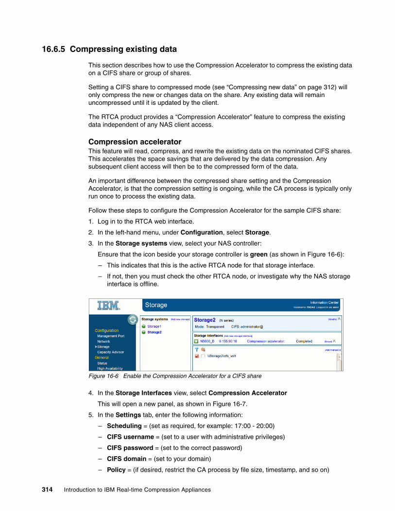
16.6.5 Compressing existing data
This section describes how to use the Compression Accelerator to compress the existing data on a CIFS share or group of shares.
Setting a CIFS share to compressed mode (see “Compressing new data” on page 312) will only compress the new or changes data on the share. Any existing data will remain uncompressed until it is updated by the client.
The RTCA product provides a “Compression Accelerator” feature to compress the existing data independent of any NAS client access.
Compression acceleratorThis feature will read, compress, and rewrite the existing data on the nominated CIFS shares. This accelerates the space savings that are delivered by the data compression. Any subsequent client access will then be to the compressed form of the data.
An important difference between the compressed share setting and the Compression Accelerator, is that the compression setting is ongoing, while the CA process is typically only run once to process the existing data.
Follow these steps to configure the Compression Accelerator for the sample CIFS share:
1. Log in to the RTCA web interface.
2. In the left-hand menu, under Configuration, select Storage.
3. In the Storage systems view, select your NAS controller:
Ensure that the icon beside your storage controller is green (as shown in Figure 16-6):
– This indicates that this is the active RTCA node for that storage interface.
– If not, then you must check the other RTCA node, or investigate why the NAS storage interface is offline.
Figure 16-6 Enable the Compression Accelerator for a CIFS share
4. In the Storage Interfaces view, select Compression Accelerator
This will open a new panel, as shown in Figure 16-7.
5. In the Settings tab, enter the following information:
– Scheduling = (set as required, for example: 17:00 - 20:00)
– CIFS username = (set to a user with administrative privileges)
– CIFS password = (set to the correct password)
– CIFS domain = (set to your domain)
– Policy = (if desired, restrict the CA process by file size, timestamp, and so on)
314 Introduction to IBM Real-time Compression Appliances

– Directories to ignore = (typically used to prevent the CA from processing snapshot copies)
– Maximum total throughput (MB/sec) = (if desired, throttle the CA process to a specified throughput)
– Amount of changes = (if desired, stop the CA process after the specified amount of change within the time frame)
– Free space threshold = (if desired, stop the CA process if the free space on the share reaches this limit)
– Interval between files (ms) = (if desired, throttle the CA process by imposing a delay between file processing)
Figure 16-7 Configure the Compression Accelerator
6. In the Shares tab (shown in Figure 16-8), select the CIFS share to compress.
Figure 16-8 Select a CIFS share for the Compression Accelerator
7. Skip the Exports tab
8. In the Status tab (shown in Figure 16-9), review the current status.
Click Start to initiate the CA process.
This will update the display to show the files being compressed.
Chapter 16. File serving solutions 315
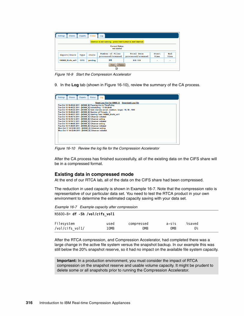
Figure 16-9 Start the Compression Accelerator
9. In the Log tab (shown in Figure 16-10), review the summary of the CA process.
Figure 16-10 Review the log file for the Compression Accelerator
After the CA process has finished successfully, all of the existing data on the CIFS share will be in a compressed format.
Existing data in compressed modeAt the end of our RTCA lab, all of the data on the CIFS share had been compressed.
The reduction in used capacity is shown in Example 16-7. Note that the compression ratio is representative of our particular data set. You need to test the RTCA product in your own environment to determine the estimated capacity saving with your data set.
Example 16-7 Example capacity after compression
N5600-B> df -Sh /vol/cifs_vol1
Filesystem used compressed a-sis %saved/vol/cifs_vol1/ 10MB 0MB 0MB 0%
After the RTCA compression, and Compression Accelerator, had completed there was a large change in the active file system versus the snapshot backup. In our example this was still below the 20% snapshot reserve, so it had no impact on the available file system capacity.
Important: In a production environment, you must consider the impact of RTCA compression on the snapshot reserve and usable volume capacity. It might be prudent to delete some or all snapshots prior to running the Compression Accelerator.
316 Introduction to IBM Real-time Compression Appliances
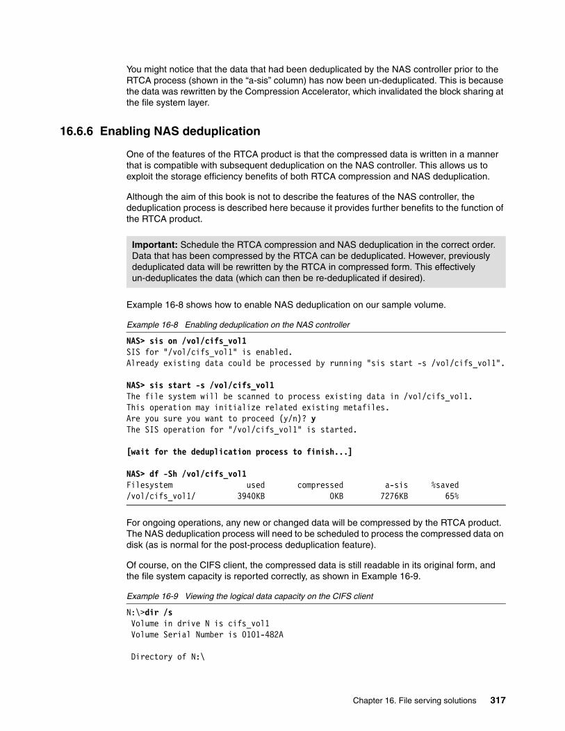
You might notice that the data that had been deduplicated by the NAS controller prior to the RTCA process (shown in the “a-sis” column) has now been un-deduplicated. This is because the data was rewritten by the Compression Accelerator, which invalidated the block sharing at the file system layer.
16.6.6 Enabling NAS deduplication
One of the features of the RTCA product is that the compressed data is written in a manner that is compatible with subsequent deduplication on the NAS controller. This allows us to exploit the storage efficiency benefits of both RTCA compression and NAS deduplication.
Although the aim of this book is not to describe the features of the NAS controller, the deduplication process is described here because it provides further benefits to the function of the RTCA product.
Example 16-8 shows how to enable NAS deduplication on our sample volume.
Example 16-8 Enabling deduplication on the NAS controller
NAS> sis on /vol/cifs_vol1SIS for "/vol/cifs_vol1" is enabled.Already existing data could be processed by running "sis start -s /vol/cifs_vol1".
NAS> sis start -s /vol/cifs_vol1The file system will be scanned to process existing data in /vol/cifs_vol1.This operation may initialize related existing metafiles.Are you sure you want to proceed (y/n)? yThe SIS operation for "/vol/cifs_vol1" is started.
[wait for the deduplication process to finish...]
NAS> df -Sh /vol/cifs_vol1Filesystem used compressed a-sis %saved/vol/cifs_vol1/ 3940KB 0KB 7276KB 65%
For ongoing operations, any new or changed data will be compressed by the RTCA product. The NAS deduplication process will need to be scheduled to process the compressed data on disk (as is normal for the post-process deduplication feature).
Of course, on the CIFS client, the compressed data is still readable in its original form, and the file system capacity is reported correctly, as shown in Example 16-9.
Example 16-9 Viewing the logical data capacity on the CIFS client
N:\>dir /s Volume in drive N is cifs_vol1 Volume Serial Number is 0101-482A
Directory of N:\
Important: Schedule the RTCA compression and NAS deduplication in the correct order. Data that has been compressed by the RTCA can be deduplicated. However, previously deduplicated data will be rewritten by the RTCA in compressed form. This effectively un-deduplicates the data (which can then be re-deduplicated if desired).
Chapter 16. File serving solutions 317

[directoy listing not shown]
Total Files Listed: 125 File(s) 29,526,465 bytes 36 Dir(s) 8,585,900,032 bytes free
However, the true used capacity can been seen on the client by opening Explorer, then right-clicking the CIFS drive letter, and selecting Properties, as shown in Figure 16-11.
Figure 16-11 Viewing the physical data capacity on the CIFS client
The slight variation in reported capacity is due to the different ways that the NAS controller and Windows report disk usage.
16.6.7 Compressing automatic home shares
This section describes how to correctly configure the RTCA to work with auto home shares.
The IBM N series storage controller has the ability to dynamically create a CIFS share on demand when a user access their home directory. When the user disconnects, the share is automatically removed.
This reduces the load on the NAS controller, because it now only needs to maintain those CIFS home shares that are actively in use at any particular time. It also reduces the administrative burden of needing to define individual user home shares, which might be many thousands of users in a large environment. Another interesting feature of automatic home shares is that they are only visible to the individual account owner, even the NAS administrator cannot list this type of share.
Be aware that if the auto home shares cannot be listed by an administrative user, then they cannot be shown in the compression filter GUI. Nor can they be processed by the Compression Accelerator, as this is a form of access based share enumeration.
318 Introduction to IBM Real-time Compression Appliances

Configuring the NAS controllerThis section describes how to configure the auto home share feature on the IBM N series storage controller.
Step 1: Create a parent directory for the home sharesFollow these steps to configure the parent directory and CIFS share:
1. Log in to the NAS administrative interface (CLI examples shown here).
2. Create a new volume to contain the user home shares, as shown in Example 16-10.
a. Set the size and other parameters to suit your requirements.
b. The CIFS home shares will be created as sub-directories under this volume.
Example 16-10 Create a NAS volume to contain the home shares
NAS> vol create cifs_home -s none aggr0 10gCreation of volume 'cifs_home' with size 10g on containing aggregate'aggr0' has completed.
3. Configure the NAS file system security mode for CIFS access, as shown in Example 16-11.
This might already be correct, depending on the NAS default security style.
Example 16-11 Configure the NAS security style for the volume
NAS> qtree status cifs_homeVolume Tree Style Oplocks Status -------- -------- ----- -------- ---------cifs_home unix enabled normal
NAS> qtree security /vol/cifs_home ntfsThu Oct 13 15:09:53 GMT [N5600-B: wafl.quota.sec.change:notice]: security style for /vol/cifs_home/ changed from unix to ntfs
4. Create a CIFS share for the containing volume, as shown in Example 16-12
a. Remove access permissions for “everyone.”
b. Create access permissions for “administrator.”
Example 16-12 Create a CIFS share and set the access permissions
NAS> cifs shares -add cifs_home /vol/cifs_homeThe share name 'cifs_home' will not be accessible by some MS-DOS workstations
NAS> cifs shares cifs_homeName Mount Point Description---- ----------- -----------cifs_home /vol/cifs_home
everyone / Full Control
Configuration:
� This book does not normally seek to describe how to configure the NAS controller, and is mainly concerned with integration with the RTCA product.
� The process to configure the auto home shares on the IBM N series controller is described here because it needs to be understood for a successful RTCA deployment.
Chapter 16. File serving solutions 319

NAS> cifs access -delete cifs_home everyone 1 share(s) have been successfully modified
NAS> cifs access cifs_home administrator "Full Control"1 share(s) have been successfully modified
NAS> cifs shares cifs_homeName Mount Point Description---- ----------- -----------cifs_home /vol/cifs_home
N5600-B\administrator / Full Control
The CIFS share is now ready for administrative access.
Step 2: Set the parent directory locationFollow these steps to configure the parent directory location:
1. Check whether a CIFS home directory has already been configured, as shown in Example 16-13.
If this parameter is already configured you must investigate before continuing.
Example 16-13 Check the CIFS home directory location
NAS> cifs homedirNo CIFS home directory paths.
NAS> rdfile /etc/cifs_homedir.cfg## This file contains the path(s) used by the filer to determine if a# CIFS user has a home directory. See the System Administrator's Guide# for a full description of this file and a full description of the# CIFS homedir feature.## There is a limit to the number of paths that may be specified.# Currently that limit is 1000.# Paths must be entered one per line.## After editing this file, use the console command "cifs homedir load"# to make the filer process the entries in this file.## Note that the "#" character is valid in a CIFS directory name.# Therefore the "#" character is only treated as a comment in this# file if it is in the first column.## Two example path entries are given below.# /vol/vol0/users1# /vol/vol1/users2#
Tip: This CIFS share will not be accessed directly by the users. Instead it will be used by the RTCA product to access the contents of the auto home shares that are in sub-directories of the containing volume.
320 Introduction to IBM Real-time Compression Appliances

2. Configure the CIFS home directory parameter, as shown in Example 16-14.
Be careful with the wrfile command, because it is easy to make a mistake and overwrite the configuration file with blank data.
Example 16-14 Set the CIFS home directory location
NAS> wrfile -a /etc/cifs_homedir.cfg /vol/cifs_home
NAs> cifs homedir load
NAS> cifs homedir/vol/cifs_home
The CIFS service now knows where to look for the users home directories when automatically creating the user’s home shares.
Step 3: Set the auto home directory name styleFollow these steps to configure the naming standard for the auto home shares:
1. Configure the naming style for the auto home share, as shown in Example 16-15.
In our lab we chose the default naming style. You will need to set this to match the requirements of your environment.
Example 16-15 Set the CIFS home directory name style
NAS> options cifs.home_dir_namestyle ntname
See the NAS product manual for a description of the other directory naming styles.
Step 4: Create the user’s home directoriesFollow these steps to create the user’s home directory on the NAS controller:
1. Log in to the NAS client (for example, a Windows PC).
2. Create the home directory on the NAS controller, as shown in Example 16-16:
a. Detach any existing CIFS connections.
b. Authenticate to the NAS controller as the “administrator” user account.
c. Create the CIFS user’s home directory (under the “homedir” location that we configured in “Step 2: Set the parent directory location” on page 320).
Chapter 16. File serving solutions 321

Example 16-16 Make a home directory for the CIFS user/s
C:\>net use * /dYou have these remote connections:
\\nas2\IPC$Continuing will cancel the connections.
Do you want to continue this operation? (Y/N) [N]: yThe command completed successfully.
C:\>net use \\nas2 /user:administratorThe password or user name is invalid for \\nas2.
Enter the password for 'administrator' to connect to 'nas2':********The command completed successfully.
C:\>mkdir \\nas2\cifs_home\cifsuser1
At this point, the CIFS auto home share is ready to access from the NAS client.
Step 5: Access the auto home shareFollow these steps to connect the user to their new home directory on the NAS controller:
1. Log in to the NAS client (for example, a Windows PC).
2. Connect to the new auto home share, as shown in Example 16-17:
a. Detach any existing CIFS connections.
b. Make a connection to the new CIFS share.
c. Authenticate to the NAS controller as the “cifsuser1” user account. (Of course, you must change this to suit your user account name.)
Example 16-17 Connect to the new CIFS auto home share
C:\>net use * /dYou have these remote connections:
\\nas2\IPC$Continuing will cancel the connections.
Do you want to continue this operation? (Y/N) [N]: yThe command completed successfully.
C:\>net use h: \\nas2\cifsuser1 /user:cifsuser1The password or user name is invalid for \\nas2\cifsuser1.
Enter the password for 'cifsuser1' to connect to 'nas2':The command completed successfully.
Assuming that you have configured the share permissions and security style correctly, the user will now be able to read and write to their new CIFS home share.
When the user disconnects their CIFS session, the share will automatically be removed. Of course, the underlying directory and its contents remain on the NAS controller. They will be ready to be accessed on demand the next time the user connects to the system.
322 Introduction to IBM Real-time Compression Appliances
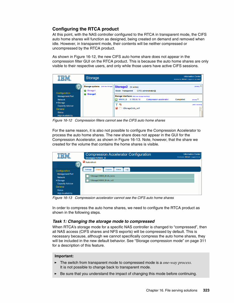
Configuring the RTCA productAt this point, with the NAS controller configured to the RTCA in transparent mode, the CIFS auto home shares will function as designed, being created on demand and removed when idle. However, in transparent mode, their contents will be neither compressed or uncompressed by the RTCA product.
As shown in Figure 16-12, the new CIFS auto home share does not appear in the compression filter GUI on the RTCA product. This is because the auto home shares are only visible to their respective users, and only while those users have active CIFS sessions.
Figure 16-12 Compression filters cannot see the CIFS auto home shares
For the same reason, it is also not possible to configure the Compression Accelerator to process the auto home shares. The new share does not appear in the GUI for the Compression Accelerator, as shown in Figure 16-13. Note, however, that the share we created for the volume that contains the home shares is visible.
Figure 16-13 Compression accelerator cannot see the CIFS auto home shares
In order to compress the auto home shares, we need to configure the RTCA product as shown in the following steps.
Task 1: Changing the storage mode to compressedWhen RTCA’s storage mode for a specific NAS controller is changed to “compressed”, then all NAS access (CIFS shares and NFS exports) will be compressed by default. This is necessary because, although we cannot specifically compress the auto home shares, they will be included in the new default behavior. See “Storage compression mode” on page 311 for a description of this feature.
Important:
� The switch from transparent mode to compressed mode is a one-way process. It is not possible to change back to transparent mode.
� Be sure that you understand the impact of changing this mode before continuing.
Chapter 16. File serving solutions 323
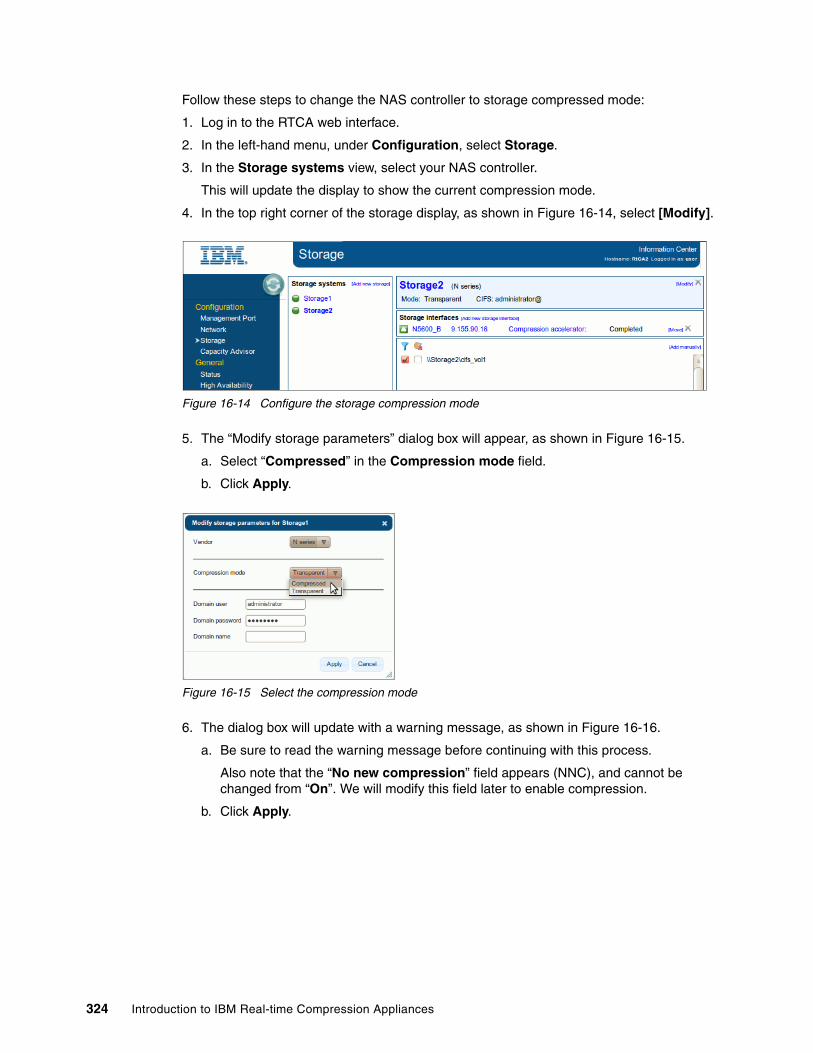
Follow these steps to change the NAS controller to storage compressed mode:
1. Log in to the RTCA web interface.
2. In the left-hand menu, under Configuration, select Storage.
3. In the Storage systems view, select your NAS controller.
This will update the display to show the current compression mode.
4. In the top right corner of the storage display, as shown in Figure 16-14, select [Modify].
Figure 16-14 Configure the storage compression mode
5. The “Modify storage parameters” dialog box will appear, as shown in Figure 16-15.
a. Select “Compressed” in the Compression mode field.
b. Click Apply.
Figure 16-15 Select the compression mode
6. The dialog box will update with a warning message, as shown in Figure 16-16.
a. Be sure to read the warning message before continuing with this process.
Also note that the “No new compression” field appears (NNC), and cannot be changed from “On”. We will modify this field later to enable compression.
b. Click Apply.
324 Introduction to IBM Real-time Compression Appliances

Figure 16-16 The compressed mode warning message
7. The display will then return to the main storage view, as shown in Figure 16-17.
Note that the list of CIFS shares (and NFS exports) has now changed. Because all access now defaults to compressed mode, the meaning of the check boxes is reversed to now indicate which shares NOT to compress.
All access to the NAS controller will now default to compressed mode. However, although any existing data will be uncompressed as required, no new data will be compressed until the No new compression (NNC) setting is changed.
To change the NNC setting, select [Modify] in the top right corner of the storage display, as shown in Figure 16-17.
Figure 16-17 The storage compressed mode interface (compression disabled)
Chapter 16. File serving solutions 325
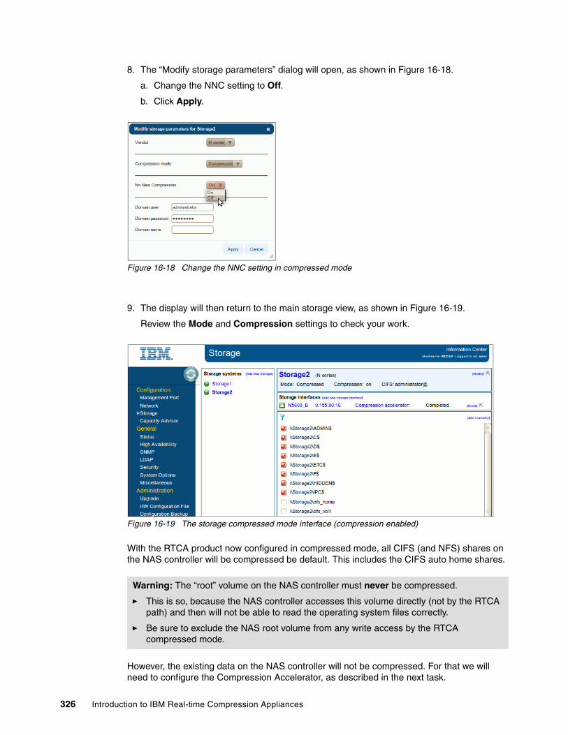
8. The “Modify storage parameters” dialog will open, as shown in Figure 16-18.
a. Change the NNC setting to Off.
b. Click Apply.
Figure 16-18 Change the NNC setting in compressed mode
9. The display will then return to the main storage view, as shown in Figure 16-19.
Review the Mode and Compression settings to check your work.
Figure 16-19 The storage compressed mode interface (compression enabled)
With the RTCA product now configured in compressed mode, all CIFS (and NFS) shares on the NAS controller will be compressed be default. This includes the CIFS auto home shares.
However, the existing data on the NAS controller will not be compressed. For that we will need to configure the Compression Accelerator, as described in the next task.
Warning: The “root” volume on the NAS controller must never be compressed.
� This is so, because the NAS controller accesses this volume directly (not by the RTCA path) and then will not be able to read the operating system files correctly.
� Be sure to exclude the NAS root volume from any write access by the RTCA compressed mode.
326 Introduction to IBM Real-time Compression Appliances

Task 2: Configuring the Compression AcceleratorBecause the CIFS auto home share itself is not visible in the Compression Accelerator GUI (see Figure 16-13 on page 323), we need to configure the CA to process a point lower in the NAS file system.
Configuring the Compression Accelerator here is identical to the process described in “Compressing existing data” on page 314.
1. Repeat the steps as described earlier, but in the Shares, tab select the volume share (that contains the auto home shares)
In our lab example, this is the “cifs_home” share, as shown in Figure 16-20.
Figure 16-20 Select the CIFS share to process with the Compression Accelerator
The Compression Accelerator will then process the existing data in the volume that contains the CIFS auto home shares. Because the NAS controller is now set to compressed mode, the RTCA will compress any new writes from the client, and also uncompress data when accessed from the client.
16.6.8 Accessing the compressed data
This section describes the CIFS client’s view of the NAS data after it has been compressed by the RTCA product.
Accessing data through the compressed pathWhen the RTCA is configured correctly, the CIFS client can access the compressed data exactly as expected. The file contents, and all file meta-data, are apparently unchanged.
Chapter 16. File serving solutions 327

Figure 16-21 shows a file that was accessed from a compressed (and deduplicated) CIFS share.
Figure 16-21 Correct access to the compressed data
Accessing data through the transparent pathIf the RTCA is configured incorrectly, the CIFS client will not be able to access the compressed data. The file contents will appear corrupt to the CIFS client.
For the purpose of demonstration only, the volume containing the sample CIFS share was duplicated on the NAS controller by the NAS volcopy command. This volume contained the RTCA compressed data, but was configured for transparent access, bypassing the RTCA product’s decompression algorithms.
The result of incorrectly accessing the compressed data can be seen in Figure 16-22.
Figure 16-22 Incorrect access to the compressed data
You will notice that Figure 16-22 shows the same file as in Figure 16-21, but it is now unusable. The first three characters of the file, “CMP” identify this as an RTCA compressed file.
Tip: Any compressed data will still be accessed correctly if the NNC setting is enabled on an existing compressed share. The only effect is that new data will not be compressed.
328 Introduction to IBM Real-time Compression Appliances

During normal operations, access to the compressed data must always be through the RTCA compressed path. However, this is the way the files will appear if the RTCA is unavailable (for example, at a DR site with no local RTCA product).
If the RTCA is unavailable, the file can be manually uncompressed with the RTCA data recovery tool.
16.6.9 Calculating the compression ratio
Although it is not the intent of this book to provide guidance regarding RTCA performance or compression ratios, Table 16-1 shows sample compression ratios from our lab environment.
Table 16-1 Example compression ratios (with compression and deduplication)
Obviously, the RTCA performance and compression ratios will vary depending on the NAS hardware platform and specific data set used. We encourage you to test the product in your environment before any production implementation.
16.7 Setting up an NFS file service
This section describes several scenarios for using the RTCA product to compress an existing NFS file service.
The NFS function of an IBM N series storage controller was used for all NAS examples.
16.7.1 Configuring the NAS storage controller
Prior to applying the RTCA product to the NFS file service, it is necessary to configure some settings, and to create the volumes and NFS exports.
Tip: Any files that had been excluded from compression (for example, ZIP files) will still appear as normal, because they were not processed by the RTCA product.
Original size After RTCA After NAS deduplication
CIFS_VOL1 28 MB 10 MB 3.9 MB
Approx. 64% reduction Approx 61% reduction
Total 86% reduction
Assumptions:
� In this section, we assume that the initial configuration of the RTCA product and the NAS storage controller have both been completed.
� We assume that RTCA’s management port (IP addresses), network (bonds and bridges), and storage (NAS controllers) have already been configured. We also assume that the NAS controller’s NFS protocol has already been configured.
� At this stage all NFS (and CIFS) traffic is already passing through the RTCA product in transparent mode. However, no data is being compressed or uncompressed.
Chapter 16. File serving solutions 329
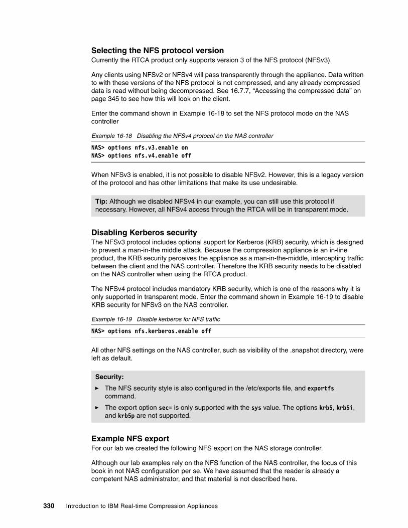
Selecting the NFS protocol versionCurrently the RTCA product only supports version 3 of the NFS protocol (NFSv3).
Any clients using NFSv2 or NFSv4 will pass transparently through the appliance. Data written to with these versions of the NFS protocol is not compressed, and any already compressed data is read without being decompressed. See 16.7.7, “Accessing the compressed data” on page 345 to see how this will look on the client.
Enter the command shown in Example 16-18 to set the NFS protocol mode on the NAS controller
Example 16-18 Disabling the NFSv4 protocol on the NAS controller
NAS> options nfs.v3.enable onNAS> options nfs.v4.enable off
When NFSv3 is enabled, it is not possible to disable NFSv2. However, this is a legacy version of the protocol and has other limitations that make its use undesirable.
Disabling Kerberos securityThe NFSv3 protocol includes optional support for Kerberos (KRB) security, which is designed to prevent a man-in-the middle attack. Because the compression appliance is an in-line product, the KRB security perceives the appliance as a man-in-the-middle, intercepting traffic between the client and the NAS controller. Therefore the KRB security needs to be disabled on the NAS controller when using the RTCA product.
The NFSv4 protocol includes mandatory KRB security, which is one of the reasons why it is only supported in transparent mode. Enter the command shown in Example 16-19 to disable KRB security for NFSv3 on the NAS controller.
Example 16-19 Disable kerberos for NFS traffic
NAS> options nfs.kerberos.enable off
All other NFS settings on the NAS controller, such as visibility of the .snapshot directory, were left as default.
Example NFS exportFor our lab we created the following NFS export on the NAS storage controller.
Although our lab examples rely on the NFS function of the NAS controller, the focus of this book in not NAS configuration per se. We have assumed that the reader is already a competent NAS administrator, and that material is not described here.
Tip: Although we disabled NFSv4 in our example, you can still use this protocol if necessary. However, all NFSv4 access through the RTCA will be in transparent mode.
Security:
� The NFS security style is also configured in the /etc/exports file, and exportfs command.
� The export option sec= is only supported with the sys value. The options krb5, krb5i, and krb5p are not supported.
330 Introduction to IBM Real-time Compression Appliances

For more information about NAS features and administration, see the Redbooks publication, IBM System Storage N series Software Guide, SG24-7129.
Our sample NFS export is shown in Example 16-20. The name “myclient” was the hostname of our UNIX client used to mount the NFS export.
Example 16-20 Sample NFS export
NAS> exportfs/vol/nfs_vol1 sec=sys,rw=myclient,root=myclient,nosuid
For the purposes of our lab examples, we populated the sample NFS export with a variety of file types, including data extracted into multiple files from the Freebase database, which was obtained from the following website:
http://download.freebase.com/datadumps/
Existing dataAt the start of our lab the NFS export contained some data, as shown in Example 16-21.
Example 16-21 Sample NFS export at start of the lab
N5600-B> df -Sh /vol/cifs_vol1Filesystem used compressed a-sis %saved/vol/nfs_vol1/ 11GB 0GB 0GB 0%
The sample export did not contain any NAS deduplicated or NAS compressed data.
Existing snapshot copiesThere were also a number of existing snapshot copies, as shown in Example 16-22.
Example 16-22 Existing snapshot copies at start of the lab
N5600-B*> snap list
Volume nfs_vol1working...
%/used %/total date name---------- ---------- ------------ -------- 11% (11%) 2% ( 2%) Oct 18 12:00 hourly.0 20% (11%) 4% ( 2%) Oct 18 08:00 hourly.1 20% ( 0%) 4% ( 0%) Oct 18 00:00 nightly.0 20% ( 0%) 4% ( 0%) Oct 17 20:00 hourly.2 20% ( 0%) 4% ( 0%) Oct 17 16:00 hourly.3 27% (11%) 6% ( 2%) Oct 17 12:00 hourly.4 33% (11%) 8% ( 2%) Oct 17 08:00 hourly.5 33% ( 0%) 9% ( 0%) Oct 17 00:00 nightly.1
There had been little change to the sample volume, so the percentage changed was also very low.
Dummy workloadTo test the effect of enabling RTCA compression with a running NFS workload, we configured a UNIX system to continuously run a Filebench benchmark on the sample export.
Chapter 16. File serving solutions 331

The Filebench product was downloaded from the following website:
http://sourceforge.net/apps/mediawiki/filebench/
Note that this was not intended as a performance benchmark, and was chosen as a simple way to provide a continuous NFS workload during our implementation.
16.7.2 Configuring the RTCA product
This section assumes that the initial configuration of the RTCA product has been completed.
AssumptionsWe assume that the RTCA’s management port (IP addresses), network (bonds and bridges), and storage (NAS controllers) have already been configured.
Authentication and authorizationTo enable the RTCA product to proxy the NFS client access. you will need to add it to the NFS exports permissions on the NAS controller. This will allow the RTCA to list the available NFS exports, and is later used by the compression filters and Compression Accelerator function.
Follow these steps to configure the host access parameters for the sample NFS export:
1. Log in to the NAS administrative interface (CLI examples shown here)
2. Add the IP addresses for the RTCA bridge interfaces to the /etc/hosts file, as shown in Example 16-23
a. Review the contents of the file
b. Append the bridge IP addresses and logical names to the file
c. Review the changes
Example 16-23 Add the RTCA bridge addresses to the host file on the NAS controller
N5600-B> rdfile /etc/hosts
#Auto-generated by setup Tue Sep 6 12:47:40 GMT 2011127.0.0.1 localhost10.0.0.1 N5600-B N5600-B-e0a10.0.0.100 myclient
N5600-B> wrfile -a /etc/hosts 10.0.0.10 rtca2-br0N5600-B> wrfile -a /etc/hosts 10.0.0.11 rtca2-br1N5600-B> wrfile -a /etc/hosts 10.0.0.12 rtca1-br0N5600-B> wrfile -a /etc/hosts 10.0.0.13 rtca1-br1
N5600-B> rdfile /etc/hosts
#Auto-generated by setup Tue Sep 6 12:47:40 GMT 2011127.0.0.1 localhost
Access:
� Here we are configuring the NAS controller to allow NFS access from the RTCA product.
� This is opposite the CIFS example, where we configured the RTCA with the correct user credentials to access the NAS controller.
332 Introduction to IBM Real-time Compression Appliances

10.0.0.1 N5600-B N5600-B-e0a10.0.0.100 myclient10.0.0.10 rtca2-br010.0.0.11 rtca2-br110.0.0.12 rtca1-br010.0.0.13 rtca1-br1
Obviously, you will need to replace the 10.0.0.X addresses with the correct IP addresses for the bridges on your RTCA product.
3. Add the logical names for the RTCA bridge interfaces to the /etc/netgroups file, as shown in Example 16-24.
Later, this will simplify the configuration of the NFS host access parameters:
a. Review the contents of the file.
b. Append the bridge logical names to the file (in the format shown).
c. Review the changes.
Example 16-24 Add RTCA bridge names to the netgroup file on the NAS
N5600-B> rdfile /etc/netgroup
/etc/netgroup: No such file or directory
N5600-B> wrfile -a /etc/netgroup rtca (rtca1-br0,,) (rtca1-br1,,) (rtca2-br0,,) (rtca2-br1,,)
N5600-B> rdfile /etc/netgroup
rtca (rtca1-br0,,) (rtca1-br1,,) (rtca2-br0,,) (rtca2-br1,,)
4. Add the RTCA bridge interfaces to the export parameters, as shown in Example 16-25:
a. Review the current export parameters.
b. Update the export parameters.
Note that the @rtca field refers to the netgroup configured in Example 16-24.
c. Review the changes.
Example 16-25 Add the RTCA netgroup entry to the sample NFS export parameters
N5600-B> exportfs -q /vol/nfs_vol1
/vol/nfs_vol1 -sec=sys,(ruleid=1),rw=myclient,root=myclient,nosuid
N5600-B>exportfs -p sec=sys,rw=myclient:@rtca,root=myclient:@rtca,nosuid /vol/nfs_vol1
N5600-B> exportfs -q /vol/nfs_vol1 /vol/nfs_vol1 -sec=sys,(ruleid=2),rw=myclient:@rtca,root=myclient:@rtca,nosuid
Ping: If you decide to check your configuration, use the ping command to test the bridge interfaces from the NAS controller. Be aware that you will NOT be able to ping the active bridge interface.
Chapter 16. File serving solutions 333

You need not be concerned with the (ruleid=X) in the example. This indicates that the NAS controller’s access cache rule that represents this particular set of host access parameters.
At this point the RTCA product will have sufficient authorization to access and update (compress) the contents of the sample NFS export.
We have assumed that the Storage interfaces (IP address, and so on) for the NAS controller have already been defined.
16.7.3 Storage compression mode
When a storage system is defined to the RTCA it is assigned a compression mode. This controls whether the system leaves the new data unchanged (transparent mode) or compresses all new data by default (compressed mode). In our lab we initially set the storage controllers to transparent mode.
Transparent modeThis is the default mode when a new storage controller is defined to the RTCA. In this mode, no new user access is compressed, or uncompressed, by default. Note however, that all CIFS (and NFS) traffic is already passing through the RTCA product in transparent mode. Follow these steps to view the list of available NFS (and CIFS) shares on the NAS controller:
1. Log in to the RTCA web interface
2. In the left-hand menu, under Configuration, select Storage.
3. In the Storage systems view, select your NAS controller.
a. This will update the display to show the available CIFS shares, as shown in Figure 16-23.
Figure 16-23 Viewing the available NFS exports in transparent mode
For the example NFS export in Figure 16-23, in storage transparent mode, the two check boxes have the following effect:
� Left box - Compression filter:
– Unchecked = No compression or decompression
– Checked = New data is compressed, existing data is uncompressed
� Right box - No new compression (only visible when left box is checked):
– Unchecked = New data IS compressed, existing data is uncompressed
– Checked = New data is NOT compressed, existing data is uncompressed
See “Compressing new data” on page 312 for a description of how to configure the compression filter to compress new data.
334 Introduction to IBM Real-time Compression Appliances
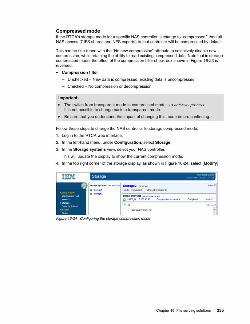
Compressed modeIf the RTCA’s storage mode for a specific NAS controller is change to “compressed,” then all NAS access (CIFS shares and NFS exports) to that controller will be compressed by default.
This can be fine-tuned with the “No new compression” attribute to selectively disable new compression, while retaining the ability to read existing compressed data. Note that in storage compressed mode, the effect of the compression filter check box shown in Figure 16-23 is reversed.
� Compression filter
– Unchecked = New data is compressed, existing data is uncompressed
– Checked = No compression or decompression
Follow these steps to change the NAS controller to storage compressed mode:
1. Log in to the RTCA web interface.
2. In the left-hand menu, under Configuration, select Storage.
3. In the Storage systems view, select your NAS controller.
This will update the display to show the current compression mode.
4. In the top right corner of the storage display, as shown in Figure 16-24, select [Modify].
Figure 16-24 Configuring the storage compression mode
Important:
� The switch from transparent mode to compressed mode is a one-way process. It is not possible to change back to transparent mode.
� Be sure that you understand the impact of changing this mode before continuing.
Chapter 16. File serving solutions 335

5. The “Modify storage parameters” dialog box will appear, as shown in Figure 16-25:
a. Select “Compressed” in the Compression mode field.
Note that the CIFS user credentials are not required to process NFS exports.
b. Click Apply.
Figure 16-25 Select the compression mode
6. The dialog box will update with a warning message, as shown in Figure 16-26.
a. Be sure to read the warning message before continuing with this process.
Also note that the “No new compression” field appears (NNC), and cannot be changed from “On”. We will modify this field later to enable compression.
Again, the CIFS user credentials are not required to process NFS exports.
b. Click Apply.
Figure 16-26 The compression mode warning message
336 Introduction to IBM Real-time Compression Appliances
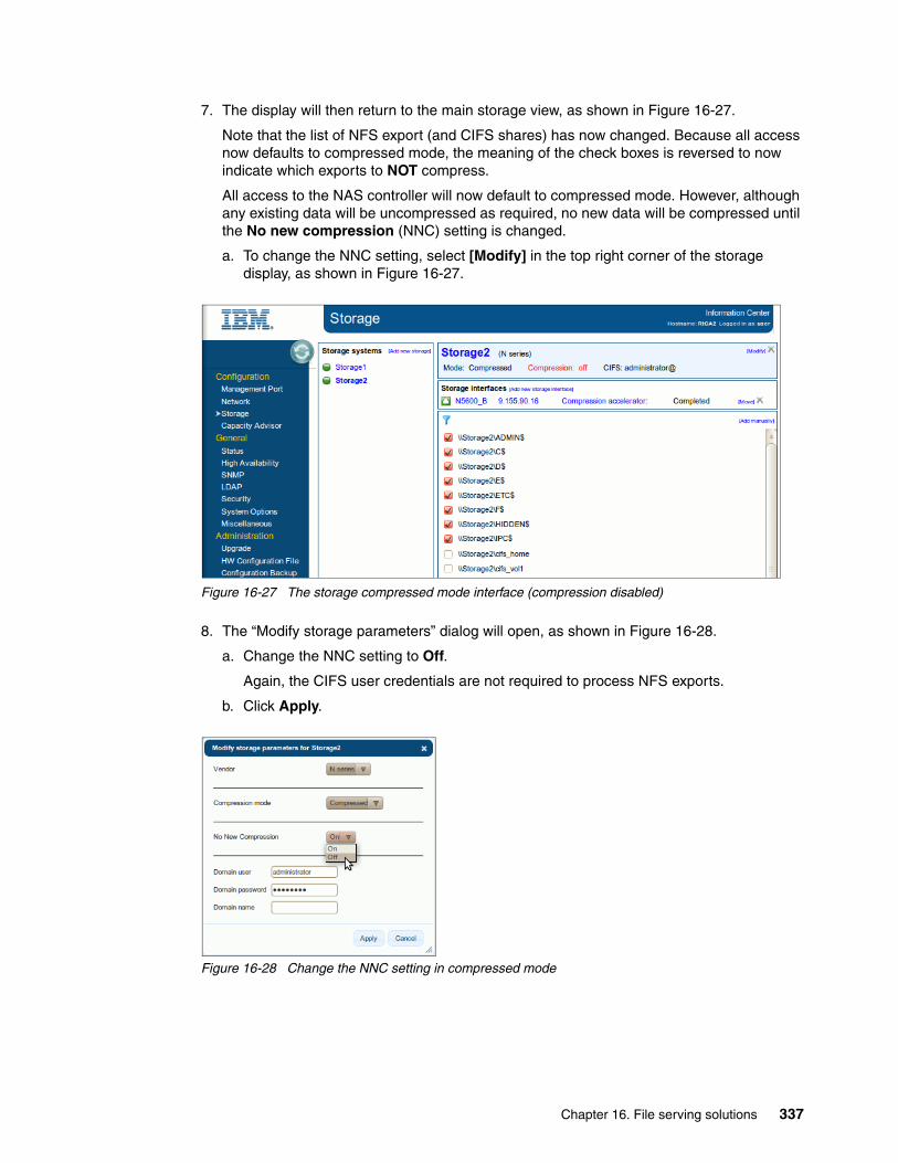
7. The display will then return to the main storage view, as shown in Figure 16-27.
Note that the list of NFS export (and CIFS shares) has now changed. Because all access now defaults to compressed mode, the meaning of the check boxes is reversed to now indicate which exports to NOT compress.
All access to the NAS controller will now default to compressed mode. However, although any existing data will be uncompressed as required, no new data will be compressed until the No new compression (NNC) setting is changed.
a. To change the NNC setting, select [Modify] in the top right corner of the storage display, as shown in Figure 16-27.
Figure 16-27 The storage compressed mode interface (compression disabled)
8. The “Modify storage parameters” dialog will open, as shown in Figure 16-28.
a. Change the NNC setting to Off.
Again, the CIFS user credentials are not required to process NFS exports.
b. Click Apply.
Figure 16-28 Change the NNC setting in compressed mode
Chapter 16. File serving solutions 337
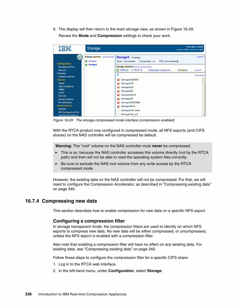
9. The display will then return to the main storage view, as shown in Figure 16-29.
Review the Mode and Compression settings to check your work.
Figure 16-29 The storage compressed mode interface (compression enabled)
With the RTCA product now configured in compressed mode, all NFS exports (and CIFS shares) on the NAS controller will be compressed be default.
However, the existing data on the NAS controller will not be compressed. For that, we will need to configure the Compression Accelerator, as described in “Compressing existing data” on page 340.
16.7.4 Compressing new data
This section describes how to enable compression for new data on a specific NFS export.
Configuring a compression filterIn storage transparent mode, the compression filters are used to identify on which NFS exports to compress new data. No new data will be either compressed, or uncompressed, unless the NFS export is enabled with a compression filter.
Also note that enabling a compression filter will have no effect on any existing data. For existing data, see “Compressing existing data” on page 340.
Follow these steps to configure the compression filter for a specific CIFS share:
1. Log in to the RTCA web interface.
2. In the left-hand menu, under Configuration, select Storage.
Warning: The “root” volume on the NAS controller must never be compressed.
� This is so, because the NAS controller accesses this volume directly (not by the RTCA path) and then will not be able to read the operating system files correctly.
� Be sure to exclude the NAS root volume from any write access by the RTCA compressed mode.
338 Introduction to IBM Real-time Compression Appliances

3. In the Storage systems view, select your NAS controller.
This will update the display to show the available NFS exports, as shown in Figure 16-30.
4. Select the check box beside the export that you wish to compress (for new data).
– This will cause a second check box to appear (for the “No new compression” option).– Do not select this check box.
Figure 16-30 Enabling the compression filter for an NFS export
5. When satisfied with your changes, click Apply at the top of the share list.
This will cause a confirmation dialog box to appear, shown in Figure 16-31.
Figure 16-31 Confirm the new compression filter
6. The display will then update to show the new compression filter.
At this point, any new (or updated) data written to this NFS export will be compressed by the RTCA product.
Chapter 16. File serving solutions 339

Configuring file extensions to excludeThis section describes how to filter the compression engine to exclude specific file types.
Because some data types are either already compressed (for example, GZIP files) or naturally uncompressible (for example, PACS data), they must be excluded from the RTCA compression process.
Follow these steps to configure the file type exclusions:
1. Log in to the RTCA web interface.
2. In the left-hand menu, under Configuration, select Storage.
3. In the Storage systems view, select your NAS controller.
4. In the lower left corner, select File extensions to exclude.
This will open a new dialog box, as shown in Figure 16-32.
Figure 16-32 Configuring file extensions to exclude
5. Update the exclusion list as required.
Then click Apply to save your changes.
From this point, any new data that matches these file extensions will not compressed by the RTCA product.
16.7.5 Compressing existing data
This section describes how to use the Compression Accelerator to compress the existing data on an NFS export or group of exports. Setting a NFS share to compressed mode (see “Compressing new data” on page 338) will only compress the new or changes data on the share. Any existing data will remain uncompressed until it is updated by the client. The RTCA product provides a “Compression Accelerator” feature to compress the existing data independent of any NAS client access.
Compression acceleratorThis feature will read, compress, and rewrite the existing data on the nominated NFS export. This accelerates the space savings that are delivered by the data compression. Any subsequent client access will then be to the compressed form of the data.
An important difference between the compressed share setting and the Compression Accelerator, is that the compression setting is ongoing, while the CA process is typically only run once to process the existing data.
340 Introduction to IBM Real-time Compression Appliances

Follow these steps to configure the Compression Accelerator for the sample NFS export:
1. Log in to the RTCA web interface.
2. In the left-hand menu, under Configuration, select Storage.
3. In the Storage systems view, select your NAS controller.
Ensure that the icon beside your storage controller is green (as shown in Figure 16-33).
– This indicates that this is the active RTCA node for that storage interface.
– If not, then you need to check the other RTCA node, or investigate why the NAS storage interface is offline.
Figure 16-33 Enable the Compression Accelerator for an NFS export
4. In the Storage Interfaces view, select Compression Accelerator.
This will open a new panel, as shown in Figure 16-34.
5. In the Settings tab, enter the following information:
– Scheduling = (set as required, for example: 17:00 - 20:00)
– CIFS username = (not required for NFS access)
– CIFS password = (not required for NFS access)
– CIFS domain = (not required for NFS access)
– Policy = (if desired, restrict the CA process by file size, timestamp, and so on)
– Directories to ignore = (typically used to prevent the CA from processing snapshot copies)
– Maximum total throughput (MB/sec) = (if desired, throttle the CA process to a specified throughput)
– Amount of changes = (if desired, stop the CA process after specified amount of change within the time frame)
– Free space threshold = (if desired, stop the CA process if the free space on the share reaches this limit)
– Interval between files (ms) = (if desired, throttle the CA process by imposing a delay between file processing)
6. Click the Apply Changes button.
Chapter 16. File serving solutions 341

Figure 16-34 Configure the Compression Accelerator
7. Skip the Shares tab.
8. In the Exports tab (shown in Figure 16-35), select the NFS export to compress.
9. Click the Update List button.
Figure 16-35 Select an NFS export for the Compression Accelerator
10.In the Status tab (shown in Figure 16-36), review the current status.
Click Start to initiate the CA process.
This will update the display to show the files being compressed.
342 Introduction to IBM Real-time Compression Appliances

Figure 16-36 Start the Compression Accelerator
11.In the Log tab (shown in Figure 16-37), review the summary of the CA process.
Figure 16-37 Review the log file for the Compression Accelerator
After the Compression Accelerator process has finished successfully, all of the existing data on the NFS export will be in a compressed format.
Existing data in compressed modeAt the end of our RTCA lab, all of the data on the NFS export had been compressed.
The reduction in used capacity is shown in Example 16-26. Note that the compression ratio is representative of our particular data set. You need to test the RTCA product in your own environment to determine the estimated capacity saving with your data set.
Example 16-26 Example data capacity after compression
N5600-B> df -Sh /vol/nfs_vol1Filesystem used compressed a-sis %saved/vol/nfs_vol1/ 2184MB 0MB 0MB 0%
After the RTCA compression, and Compression Accelerator, had completed there was a large change in the Active File System (IBM AFS™) versus the snapshot backup. In our example, this was still below the 20% snapshot reserve, so it had no impact on the available file system capacity.
Important: In a production environment, you must consider the impact of RTCA compression on the snapshot reserve and usable volume capacity. It might be prudent to delete some or all snapshots prior to running the Compression Accelerator.
Chapter 16. File serving solutions 343

16.7.6 Enabling NAS deduplication
One of the features of the RTCA product is that the compressed data is written in a manner that is compatible with subsequent deduplication on the NAS controller. This allows us to use the storage efficiency benefits of both RTCA compression and NAS deduplication. Example 16-27 shows how to enable NAS deduplication on our sample volume.
Example 16-27 Enabling deduplication on the NAS controller
NAS> sis on /vol/nfs_vol1
SIS for "/vol/nfs_vol1" is enabled.Already existing data could be processed by running "sis start -s /vol/nfs_vol1".
NAS> sis start -s /vol/nfs_vol1
The file system will be scanned to process existing data in /vol/nfs_vol1.This operation may initialize related existing metafiles.Are you sure you want to proceed (y/n)? yThe SIS operation for "/vol/nfs_vol1" is started.
[wait for the deduplication process to finish...]
NAS> df -Sh /vol/nfs_vol1Filesystem used compressed a-sis %saved/vol/nfs_vol1/ 646MB 0MB 1542MB 70%
Of course, on the NFS client, the compressed data is still readable in its original form. The file system capacity is reported correctly, as shown in Example 16-28.
Example 16-28 Viewing the logical data capacity on the CIFS client
user@host:/nfs/nfs_vol1$ du -h .
[directoy listing not shown]
...
...9.4G
However, the true used capacity can be seen on the client with the df command, as shown in Example 16-29.
Example 16-29 Viewing the physical data capacity on the CIFS client
user@host:/nfs/nfs_vol1$ df -m /nfs/nfs_vol1
Filesystem 1M-blocks Used Available Use% Mounted onnas2:/vol/nfs_vol1 40960 647 40314 2% /nfs/nfs_vol1
The slight variation in reported capacity is due to the different ways that the NAS controller and UNIX report disk usage.
344 Introduction to IBM Real-time Compression Appliances

16.7.7 Accessing the compressed data
This section describes the NFS client’s view of the NAS data after it has been compressed by the RTCA product.
Accessing data through the compressed pathWhen the RTCA is configured correctly, the NFS client can access the compressed data exactly as expected. The file contents, and all file meta-data, are apparently unchanged.
Example 16-30 shows a file that was accessed from a compressed (and deduplicated) NFS export.
Example 16-30 Correct access to the compressed data
stevpem@tiamut:/$ file /nfs/nfs_vol1/FreeBase/data.aaaa
/nfs/nfs_vol1/FreeBase/data.aaaa: UTF-8 Unicode English text
stevpem@tiamut:/$ head --lines=1 /nfs/nfs_vol1/FreeBase/data.aaaa
/m/010001k/common/topic/notable_types/music/track
Accessing data through the transparent pathIf the RTCA is configured incorrectly, the NFS client will not be able to access the compressed data. The file contents will appear corrupt to the NFS client.
For the purpose of demonstration only, the volume containing the sample NFS export was duplicated on the NAS controller by the NAS volcopy command. This volume contained the RTCA compressed data, but was configured for transparent access, bypassing the RTCA product’s decompression algorithms.
The result of incorrectly accessing the compressed data can be seen in Example 16-31.
Example 16-31 Incorrect access to the compressed data
stevpem@tiamut:/nfs/nfs_vol2$ file /nfs/nfs_vol2/data.aaaa
/nfs/nfs_vol2/data.aaaa: data
stevpem@tiamut:/$ head --bytes=100 /nfs/nfs_vol2/data.aaaa
CMPt?;?Qq$???a??????x8??????????????????????????????????????????????????????????
You will notice that Example 16-31 shows the same file as in Example 16-30, but now it is unusable. The first three characters of the file, “CMP” identify this as an RTCA compressed file.
However, any files that had been excluded from compression (for example, *.zip files) will still appear as normal, because they were not processed by the RTCA product.
Note: During normal operations, access to the compressed data should always be through the RTCA compressed path. However, this is the way the files will appear if the RTCA is unavailable (for example, at a DR site with no local RTCA product).
Chapter 16. File serving solutions 345

16.7.8 Calculating the compression ratio
Although it is not the intent of this book to provide guidance regarding RTCA performance or compression ratios, Table 16-2 shows the compression ratio from our lab environment.
Table 16-2 Example compression ratios (with compression and deduplication)
Obviously, the RTCA performance and compression ratios will vary depending on the NAS hardware platform and specific data set used. We encourage you to test the product in your environment before any production implementation.
Original size After RTCA After NAS dedupe
NFS_VOL1 8764 MB 2184 MB 646 MB
Approx 75% reduction Approx 70% reduction
Total 93% reduction
346 Introduction to IBM Real-time Compression Appliances

Part 4 Appendixes
In this part of the book, we provide information to aid in troubleshooting the IBM Real-time Compression Appliance.
Part 4
© Copyright IBM Corp. 2013. All rights reserved. 347

348 Introduction to IBM Real-time Compression Appliances

Appendix A. Troubleshooting
This appendix is designed to help you troubleshoot some small issues that you might have with your IBM Real-time Compression Appliance. It is complementary with the IBM Real-time Compression Appliances Version 4 Release 1 Troubleshooting Guide, GA32-2218.
In this appendix, we cover the following topics:
� Mismatch of UEFI/IMM resolution� Omitted CIFS credentials� Upgrading the RTCA firmware
A
© Copyright IBM Corp. 2013. All rights reserved. 349
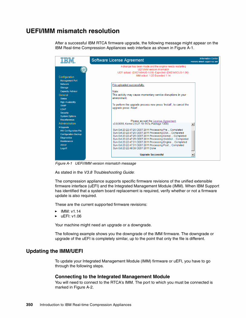
UEFI/IMM mismatch resolution
After a successful IBM RTCA firmware upgrade, the following message might appear on the IBM Real-time Compression Appliances web interface as shown in Figure A-1.
Figure A-1 UEFI/IMM version mismatch message
As stated in the V3.8 Troubleshooting Guide:
The compression appliance supports specific firmware revisions of the unified extensible firmware interface (uEFI) and the Integrated Management Module (IMM). When IBM Support has identified that a system board replacement is required, verify whether or not a firmware update is also required.
These are the current supported firmware revisions:
� IMM: v1.14� uEFI: v1.06
Your machine might need an upgrade or a downgrade.
The following example shows you the downgrade of the IMM firmware. The downgrade or upgrade of the uEFI is completely similar, up to the point that only the file is different.
Updating the IMM/UEFI
To update your Integrated Management Module (IMM) firmware or uEFI, you have to go through the following steps.
Connecting to the Integrated Management ModuleYou will need to connect to the RTCA’s IMM. The port to which you must be connected is marked in Figure A-2.
350 Introduction to IBM Real-time Compression Appliances
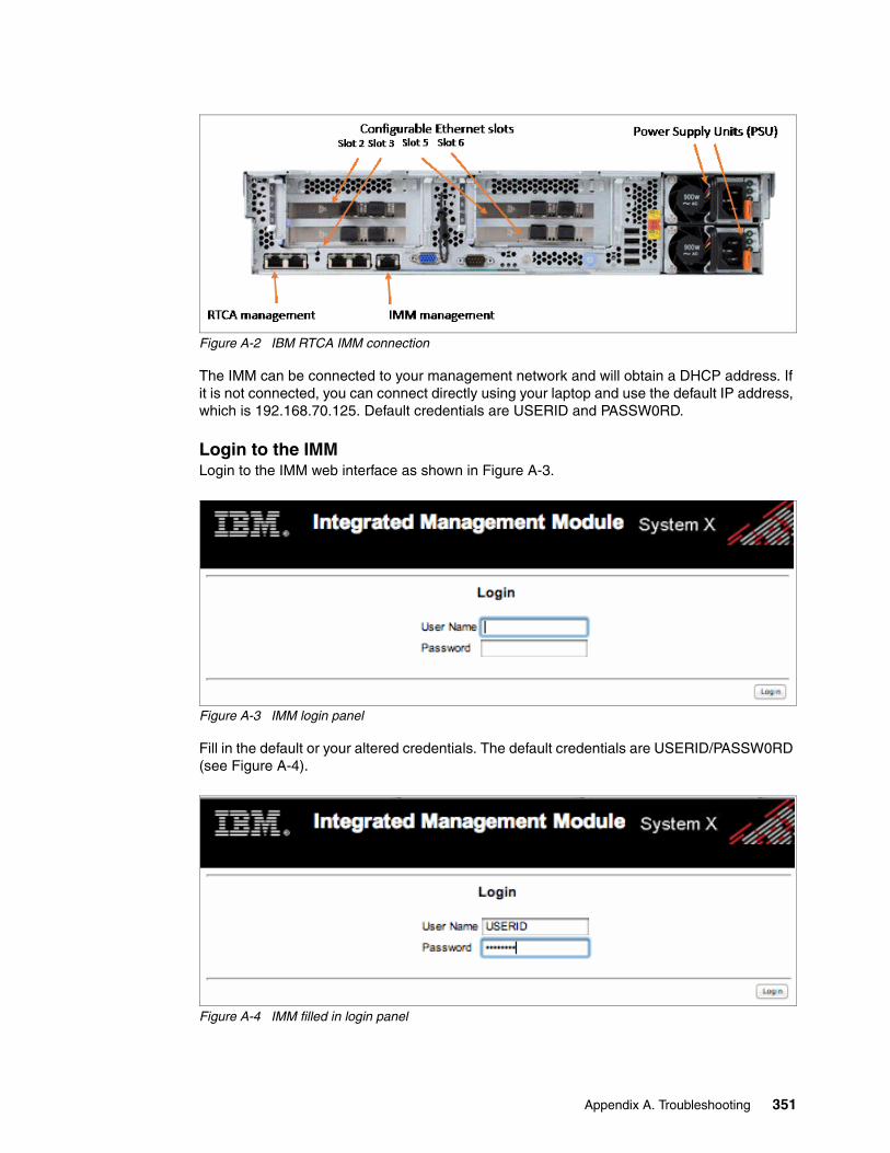
Figure A-2 IBM RTCA IMM connection
The IMM can be connected to your management network and will obtain a DHCP address. If it is not connected, you can connect directly using your laptop and use the default IP address, which is 192.168.70.125. Default credentials are USERID and PASSW0RD.
Login to the IMMLogin to the IMM web interface as shown in Figure A-3.
Figure A-3 IMM login panel
Fill in the default or your altered credentials. The default credentials are USERID/PASSW0RD (see Figure A-4).
Figure A-4 IMM filled in login panel
Appendix A. Troubleshooting 351

After the login, you will get the following Status display (Figure A-5).
Figure A-5 IMM Status panel
Checking vital product dataIn the Vital Product Data tab (Figure A-6), which you can find under the Monitors tab, you can find the firmware versions of the IMM and uEFI under the Firmware VPD caption.
Figure A-6 Vital Product Data tab
352 Introduction to IBM Real-time Compression Appliances

These are the supported firmware levels for the IMM and uEFI:
� IMM: v1.14
� uEFI: v1.06
They correspond to the following Version Strings:
� IMM: YUOO73M
� uEFI: D6E145C
Figure A-7 shows us that in our case only the IMM is not the supported version, it is a newer version. This can be due to the fact that the system board has been replaced and the replacement part was shipped with a different firmware level.
Figure A-7 Firmware VPD
Updating firmwareTo solve the issue, go to the Firmware update submenu under the Tasks tab in the menu as shown in Figure A-8.
Figure A-8 Firmware update panel
Appendix A. Troubleshooting 353
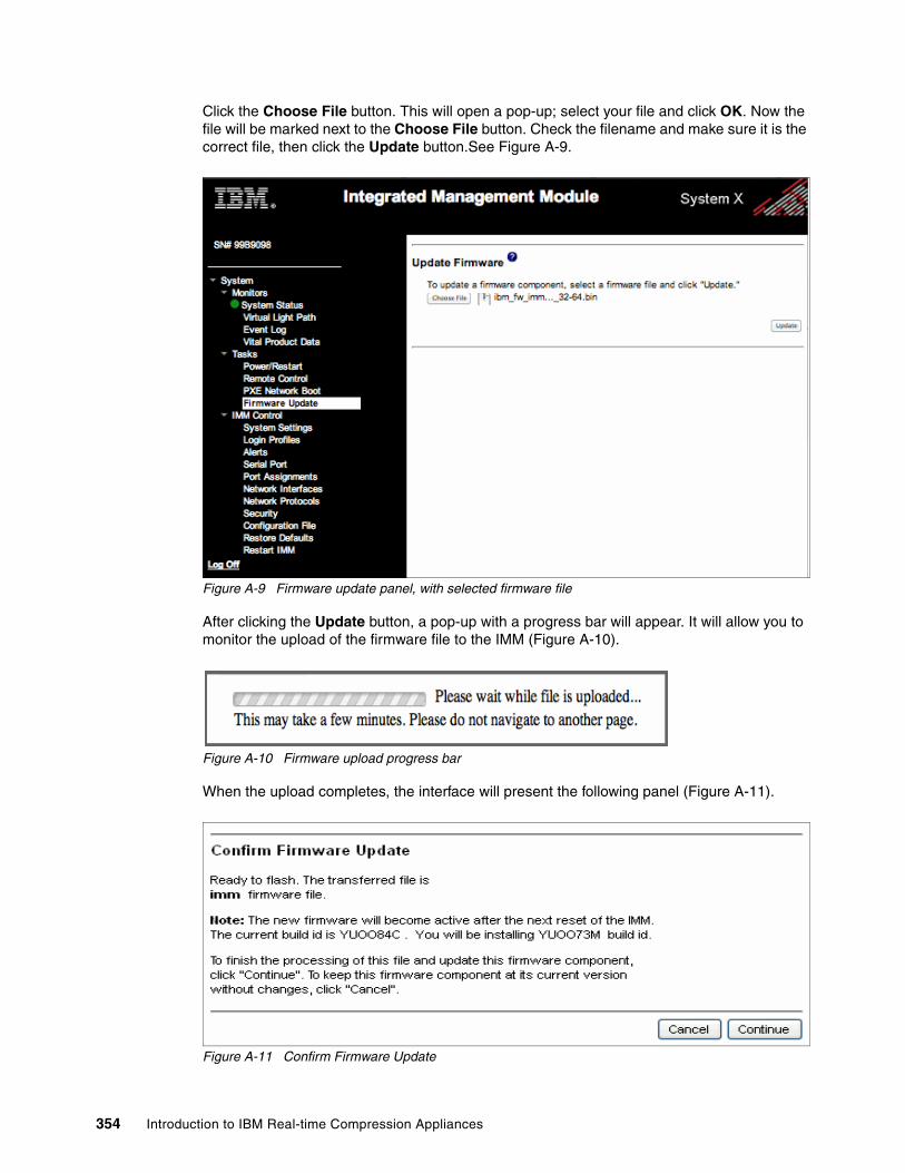
Click the Choose File button. This will open a pop-up; select your file and click OK. Now the file will be marked next to the Choose File button. Check the filename and make sure it is the correct file, then click the Update button.See Figure A-9.
Figure A-9 Firmware update panel, with selected firmware file
After clicking the Update button, a pop-up with a progress bar will appear. It will allow you to monitor the upload of the firmware file to the IMM (Figure A-10).
Figure A-10 Firmware upload progress bar
When the upload completes, the interface will present the following panel (Figure A-11).
Figure A-11 Confirm Firmware Update
354 Introduction to IBM Real-time Compression Appliances

The Firmware Update tool will recognize the uploaded file as an IMM update file and will recognize the “Version String” it contains. Just click the Continue button to process the firmware component.
During the update, you will be able to monitor the process on the web interface as shown in Figure A-12.
Figure A-12 Firmware upgrade progress
When the update completes, you will be prompted to restart the IMM (Figure A-13).
Figure A-13 Firmware update successful
Just click the OK button. This will take you to the Firmware Update tab. To restart the IMM, select the Restart IMM tab of the IMM Control sub menu and click the Restart button (Figure A-14).
Figure A-14 Restart IMM
Appendix A. Troubleshooting 355
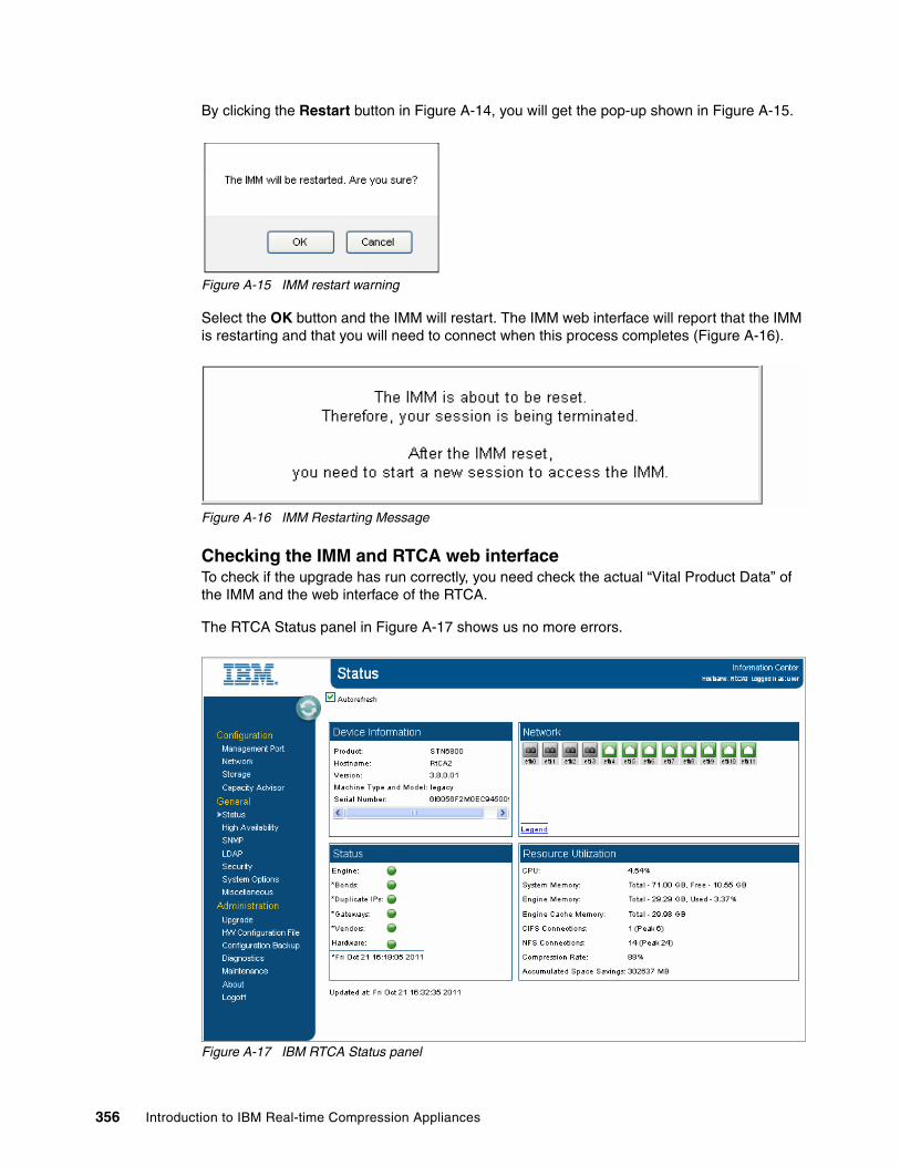
By clicking the Restart button in Figure A-14, you will get the pop-up shown in Figure A-15.
Figure A-15 IMM restart warning
Select the OK button and the IMM will restart. The IMM web interface will report that the IMM is restarting and that you will need to connect when this process completes (Figure A-16).
Figure A-16 IMM Restarting Message
Checking the IMM and RTCA web interfaceTo check if the upgrade has run correctly, you need check the actual “Vital Product Data” of the IMM and the web interface of the RTCA.
The RTCA Status panel in Figure A-17 shows us no more errors.
Figure A-17 IBM RTCA Status panel
356 Introduction to IBM Real-time Compression Appliances

This implies that the upgrade was successful. We will check the IMM web interface once more to check the “Vital Product Data” (Figure A-18).
Figure A-18 Vital Product Data after Firmware update
The IMM “Version String” now is “YUOO73M”, which is the supported one, so the message in the RTCA web interface will not appear.
Omitted CIFS credentials
After upgrading to the new IBM RTCA software, you might lose the CIFS credentials. The credentials in the Storage tab are used to list the CIFS shares, so your compression will not be influenced, but the IBM RTCA will not be able to list new CIFS shares. To list new CIFS shares, simply re-enter the CIFS credentials (see Figure A-19).
Figure A-19 CIFS credential Storage
Appendix A. Troubleshooting 357

Insert the credentials again (see Figure A-20): login, password, and domain, as shown in Appendix A-20, “CIFS Credential insert” on page 358.
Figure A-20 CIFS Credential insert
Upgrading the RTCA firmware
Periodically, the compression appliance software might require upgrading. In this case, instructions are provided regarding the best time and procedure for the upgrade.
Currently, minor software release upgrades can be implemented without stopping the compression appliance. For example, software updates for the web interface can be performed without stopping the compression engine. Upgrades to other parts of the software might require restarting the compression engine or rebooting the compression appliance.
We also advise that you coordinate the firmware update with IBM Support before you perform a software upgrade.
Attention: The system must be running V3.9 or later before an upgrade to V4,1.
This upgrade will reboot the system.
358 Introduction to IBM Real-time Compression Appliances

To perform a firmware update, follow these steps:
1. To upgrade the software release, save the software upgrade file locally.
2. Click Upgrade to open the Software Upgrade page.
3. Click Browse and locate the upgrade file.
4. Click Upgrade.
After the upgrade file finishes uploading to the appliance, click License Agreement to open up the license agreement text. Select the appropriate language from the drop down menu to read the agreement in other languages. Click the I agree button to accept the agreement, and click Install to start the upgrade.
The new software will now be installed. When the installation is complete, a success message is displayed. If a compression engine restart or a compression appliance reboot are required, an appropriate warning will be displayed.
The following web interface panels resulted from the upgrade from version 3.8.0.02 to 4.1.0.03. We did follow these steps:
1. Perform firmware level check, as shown in Figure A-21 on page 360.
2. Back up current configuration, as shown in Figure A-22 on page 360.
3. Upgrade to 3.9.1.04:
a. Select the firmware previous downloaded from IBM site, as shown in figures Figure A-23 on page 361 and Figure A-24 on page 362.
b. Agree with the license agreement, as shown in Figure A-25 on page 362.
c. Wait until the end of the task, as shown in Figure A-26 on page 363 and Figure A-27 on page 363.
d. Reboot the RTCA, as shown in Figure A-28 on page 364 and Figure A-29 on page 364.
4. Upgrade from 3.9.1.04 to 4.1.0.01:
a. Select the firmware previous downloaded from IBM site, as shown in Figure A-30 on page 365.
b. Agree with the license agreement.
c. Wait until the end of the task.
d. RTCA will reboot itself after the firmware upgrade.
5. Upgrade from 4.1.0.01 to 4.1.0.03.As shown in Figure A-31 on page 365:
a. Select the firmware previous downloaded from IBM site.
b. Agree with the license agreement.
c. Wait until the end of the task.
d. Reboot the RTCA.
Appendix A. Troubleshooting 359

In the status panel (Figure A-21), there is information about the firmware level.
Figure A-21 Firmware Version on the Status Panel
On the configuration backup panel (Figure A-22), you can save the current configuration or restore a previous one. If the restore factory defaults options are enabled on the system setting, you can restore the factory defaults from this panel.
Figure A-22 Configuration backup
360 Introduction to IBM Real-time Compression Appliances
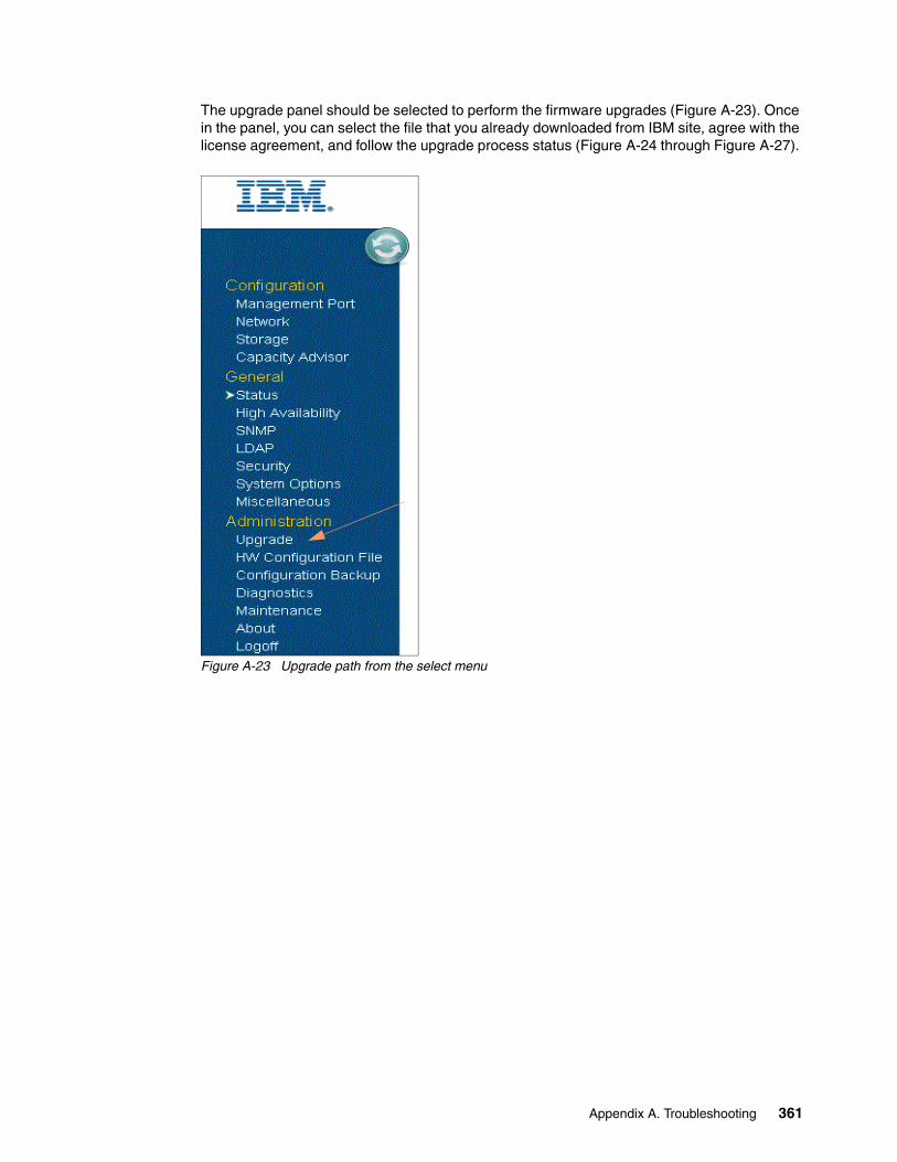
The upgrade panel should be selected to perform the firmware upgrades (Figure A-23). Once in the panel, you can select the file that you already downloaded from IBM site, agree with the license agreement, and follow the upgrade process status (Figure A-24 through Figure A-27).
Figure A-23 Upgrade path from the select menu
Appendix A. Troubleshooting 361

Figure A-24 Upgrade file path
Figure A-25 Perform upgrade
Select the file
Click on license Agreement
362 Introduction to IBM Real-time Compression Appliances

Figure A-26 Upgrade status
Figure A-27 Finished status and reboot needed
Appendix A. Troubleshooting 363

After a successful end of the firmware upgrade, select the maintenance panel. Type in the login password and the reason for the reboot (Figure A-28).
Figure A-28 Reboot
You must accept the confirmation (Figure A-29).
Figure A-29 Reboot confirmation
364 Introduction to IBM Real-time Compression Appliances

The panels for file selection of firmware for level 4.1.0.01 and 4.1.0.03 are shown in Figure A-30 and Figure A-31.
Figure A-30 Upgrade from 3.9.1.04 to 4.1.0.01
Figure A-31 Upgrade from 4.1.0.01 to 4.1.0.03
Appendix A. Troubleshooting 365
Additional troubleshooting resources
For additional information about RTCA troubleshooting, see the following online resources:
� IBM Real-time Compression Appliances V4.1.0.03 Release Notes:
http://www-304.ibm.com/support/docview.wss?uid=ssg1S7003976&aid=1
� IBM Real-time Compression Appliances Version 4 Release 1 Troubleshooting Guide:
http://pic.dhe.ibm.com/infocenter/rtca/rtcaic/topic/com.ibm.storage.rtca.help.doc/GA32-2218-01.pdf
366 Introduction to IBM Real-time Compression Appliances

ronyms
ACL Access Control List
BPDU Bridge Protocol Data Unit
CLI Command Line Interface
DBCS Double-Byte Character Set
DNFS Direct NFS
DR Disaster Recovery
DSA Dynamic System Analysis
ESCC European Storage Competence Center
GUI Graphical User Interface
HA High Availability
I/O Input/Output
IBM International Business Machines Corporation
ILM Information Life-cycle Management
IPL Initial Program Load
IT Information Technology
ITSO International Technical Support Organization
LACP Link Aggregation Control Protocol
LDAP Lightweight Directory Access Protocol
LSM Link Status Mirroring
MIB Management Information Base
MRM Monitoring and Reporting Manager
MTU Maximum Transmission Unit
NAS Network Attached Storage
NNC No New Compression
RACE Random Access Compression Engine
RTCA IBM Real-time Compression Appliance
SNMP Simple Network Management Protocol
STP Spanning Tree Protocol
TPC Transaction Processing Performance Council
UNC Uniform Naming Convention
UPM Unified Protocol Manager
VIF Virtual Network Interface
VLAN virtual LAN
VM Virtual Machine
Abbreviations and ac
© Copyright IBM Corp. 2013. All rights reserved.
367
368 Introduction to IBM Real-time Compression Appliances

Related publications
The publications listed in this section are considered particularly suitable for a more detailed discussion of the topics covered in this book.
IBM Redbooks publications
The following IBM Redbooks publications provide additional information about the topics in this document. Note that some publications referenced in this list might be available in softcopy only:
� IBM Real-time Compression Appliance Version 4.1, SG24-8112-00
� IBM Real-Time Compression Appliance: New Features in Version 3.9, REDP-4879-00
� IBM Real Time Compression Appliance: What is new in RTCA Version 3.8, REDP-4861-00
� IBM System Storage Solutions Handbook, SG24-5250
� IBM System Storage N series Software Guide, SG24-7129
� IBM System Storage N series Hardware Guide, SG24-7840
� Implementing IBM Storage Data Deduplication Solutions, SG24-7888
� IBM System Storage N series MetroCluster, REDP-4259
� IBM System Storage N series MetroCluster Planning Guide, REDP-4243
� IBM System Storage N series with VMware vSphere 4.1, SG24-7636
� IBM System Storage N series with VMware vSphere 5, SG24-8110-00
You can search for, view, or download Redbooks publications, Redpaper publications, Technotes, draft publications, and Additional materials, as well as order hardcopy Redbooks publications, at this Web site:
ibm.com/redbooks
Other publications
These publications are also relevant as further information sources:
� Real-time Compression Appliances: Installation and Planning Guide, Version 4 Release 1, GI13-1221-04
� Real-time Compression Appliances: Configuration and Administration Guide, Version 4 Release 1, GA32-2217-01
� IBM Real-time Compression Appliances CLI Command Reference Version 4 Release 1, GA32-2219-01
� IBM Real-time Compression Appliances Troubleshooting Guide Version 4 Release 1, GA32-2218-01
� IBM Real-time Compression Appliances Version 4 Release 1- Release Notes, located at:
http://www.ibm.com/support/docview.wss?uid=ssg1S7003976&aid=1
© Copyright IBM Corp. 2013. All rights reserved. 369

Online resources
These Web sites are also relevant as further information sources:
These websites are also relevant as further information sources:
� IBM Real-time Compression:
http://www.ibm.com/systems/storage/solutions/rtc/
� IBM RTCA Support overview:
http://www.ibm.com/storage/support/rtc
� Reducing NAS Costs with Real-time Data Compression:
http://wikibon.org/wiki/v/Reducing_NAS_Costs_with_Real-time_Data_Compression
� Network attached storage:
http://www.ibm.com/systems/storage/network/
� IBM support; documentation:
http://www.ibm.com/support/entry/portal/Documentation
� IBM ProtecTIER Deduplication Solutions:
http://www-03.ibm.com/systems/storage/tape/protectier/
� IBM Storage – Network Attached Storage: Resources:
http://www.ibm.com/systems/storage/network/resources.html
� VMware vSphere documentation:
http://www.vmware.com/support/pubs/.
Help from IBM
IBM Support and downloads:
ibm.com/support
IBM Global Services:
ibm.com/services
370 Introduction to IBM Real-time Compression Appliances

(0.5” spine)0.475”<
->0.873”
250 <->
459 pages
Introduction to IBM Real-tim
e Compression Appliances
Introduction to IBM Real-tim
e Com
pression Appliances
Introduction to IBM Real-tim
e Com
pression Appliances
Introduction to IBM Real-tim
e Compression Appliances

Introduction to IBM Real-tim
e Com
pression Appliances
Introduction to IBM Real-tim
e Com
pression Appliances


®
SG24-7953-02 ISBN 0738438731
INTERNATIONAL TECHNICALSUPPORTORGANIZATION
BUILDING TECHNICAL INFORMATION BASED ON PRACTICAL EXPERIENCE
IBM Redbooks are developed by the IBM International Technical Support Organization. Experts from IBM, Customers and Partners from around the world create timely technical information based on realistic scenarios. Specific recommendations are provided to help you implement IT solutions more effectively in your environment.
For more information:ibm.com/redbooks
®
Introduction to IBM Real-time Compression AppliancesSee how seamless compression integrates into storage environments
Get familiar with the leading edge real-time compression solution
Learn how to set up and configure the appliance
Continuing its commitment to developing and delivering industry-leading storage technologies, IBM is introducing the IBM Real-time Compression Appliances for NAS, an innovative new storage offering that delivers essential storage efficiency technologies, combined with exceptional ease of use and performance.
In an era when the amount of information, particularly in unstructured files, is exploding, but budgets for storing that information are stagnant, IBM Real-time Compression technology offers a powerful tool for better information management, protection, and access.
IBM Real-time Compression can help slow the growth of storage acquisition, reducing storage costs while simplifying both operations and management. It also enables organizations to keep more data available for use rather than storing it offsite or on harder-to-access tape, so they can support improved analytics and decision making.
IBM Real-time Compression Appliances provide on-line storage optimization through real-time data compression, delivering dramatic cost reduction without performance degradation.
This IBM Redbooks publication is an easy-to-follow guide that describes how to design solutions successfully using IBM Real-time Compression Appliances (IBM RTCAs). It provides practical installation examples, ease of use, remote management, high availability, and administration techniques. Furthermore, it explains best practices for RTCA solution design, application integration, and practical RTCA use cases.
Back cover