Embed Size (px)
Citation preview
Introduction to Engineering Materials
ENGR2000
Chapter 3: The Structure of Crystalline Solids
Dr. Coates
Learning Objectives I
1. Describe difference in atomic/molecular structure
between crystalline/noncrystalline
2. Draw unit cells for FCC, BCC, HCP
3. Derive the relationship between unit cell edge
length and atomic radius for FCC, BCC
4. Compute the densities for metals having FCC,
BCC given unit cell dimensions
5. Sketch crystallographic directions within unit
cells
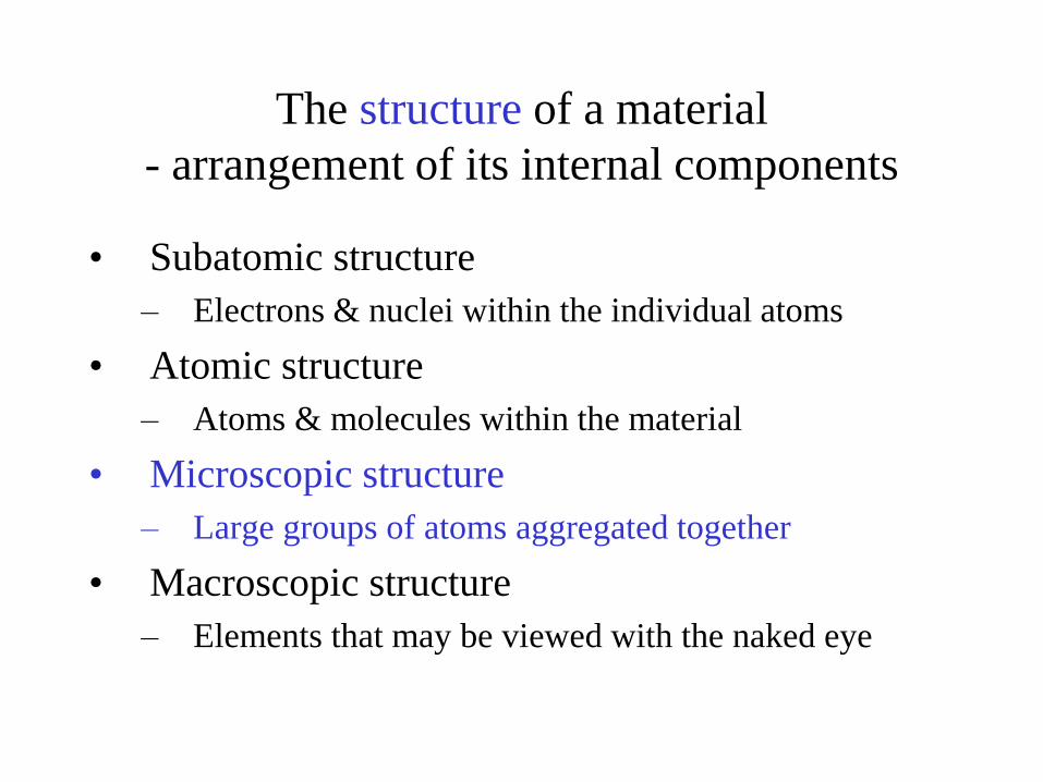
The structure of a material
- arrangement of its internal components
• Subatomic structure
– Electrons & nuclei within the individual atoms
• Atomic structure
– Atoms & molecules within the material
• Microscopic structure
– Large groups of atoms aggregated together
• Macroscopic structure
– Elements that may be viewed with the naked eye
3.2 Fundamental Concepts
• Crystalline materials
– Atoms are situated in a repeating or periodic array over
large atomic distances
– Long-range order
• Non-crystalline materials (amorphous materials)
– Do not have long-range order
– May have short-range order
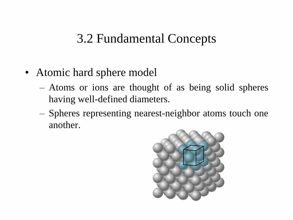
3.2 Fundamental Concepts
• Atomic hard sphere model
– Atoms or ions are thought of as being solid spheres
having well-defined diameters.
– Spheres representing nearest-neighbor atoms touch one
another.
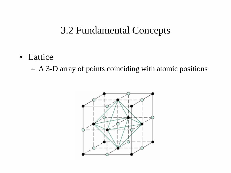
3.2 Fundamental Concepts
• Lattice
– A 3-D array of points coinciding with atomic positions
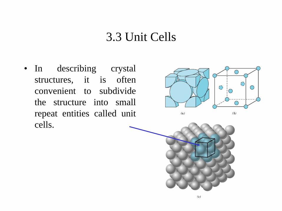
3.3 Unit Cells
• In describing crystal
structures, it is often
convenient to subdivide
the structure into small
repeat entities called unit
cells.
• Atomic bonding is metallic
Directional or non-directional?
Would number of nearest neighbor atoms be large or
small then?
How about density of atomic packing? Large or
small?
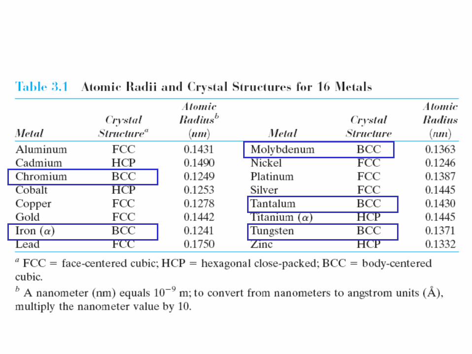
3.4 Metallic Crystal Structures
3.4 Metallic Crystal Structures
• Crystal structures of common metals
– Face-centered cubic crystal structure
– Body-centered cubic crystal structures
– Hexagonal close-packed crystal structure
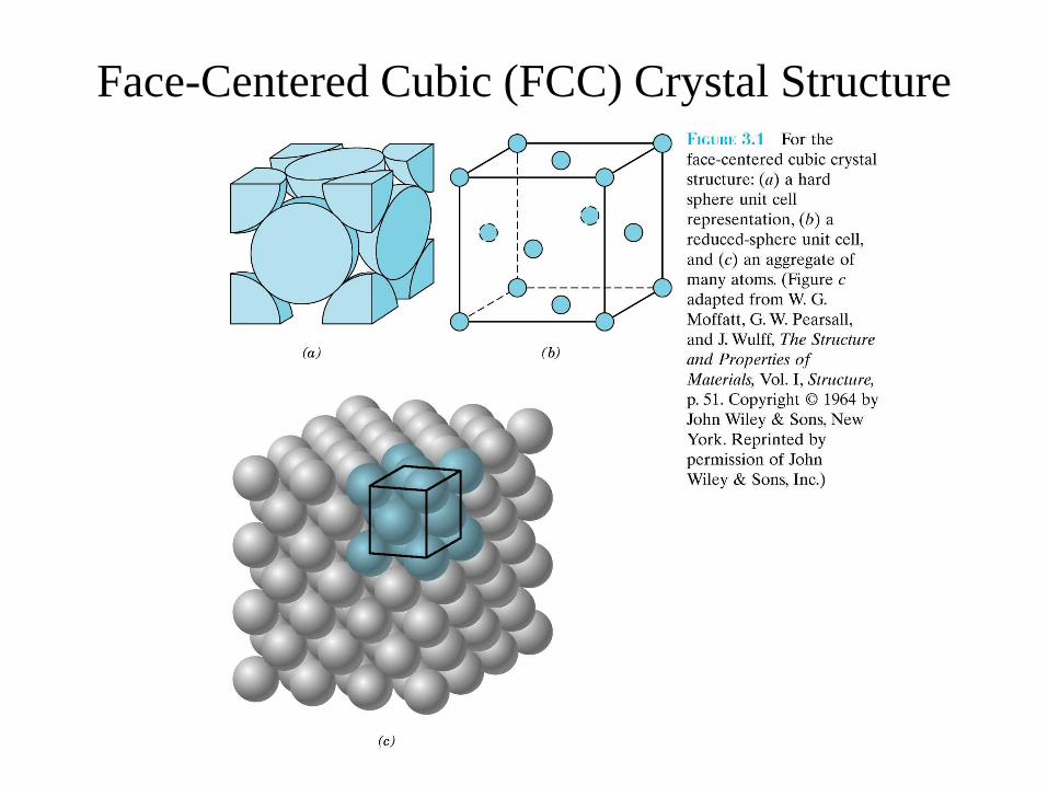
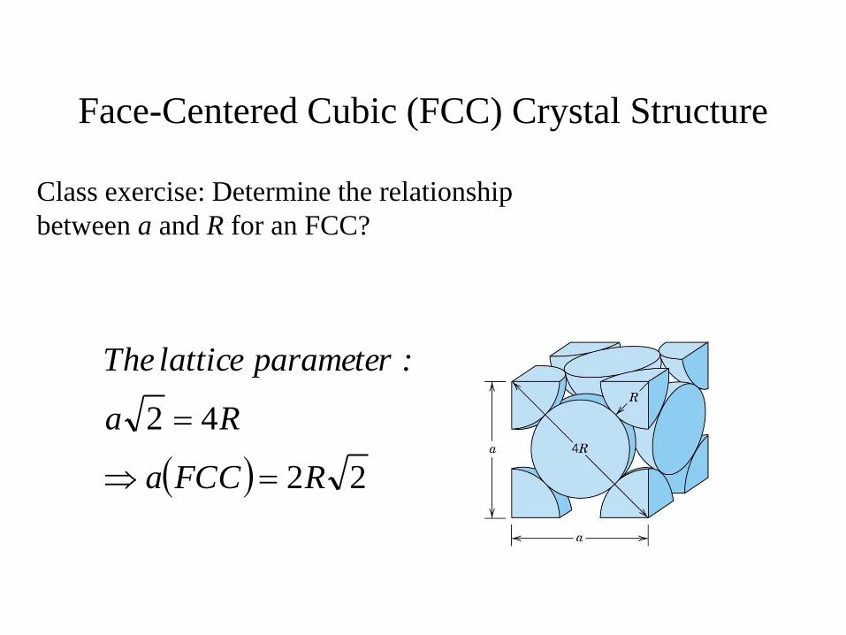
Face-Centered Cubic (FCC) Crystal Structure
Face-Centered Cubic (FCC) Crystal Structure
22
42
RFCCa
Ra
:parameter lattice The
Class exercise: Determine the relationship
between a and R for an FCC?
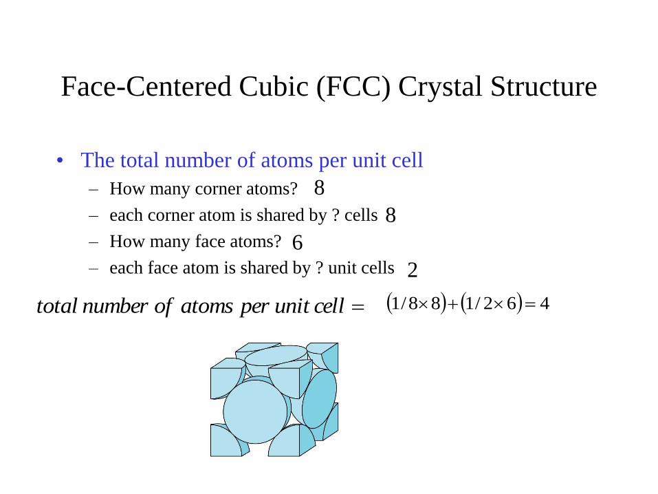
Face-Centered Cubic (FCC) Crystal Structure
• The total number of atoms per unit cell
– How many corner atoms?
– each corner atom is shared by ? cells
– How many face atoms?
– each face atom is shared by ? unit cells
462/188/1
8
8
6
2
cell unit per atoms of number total
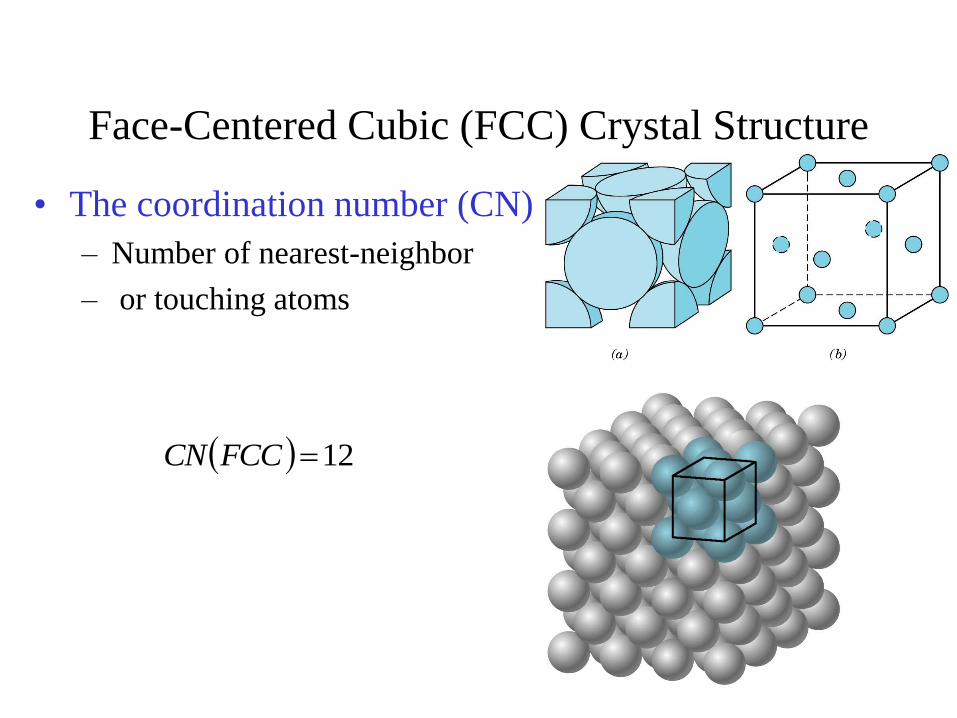
Face-Centered Cubic (FCC) Crystal Structure
• The coordination number (CN)
– Number of nearest-neighbor
– or touching atoms
12FCCCN
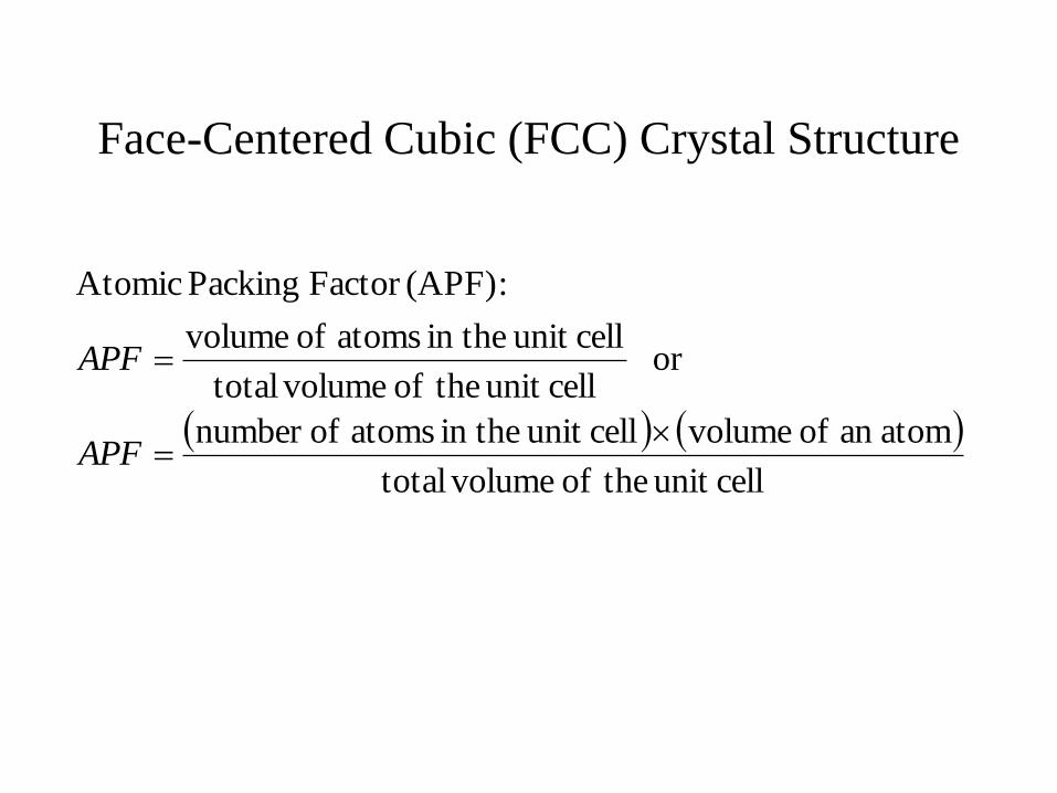
Face-Centered Cubic (FCC) Crystal Structure
cellunit theof volumetotal
atoman of volumecellunit in the atoms ofnumber
or cellunit theof volumetotal
cellunit in the atoms of volume
:(APF)Factor Packing Atomic
APF
APF
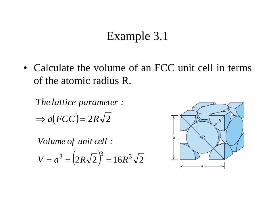
Example 3.1
• Calculate the volume of an FCC unit cell in terms
of the atomic radius R.
22RFCCa
:parameter lattice The
21622 333 RRaV
:cell unit of Volume
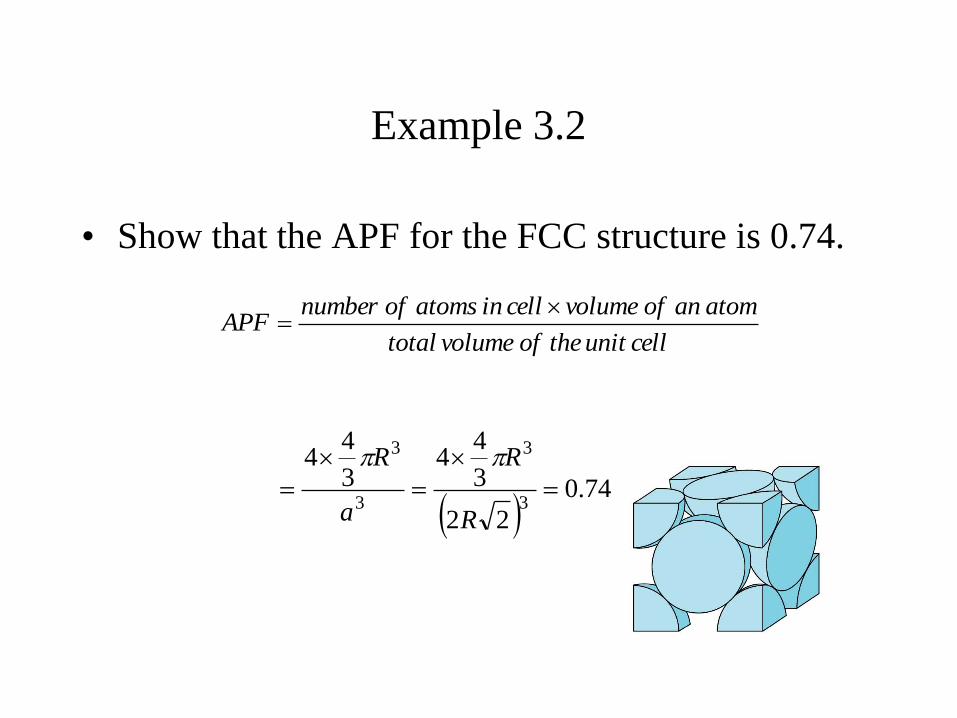
Example 3.2
• Show that the APF for the FCC structure is 0.74.
74.0
22
3
44
3
44
3
3
3
3
R
R
a
R
cell unit the of volume total
atom an of volume cell in atoms of numberAPF
Face-Centered Cubic (FCC) Crystal Structure
• CN of 12
– Maximum possible for spheres with same diameter.
• APF of 0.74
– maximum possible for spheres with same diameter.
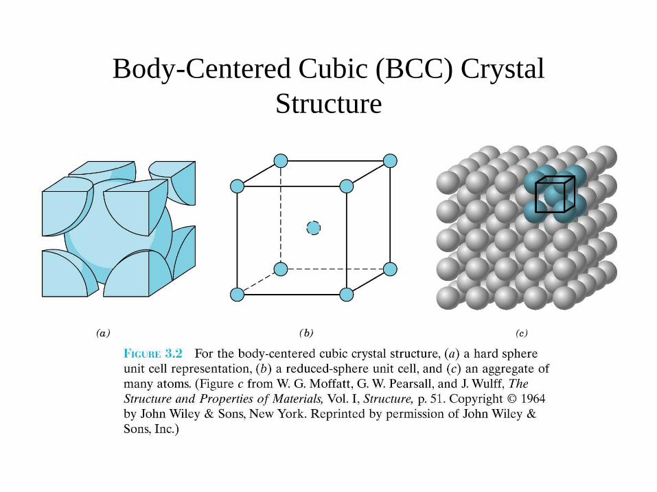
Body-Centered Cubic (BCC) Crystal
Structure
Body-Centered Cubic (BCC) Crystal
Structure
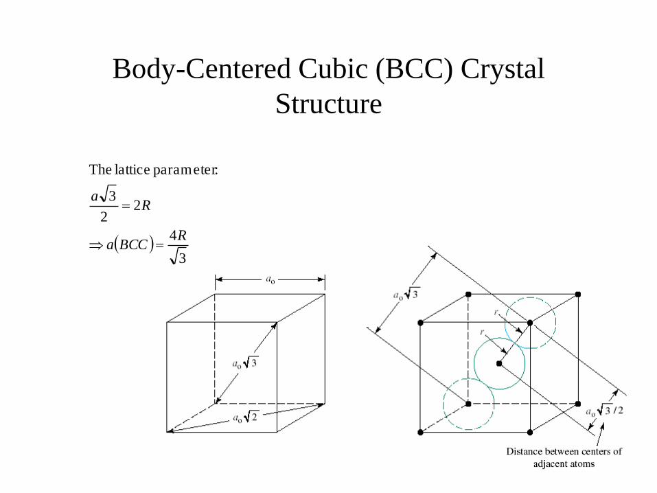
3
4
22
3
:parameter lattice The
RBCCa
Ra
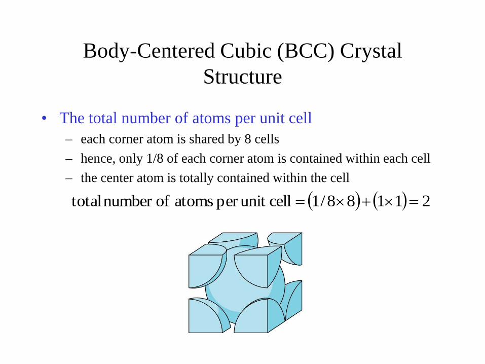
Body-Centered Cubic (BCC) Crystal
Structure
• The total number of atoms per unit cell
– each corner atom is shared by 8 cells
– hence, only 1/8 of each corner atom is contained within each cell
– the center atom is totally contained within the cell
21188/1cellunit per atoms ofnumber total
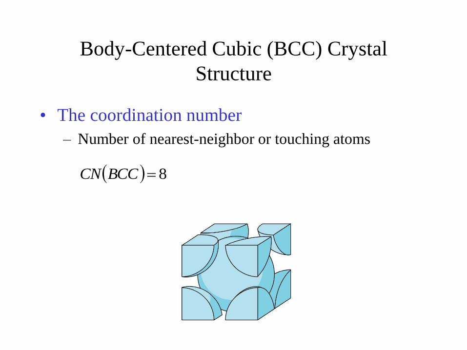
Body-Centered Cubic (BCC) Crystal
Structure
• The coordination number
– Number of nearest-neighbor or touching atoms
8BCCCN
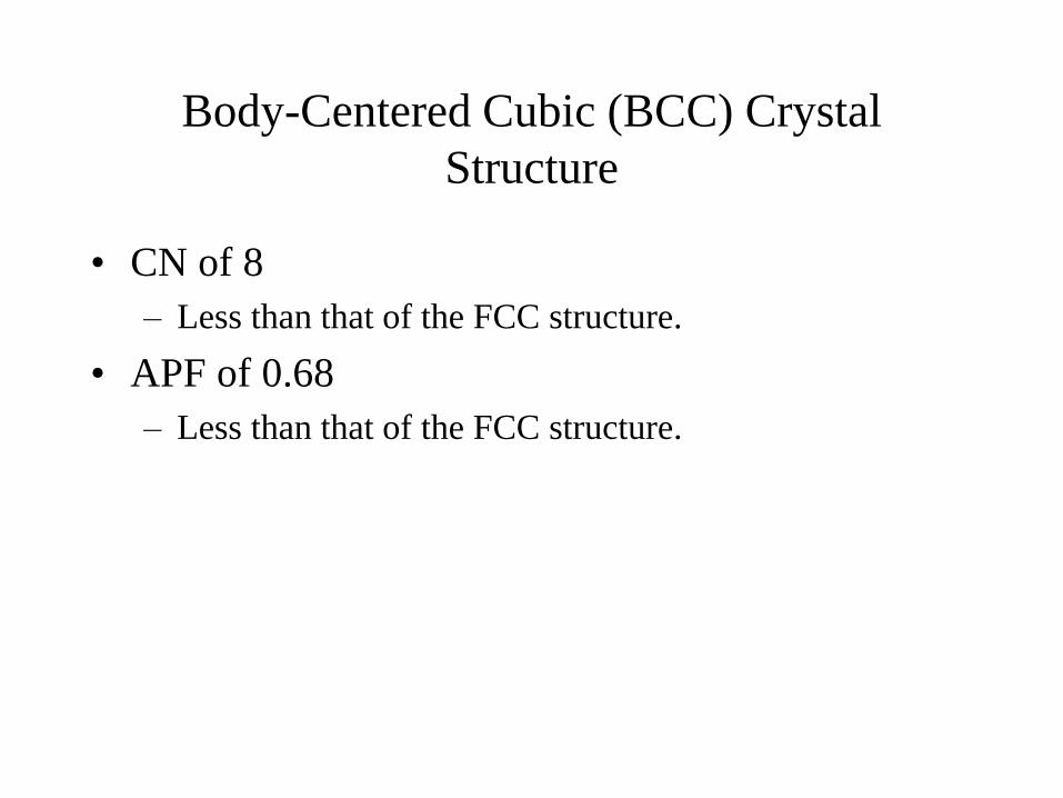
Body-Centered Cubic (BCC) Crystal
Structure
• CN of 8
– Less than that of the FCC structure.
• APF of 0.68
– Less than that of the FCC structure.
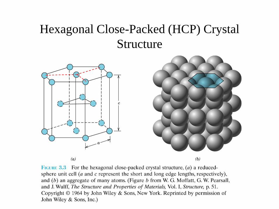
Hexagonal Close-Packed (HCP) Crystal
Structure
Hexagonal Close-Packed (HCP) Crystal
Structure
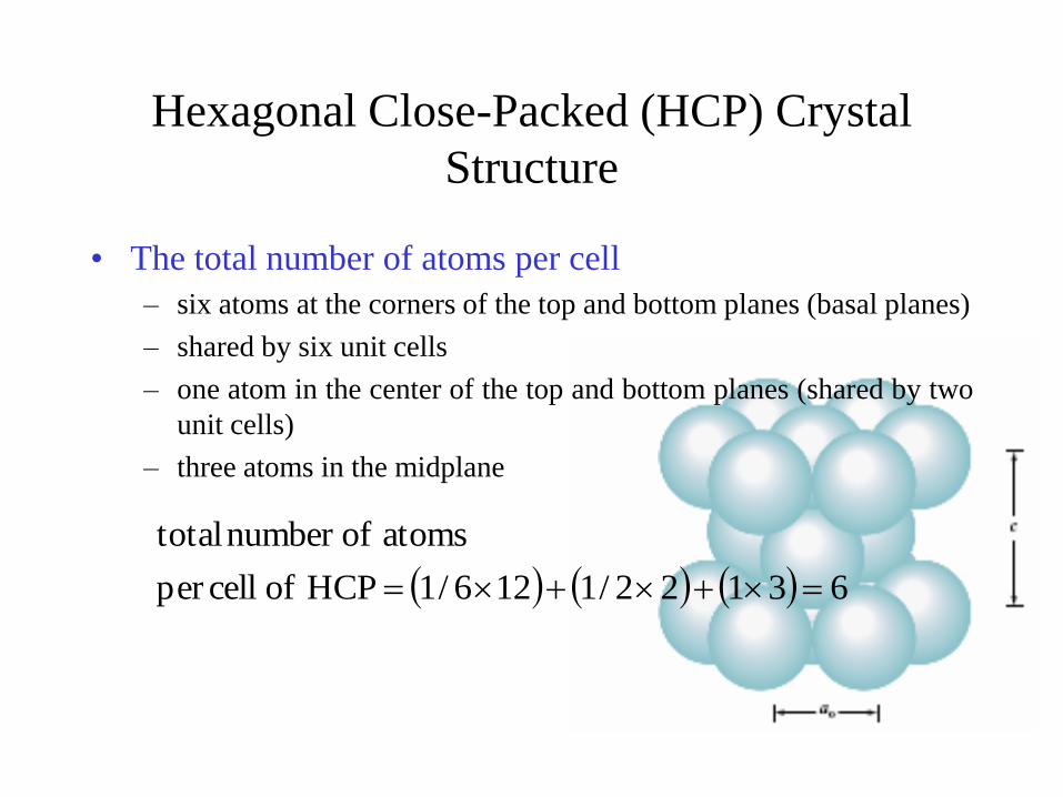
• The total number of atoms per cell
– six atoms at the corners of the top and bottom planes (basal planes)
– shared by six unit cells
– one atom in the center of the top and bottom planes (shared by two
unit cells)
– three atoms in the midplane
63122/1126/1HCP of cellper
atoms ofnumber total
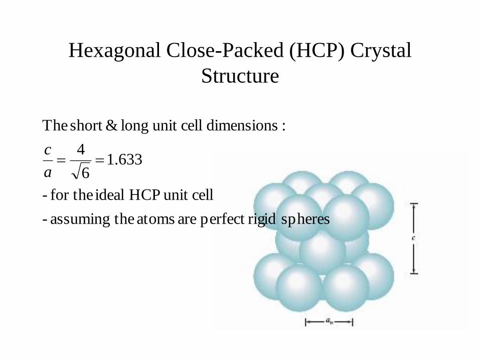
Hexagonal Close-Packed (HCP) Crystal
Structure
spheres rigidperfect are atoms theassuming -
cellunit HCP ideal for the -
633.16
4
:dimensions cellunit long &short The
a
c
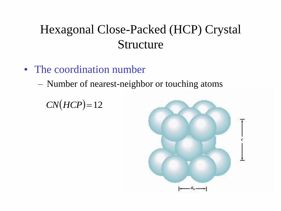
Hexagonal Close-Packed (HCP) Crystal
Structure
• The coordination number
– Number of nearest-neighbor or touching atoms
12HCPCN
Hexagonal Close-Packed (HCP) Crystal
Structure
• CN of 12
– Maximum possible for spheres with same diameter.
• APF of 0.74
– maximum possible for spheres with same diameter.
3.5 Density Computations
• A knowledge of the crystal structure of a metallic
solid permits computation of its theoretical
density:
number. sAvogadro' theis
and cellunit theof volume theis
weight,atomic theis
cell,unit each in atoms ofnumber theis where
A
C
AC
N
V
A
n
NV
nA

Example 3.4
• Copper has an atomic radius of 0.128 nm, an FCC
crystal structure and an atomic weight of 63.5
g/mol. Compute its theoretical density and
compare with its measured density.
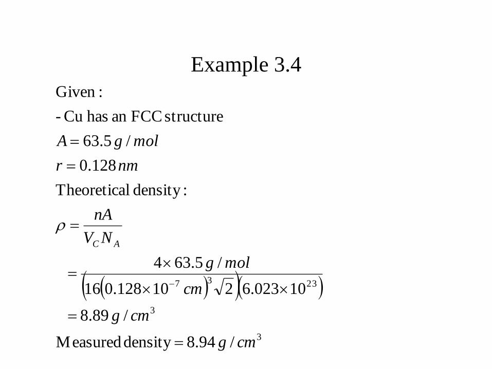
Example 3.4
/94.8density Measured
/89.8
10023.6210128.016
/5.634
:density lTheoretica
128.0
/5.63
structure FCCan hasCu -
:Given
3
3
2337
cmg
cmg
cm
molg
NV
nA
nmr
molgA
AC
3.6 Polymorphism and Allotropy
• Polymorphism
– Some metals/non-metals have more than one crystal
structure
• Allotropy
– Elemental solids with more than one crystal structure
– Carbon as graphite or diamond
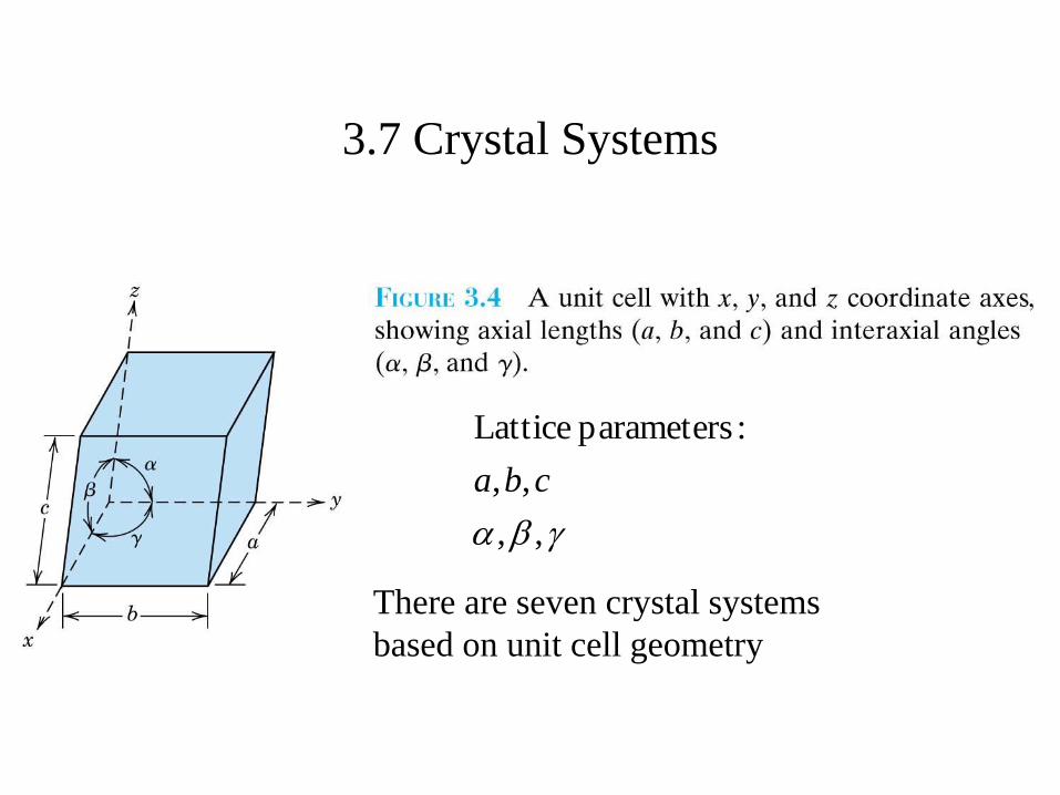
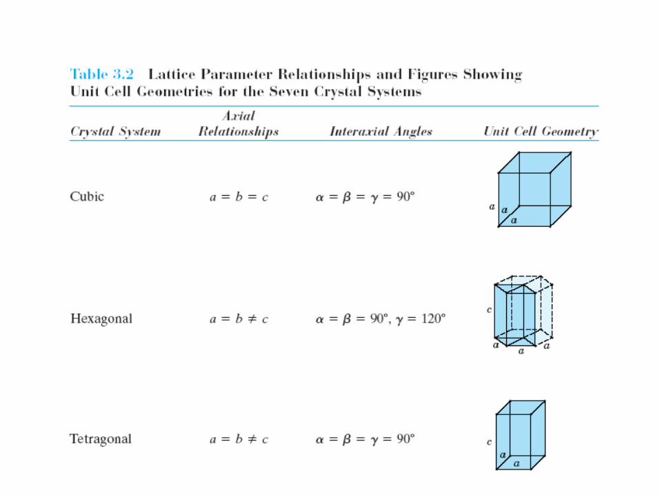
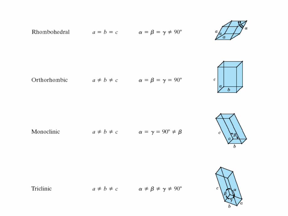
3.7 Crystal Systems
,,
,,
:parameters Lattice
cba
There are seven crystal systems
based on unit cell geometry
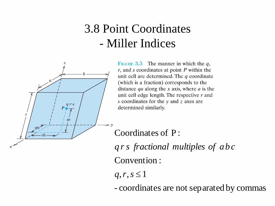
3.8 Point Coordinates
- Miller Indices
commasby separatednot are scoordinate -
1,,
:Convention
:P of sCoordinate
srq
cbaofmultiplesfractionalsrq
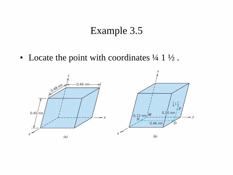
Example 3.5
• Locate the point with coordinates ¼ 1 ½ .
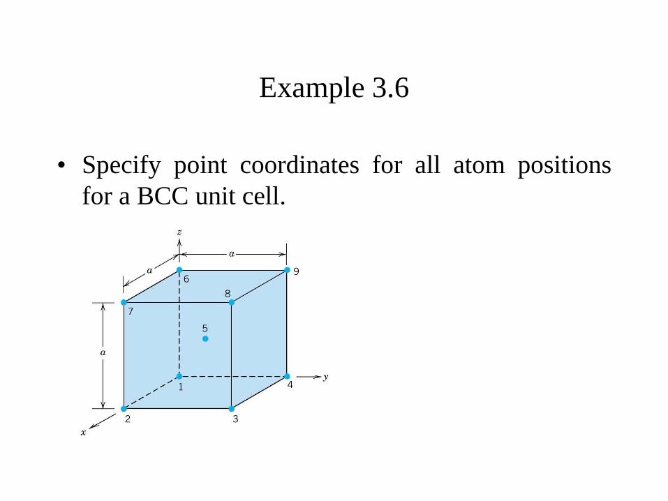
Example 3.6
• Specify point coordinates for all atom positions
for a BCC unit cell.
3.9 Crystallographic Directions
A vector of convenient length is positioned such that it passes through the origin of the coordinate system. Any vector may be translated throughout the crystal lattice without alteration, if parallelism is
maintained.
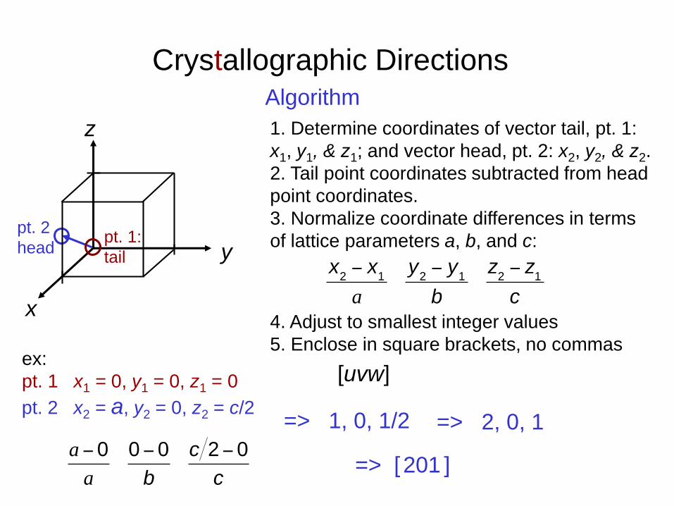
Crystallographic Directions
1. Determine coordinates of vector tail, pt. 1:
x1, y1, & z1; and vector head, pt. 2: x2, y2, & z2.
2. Tail point coordinates subtracted from head
point coordinates.
3. Normalize coordinate differences in terms
of lattice parameters a, b, and c:
4. Adjust to smallest integer values
5. Enclose in square brackets, no commas
[uvw]ex:
pt. 1 x1 = 0, y1 = 0, z1 = 0
=> 1, 0, 1/2
=> [201 ]
z
x
Algorithm
y
=> 2, 0, 1
pt. 2
headpt. 1:
tail
pt. 2 x2 = a, y2 = 0, z2 = c/2
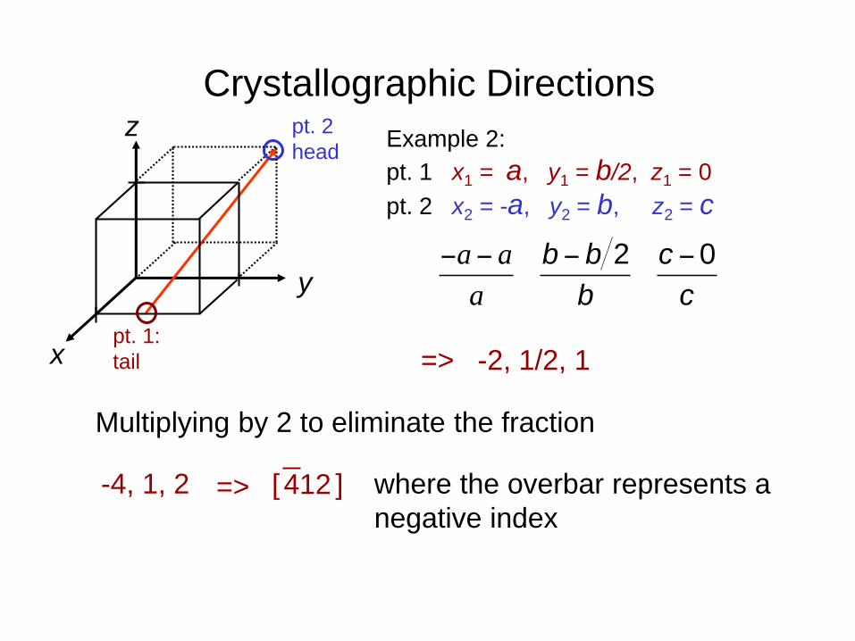
Crystallographic Directions
-4, 1, 2
z
x
where the overbar represents a
negative index
[ 412 ]=>
y
Example 2:
pt. 1 x1 = a, y1 = b/2, z1 = 0
pt. 2 x2 = -a, y2 = b, z2 = c
=> -2, 1/2, 1
pt. 2
head
pt. 1:
tail
Multiplying by 2 to eliminate the fraction
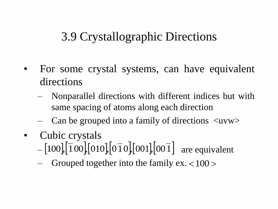
3.9 Crystallographic Directions
• For some crystal systems, can have equivalent
directions
– Nonparallel directions with different indices but with
same spacing of atoms along each direction
– Can be grouped into a family of directions <uvw>
• Cubic crystals
– are equivalent
– Grouped together into the family ex.
100,001,010,010,001,100
100
Learning Outcomes met thus far!
1. Describe difference in atomic/molecular structure
between crystalline/non-crystalline
2. Draw unit cells for FCC, BCC, HCP
3. Derive the relationship between unit cell edge
length and atomic radius for FCC, BCC
4. Compute the densities for metals having FCC,
BCC given unit cell dimensions
5. Sketch crystallographic directions within unit
cells

HCP Crystallographic Directions
• Hexagonal Crystals
– 4 parameter Miller-Bravais lattice coordinates are
related to the direction indices (i.e., uvw) in the ‘3
space’ Bravais lattice as follows.
Ww
t
v
u
)vu( +-
)UV2(3
1-
)VU2(3
1-
]uvtw[]WVU[
-a3
a1
a2
z
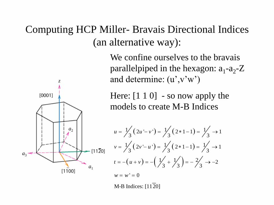
Computing HCP Miller- Bravais Directional Indices
(an alternative way):
-a3
a1
a2
z
We confine ourselves to the bravais
parallelpiped in the hexagon: a1-a2-Z
and determine: (u’,v’w’)
Here: [1 1 0] - so now apply the
models to create M-B Indices
1 1 12 ' ' 2 1 1 13 3 3
1 1 12 ' ' 2 1 1 13 3 3
1 1 2 23 3 3
' 0
M-B Indices: [1120]
u u v
v v u
t u v
w w
48
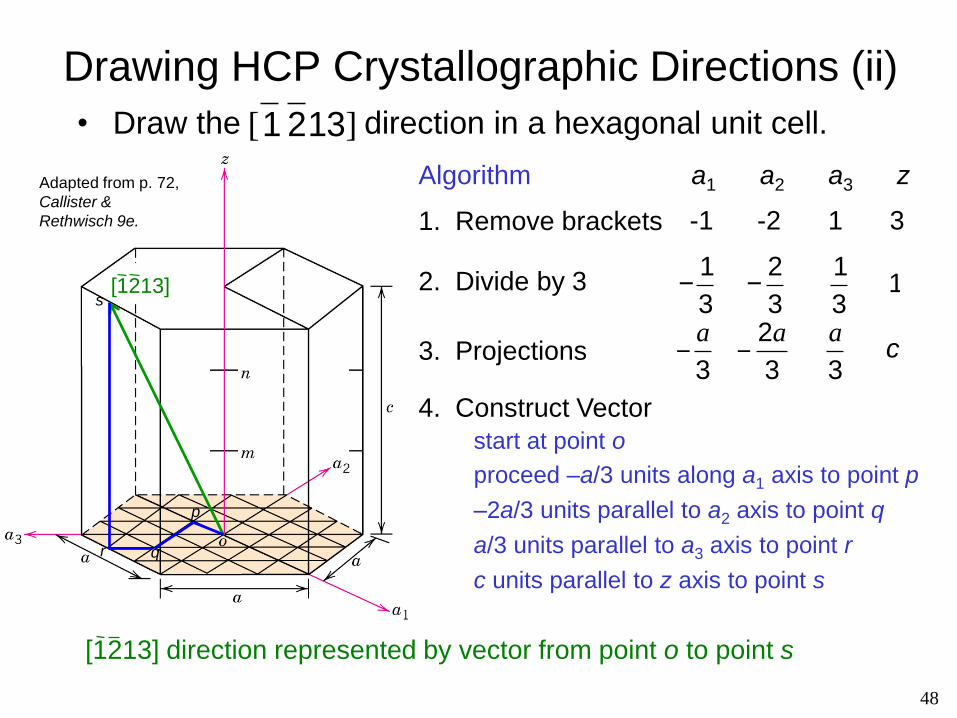
Drawing HCP Crystallographic Directions (ii)
• Draw the direction in a hexagonal unit cell.
[1213]
4. Construct Vector
1. Remove brackets -1 -2 1 3
Algorithm a1 a2 a3 z
2. Divide by 3
-1
3 -
2
3
1
3 1
3. Projections
proceed –a/3 units along a1 axis to point p
–2a/3 units parallel to a2 axis to point q
a/3 units parallel to a3 axis to point r
c units parallel to z axis to point s
[1 2 13]
p
qr
s
start at point o
Adapted from p. 72,
Callister &
Rethwisch 9e.
[1213] direction represented by vector from point o to point s
3.10 Crystallographic Planes
1. If the plane passes through the selected origin, anotherparallel plane must be constructed by translationwithin the unit cell to another corner.
2. The length of the planar intercept for each axis isdetermined in terms of the lattice parameters a, b and c.
3. The reciprocals of the above numbers are taken. A planethat parallels an axis is considered to have an infiniteintercept.
4. The numbers are changed to the set of smallest integersby multiplication or division by a common factor.
5. The integer indices, not separated by commas, areenclosed within parentheses:
lkh
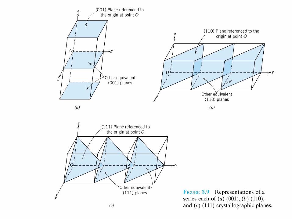
3.10 Crystallographic Planes
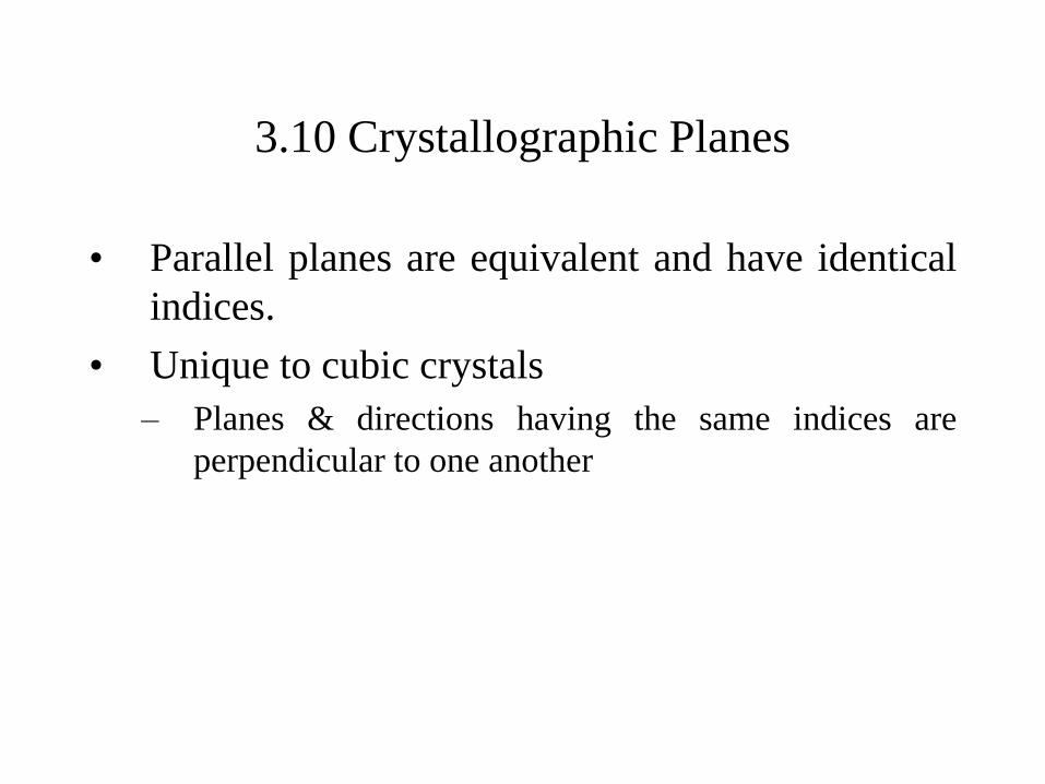
• Parallel planes are equivalent and have identical
indices.
• Unique to cubic crystals
– Planes & directions having the same indices are
perpendicular to one another
Crystallographic Planesz
x
ya b
c
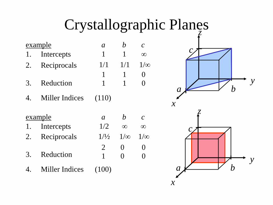
4. Miller Indices (110)
example a b cz
x
ya b
c
4. Miller Indices (100)
1. Intercepts 1 1
2. Reciprocals 1/1 1/1 1/
1 1 03. Reduction 1 1 0
1. Intercepts 1/2
2. Reciprocals 1/½ 1/ 1/
2 0 03. Reduction 1 0 0
example a b c
Crystallographic Planes
z
x
ya b
c
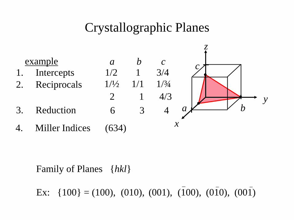
4. Miller Indices (634)
example
1. Intercepts 1/2 1 3/4a b c
2. Reciprocals 1/½ 1/1 1/¾
2 1 4/3
3. Reduction 6 3 4
(001)(010),
Family of Planes {hkl}
(100), (010),(001),Ex: {100} = (100),
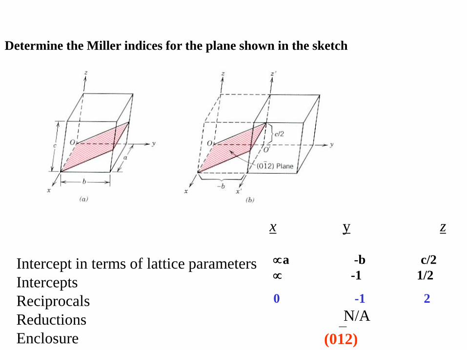
x y z
Intercept in terms of lattice parameters
Intercepts
Reciprocals
Reductions
Enclosure
a -b c/2
-1 1/2
0 -1 2
N/A
(012)
Determine the Miller indices for the plane shown in the sketch
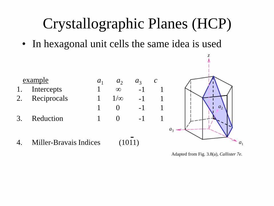
Crystallographic Planes (HCP)
• In hexagonal unit cells the same idea is used
example a1 a2 a3 c
4. Miller-Bravais Indices (1011)
1. Intercepts 1 -1 1
2. Reciprocals 1 1/
1 0
-1
-1
1
1
3. Reduction 1 0 -1 1
a2
a3
a1
z
Adapted from Fig. 3.8(a), Callister 7e.
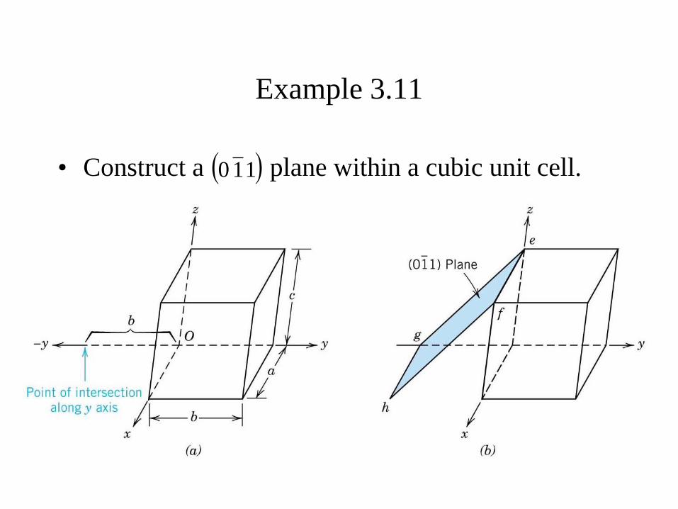
Example 3.11
• Construct a plane within a cubic unit cell. 110
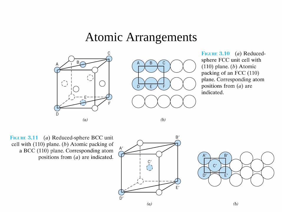
Atomic Arrangements
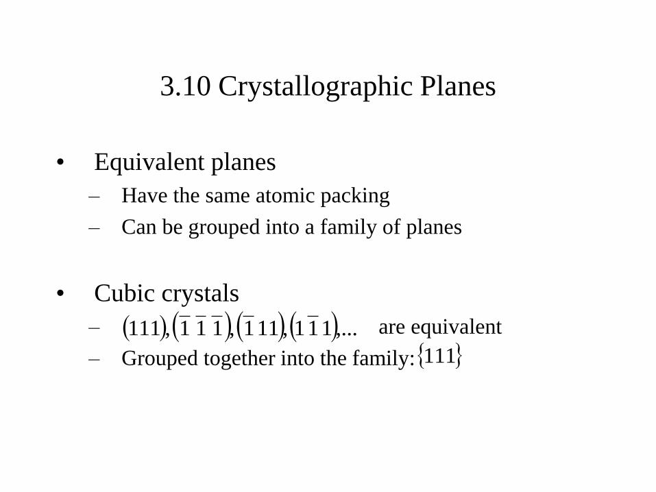
3.10 Crystallographic Planes
• Equivalent planes
– Have the same atomic packing
– Can be grouped into a family of planes
• Cubic crystals
– are equivalent
– Grouped together into the family:
,...111,111,111,111
111
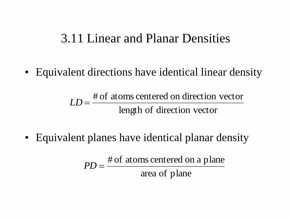
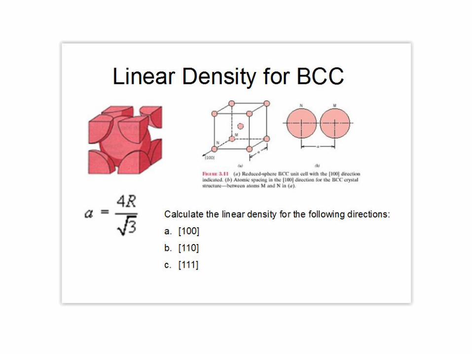
3.11 Linear and Planar Densities
• Equivalent directions have identical linear density
• Equivalent planes have identical planar density
vectordirection oflength
vectordirection on centered atoms of #LD
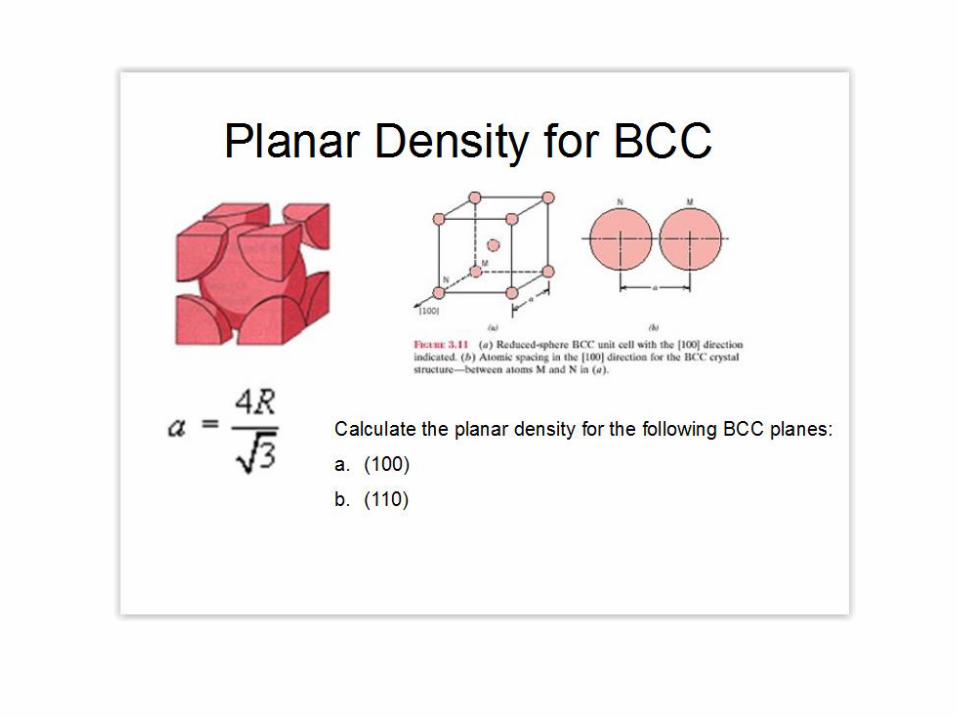
plane of area
plane aon centered atoms of #PD
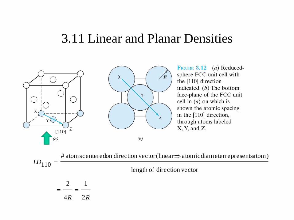
3.11 Linear and Planar Densities
RR
LD
2
1
4
2
vectordirection oflength
atom) representsdiameter atomic (linear vector direction on centered atoms#
110
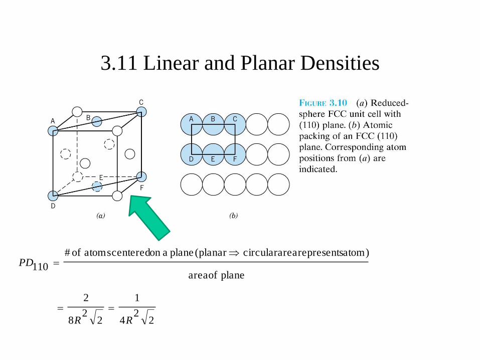
3.11 Linear and Planar Densities
22
4
1
22
8
2
plane of area
atom) represents areacircular (planar plane aon centered atoms of #
110
RR
PD
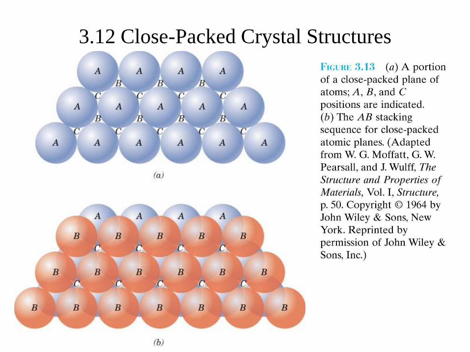
3.12 Close-Packed Crystal Structure
• Close-packed directions
– Directions with maximum atom-packing density
• Close-packed planes
– Planes with maximum atom-packing density
• Atoms packed together are close-packed if they occupy the
minimum volume possible (assuming they are
incompressible spheres). They would have the maximum
possible packing efficiency, defined as the ratio of volume
of atoms to volume of space used.
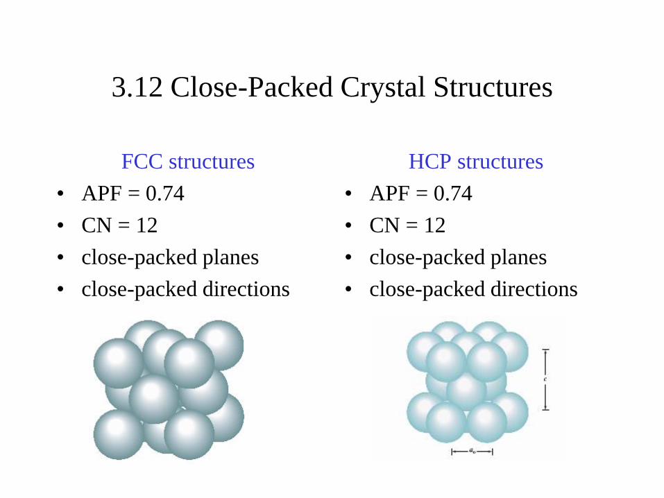
3.12 Close-Packed Crystal Structures
FCC structures
• APF = 0.74
• CN = 12
• close-packed planes
• close-packed directions
HCP structures
• APF = 0.74
• CN = 12
• close-packed planes
• close-packed directions

3.12 Close-Packed Crystal Structures
3.12 Close-Packed Crystal Structures
Centers of this layer are
directly above the bottom A layer
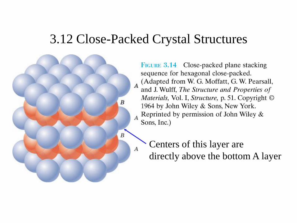
3.12 Close-Packed Crystal Structures
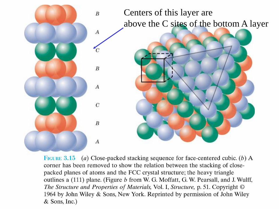
Centers of this layer are
above the C sites of the bottom A layer
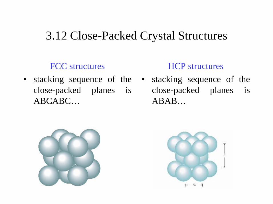
3.12 Close-Packed Crystal Structures
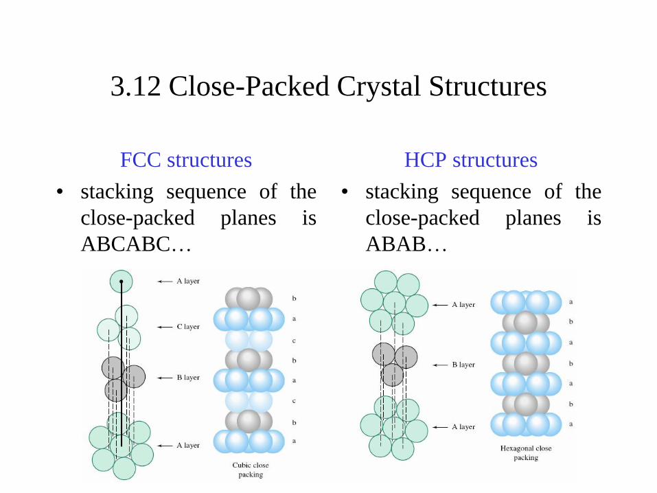
FCC structures
• stacking sequence of the
close-packed planes is
ABCABC…
HCP structures
• stacking sequence of the
close-packed planes is
ABAB…
3.12 Close-Packed Crystal Structures
FCC structures
• stacking sequence of the
close-packed planes is
ABCABC…
HCP structures
• stacking sequence of the
close-packed planes is
ABAB…
3.13 Single Crystals
• Single crystal
– the periodic & repeated arrangement of atoms is perfect
or extends throughout the material without interruption.
– Silicon single crystals in the semiconductor industry.
3.14 Polycrystalline Materials
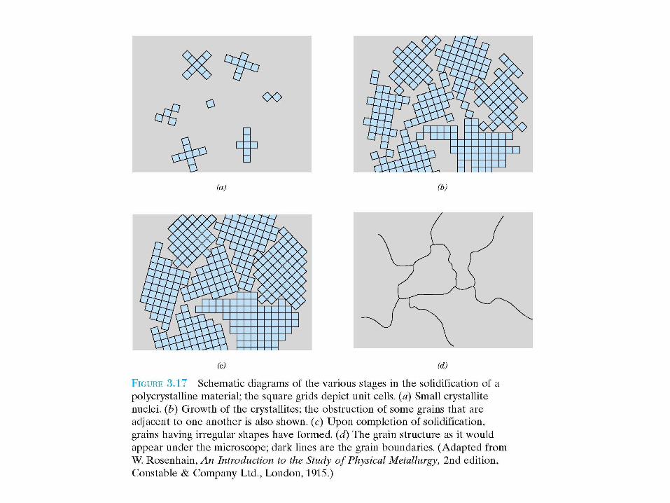
• Polycrystalline
– Composed of a collection of many crystals or grains
3.15 Anisotropy
• Anisotropy
– Materials having different properties in different
directions
• Isotropy
– Materials having same properties in all directions.
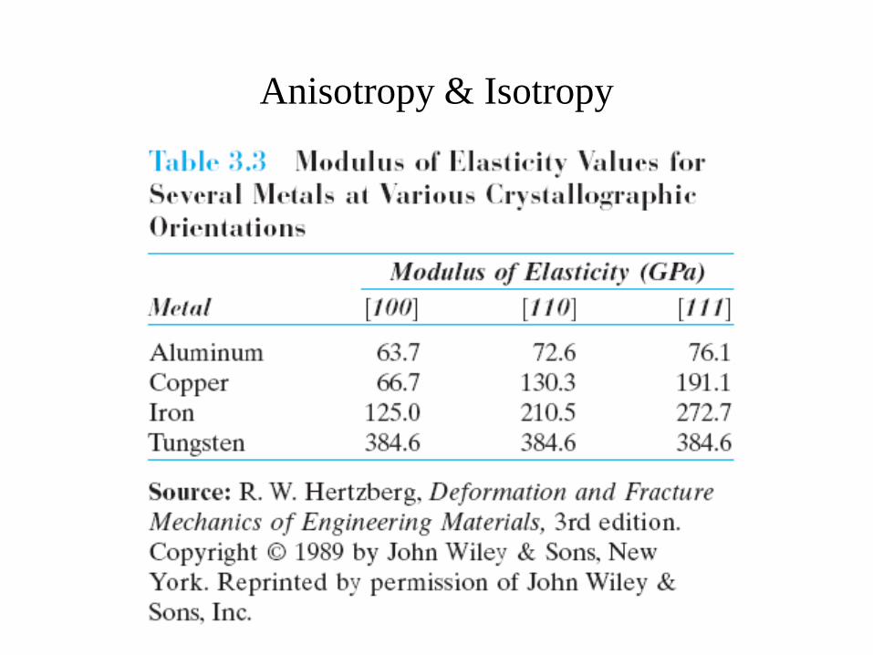
Anisotropy & Isotropy
3.17 Non-crystalline Solids
• Non-crystalline materials (amorphous materials)
– Do not have long-range order
– May have short-range order
• Rapid cooling through the freezing temperature
favors formation of a non-crystalline solid
– Little time is allowed for the ordering process
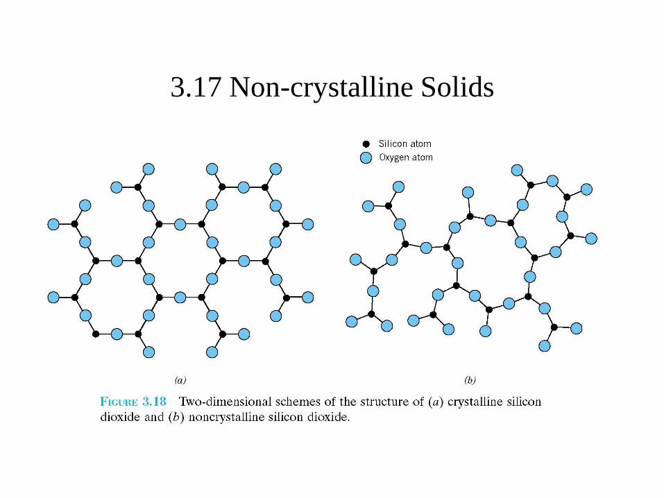
3.17 Non-crystalline Solids
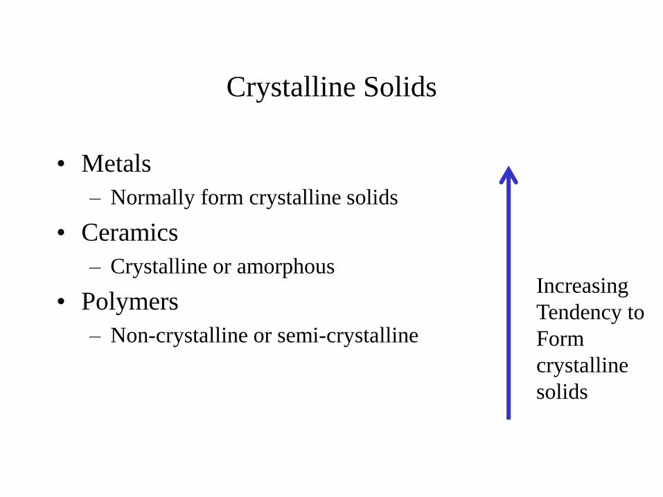
Crystalline Solids
• Metals
– Normally form crystalline solids
• Ceramics
– Crystalline or amorphous
• Polymers
– Non-crystalline or semi-crystalline
Increasing
Tendency to
Form
crystalline
solids


![Mechanisms - Georgia Southern University-Armstrong …engineering.armstrong.edu/cameron/Mechanisms[1].pdf · internally combustible engine; two slider crank mechanisms in the form](https://img.pdfslide.us/doc/110x75/5ab486707f8b9a7c5b8bdcb0/mechanisms-georgia-southern-university-armstrong-1pdfinternally-combustible.jpg)