Embed Size (px)
Citation preview
GE Medical SystemsWe bring good things to life.
Introduction toCardiovascular MR Imaging
A P r a c t i c a l G u i d e t o C a r d i o v a s c u l a r M R I
The author would like to thank the numerouspeople who aided in the development and ultimate creation of this applications/usersguide. Their help, patience, and guidance were crucial in answering many questions and providing suggestions and comments.
Specific Thanks to:
Patricia G. Bischoff, RT (R)(N)Karen E. Bove-Bettis, RT (R)(MR)Bob Day, RT (MR)(CT)Fred Epstein, Ph.D.Thomas K. F. Foo, Ph.D.Sudha Maniam, M.S.Tom McMahonMarcela Montequin RT (M)(MR)Steven D. Wolff, M.D., Ph.D.Mary Zimmerman
The following Cardiac Development ProgramSites graciously provided images and assisted in cardiac protocol development:
Integrated Cardiovascular Therapeutics (ICT),Woodbury, NY.
Laboratory of Cardiac Energetics, National Heart, Lung, and Blood Institute,National Institutes of Health, Bethesda, MD.
Michigan State University,Department of Radiology,East Lansing, MI.
Acknowledgments
ii
1
GE Medical Systems
Introduction to Cardiovascular MR ImagingA Practical Guide to Cardiovascular MRI
By Cindy R. Comeau, B.S., RT (N)(MR)
Cardiovascular MRI Senior Advanced Applications Specialist
GE Medical SystemsMilwaukee, Wisconsin
© 1999 General Electric Company
PrefaceThis work is a practical guide to understanding and using cardiovascular MRI as an imaging modality. Use it to familiarize yourself with the system’scapabilities, flexibility and diagnostic quality. You’ll be impressed.
2
What’s Inside
Acknowledgments . . . . . . . . . . . . . . . . . . . . . . . . . . . . . . . . . . . . . . . . . . . . . . . . . . . . . . . . . . . . . . . . . ii
Signa® CV/i ™ Introduction . . . . . . . . . . . . . . . . . . . . . . . . . . . . . . . . . . . . . . . . . . . . . . . . . . . . . . . . . 3
Cardiovascular MR Imaging Techniques . . . . . . . . . . . . . . . . . . . . . . . . . . . . . . . . . . . . . . . . 4
Black Blood Techniques . . . . . . . . . . . . . . . . . . . . . . . . . . . . . . . . . . . . . . . . . . . . . . . . . . . . . 5
White Blood Techniques . . . . . . . . . . . . . . . . . . . . . . . . . . . . . . . . . . . . . . . . . . . . . . . . . . . . . 6
Cardiac Structure and Function . . . . . . . . . . . . . . . . . . . . . . . . . . . . . . . . . . . . . . . . . . . . . . . . . . 9
Cardiac Anatomy . . . . . . . . . . . . . . . . . . . . . . . . . . . . . . . . . . . . . . . . . . . . . . . . . . . . . . . . . . . 9
Cardiac Circulation . . . . . . . . . . . . . . . . . . . . . . . . . . . . . . . . . . . . . . . . . . . . . . . . . . . . . . . . 10
Coronary Arterial Blood Supply . . . . . . . . . . . . . . . . . . . . . . . . . . . . . . . . . . . . . . . . . . . . . . 11
Electrocardiography . . . . . . . . . . . . . . . . . . . . . . . . . . . . . . . . . . . . . . . . . . . . . . . . . . . . . . . 13
Scan Setup . . . . . . . . . . . . . . . . . . . . . . . . . . . . . . . . . . . . . . . . . . . . . . . . . . . . . . . . . . . . . . . . . . . . . . . . . 15
Gating Checklist . . . . . . . . . . . . . . . . . . . . . . . . . . . . . . . . . . . . . . . . . . . . . . . . . . . . . . . . . . 15
Positioning the Electrodes . . . . . . . . . . . . . . . . . . . . . . . . . . . . . . . . . . . . . . . . . . . . . . . . . . . 16
Imaging Plane Selection . . . . . . . . . . . . . . . . . . . . . . . . . . . . . . . . . . . . . . . . . . . . . . . . . . . . . . . . . . 18
Sagittal Localizer . . . . . . . . . . . . . . . . . . . . . . . . . . . . . . . . . . . . . . . . . . . . . . . . . . . . . . . . . . 18
Long-Axis Localizer . . . . . . . . . . . . . . . . . . . . . . . . . . . . . . . . . . . . . . . . . . . . . . . . . . . . . . . . 20
Short-Axis Plane . . . . . . . . . . . . . . . . . . . . . . . . . . . . . . . . . . . . . . . . . . . . . . . . . . . . . . . . . . 22
Radial Views . . . . . . . . . . . . . . . . . . . . . . . . . . . . . . . . . . . . . . . . . . . . . . . . . . . . . . . . . . . . . . 24
Coronal Ascending Aorta Plane . . . . . . . . . . . . . . . . . . . . . . . . . . . . . . . . . . . . . . . . . . . . . . 26
Orthogonal Imaging Planes . . . . . . . . . . . . . . . . . . . . . . . . . . . . . . . . . . . . . . . . . . . . . . . . . 28
Glossary of Terms . . . . . . . . . . . . . . . . . . . . . . . . . . . . . . . . . . . . . . . . . . . . . . . . . . . . . . . . . . . . . . . . . 31
Measurements of Ventricular Function . . . . . . . . . . . . . . . . . . . . . . . . . . . . . . . . . . . . . . . . . 36
Acronyms . . . . . . . . . . . . . . . . . . . . . . . . . . . . . . . . . . . . . . . . . . . . . . . . . . . . . . . . . . . . . . . . . . . . . . . . . . 36
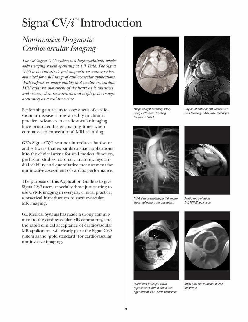
Noninvasive Diagnostic Cardiovascular ImagingThe GE Signa CV/i system is a high-resolution, wholebody imaging system operating at 1.5 Tesla. The SignaCV/i is the industry’s first magnetic resonance systemoptimized for a full range of cardiovascular applications.With impressive image quality and resolution, cardiacMRI captures movement of the heart as it contracts and relaxes, then reconstructs and displays the imagesaccurately as a real-time cine.
Performing an accurate assessment of cardio-vascular disease is now a reality in clinicalpractice. Advances in cardiovascular imaginghave produced faster imaging times whencompared to conventional MRI scanning.
GE’s Signa CV/i scanner introduces hardwareand software that expands cardiac applicationsinto the clinical arena for wall motion, function,perfusion studies, coronary anatomy, myocar-dial viability and quantitative measurement fornoninvasive assessment of cardiac performance.
The purpose of this Application Guide is to giveSigna CV/i users, especially those just starting touse CVMR imaging in everyday clinical practice,a practical introduction to cardiovascular MR imaging.
GE Medical Systems has made a strong commit-ment to the cardiovascular MR community, andthe rapid clinical acceptance of cardiovascularMR applications will clearly place the Signa CV/isystem as the “gold standard” for cardiovascularnoninvasive imaging.
3
Region of anterior left ventricularwall thinning. FASTCINE technique.
MRA demonstrating partial anom-alous pulmonary venous return.
Aortic regurgitation. FASTCINE technique.
Mitral and tricuspid valve replacement with a clot in theright atrium. FASTCINE technique.
Short Axis plane Double-IR FSEtechnique.
Image of right coronary arteryusing a 2D vessel tracking technique (WIP).
Signa® CV/i ™ Introduction
The Signa CV/i supports a broad array of pulsesequences to address a full range of cardiac clinical applications. These pulse sequencesinclude black blood techniques and white blood techniques.
Black Blood Techniques
E ECG-Gated Spin Echo.
E Double-IR Fast Spin Echo (FSE).
E Triple-IR Fast Spin Echo (FSE).
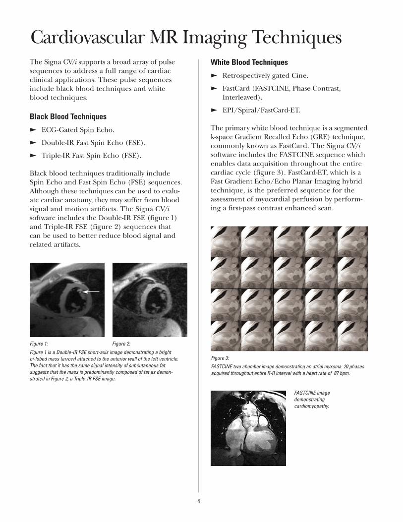
Black blood techniques traditionally include Spin Echo and Fast Spin Echo (FSE) sequences.Although these techniques can be used to evalu-ate cardiac anatomy, they may suffer from bloodsignal and motion artifacts. The Signa CV/isoftware includes the Double-IR FSE (figure 1)and Triple-IR FSE (figure 2) sequences that can be used to better reduce blood signal andrelated artifacts.
White Blood Techniques
E Retrospectively gated Cine.
E FastCard (FASTCINE, Phase Contrast,Interleaved).
E EPI/Spiral/FastCard-ET.
The primary white blood technique is a segmentedk-space Gradient Recalled Echo (GRE) technique,commonly known as FastCard. The Signa CV/isoftware includes the FASTCINE sequence whichenables data acquisition throughout the entirecardiac cycle (figure 3). FastCard-ET, which is aFast Gradient Echo/Echo Planar Imaging hybridtechnique, is the preferred sequence for theassessment of myocardial perfusion by perform-ing a first-pass contrast enhanced scan.
Figure 3:
FASTCINE two chamber image demonstrating an atrial myxoma. 20 phasesacquired throughout entire R-R interval with a heart rate of 87 bpm.
4
FASTCINE imagedemonstrating cardiomyopathy.
Figure 1: Figure 2:
Figure 1 is a Double-IR FSE short-axis image demonstrating a bright bi-lobed mass (arrow) attached to the anterior wall of the left ventricle.The fact that it has the same signal intensity of subcutaneous fat suggests that the mass is predominantly composed of fat as demon-strated in Figure 2, a Triple-IR FSE image.
Cardiovascular MR Imaging Techniques
Black Blood Techniques
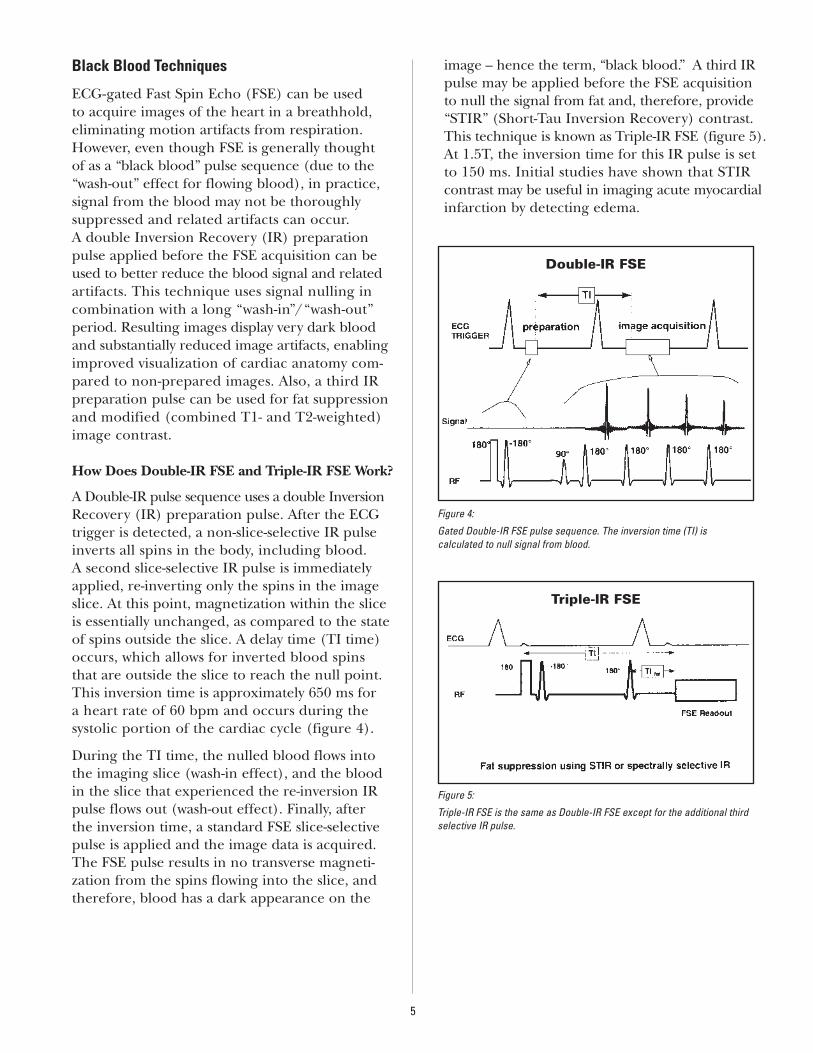
ECG-gated Fast Spin Echo (FSE) can be used to acquire images of the heart in a breathhold,eliminating motion artifacts from respiration.However, even though FSE is generally thought of as a “black blood” pulse sequence (due to the“wash-out” effect for flowing blood), in practice, signal from the blood may not be thoroughly suppressed and related artifacts can occur. A double Inversion Recovery (IR) preparationpulse applied before the FSE acquisition can beused to better reduce the blood signal and relatedartifacts. This technique uses signal nulling incombination with a long “wash-in”/“wash-out”period. Resulting images display very dark bloodand substantially reduced image artifacts, enablingimproved visualization of cardiac anatomy com-pared to non-prepared images. Also, a third IRpreparation pulse can be used for fat suppressionand modified (combined T1- and T2-weighted)image contrast.
How Does Double-IR FSE and Triple-IR FSE Work?
A Double-IR pulse sequence uses a double InversionRecovery (IR) preparation pulse. After the ECGtrigger is detected, a non-slice-selective IR pulseinverts all spins in the body, including blood. A second slice-selective IR pulse is immediatelyapplied, re-inverting only the spins in the imageslice. At this point, magnetization within the sliceis essentially unchanged, as compared to the stateof spins outside the slice. A delay time (TI time)occurs, which allows for inverted blood spinsthat are outside the slice to reach the null point.This inversion time is approximately 650 ms for a heart rate of 60 bpm and occurs during the systolic portion of the cardiac cycle (figure 4).
During the TI time, the nulled blood flows intothe imaging slice (wash-in effect), and the bloodin the slice that experienced the re-inversion IRpulse flows out (wash-out effect). Finally, after the inversion time, a standard FSE slice-selectivepulse is applied and the image data is acquired.The FSE pulse results in no transverse magneti-zation from the spins flowing into the slice, andtherefore, blood has a dark appearance on the
image – hence the term, “black blood.” A third IRpulse may be applied before the FSE acquisitionto null the signal from fat and, therefore, provide“STIR” (Short-Tau Inversion Recovery) contrast.This technique is known as Triple-IR FSE (figure 5).At 1.5T, the inversion time for this IR pulse is setto 150 ms. Initial studies have shown that STIRcontrast may be useful in imaging acute myocardialinfarction by detecting edema.
5
Figure 4:
Gated Double-IR FSE pulse sequence. The inversion time (TI) is calculated to null signal from blood.
Figure 5:
Triple-IR FSE is the same as Double-IR FSE except for the additional thirdselective IR pulse.
Double-IR FSE
Triple-IR FSE
When Would I Use a Black Blood Sequence?
Breathheld gated Double/Triple-IR images provide excellent delineation of cardiac anatomywith minimal respiratory artifacts. Clinical appli-cations of this technique include:
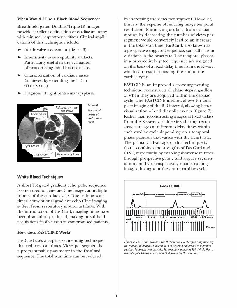
E Aortic valve assessment (figure 6).
E Insensitivity to susceptibility artifacts. Particularly useful in the evaluation of post-op congenital heart disease.
E Characterization of cardiac masses (achieved by extending the TE to 60 or 80 ms).
E Diagnosis of right ventricular dysplasia.
White Blood Techniques
A short TR gated gradient echo pulse sequenceis often used to generate Cine images at multipleframes of the cardiac cycle. Due to long scantimes, conventional gradient echo Cine imagingsuffers from respiratory motion artifacts. Withthe introduction of FastCard, imaging times havebeen dramatically reduced, making breathheldacquisitions feasible even in compromised patients.
How does FASTCINE Work?
FastCard uses a k-space segmenting techniquethat reduces scan times. Views per segment is a programmable parameter in the FastCardsequence. The total scan time can be reduced
by increasing the views per segment. However,this is at the expense of reducing image temporal resolution. Minimizing artifacts from cardiacmotion by decreasing the number of views persegment would conversely lead to an increase in the total scan time. FastCard, also known as a prospective triggered sequence, can suffer fromvariations in the heart rate. The temporal phasesin a prospectively gated sequence are assigned on the basis of a fixed delay time from the R wave,which can result in missing the end of the cardiac cycle.
FASTCINE, an improved k-space segmentingtechnique, reconstructs all phase steps regardless of when they are acquired within the cardiaccycle. The FASTCINE method allows for com-plete imaging of the R-R interval, allowing better visualization of end diastolic events (figure 7).Rather than reconstructing images at fixed delaysfrom the R wave, variable view sharing recon-structs images at different delay times withineach cardiac cycle depending on a temporalphase position that varies with the heart rate. The primary advantage of this technique is that it combines the strengths of FastCard andCINE, respectively, by enabling shorter scan timesthrough prospective gating and k-space segmen-tation and by retrospectively reconstructingimages throughout the entire cardiac cycle.
6
Figure 6:
Transaxial image at aortic valve level.
FASTCINE
Phases
Figure 7: FASTCINE divides each R-R interval evenly upon programmingthe number of phases. K-space data is resorted according to temporalposition in systole and diastole. For example: phase at 60% (circled) intodiastole gets k-lines at around 60% diastole for R-R interval.
Aortic Valve
Pulmonary Arteryand Valve
Right Atrium
Left Atrium Descending Aorta
When Would I Use a White Blood Sequence?
Clinical applications are widespread with thistechnique for the heart. Depending on the imaging plane selected, global heart function can be assessed. Clinical applications of this technique include:
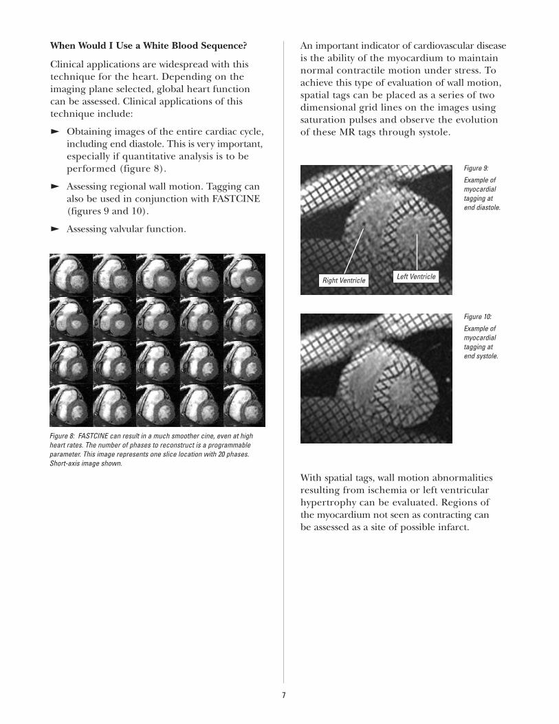
E Obtaining images of the entire cardiac cycle, including end diastole. This is very important,especially if quantitative analysis is to be performed (figure 8).
E Assessing regional wall motion. Tagging canalso be used in conjunction with FASTCINE(figures 9 and 10).
E Assessing valvular function.
An important indicator of cardiovascular disease is the ability of the myocardium to maintainnormal contractile motion under stress. Toachieve this type of evaluation of wall motion,spatial tags can be placed as a series of twodimensional grid lines on the images using saturation pulses and observe the evolution of these MR tags through systole.
With spatial tags, wall motion abnormalitiesresulting from ischemia or left ventricular hypertrophy can be evaluated. Regions of the myocardium not seen as contracting can be assessed as a site of possible infarct.
7
Figure 8: FASTCINE can result in a much smoother cine, even at highheart rates. The number of phases to reconstruct is a programmableparameter. This image represents one slice location with 20 phases.Short-axis image shown.
Figure 10:
Example ofmyocardial tagging at end systole.
Figure 9:
Example ofmyocardial tagging at end diastole.
Right Ventricle Left Ventricle
Perfusion
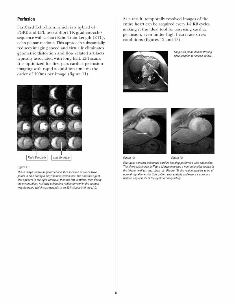
FastCard EchoTrain, which is a hybrid of FGRE and EPI, uses a short TR gradient-echosequence with a short Echo Train Length (ETL),echo planar readout. This approach substantiallyreduces imaging speed and virtually eliminatesgeometric distortion and flow related artifactstypically associated with long ETL EPI scans. It is optimized for first pass cardiac perfusionimaging with rapid acquisition time on the order of 100ms per image (figure 11).
As a result, temporally resolved images of theentire heart can be acquired every 1-2 RR cycles,making it the ideal tool for assessing cardiacperfusion, even under high heart rate stressconditions (figures 12 and 13).
8
Figure 11:
These images were acquired at one slice location at successive points in time during a dipyridamole stress test. The contrast agent first appears in the right ventricle, then the left ventricle, then finallythe myocardium. A slowly enhancing region (arrow) in the septum was detected which corresponds to an 80% stenosis of the LAD.
Right Ventricle Left Ventricle
Long-axis plane demonstratingslice location for image below.
Figure 12: Figure 13:
First-pass contrast-enhanced cardiac imaging performed with adenosine.The short-axis image in Figure 12 demonstrates a non-enhancing region inthe inferior wall (arrow). Upon rest (Figure 13), the region appears to be ofnormal signal intensity. This patient successfully underwent a coronaryballoon angioplasty of the right coronary artery.
To perform cardiovascular MR procedures effectively, it is important to understand the patient’s diseaseprocess. And, to understand the disease process, a fundamental understanding of cardiac anatomy and physiology is critical.
Cardiac AnatomyThe adult heart weighs about 9 ounces (300 g),holds approximately 500 ml of blood and beatsabout 100,000 times each day to push almost2,000 gallons of blood through about 65,000miles of blood vessels. It’s a complex, interestingorgan to image. It is located in the mediastinum,above the diaphragm and between the lungs.
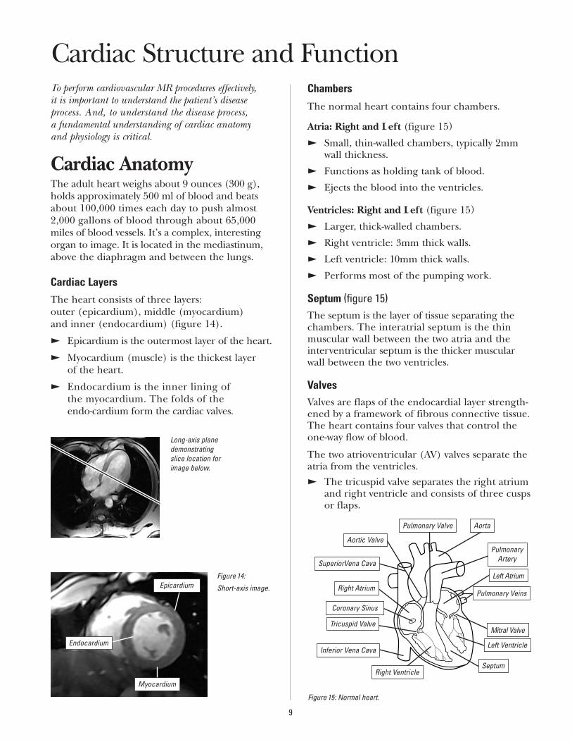
Cardiac LayersThe heart consists of three layers: outer (epicardium), middle (myocardium) and inner (endocardium) (figure 14).
E Epicardium is the outermost layer of the heart.
E Myocardium (muscle) is the thickest layer of the heart.
E Endocardium is the inner lining of the myocardium. The folds of the endo-cardium form the cardiac valves.
Chambers
The normal heart contains four chambers.
Atria: Right and Left (figure 15)
E Small, thin-walled chambers, typically 2mmwall thickness.
E Functions as holding tank of blood.
E Ejects the blood into the ventricles.
Ventricles: Right and Left (figure 15)
E Larger, thick-walled chambers.
E Right ventricle: 3mm thick walls.
E Left ventricle: 10mm thick walls.
E Performs most of the pumping work.
Septum (figure 15)The septum is the layer of tissue separating thechambers. The interatrial septum is the thin muscular wall between the two atria and theinterventricular septum is the thicker muscularwall between the two ventricles.
ValvesValves are flaps of the endocardial layer strength-ened by a framework of fibrous connective tissue.The heart contains four valves that control theone-way flow of blood.
The two atrioventricular (AV) valves separate theatria from the ventricles. E The tricuspid valve separates the right atrium
and right ventricle and consists of three cuspsor flaps.
9
Cardiac Structure and Function
Figure 14:
Short-axis image.Epicardium
Endocardium
Long-axis planedemonstratingslice location forimage below.
Myocardium
Figure 15: Normal heart.
Pulmonary Artery
Pulmonary Valve Aorta
Mitral Valve
Left Atrium
SeptumRight Ventricle
Tricuspid Valve
Right Atrium
Coronary Sinus
Pulmonary Veins
Inferior Vena Cava
SuperiorVena Cava
Left Ventricle
Aortic Valve
E The bicuspid (or mitral) valve separates theleft atrium and left ventricle and consists oftwo cusps or flaps.
Cordae tendineae anchor valve cusps to the papillary muscles of the ventricles. They preventthe valves from opening into the atria during ventricular contraction.
There are two semilunar valves which are half-moon shaped.
E The pulmonary valve, located inside the pul-monary artery, controls blood flow betweenthe right ventricle and pulmonary artery.
E The aortic valve regulates blood flow betweenthe left ventricle and aorta.
Each semilunar valve consists of three cusps that look like shallow cups cut in half vertically,with the cut edges attached to the vessel wall.These valves have different functions during contraction and relaxation also known as systoleand diastole.
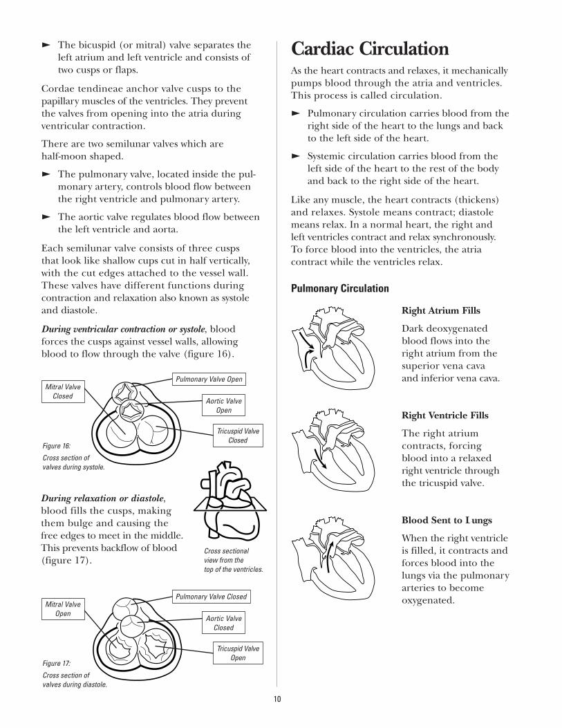
During ventricular contraction or systole, bloodforces the cusps against vessel walls, allowingblood to flow through the valve (figure 16).
Cardiac CirculationAs the heart contracts and relaxes, it mechanicallypumps blood through the atria and ventricles.This process is called circulation.
E Pulmonary circulation carries blood from theright side of the heart to the lungs and backto the left side of the heart.
E Systemic circulation carries blood from theleft side of the heart to the rest of the bodyand back to the right side of the heart.
Like any muscle, the heart contracts (thickens)and relaxes. Systole means contract; diastolemeans relax. In a normal heart, the right and left ventricles contract and relax synchronously. To force blood into the ventricles, the atria contract while the ventricles relax.
Pulmonary Circulation
Right Atrium Fills
Dark deoxygenatedblood flows into theright atrium from thesuperior vena cava and inferior vena cava.
Right Ventricle Fills
The right atrium contracts, forcing blood into a relaxedright ventricle throughthe tricuspid valve.
Blood Sent to Lungs
When the right ventricleis filled, it contracts andforces blood into thelungs via the pulmonaryarteries to become oxygenated.
10
Mitral ValveClosed
Figure 16:
Cross section of valves during systole.
Pulmonary Valve Open
Aortic ValveOpen
Tricuspid ValveClosed
Mitral ValveOpen
Figure 17:
Cross section of valves during diastole.
Pulmonary Valve Closed
Aortic ValveClosed
Tricuspid ValveOpen
During relaxation or diastole,blood fills the cusps, makingthem bulge and causing the free edges to meet in the middle.This prevents backflow of blood(figure 17).
Cross sectional view from the top of the ventricles.
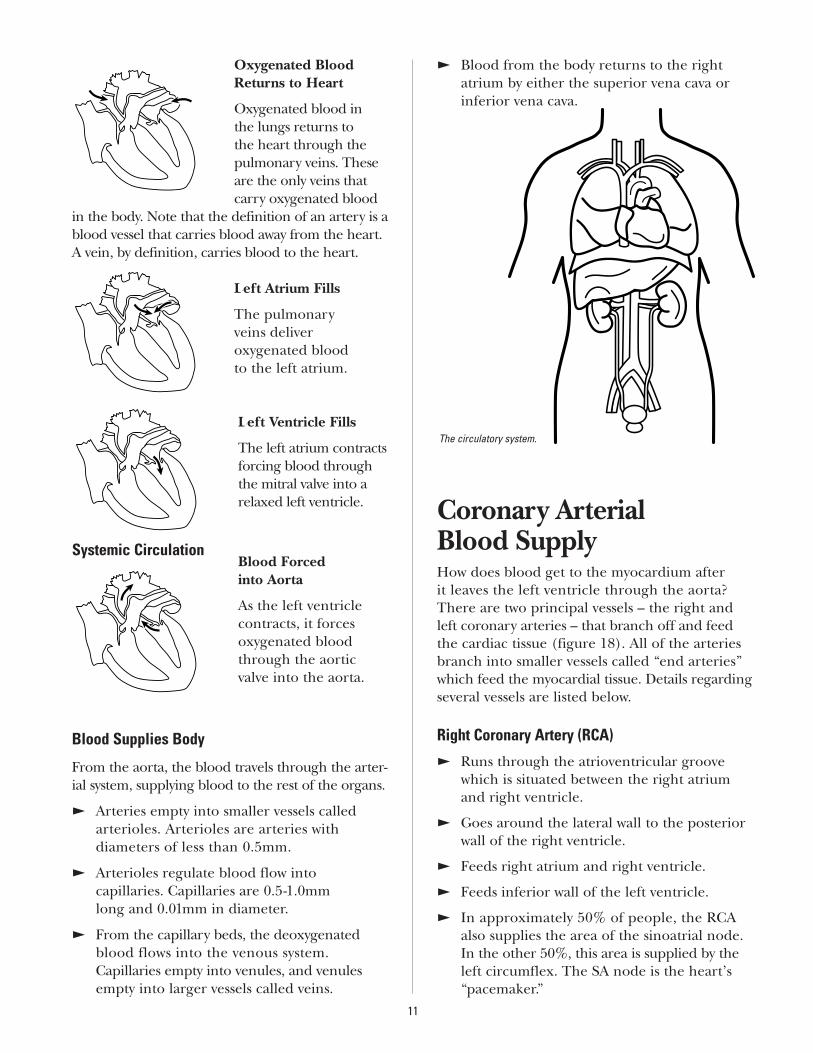
Oxygenated Blood Returns to Heart
Oxygenated blood in the lungs returns to the heart through thepulmonary veins. These are the only veins thatcarry oxygenated blood
in the body. Note that the definition of an artery is ablood vessel that carries blood away from the heart.A vein, by definition, carries blood to the heart.
Left Atrium Fills
The pulmonary veins deliver oxygenated blood to the left atrium.
Left Ventricle Fills
The left atrium contractsforcing blood throughthe mitral valve into arelaxed left ventricle.
Blood Forced into Aorta
As the left ventriclecontracts, it forces oxygenated bloodthrough the aortic valve into the aorta.
Blood Supplies Body
From the aorta, the blood travels through the arter-ial system, supplying blood to the rest of the organs.
E Arteries empty into smaller vessels called arterioles. Arterioles are arteries with diameters of less than 0.5mm.
E Arterioles regulate blood flow into capillaries. Capillaries are 0.5-1.0mm long and 0.01mm in diameter.
E From the capillary beds, the deoxygenatedblood flows into the venous system.Capillaries empty into venules, and venulesempty into larger vessels called veins.
E Blood from the body returns to the right atrium by either the superior vena cava orinferior vena cava.
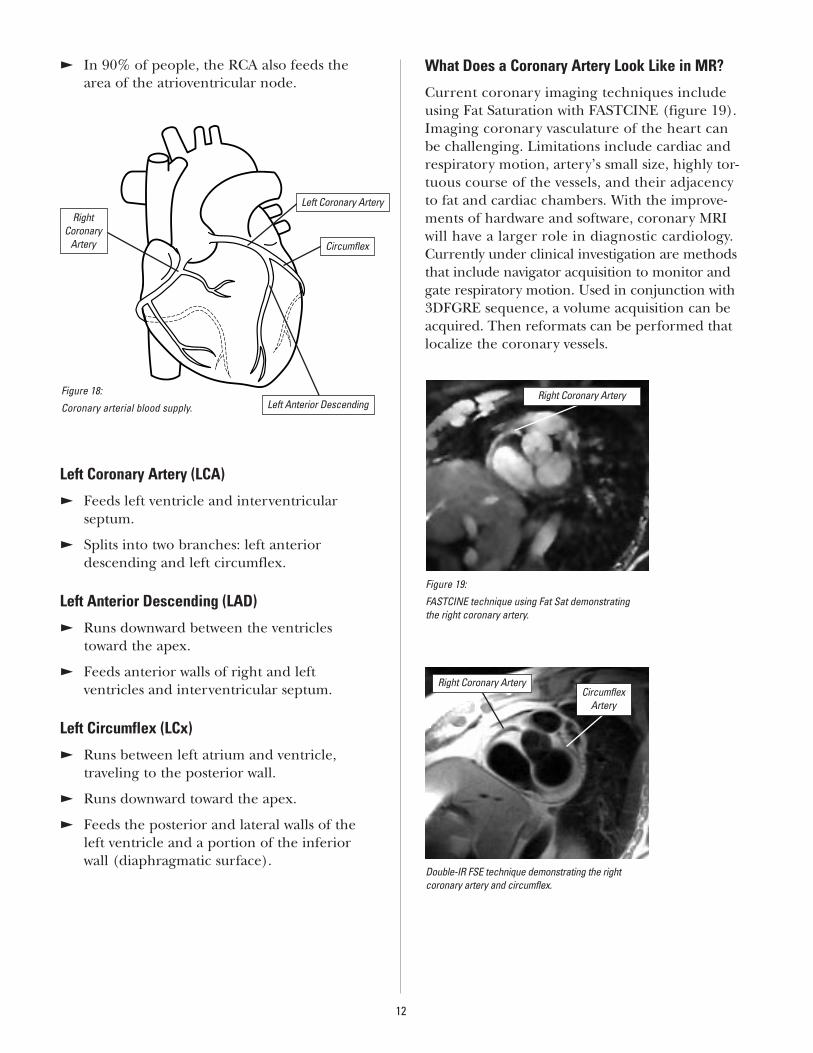
Coronary Arterial Blood SupplyHow does blood get to the myocardium after it leaves the left ventricle through the aorta?There are two principal vessels – the right andleft coronary arteries – that branch off and feedthe cardiac tissue (figure 18). All of the arteriesbranch into smaller vessels called “end arteries”which feed the myocardial tissue. Details regardingseveral vessels are listed below.
Right Coronary Artery (RCA)
E Runs through the atrioventricular groovewhich is situated between the right atriumand right ventricle.
E Goes around the lateral wall to the posteriorwall of the right ventricle.
E Feeds right atrium and right ventricle.
E Feeds inferior wall of the left ventricle.
E In approximately 50% of people, the RCAalso supplies the area of the sinoatrial node.In the other 50%, this area is supplied by theleft circumflex. The SA node is the heart’s“pacemaker.”
11
The circulatory system.
Systemic Circulation
E In 90% of people, the RCA also feeds thearea of the atrioventricular node.
Left Coronary Artery (LCA)
E Feeds left ventricle and interventricular septum.
E Splits into two branches: left anteriordescending and left circumflex.
Left Anterior Descending (LAD)
E Runs downward between the ventriclestoward the apex.
E Feeds anterior walls of right and left ventricles and interventricular septum.
Left Circumflex (LCx)
E Runs between left atrium and ventricle, traveling to the posterior wall.
E Runs downward toward the apex.
E Feeds the posterior and lateral walls of theleft ventricle and a portion of the inferiorwall (diaphragmatic surface).
What Does a Coronary Artery Look Like in MR?
Current coronary imaging techniques includeusing Fat Saturation with FASTCINE (figure 19).Imaging coronary vasculature of the heart can be challenging. Limitations include cardiac andrespiratory motion, artery’s small size, highly tor-tuous course of the vessels, and their adjacencyto fat and cardiac chambers. With the improve-ments of hardware and software, coronary MRIwill have a larger role in diagnostic cardiology.Currently under clinical investigation are methodsthat include navigator acquisition to monitor andgate respiratory motion. Used in conjunction with3DFGRE sequence, a volume acquisition can beacquired. Then reformats can be performed thatlocalize the coronary vessels.
12
Figure 18:
Coronary arterial blood supply.
Right Coronary
Artery
Left Coronary Artery
Circumflex
Left Anterior Descending
Figure 19:
FASTCINE technique using Fat Sat demonstrating the right coronary artery.
Double-IR FSE technique demonstrating the right coronary artery and circumflex.
Right Coronary Artery
Right Coronary ArteryCircumflex
Artery
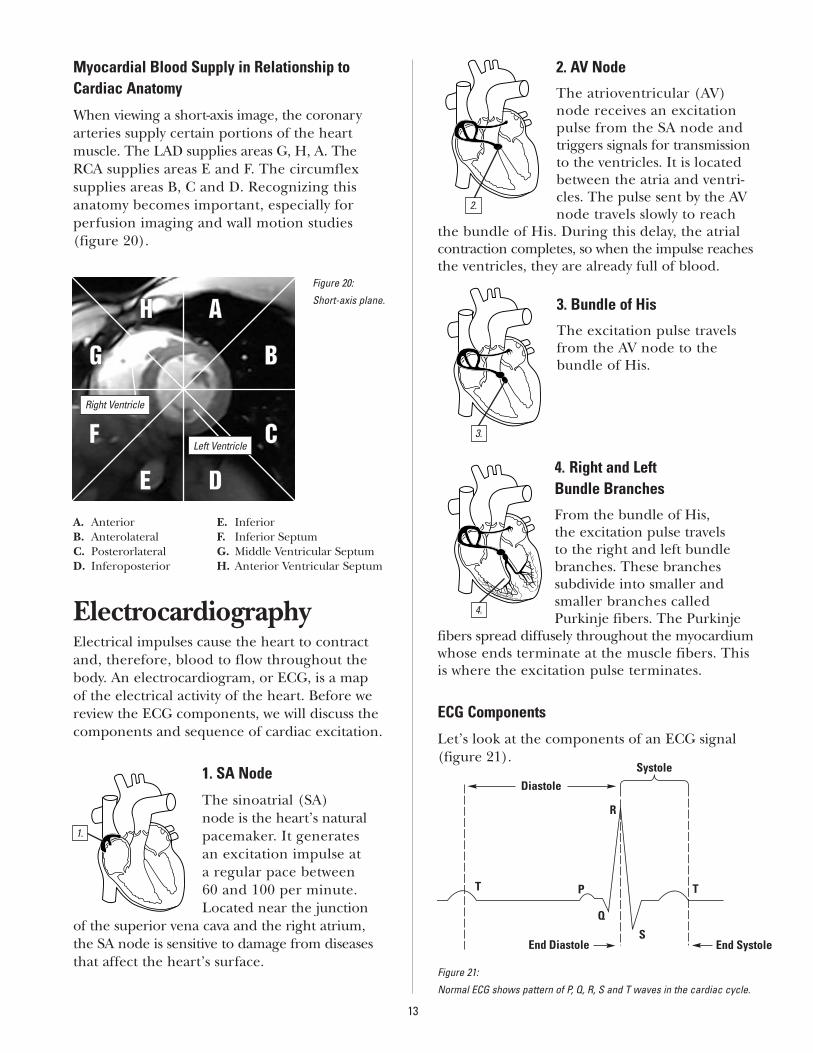
Myocardial Blood Supply in Relationship toCardiac Anatomy
When viewing a short-axis image, the coronaryarteries supply certain portions of the heart muscle. The LAD supplies areas G, H, A. TheRCA supplies areas E and F. The circumflex supplies areas B, C and D. Recognizing thisanatomy becomes important, especially for perfusion imaging and wall motion studies (figure 20).
A. Anterior E. InferiorB. Anterolateral F. Inferior SeptumC. Posterorlateral G. Middle Ventricular SeptumD. Inferoposterior H. Anterior Ventricular Septum
ElectrocardiographyElectrical impulses cause the heart to contractand, therefore, blood to flow throughout thebody. An electrocardiogram, or ECG, is a map of the electrical activity of the heart. Before wereview the ECG components, we will discuss thecomponents and sequence of cardiac excitation.
1. SA Node
The sinoatrial (SA)node is the heart’s naturalpacemaker. It generates an excitation impulse at a regular pace between 60 and 100 per minute.Located near the junction
of the superior vena cava and the right atrium,the SA node is sensitive to damage from diseasesthat affect the heart’s surface.
2. AV Node
The atrioventricular (AV)node receives an excitationpulse from the SA node andtriggers signals for transmissionto the ventricles. It is locatedbetween the atria and ventri-cles. The pulse sent by the AVnode travels slowly to reach
the bundle of His. During this delay, the atrialcontraction completes, so when the impulse reachesthe ventricles, they are already full of blood.
3. Bundle of His
The excitation pulse travelsfrom the AV node to the bundle of His.
4. Right and Left Bundle Branches
From the bundle of His, the excitation pulse travels to the right and left bundlebranches. These branches subdivide into smaller andsmaller branches calledPurkinje fibers. The Purkinje
fibers spread diffusely throughout the myocardiumwhose ends terminate at the muscle fibers. Thisis where the excitation pulse terminates.
ECG Components
Let’s look at the components of an ECG signal(figure 21).
13
Figure 20:
Short-axis plane.AAHH
BB
CC
DDEE
FF
GG
Right Ventricle
Left Ventricle
1.
2.
Figure 21:
Normal ECG shows pattern of P, Q, R, S and T waves in the cardiac cycle.
3.
4.
Diastole
Systole
T
R
PT
Q
SEnd SystoleEnd Diastole
P Wave
The P Wave represents the original pacemakingimpulse from the SAnode, which spreadsthrough the atria.
A normal P wave is no more than 3mm high and .12 seconds in duration. Keep in mind that it is difficult and sometimes impossible to see the P wave from an ECG acquired when the patient is inside the magnet.
PR Interval
This is the time between the onset of the P wave and the onset of the QRS complex. The normal
PR interval is .12 to .20 seconds. Anything greater than .20 seconds is abnormal.
QRS Complex
The QRS complex repre-sents the depolarization of the right and left ventricles. A normal QRS complex is about
.08 to .11 seconds in duration. A longer complexmay indicate a ventricular conduction defect,such as a left bundle branch block.
ST Segment
The ST segment represents the timebetween the comple-tion of a depolarizationand the beginning of
repolarization of the ventricle. An elevated ordepressed ST segment could indicate ischemiaor an infarction.
T Wave
The T wave represents the recovery phase afterventricular contraction. In cases of heart injury, the T wave may be
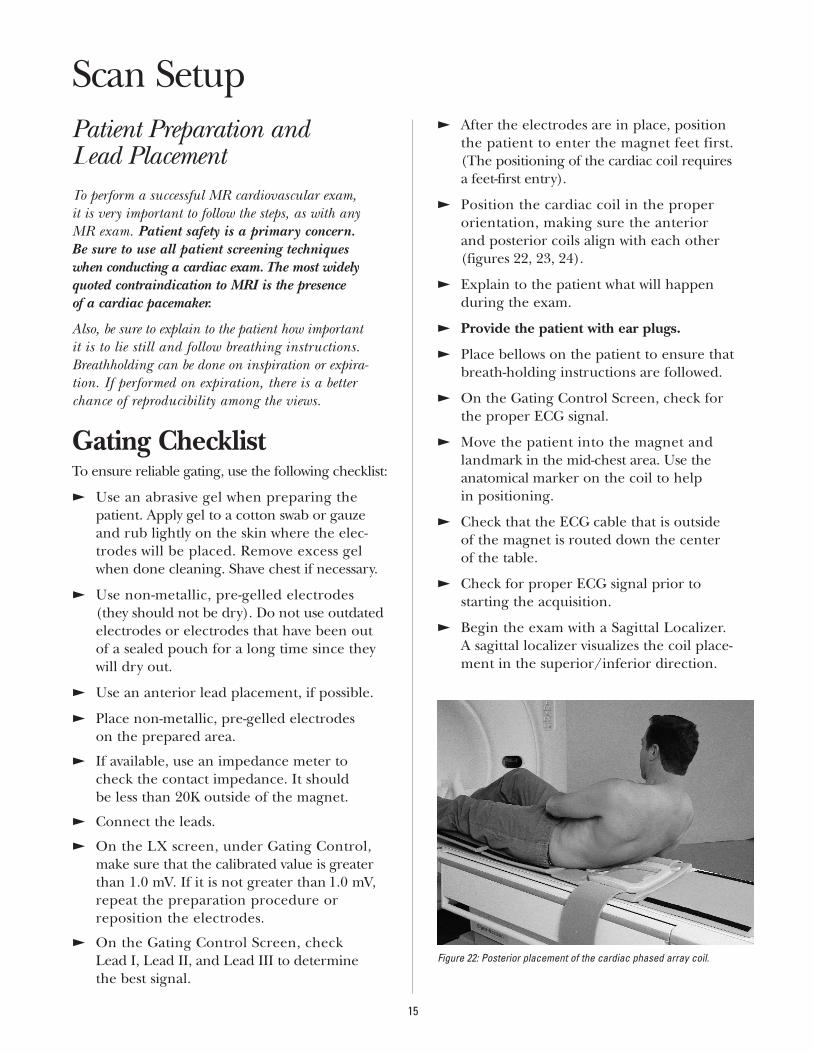
inverted. Flowing blood in the body makes anartifact in the ECG that obscures the normal T wave when the patient is inside the magnet.
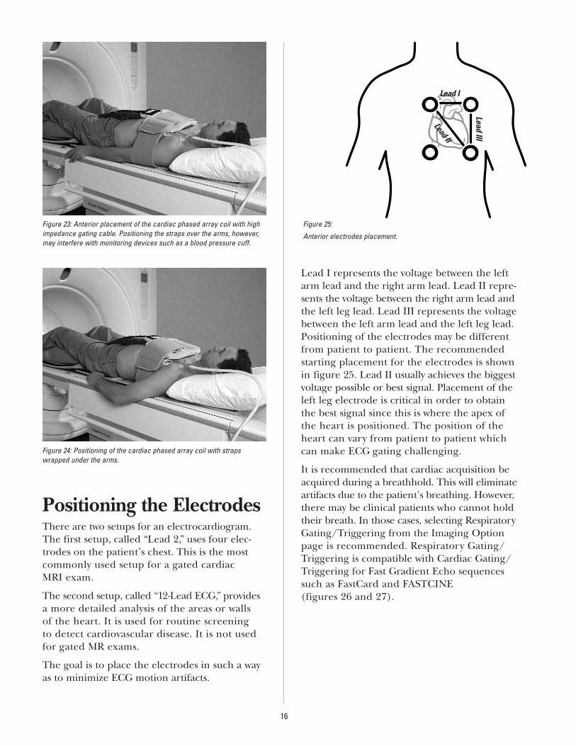
R to R IntervalThe R to R interval represents the time betweenone heartbeat and the next.
Abnormalities
Like cardiac anatomy, the heart’s electrical conduction system can be affected by disease.Abnormalities in the electrical activity are called arrhythmias.
In MR imaging, it’s important to keep data acquisition times short to avoid motion-relatedartifacts. For cardiac imaging, this means acquisition times under 150 ms. If we can’tacquire all k-space data to reconstruct an imagewithin a single R-R interval, then acquisitionmust be partitioned across several cardiac cycles,with each data segment acquired at the same cardiac phase. This synchronization of data acqui-sition to the cardiac cycle ensures that the heart is in the same spatial position or cardiac state foreach k-space-encoding segment. For this reason, it is important that the patient’s heartbeat is regular. It is particularly critical for FastCardapplications. As the heartbeat becomes moreirregular, the image quality decreases.
14
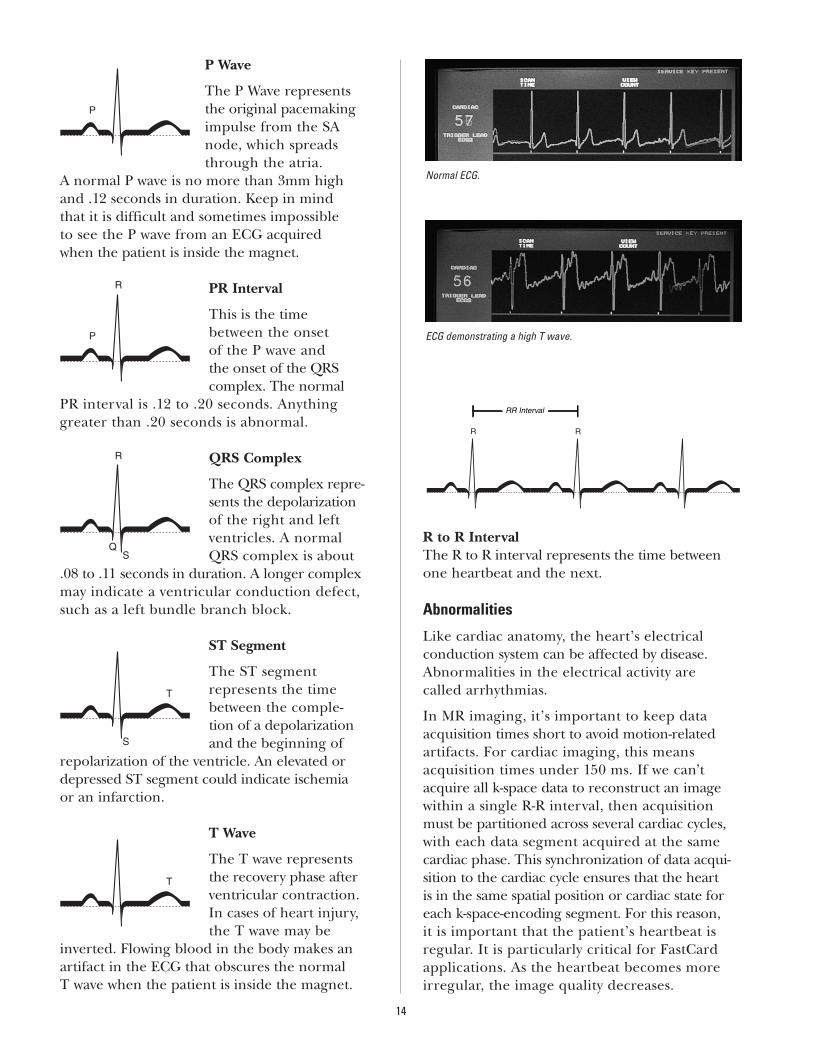
Normal ECG.
ECG demonstrating a high T wave.
Patient Preparation and Lead PlacementTo perform a successful MR cardiovascular exam, it is very important to follow the steps, as with any MR exam. Patient safety is a primary concern. Be sure to use all patient screening techniques when conducting a cardiac exam. The most widelyquoted contraindication to MRI is the presence of a cardiac pacemaker.
Also, be sure to explain to the patient how important it is to lie still and follow breathing instructions.Breathholding can be done on inspiration or expira-tion. If performed on expiration, there is a better chance of reproducibility among the views.
Gating ChecklistTo ensure reliable gating, use the following checklist:
E Use an abrasive gel when preparing thepatient. Apply gel to a cotton swab or gauzeand rub lightly on the skin where the elec-trodes will be placed. Remove excess gelwhen done cleaning. Shave chest if necessary.
E Use non-metallic, pre-gelled electrodes (they should not be dry). Do not use outdatedelectrodes or electrodes that have been outof a sealed pouch for a long time since theywill dry out.
E Use an anterior lead placement, if possible.
E Place non-metallic, pre-gelled electrodes on the prepared area.
E If available, use an impedance meter tocheck the contact impedance. It should be less than 20K outside of the magnet.
E Connect the leads.
E On the LX screen, under Gating Control,make sure that the calibrated value is greaterthan 1.0 mV. If it is not greater than 1.0 mV,repeat the preparation procedure or reposition the electrodes.
E On the Gating Control Screen, check Lead I, Lead II, and Lead III to determine the best signal.
E After the electrodes are in place, position the patient to enter the magnet feet first. (The positioning of the cardiac coil requires a feet-first entry).
E Position the cardiac coil in the proper orientation, making sure the anterior and posterior coils align with each other (figures 22, 23, 24).
E Explain to the patient what will happen during the exam.
E Provide the patient with ear plugs.
E Place bellows on the patient to ensure that breath-holding instructions are followed.
E On the Gating Control Screen, check for the proper ECG signal.
E Move the patient into the magnet and landmark in the mid-chest area. Use theanatomical marker on the coil to help in positioning.
E Check that the ECG cable that is outside of the magnet is routed down the center of the table.
E Check for proper ECG signal prior to starting the acquisition.
E Begin the exam with a Sagittal Localizer. A sagittal localizer visualizes the coil place-ment in the superior/inferior direction.
15
Scan Setup
Figure 22: Posterior placement of the cardiac phased array coil.
Positioning the ElectrodesThere are two setups for an electrocardiogram.The first setup, called “Lead 2,” uses four elec-trodes on the patient’s chest. This is the mostcommonly used setup for a gated cardiac MRI exam.
The second setup, called “12-Lead ECG,” providesa more detailed analysis of the areas or walls of the heart. It is used for routine screening to detect cardiovascular disease. It is not used for gated MR exams.
The goal is to place the electrodes in such a wayas to minimize ECG motion artifacts.
Lead I represents the voltage between the leftarm lead and the right arm lead. Lead II repre-sents the voltage between the right arm lead andthe left leg lead. Lead III represents the voltagebetween the left arm lead and the left leg lead.Positioning of the electrodes may be differentfrom patient to patient. The recommended starting placement for the electrodes is shownin figure 25. Lead II usually achieves the biggestvoltage possible or best signal. Placement of theleft leg electrode is critical in order to obtain the best signal since this is where the apex of the heart is positioned. The position of the heart can vary from patient to patient which can make ECG gating challenging.
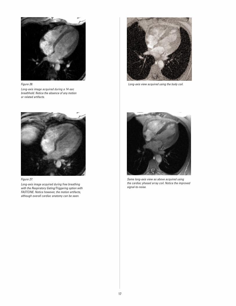
It is recommended that cardiac acquisition beacquired during a breathhold. This will eliminateartifacts due to the patient’s breathing. However,there may be clinical patients who cannot holdtheir breath. In those cases, selecting RespiratoryGating/Triggering from the Imaging Optionpage is recommended. Respiratory Gating/Triggering is compatible with Cardiac Gating/Triggering for Fast Gradient Echo sequencessuch as FastCard and FASTCINE (figures 26 and 27).
16
Figure 25:
Anterior electrodes placement.
Lead I
Lead II
Lead III
Figure 23: Anterior placement of the cardiac phased array coil with highimpedance gating cable. Positioning the straps over the arms, however,may interfere with monitoring devices such as a blood pressure cuff.
Figure 24: Positioning of the cardiac phased array coil with strapswrapped under the arms.
17
Figure 26:
Long-axis image acquired during a 14-sec breathhold. Notice the absence of any motion or related artifacts.
Figure 27:
Long-axis image acquired during free breathingwith the Respiratory Gating/Triggering option withFASTCINE. Notice however, the motion artifacts,although overall cardiac anatomy can be seen.
Long-axis view acquired using the body coil.
Same long-axis view as above acquired using the cardiac phased array coil. Notice the improvedsignal-to-noise.
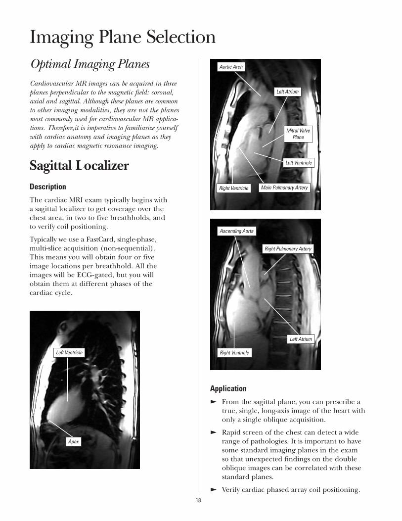
Optimal Imaging PlanesCardiovascular MR images can be acquired in threeplanes perpendicular to the magnetic field: coronal,axial and sagittal. Although these planes are common to other imaging modalities, they are not the planesmost commonly used for cardiovascular MR applica-tions. Therefore,it is imperative to familiarize yourselfwith cardiac anatomy and imaging planes as theyapply to cardiac magnetic resonance imaging.
Sagittal LocalizerDescription
The cardiac MRI exam typically begins with a sagittal localizer to get coverage over the chest area, in two to five breathholds, and to verify coil positioning.
Typically we use a FastCard, single-phase, multi-slice acquisition (non-sequential). This means you will obtain four or five image locations per breathhold. All the images will be ECG-gated, but you will obtain them at different phases of the cardiac cycle.
Application
E From the sagittal plane, you can prescribe atrue, single, long-axis image of the heart withonly a single oblique acquisition.
E Rapid screen of the chest can detect a widerange of pathologies. It is important to havesome standard imaging planes in the exam so that unexpected findings on the doubleoblique images can be correlated with thesestandard planes.
E Verify cardiac phased array coil positioning.18
Imaging Plane Selection
Apex
Right Pulmonary Artery
Ascending Aorta
Right Ventricle
Left Atrium
Right Ventricle Main Pulmonary Artery
Aortic Arch
Left Atrium
Mitral ValvePlane
Left Ventricle
Left Ventricle
19
How To
PARAMETER SCAN VALUE PARAMETER SCAN VALUE IMAGING OPTIONS GAT/RESP OPTIONS
Plane Sagittal Slice Thk 8mm Gat, FC Trig Type: Select Best Lead
Mode 2D Slice Space 0.0 Trig Win: 20
PSD FastCard SPGR Frequency 256 Trig Delay: Min
TE Minimum Phase/PFOV 128/0.75 Cardiac Phases: 1
TR N/A NEX 1 VPS: 8 to 12
Flip 20 degrees Freq. Direction S/I
RBW 31.25 Ctr. Frequency Water
FOV 40cm Auto Shim On
Comments
E Use Resp Gate/Trig for non-breathhold scans.
E Typically, scan from L120 to R50.
E After the patient has been moved into the magnet, use the Gating Control Screen to check which leadhas the best gating signal. This can be done realtime by clicking on the lead selection on the GatingControl Screen.
E While scanning the first set of locations, if you are finding that the gating algorithm is missing triggers,the following options can be tried without having to re-prescribe the scan:
J Reduce the trigger level and see if the performance is better.
J If the above fails, select the ECG Noise Filter. This changes the algorithm to the delayed mode which is more reliable.
E If the heart rate varies upon the patient holding his/her breath, increase the Trigger Window.
Long-Axis Localizer
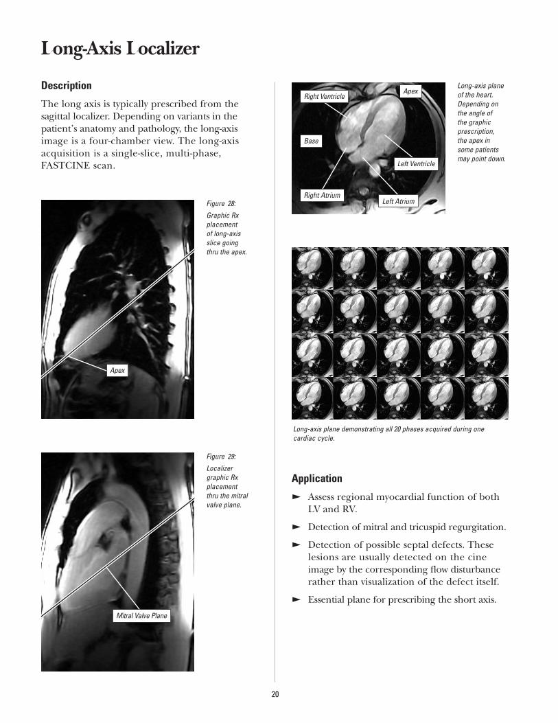
Description
The long axis is typically prescribed from thesagittal localizer. Depending on variants in thepatient’s anatomy and pathology, the long-axisimage is a four-chamber view. The long-axisacquisition is a single-slice, multi-phase, FASTCINE scan.
Application
E Assess regional myocardial function of bothLV and RV.
E Detection of mitral and tricuspid regurgitation.
E Detection of possible septal defects. Theselesions are usually detected on the cineimage by the corresponding flow disturbancerather than visualization of the defect itself.
E Essential plane for prescribing the short axis.
20
Figure 28:
Graphic Rx placement of long-axis slice going thru the apex.
Figure 29:
Localizer graphic Rx placement thru the mitralvalve plane.
Mitral Valve Plane
Long-axis planeof the heart.Depending on the angle of the graphic prescription, the apex in some patientsmay point down.
Long-axis plane demonstrating all 20 phases acquired during one cardiac cycle.
Apex
Base
Right Ventricle
Left Ventricle
Left AtriumRight Atrium
Apex
21
How To
PARAMETER SCAN VALUE PARAMETER SCAN VALUE IMAGING OPTIONS GAT/RESP OPTIONS
Plane Sagittal Slice Thk 8mm Gat, FC, Seq Trig Type: Select Best Lead
Mode 2D Slice Space 0.0 Trig Win: 20%
PSD FastCard SPGR Frequency 256 Trig Delay: Min
TE Minimum Full Phase/PFOV 128/0.75 Cardiac Phases: 20
TR N/A NEX 1 VPS: 4 to 8
Flip 15 degrees Freq. Direction Unswap
RBW 31.25 Ctr. Frequency Water
FOV 36-40cm Auto Shim On
Comments
E Adjust the VPS and number of locs before Pause for a breathhold scan.
E Number of Cardiac Phases to Recon: use Auto for FastCard and enter 20 for FASTCINE.
E Use Resp Gate/Trig for non-breathhold scans.
E Prescribe the slices parallel to the long axis of the left ventricle cavity. The graphic Rx line cursor should pass thru the mitral valve and the left ventricle apex. Hint: Once the apex is found: (1) save the series then copy paste the series; (2) open Graphic Rx, erase location; (3) locate the image that best depicts the mitral valve plane (figure 28); and (4) copy Rx to check for positioning thru mitralvalve plane (figure 29). (In some cases the apex and mitral valve may not line up; a compromise may be needed.)
E Give the breathhold instructions. Press [Scan] once the ECG signal has stabilized. Typically the stabilization takes about 2 seconds. For consistency, have patients hold their breath on expiration.
The following guidelines can be used to adjust the VPS depending upon the heart rate:
E BPM ≤60: use an 8 VPS.
E BPM 61-95: use a 6 VPS.
E BPM 96-125: use a 4 VPS.
E BPM 126-155: use a 2 VPS.
E BPM >156: use a 1 VPS.
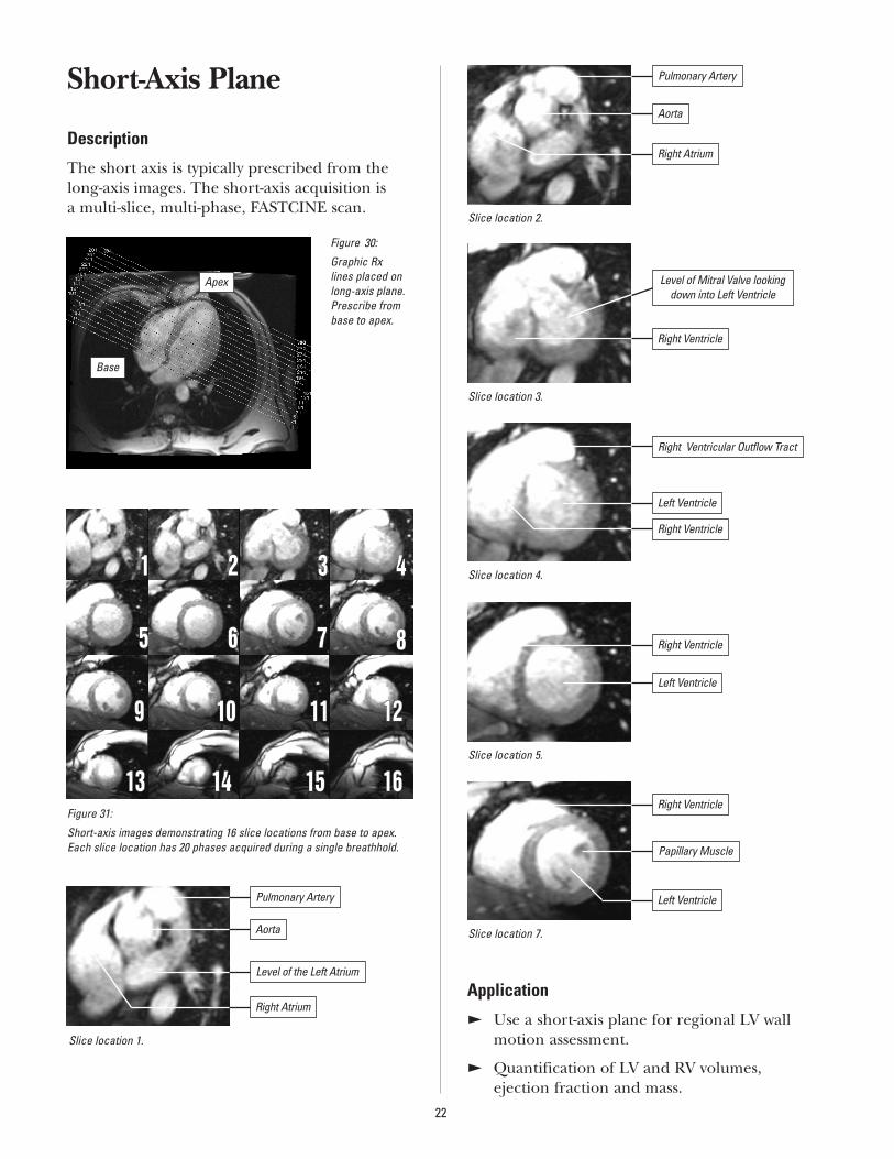
Short-Axis Plane
Description
The short axis is typically prescribed from thelong-axis images. The short-axis acquisition is a multi-slice, multi-phase, FASTCINE scan.
Application
E Use a short-axis plane for regional LV wallmotion assessment.
E Quantification of LV and RV volumes, ejection fraction and mass.
22
Figure 30:
Graphic Rx lines placed onlong-axis plane.Prescribe frombase to apex.
Figure 31:
Short-axis images demonstrating 16 slice locations from base to apex. Each slice location has 20 phases acquired during a single breathhold.
Slice location 1.
Apex
Base
11 22 33 44
55 66 77 88
99 1100 1111 1122
1133 1144 1155 1166
Aorta
Level of the Left Atrium
Right Atrium
Slice location 2.
Pulmonary Artery
Aorta
Right Atrium
Slice location 3.
Slice location 4.
Slice location 5.
Slice location 7.
Pulmonary Artery
Level of Mitral Valve lookingdown into Left Ventricle
Right Ventricle
Right Ventricular Outflow Tract
Left Ventricle
Right Ventricle
Right Ventricle
Left Ventricle
Right Ventricle
Papillary Muscle
Left Ventricle
23
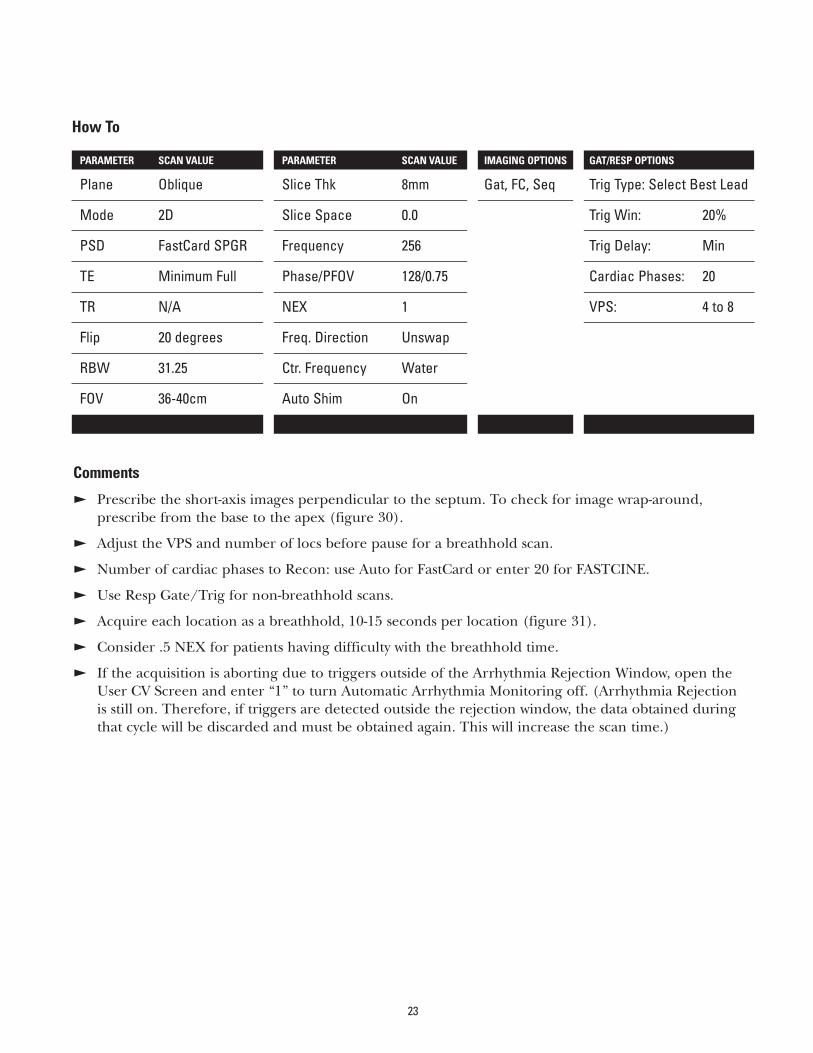
How To
PARAMETER SCAN VALUE PARAMETER SCAN VALUE IMAGING OPTIONS GAT/RESP OPTIONS
Plane Oblique Slice Thk 8mm Gat, FC, Seq Trig Type: Select Best Lead
Mode 2D Slice Space 0.0 Trig Win: 20%
PSD FastCard SPGR Frequency 256 Trig Delay: Min
TE Minimum Full Phase/PFOV 128/0.75 Cardiac Phases: 20
TR N/A NEX 1 VPS: 4 to 8
Flip 20 degrees Freq. Direction Unswap
RBW 31.25 Ctr. Frequency Water
FOV 36-40cm Auto Shim On
Comments
E Prescribe the short-axis images perpendicular to the septum. To check for image wrap-around,prescribe from the base to the apex (figure 30).
E Adjust the VPS and number of locs before pause for a breathhold scan.
E Number of cardiac phases to Recon: use Auto for FastCard or enter 20 for FASTCINE.
E Use Resp Gate/Trig for non-breathhold scans.
E Acquire each location as a breathhold, 10-15 seconds per location (figure 31).
E Consider .5 NEX for patients having difficulty with the breathhold time.
E If the acquisition is aborting due to triggers outside of the Arrhythmia Rejection Window, open the User CV Screen and enter “1” to turn Automatic Arrhythmia Monitoring off. (Arrhythmia Rejection is still on. Therefore, if triggers are detected outside the rejection window, the data obtained duringthat cycle will be discarded and must be obtained again. This will increase the scan time.)
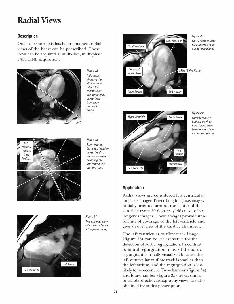
Radial Views
Description
Once the short axis has been obtained, radialviews of the heart can be prescribed. These views can be acquired as multi-slice, multi-phaseFASTCINE acquisition.
Application
Radial views are considered left ventricular long-axis images. Prescribing long-axis images radially oriented around the center of the ventricle every 30 degrees yields a set of six long-axis images. These images provide uni-formity of coverage of the left ventricle and give an overview of the cardiac chambers.
The left ventricular outflow track image (figure 36) can be very sensitive for the detection of aortic regurgitation. In contrast to mitral regurgitation, most of the aortic regurgitant is usually visualized because the left ventricular outflow track is smaller than the left atrium, and the regurgitation is less likely to be eccentric. Two-chamber (figure 34)and four-chamber (figure 35) views, similar to standard echocardiography views, are alsoobtained from this prescription.
24
Figure 32:
Axis plane showing the slice level inwhich the radial views are graphicallyprescribed from slice pictured below.
Figure 34:
Two chamber view(also referred to asa long-axis plane).
Figure 35:
Four chamber view(also referred to asa long-axis plane).
Figure 36:
Left ventricularoutflow track orparasternal view(also referred to asa long-axis plane).
Figure 33:
Start with the first slice location,prescribe thru the left ventriclebisecting the left ventricular outflow tract.
LeftVentricleOutflow
TractPosition
Left Atrium
Left Ventricle
Right Ventricle
Right Atrium
Tricuspid Valve Plane
Left Ventricle
Mitral Valve Plane
Left Atrium
Aortic Valve
Left Ventricle
Right Ventricle
Mitral Valve
Left Atrium
25
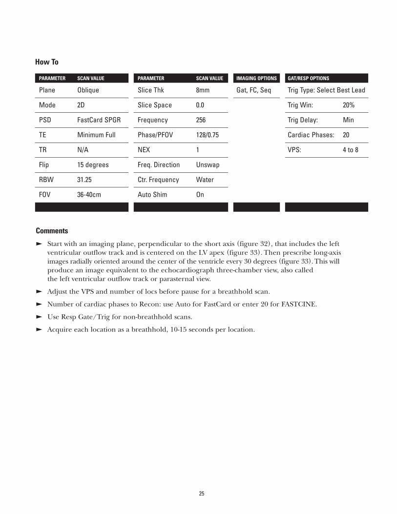
How To
PARAMETER SCAN VALUE PARAMETER SCAN VALUE IMAGING OPTIONS GAT/RESP OPTIONS
Plane Oblique Slice Thk 8mm Gat, FC, Seq Trig Type: Select Best Lead
Mode 2D Slice Space 0.0 Trig Win: 20%
PSD FastCard SPGR Frequency 256 Trig Delay: Min
TE Minimum Full Phase/PFOV 128/0.75 Cardiac Phases: 20
TR N/A NEX 1 VPS: 4 to 8
Flip 15 degrees Freq. Direction Unswap
RBW 31.25 Ctr. Frequency Water
FOV 36-40cm Auto Shim On
Comments
E Start with an imaging plane, perpendicular to the short axis (figure 32), that includes the left ventricular outflow track and is centered on the LV apex (figure 33). Then prescribe long-axis images radially oriented around the center of the ventricle every 30 degrees (figure 33). This will produce an image equivalent to the echocardiograph three-chamber view, also called the left ventricular outflow track or parasternal view.
E Adjust the VPS and number of locs before pause for a breathhold scan.
E Number of cardiac phases to Recon: use Auto for FastCard or enter 20 for FASTCINE.
E Use Resp Gate/Trig for non-breathhold scans.
E Acquire each location as a breathhold, 10-15 seconds per location.
Application
The coronal ascending aorta plane is used for assessment of:
E Ascending aorta pathology.
E Aortic regurgitation.
Coronal Ascending Aorta Plane
Description
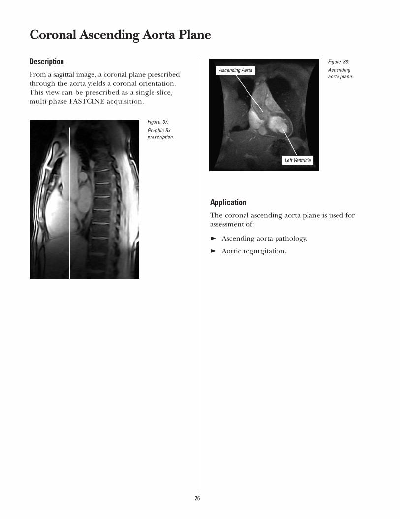
From a sagittal image, a coronal plane prescribed through the aorta yields a coronal orientation. This view can be prescribed as a single-slice, multi-phase FASTCINE acquisition.
26
Figure 37:
Graphic Rx prescription.
Figure 38:
Ascending aorta plane.
Ascending Aorta
Left Ventricle
27
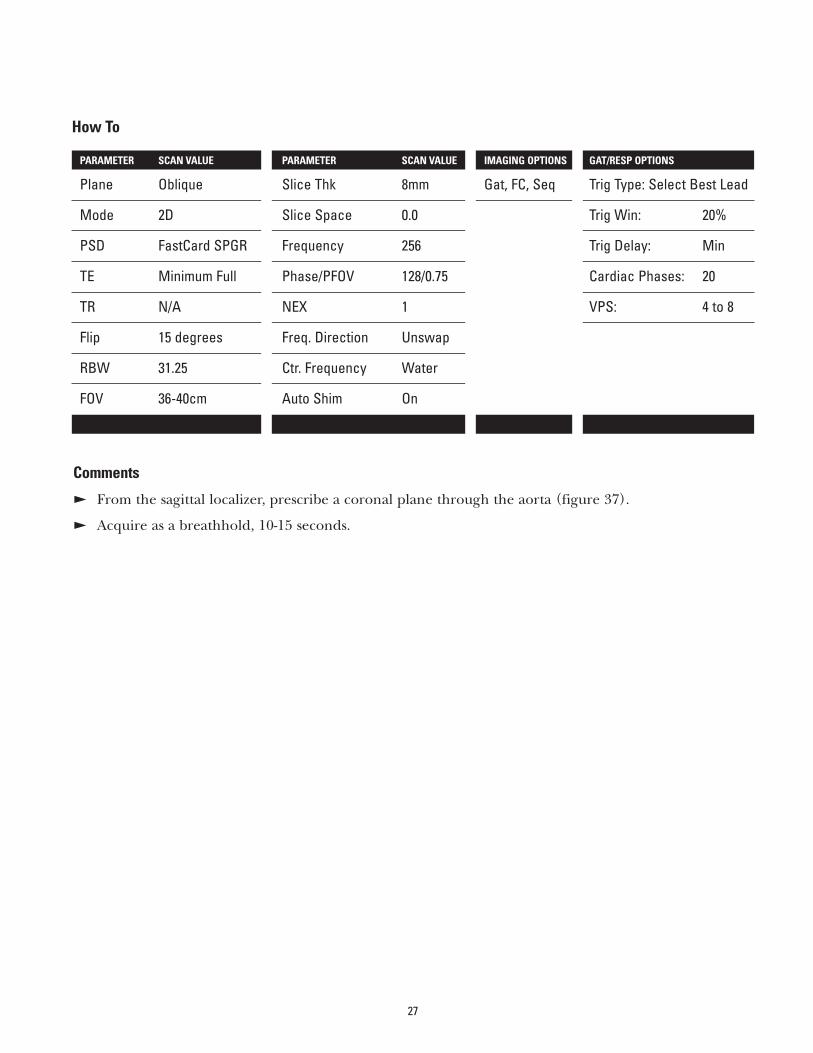
Comments
E From the sagittal localizer, prescribe a coronal plane through the aorta (figure 37).
E Acquire as a breathhold, 10-15 seconds.
How To
PARAMETER SCAN VALUE PARAMETER SCAN VALUE IMAGING OPTIONS GAT/RESP OPTIONS
Plane Oblique Slice Thk 8mm Gat, FC, Seq Trig Type: Select Best Lead
Mode 2D Slice Space 0.0 Trig Win: 20%
PSD FastCard SPGR Frequency 256 Trig Delay: Min
TE Minimum Full Phase/PFOV 128/0.75 Cardiac Phases: 20
TR N/A NEX 1 VPS: 4 to 8
Flip 15 degrees Freq. Direction Unswap
RBW 31.25 Ctr. Frequency Water
FOV 36-40cm Auto Shim On
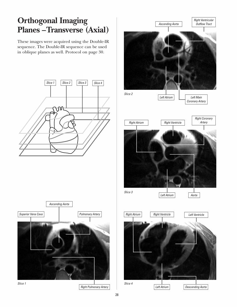
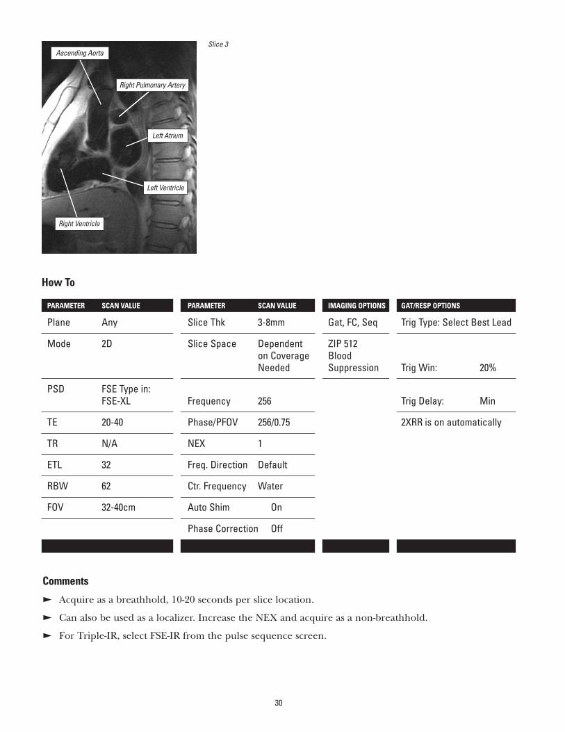
Orthogonal ImagingPlanes –Transverse (Axial)These images were acquired using the Double-IRsequence. The Double-IR sequence can be usedin oblique planes as well. Protocol on page 30.
28
Left Main Coronary Artery
Slice 1 Slice 2 Slice 3 Slice 4
Slice 1
Slice 2
Slice 3
Slice 4
Ascending Aorta
Superior Vena Cava
Ascending Aorta
Pulmonary Artery
Right Pulmonary Artery
Right VentricularOutflow Tract
Left Atrium
Right Atrium Right VentricleRight Coronary
Artery
AortaLeft Atrium
Right Atrium Right Ventricle Left Ventricle
Left Atrium Descending Aorta
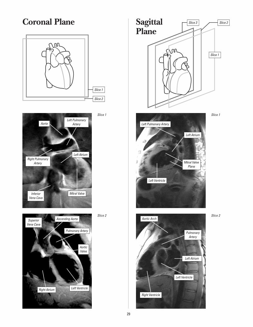
Coronal Plane Sagittal Plane
29
Slice 1
Inferior Vena Cava
SuperiorVena Cava
Right Pulmonary Artery
Left PulmonaryArteryAorta
Mitral Valve
Left Atrium
Slice 2
Right Atrium
Ascending Aorta
Pulmonary Artery
Aortic Valve
Left Ventricle
Slice 1
Left Pulmonary Artery
Left Atrium
Mitral ValvePlane
Left Ventricle
Slice 2
Right Ventricle
Aortic Arch
PulmonaryArtery
Left Atrium
Left Ventricle
Slice 1
Slice 2
Slice 1
Slice 2Slice 3
30
Slice 3
Right Ventricle
Ascending Aorta
Left Atrium
Left Ventricle
Comments
E Acquire as a breathhold, 10-20 seconds per slice location.
E Can also be used as a localizer. Increase the NEX and acquire as a non-breathhold.
E For Triple-IR, select FSE-IR from the pulse sequence screen.
How To
PARAMETER SCAN VALUE PARAMETER SCAN VALUE IMAGING OPTIONS GAT/RESP OPTIONS
Plane Any Slice Thk 3-8mm Gat, FC, Seq Trig Type: Select Best Lead
Mode 2D Slice Space Dependent ZIP 512on Coverage BloodNeeded Suppression Trig Win: 20%
PSD FSE Type in:FSE-XL Frequency 256 Trig Delay: Min
TE 20-40 Phase/PFOV 256/0.75 2XRR is on automatically
TR N/A NEX 1
ETL 32 Freq. Direction Default
RBW 62 Ctr. Frequency Water
FOV 32-40cm Auto Shim On
Phase Correction Off
Right Pulmonary Artery
Glossary of TermsAkinesis
Wall motion abnormality characterized by absentsystolic motion. Akinesia is generally associatedwith severe infarction or cardiomyopathy.
Aneurysm
A circumscribed sac caused by dilation of thewall of an artery, a vein or the heart wall.
Angina Pectoris
Severe constricting pain in the chest, often radiating to the left shoulder and arm and/or tothe jaw, due to myocardial infarct and ischemia.
Angiography
The roentgenographic visualization of blood vessels following the introduction of contrastmaterial; used as a diagnostic aid in conditionssuch as myocardial infarct and ischemia.
Apex of the Heart
The blunt rounded tip of the heart forming theleft ventricle. The apical portion of the ventricularmyocardium is thinner than other portions.
Arrhythmia
Any variation from the normal rhythm of theheartbeat.
Artifact
An error in the reconstructed image that doesnot correspond to the patient. Three majorforms of artifacts that can occur in MR imagingand cause poor image quality: geometric dis-tortion, inhomogeneous signal intensity, and spurious signal.
Base of the Heart
The region formed by the atrium and roots of the great vessels; thus, the “top” of the heart,located opposite the apex of the heart.
Beats per Minute (BPM)
The average heart rate as shown by the cardiacwaveform display.
Bundle Branch Block
A defect in the heart’s electrical conduction system in which there is a failure to conduct electricity down either the left or the right bundle of His.
Bundle Branches
The right and left conduction pathways con-tinuing from the bundle of His and proceedingalong both sides of the interventricular septumto the tips of the ventricles.
Cardiac Catheterization
The introduction of the catheter from outsidethe body, into the heart, through blood vessels.The catheter may be introduced into one of theheart’s chambers, or it may be guided into oneof the coronary arteries, or both.
Cardiac Output
Liters of blood pumped by each of the ventriclesper minute. Stroke Volume x Heart Rate.
Cardiomegaly
Enlargement of the heart.
Cardiomyopathy
Disease of the muscular wall of the heart which impedes filling and/or emptying of the cardiac chamber.
Cine
Software that lets you generate images for dynamic views of such anatomy as the heart. This option employs retrospective gating techniques and a Gradient Echo pulse sequence.
Congestive Heart Failure (CHF)
The syndrome of tissue congestion and edema that develops with failure of the heart to maintainadequate circulation of blood. The congestionmay occur in the lungs (pulmonary edema), inthe peripheral circulation, or in both, dependingon whether the failure is of the left ventricle,right ventricle, or both.
31
Coronal
The horizontal plane along the longitudinal axisof the body dividing it into anterior (front) andposterior (back) halves.
Coronary Arteries
The right and left coronary arteries, whichbranch off the aorta to supply the heart muscle with oxygen and nutrients.
Coronary Artery Disease (CAD)
A disease state that affects the coronary arteries,such as arteriosclerosis, usually resulting inreduced blood flow capability.
Depolarization
The electrical process by which the restingpotential of a polarized, resting cell is reduced to a less negative value or reversed state.
Diastole
The period between the end of the T wave andthe beginning of the R wave in the cardiac cycle.Also called ventricular filling.
Dyskinesis
Wall motion abnormality characterized by systolicoutward motion, generally in the apex. May beassociated with ventricular aneurysm.
Effective R-R Interval (RR)
The inverse of BPM (Beats per Minute) measured in msec: RR = 60,000 divided by BPM.
Effective TR
The “average” repetition time, or TR, in cardiacgating. Measured as the number of RR intervalsbetween successive excitations of a particularslice location.
Ejection Fraction
Measurement of the percentage of blood pumped out of the ventricle in each cardiac cycle.
Electrocardiogram (ECG or EKG)
Graphic representation of the electrical activitygenerated as a result of the depolarization andrepolarization of the atria and ventricles.
Embolus
A dislodged blood clot (thrombus) or othermaterial brought by the blood from one vesselthat may lodge in a smaller one and thusobstruct blood flow.
Fast Cardiac Gating (FastCard)
A 2D Time-of-Flight, Fast, Gradient Recalled, single-breath PSD for acquiring multiple phases of the cardiac cycle at a single slice location.
Fat/Water Suppression (F/W)
An imaging enhancement that suppresses signal within the imaging volume from either fat or water by applying a frequency-selective saturation pulse.
FGRE 3D
A 3D Fast GR/SPGR sequence with a vascularoption. This PSD creates collapsed and projec-tion images and provides the shortest TE and TR times possible.
Fibrillation
Rapid, incomplete, uncontrollable quivering of the atria or ventricles.
Flow
A measure of the volume of displacement perunit of time, expressed as cm3/sec.
Flow Compensation (Flow Comp)
An imaging enhancement using the system’s gradients to put flowing protons into phase with stationary protons, thereby reducing flow artifacts. Applied in the slice and frequencydirections.
Fractional NEX
A feature instructing the system to use about half or exactly three-quarters of the phase encodings acquired in conventional imaging. Cuts scan time significantly.
32
Frequency
The scanning direction associated with the frequency gradient. Usually corresponds to the image’s long axis.
Gating
An MR technique for imaging rapidly movinganatomy such as the heart. Uses equipment suchas a standard electrocardiograph to trigger dataacquisition.
Gradient Echo
A basic Fast Scan pulse sequence that uses pulsesof 1 to 180 degrees to excite the protons of interest and rephase them. Gradient Echo usesgradients rather than conventional RF pulses.Permits short TRs and flip angles of less than 90 degrees to excite only a portion of the longitudinal magnetization.
Gradients
1. The magnetic fields that are added to, or subtracted from, the main field to make it stronger in some locations than others.
2. Waveforms, generated by the Pulse Control Module, which instruct the gradient amplifiersand coils inside the magnet to modify the staticmagnetic field by adding or subtracting fieldstrength, and by how much.
Graphic Prescription (Graphic Rx)
The prescription of an image by placing a cursoron a localizer image to “draw” slice locations.
Heart Block
An interruption of the normal physiologicalfunction of the AV node resulting in the dissocia-tion of the atrial and ventricular rhythms.
Hypertrophy
Enlargement or overgrowth of an organ due to an increase in size of its constituents’ cells.
Hypokinesis
Wall motion abnormality characterized bydecreased systolic wall motion. Associated withinfarction, ischemia and cardiomyopathy.
Image Acquisition Time
Scanning time, the product of TR, NEX, and the number of encoding steps. The number of encoding steps is a product of the number of phase encoding views, the number of slices in a 3D volume scan, and the number of flowencodings in a Phase Contrast scan.
Infarction
An area of coagulation necrosis in a tissue due to partial or total obstruction of circulation to thearea, most commonly by thrombus or embolus.
Inversion Recovery (IR)
A pulse sequence that inverts the magnetizationand then measures the recovery rate as the nucleireturn to equilibrium. This rate of recoverydepends on T1.
Inversion Time (TI)
The time between the center of the first (180-degree) inverting pulse and the beginning of the second (90-degree) refocusing pulse in an IR pulse sequence.
Ischemia
The state of a tissue that is receiving insufficientblood to meet its metabolic needs. Ischemia maybe reversible or irreversible, depending upon thecause of the insufficiency.
Number of Excitations (NEX)
The number of times a pulse sequence is repeated in a given acquisition.
Oblique Imaging
An acquisition method that allows you to obtainimages in a variety of different planes. This canresult in an image taken in a tilted or rotatedplane through a localizer image.
Orthogonal Planes
Planes that are perpendicular to one another, for example, axial, sagittal, and coronal planes.
33
Papillary Muscles
Rounded or conical muscular projections from the walls of the ventricles that connect via delicate fibrous cords to the cusps of the atrioventricular valves. Their insertions are sometimes seen as “blips” on perfusion images.
Partial Volume Effect
Result which occurs when image voxels containboth fat and water, causing an almost completesignal void in the affected voxels. In Cardio-vascular MR, this can occur when the short-axisslices are too thick and the ventricular volume is overestimated due to the curvature of the ventricular edge, especially near the apex.
Pericardial Effusion
Accumulation of serous fluid, pus or bloodbetween the two layers of pericardium. This effusion may prevent adequate filling of thechambers and reduce cardiac output.
Peripheral Gating
A gating technique useful in studies of the central nervous system, particularly in the headand cervical spine. Peripheral gating minimizesthe artifacts caused by pulsatile cerebrospinalfluid flow. It gates from the mechanical action of blood pulsing through the body.
Phase
1. A distinguishable period of time within a cardiac cycle – systole, for example.
2. The scanning direction associated with the phase gradient, usually corresponding to the image’s short axis.
3. The position of a spinning proton.
Physiological Acquisition Controller (PAC)
The device that collects triggering informationfrom a bellows, ECG lead or photopulse sensor and sends it on to the system to triggeracquisitions.
Presaturation (SAT)
An imaging option that minimizes artifacts thatmay result from scanning anatomy subject tomotion. SAT saturates spins outside the FOV withextra RF pulses to flip flowing protons into thetransverse plane. Protons dephased by gradientpulses can’t create a signal that results in artifacts.
Region of Interest (ROI)
A user-defined area on an acquired image usedto perform and display statistical analysis.
Regurgitation
Backward flow of blood into the ventricles of the heart from the aorta or pulmonary artery, or into the atria from the ventricles, due to valvular incompetency.
Repolarization
The electrical process by which a depolarized cell returns to its polarized, resting state.
R-R Interval
That part of an ECG waveform representing the heart’s electrical activity showing the timebetween the peak of one R wave and the peak of the next one. Each R-R interval represents the length of one cardiac cycle.
Sagittal Plane
A plane dividing the right side of the body from the left.
SAT
See Presaturation.
Signal-to-Noise Ratio (SNR)
The ratio of signal amplitude to noise – i.e., the amplitude of signal emitted by the patient’s protons, divided by the amount of patient noiseand electronic noise inherent in any electronicinstrument. Also called S/N.
34
Spatial Resolution
That distance between two points at which thepoints can be distinguished as being separateand distinct – partly a function of voxel size.Defines how small an object can be distinguishedin an image and therefore, contributes to theoverall clarity of the image.
Stroke Volume
The amount of blood ejected from the ventricularduring a single beat. Left ventricular end – diastolic volume; ventricular end – systolic volume.
Subendocardial Infarction
Infarction that involves only the layer of musclebeneath the endocardium, and thus not theentire thickness of the myocardial wall.
Supine Position
Describes the position of a patient lying face upon the cradle.
Surface Coil
An RF coil that is placed on or near the surfaceof the region of interest to be imaged, for a highersignal-to-noise ratio.
Systole
The period between the R wave and the end of theT wave. Also known as ventricular contraction.
Temporal Resolution
The shortest time that can be used to distinguishevents in, for example, the cardiac cycle.
Transmural Infarction
Infarction that involves the entire thickness ofthe myocardium.
Trigger
In cardiac gating, the signal sent by the cardiac monitor to activate data acquisition.
Trigger Delay
In Signa gating, the time between the occur-rence of the triggering pulse and the actualonset of imaging.
Trigger Window (TW)
In cardiac gating, a period during which no further data can be acquired. During this period, the system waits for the next R wave trigger, which initiates a new sequence of data acquisition.
Unstable Angina
A more severe and ominous type of angina characterized by severe pain lasting several minutes. The pain may occur at periods of rest and relaxation. Myocardial infarct andarrhythmia may occur due to tissue damage from decreased myocardial blood flow.
Vascular Occlusive Disease
The narrowing of the vessel lumen due to a pathologic process such as atherosclerotic disease.
Ventricular Aneurysm
Dilation or outpocketing of the ventricular wallduring systole, caused by healing with fibrosisand scar formation of infarcted myocardium.
Viable Myocardium
The term applied to myocardium that is alive,even if ischemic, in tissue zones with reducedperfusion. Cell function may improve after revascularization/reperfusion.
Views Per Segment (VPS)
Number of k-space lines acquired per cardiacphase during an R-R period.
Volume Imaging
An acquisition technique in which signal is collected from an entire volume rather than individual slices. Permits reconstruction ofextremely thin slices, and usually enhances SNR.
35
Measurements of Ventricular Function
CO: Cardiac OutputCI: Cardiac IndexSV: Stroke VolumeSVI: Stroke Volume IndexEF: Ejection FractionEDV: End Diastolic Volume (LVEDV)ESV: End Systolic Volume (LVESV)
CO = SV x beats per minute
CI = CO BSA
SV = LVEDV - LVESV (left ventricle)
SVI = SVBSA
EF [%] = SV (left ventricle) x 100EDV
BSA = Body Surface Area [m2]
Acronyms
AV: AtrioventricularBPM: Beats Per MinuteCVMR: Cardiovascular Magnetic ResonanceECG: ElectrocardiogramEPI: Echo Planar ImagingET: Echo TrainETL: Echo Train LengthFC: Flow CompFOV: Field Of ViewFSE: Fast Spin EchoGAT: GatingGRE: Gradient Recalled EchoIR: Inversion RecoveryLAD: Left Anterior Descending
(Coronary Artery)LCX: Left Circumflex (Coronary Artery)LV: Left VentricleMRA: Magnetic Resonance AngiographyMRI: Magnetic Resonance ImagingNEX: Number of ExcitationsPFOV: Phase Field Of ViewPSD: Pulse Sequence DescriptionRBW: Received Band WidthRCA: Right Coronary ArteryRV: Right VentricleSA: SinoatrialSPGR: Spoiled Gradient EchoSTIR: Short-Tau Inversion RecoveryTE: Echo TimeTI: Inversion Recovery Time, Prep TimeTR: Repetition Time
36
GE Medical Systems – Americas: Fax 414-544-3384P.O. Box 414, Milwaukee, Wisconsin 53201 U.S.A.Internet – http://www.ge-medicalsystems.com
GE Medical Systems – Europe: Fax 33-1-30-70-94-35Paris, France
GE Medical Systems – Asia:Tokyo, Japan – Fax: +81-425-85-5490Hong Kong – Fax: +852-2559-3588
General Electric Company reserves the right to make changes in specifications and featuresshown herein, or discontinue the product described at any time without notice or obligation.Contact your GE Representative for the most current information.
© 1999 General Electric Company
98-5130 4/99 Printed in USA
GE Medical SystemsWe bring good things to life.