Embed Size (px)
Citation preview
Lundstrom ECE 305 S15
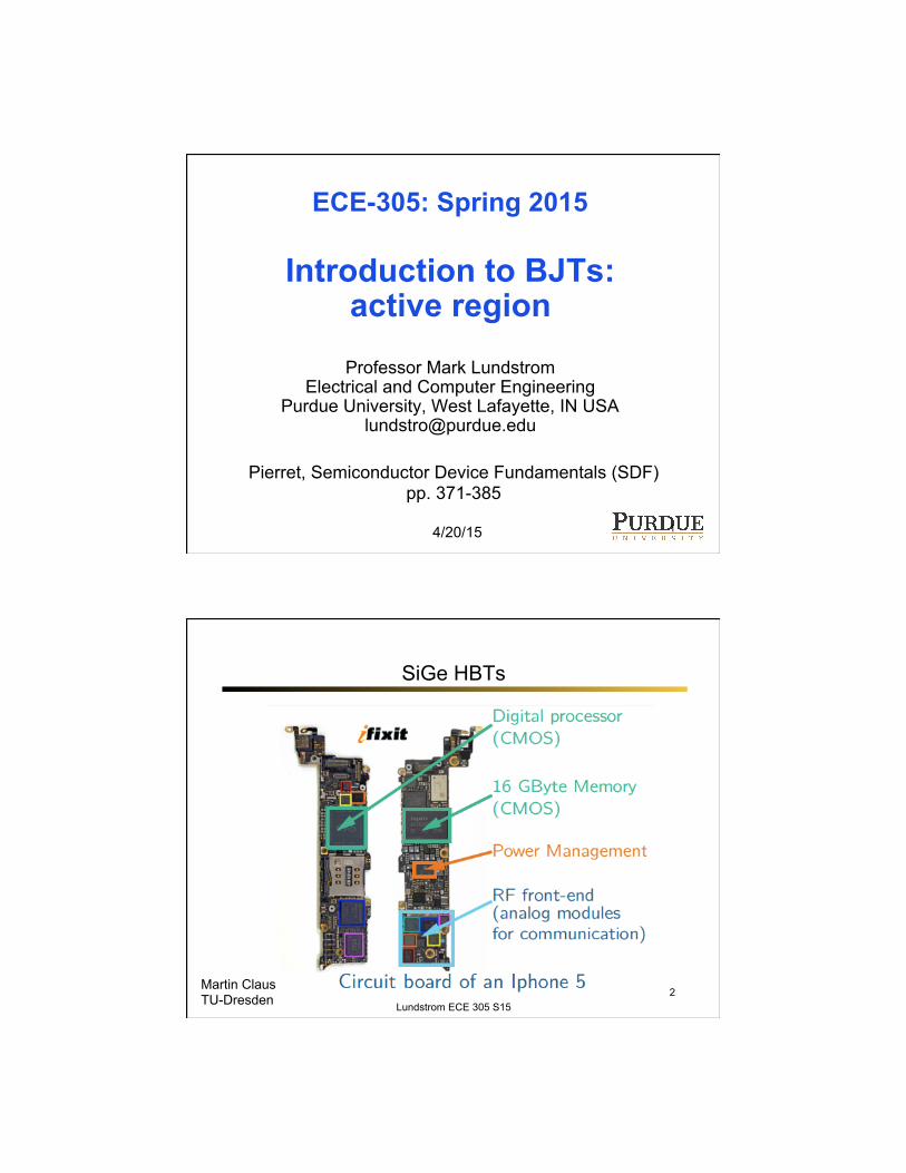
ECE-305: Spring 2015
Introduction to BJTs: active region
Professor Mark Lundstrom
Electrical and Computer Engineering Purdue University, West Lafayette, IN USA
4/20/15
Pierret, Semiconductor Device Fundamentals (SDF) pp. 371-385
1
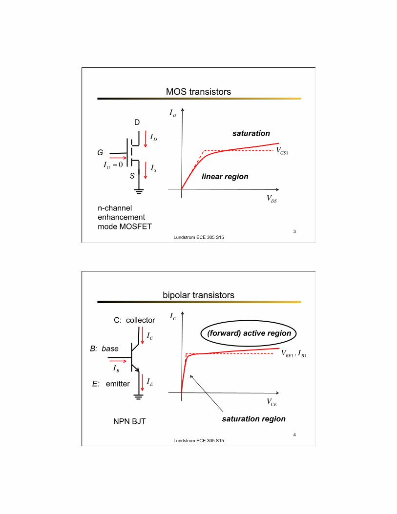
SiGe HBTs
Martin Claus TU-Dresden Lundstrom ECE 305 S15
2
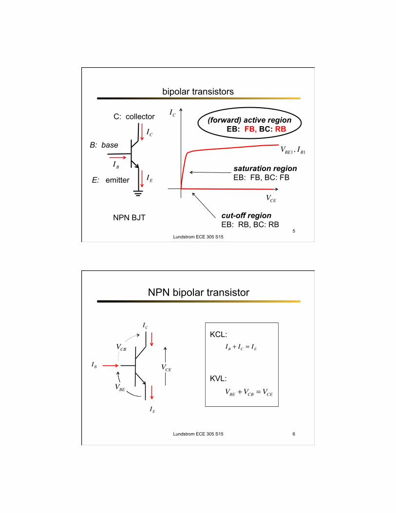
MOS transistors
Lundstrom ECE 305 S15
VDSn-channel enhancement mode MOSFET
ID
VGS1
S
D
G
ID
ISIG ≈ 0
saturation
linear region
3
bipolar transistors
Lundstrom ECE 305 S15
VCE
E: emitter
C: collector
B: base
IC
NPN BJT
IC
VBE1, IB1
IE
IB
(forward) active region
saturation region
4
bipolar transistors
Lundstrom ECE 305 S15
VCE
E: emitter
C: collector
B: base
IC
NPN BJT
IC
VBE1, IB1
IE
IB
(forward) active region EB: FB, BC: RB
saturation region EB: FB, BC: FB
cut-off region EB: RB, BC: RB
5
NPN bipolar transistor
IC
IB VCE
VBE
VCB
IE
IB + IC = IE
VBE +VCB = VCE
KCL:
KVL:
Lundstrom ECE 305 S15 6
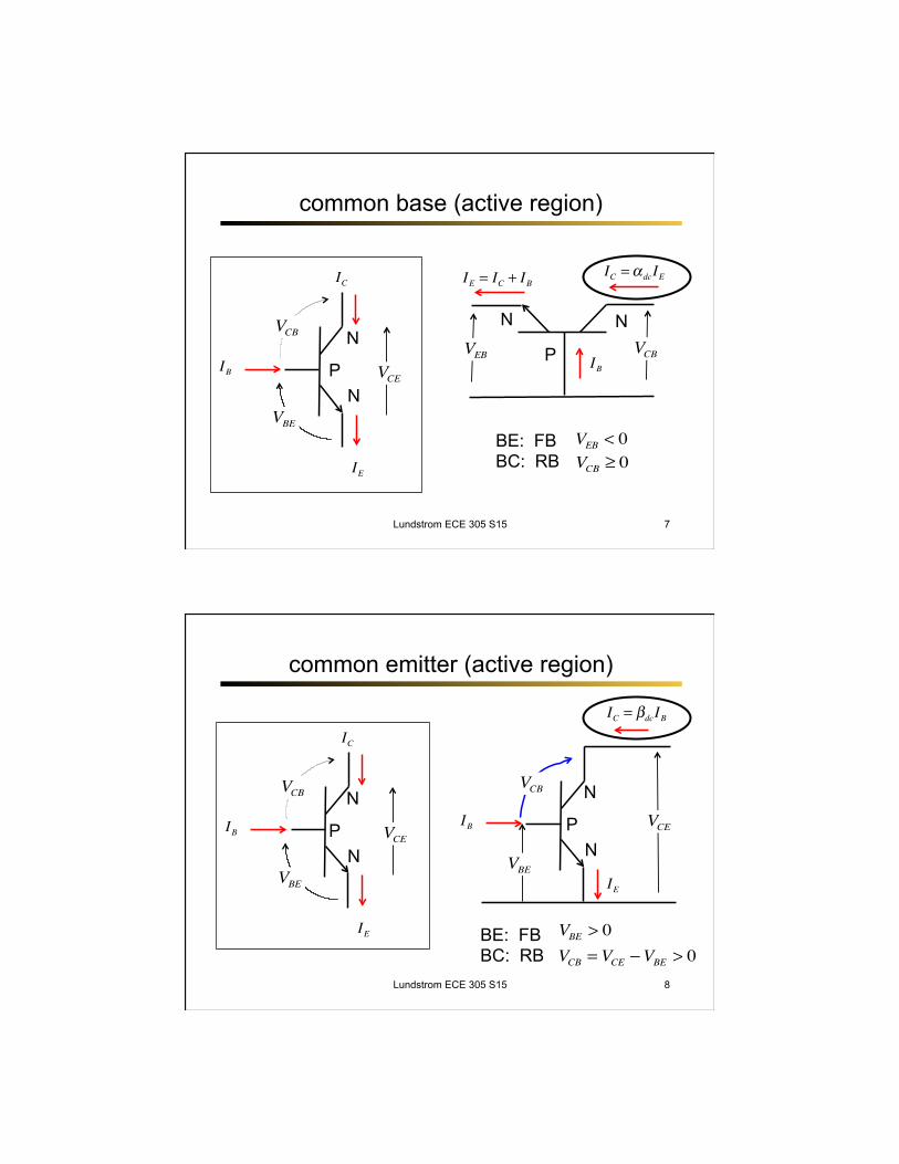
common base (active region)
IC
IB VCE
VBE
VCB
IE
N
N P
IC =α dcIE
VCBVEB IB
IE = IC + IB
BE: FB BC: RB
VEB < 0VCB ≥ 0
N N
P
Lundstrom ECE 305 S15 7
common emitter (active region)
IC
IB VCE
VBE
VCB
IE
N
N P
BE: FB BC: RB
VBE > 0VCB = VCE −VBE > 0
IB VCE
IEVBE
N
N P
VCB
Lundstrom ECE 305 S15
IC = βdcIB
8
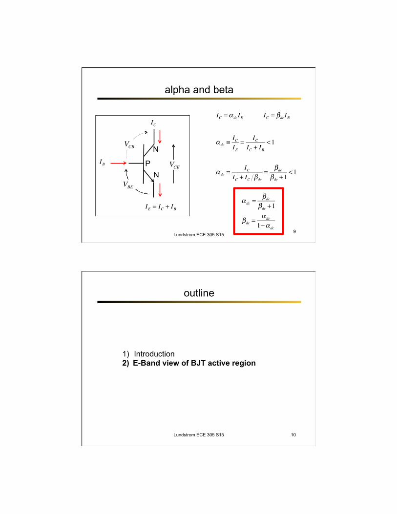
alpha and beta
Lundstrom ECE 305 S15
α dc ≡ICIE
= ICIC + IB
<1
IC
IB VCE
VBE
VCB
IE = IC + IB
N
N P
α dc =IC
IC + IC βdc
= βdc
βdc +1<1
IC = βdcIBIC =α dcIE
α dc =βdc
βdc +1
βdc =α dc
1−α dc9
outline
Lundstrom ECE 305 S15
1) Introduction 2) E-Band view of BJT active region
10
understanding MOSFETs
VGS >VT VD 0
p-Si
n-Si n-Si
y
To understand this device, we should first draw an Energy Band Diagram.
Lundstrom ECE 305 S15
x
11
how MOS transistors work
2007 N-MOSFET
(Courtesy, Shuji Ikeda, ATDF, Dec. 2007)
Lundstrom ECE 305 S15
VGS
EC
VBE VCE = 0.05 V
EC
VGS VBE
VCE = 0.6 V
12
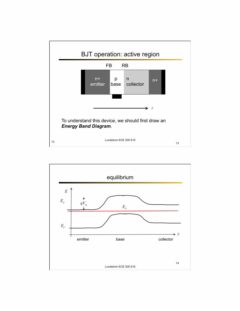
BJT operation: active region
13 13
n+ emitter
p base
n collector
n+
FB RB
y
To understand this device, we should first draw an Energy Band Diagram.
Lundstrom ECE 305 S15
equilibrium
y
EF
EC
EV
E
emitter base collector
Lundstrom ECE 305 S15
qVbi
14
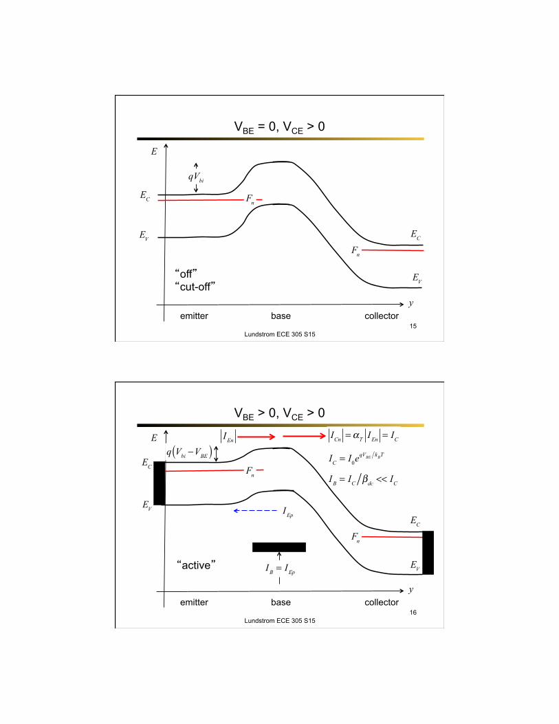
VBE = 0, VCE > 0
y
EC
EV
E
collector
Lundstrom ECE 305 S15
qVbi
15 emitter base
Fn
Fn
EC
EV“off” “cut-off”
VBE > 0, VCE > 0
y
EC
EV
E
collector
Lundstrom ECE 305 S15
q Vbi −VBE( )
16 emitter base
Fn
Fn
EC
EV“active”
IEn
ICn =αT IEn = IC
IC = I0eqVBE kBT
IEp
IB = IEp
IB = IC βdc << IC


![Securing Active Directory Administration - adsecurity.org · Securing Active Directory Administration Sean Metcalf (@Pyrotek3) s e a n [@] TrimarcSecurity.com TrimarcSecurity.com](https://img.pdfslide.us/doc/110x75/5c66758d09d3f2f91c8c4a83/securing-active-directory-administration-securing-active-directory-administration.jpg)