Embed Size (px)
Citation preview

010RZ–01
B73283
1
2
3
4
5
6
–INTRODUCTION 2004 Prius – Preliminary Release (RM1075U)01–5
5Author: Date:
2004 Prius – Preliminary Release (RM1075U)
REPAIR INSTRUCTIONPRECAUTION1. BASIC REPAIR HINT(a) HINTS ON OPERATIONS
1 LooksAlways wear a clean uniform.A hat and safety shoes must be worn.
2 Vehicle protection Prepare a grille cover, fender cover, seat cover and floor mat before starting the repairs.
3 Safe operation
When working with 2 or more persons, be sure to check safety for one another.When working with the engine running, make sure to provide ventilation for exhaust fumes in the
workshop. If working on high temperature, high pressure, rotating, moving, or vibrating parts, wear appropriate safety
equipment and take extra care not to injure yourself or others.When jacking up the vehicle, be sure to support the specified location with a safety stand.When lifting up the vehicle, use appropriate safety equipment.
4Preparation of tools andmeasuring gauge
Before starting operation, prepare a tool stand, SST, gauge, oil, shop rag and parts for replacement.
5Removal and installation,disassembly and assem-bly operations
Diagnose with a thorough understanding of proper procedures and of the reported problem.Before removing the parts, check the general condition of the assembly and for deformation and damage.When the assembly is complicated, take notes. For example, note the total number of electrical connections,
bolts, or hoses removed. Add matchmarks to insure re–assembly of components in the original positions.Temporarily mark hoses and their fittings, if needed.
Clean and wash the removed parts if necessary and assemble them after a thorough check.
6 Removed parts
Place the removed parts in a separate box to avoid mixing them up with the new parts or contaminating thenew parts.
For non–reusable parts such as a gasket, O–ring, and self–locking nut, replace them with new ones followingthe instructions in this manual.
Retain the removed parts for customer inspection, if requested.

Z11554
Seal Lock Adhesive
BE1367
Medium Current Fuse and High CurrentFuse Equal Amperage Rating
D27353D27353
V35002
Illustration Symbol Part Name Abbreviation
FUSE
MEDIUM CURRENT FUSE
HIGH CURRENT FUSE
FUSE
M–FUSE
H–FUSE
01–6–INTRODUCTION 2004 Prius – Preliminary Release (RM1075U)
6Author: Date:
2004 Prius – Preliminary Release (RM1075U)
(b) JACKING UP AND SUPPORTING VEHICLE(1) Care must be taken when jacking up and supporting the vehicle. Be sure to lift and support the
vehicle at the proper locations (see page 01–34).
(c) PRECOATED PARTS(1) Precoated parts are bolts and nuts that are coated
with a seal lock adhesive at the factory.(2) If a precoated part is retightened, loosened or
moved in anyway, it must be recoated with the spe-cified adhesive.
(3) When reusing precoated parts, clean off the oldadhesive and dry the part with compressed air.Then apply new seal lock adhesive appropriate tothe bolts and nuts.
NOTICE:Perform the torque with the lower limit value of the torquetolerance.
(4) Some seal lock agents harden slowly. You mayhave to wait for the seal lock agent to harden.
(d) GASKETS(1) When necessary, use a sealer on gaskets to prevent leaks.
(e) BOLTS, NUTS AND SCREWS(1) Carefully follow all the specifications for tightening torques. Always use a torque wrench.
(f) FUSES(1) When replacing fuses, be sure that the new fuse
has the correct amperage rating. DO NOT exceedthe rating or use one with a lower rating.
D25786
Shape (Example) Removal/Installation
Clip Remover
Pliers
Screwdriver
Scraper
Protective Tape
Clip
Protective Tape
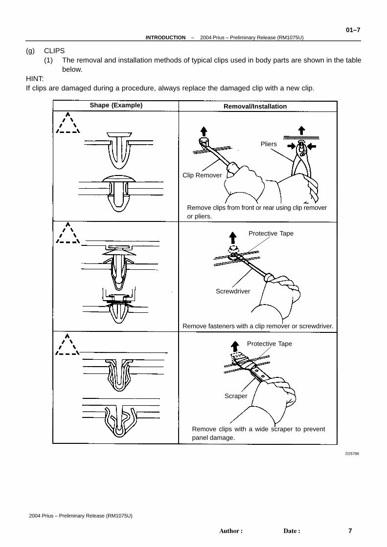
Remove clips from front or rear using clip removeror pliers.
Remove fasteners with a clip remover or screwdriver.
Remove clips with a wide scraper to preventpanel damage.
–INTRODUCTION 2004 Prius – Preliminary Release (RM1075U)01–7
7Author: Date:
2004 Prius – Preliminary Release (RM1075U)
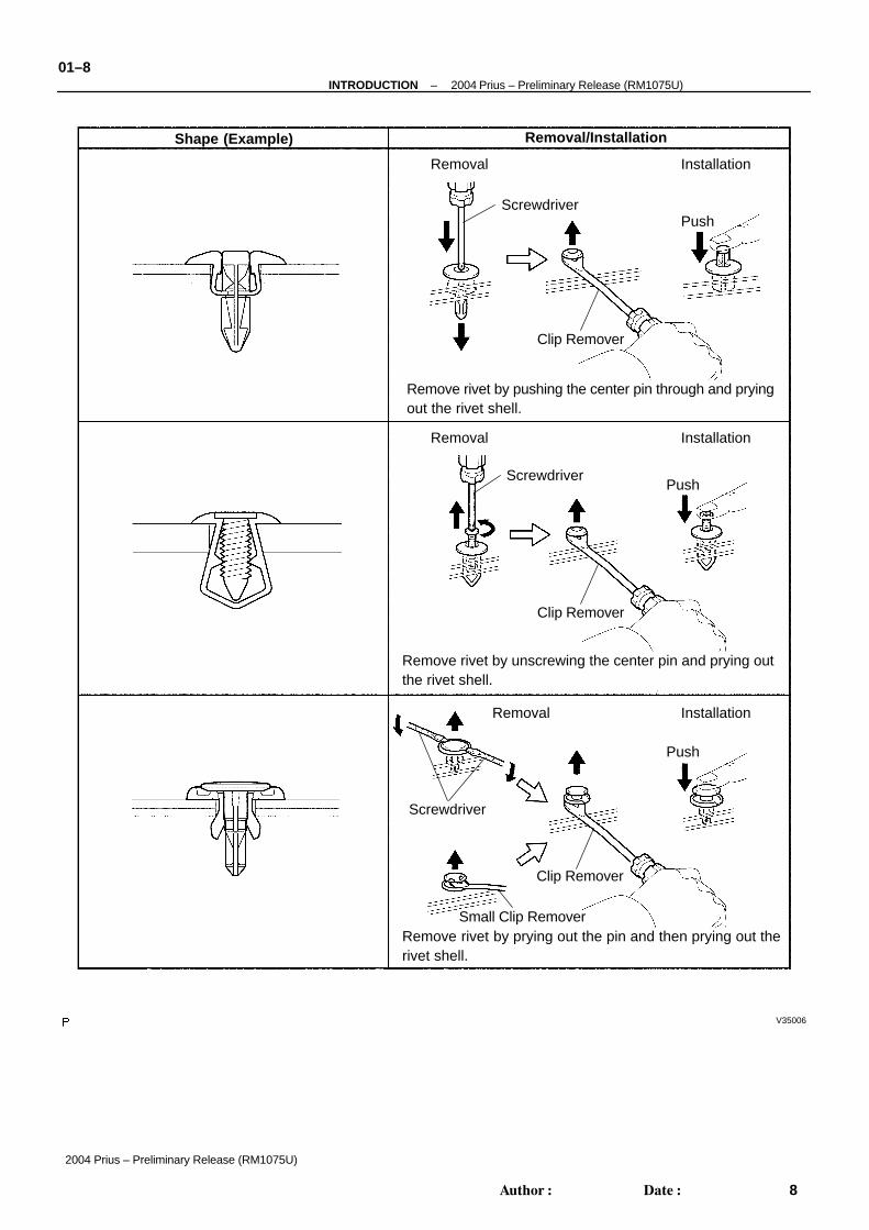
(g) CLIPS(1) The removal and installation methods of typical clips used in body parts are shown in the table
below.HINT:If clips are damaged during a procedure, always replace the damaged clip with a new clip.
V35006
Shape (Example) Removal/Installation
Removal Installation
Removal Installation
Removal Installation
Screwdriver
Screwdriver
Screwdriver
Clip Remover
Clip Remover
Clip Remover
Push
Push
Push
Small Clip Remover
Remove rivet by pushing the center pin through and pryingout the rivet shell.
Remove rivet by unscrewing the center pin and prying outthe rivet shell.
Remove rivet by prying out the pin and then prying out therivet shell.
01–8–INTRODUCTION 2004 Prius – Preliminary Release (RM1075U)
8Author: Date:
2004 Prius – Preliminary Release (RM1075U)

D31750
INCORRECT CORRECT
D25064
L1 L2L1 L2L1 L2L1 L2
D02612
L2L1 L2L1 L2L1 L2L1
D01201
–INTRODUCTION 2004 Prius – Preliminary Release (RM1075U)01–9
9Author: Date:
2004 Prius – Preliminary Release (RM1075U)
(h) REMOVAL AND INSTALLATION OF VACUUM HOSES(1) To disconnect vacuum hoses, pull and twist from
the end of the hose. Do not pull from the middle ofthe hose as this may cause damage.
(2) When disconnecting vacuum hoses, use tags toidentify where they should be reconnected.
(3) After completing the job, double check that the vac-uum hoses are properly connected. The label underthe hood shows the proper layout.
(4) When using a vacuum gauge, never force the hoseonto a connector that is too large. Use a step–downadapter for adjustment. Once a hose has beenstretched, it may leak air.
(i) TORQUE WHEN USING TORQUE WRENCH WITH EX-TENSION TOOL(1) If SST or an extension tool is combined with the
torque wrench to extend its length, do not tightenthe torque wrench to the specified torque values inthis manual. The resulting torque will be excessive.
(2) Use the formula below to calculate special torquevalues for situations where SST or an extension toolis combined with the torque wrench.
(3) Formula: T’ = T x L2/(L1 + L2)
T’ Reading of torque wrench N⋅m (kgf⋅cm, ft⋅lbf)
T Torque N⋅m (kgf⋅cm, ft⋅lbf)
L1 Length of SST or extension tool (cm)
L2 Length of torque wrench (cm)

A83545
B76060
DO NOT WEAR
D32047
01–10–INTRODUCTION 2004 Prius – Preliminary Release (RM1075U)
10Author: Date:
2004 Prius – Preliminary Release (RM1075U)
2. PRECAUTIONS FOR HIGH–VOLTAGE CIRCUIT IN-SPECTION AND SERVICE
(a) Engineer must undergo special training to be able to per-form high–voltage system inspection and servicing.
(b) All high–voltage wire harness connectors are coloredorange. The HV battery and other high–voltage compo-nents have ”High Voltage” caution labels. Do not care-lessly touch these wires and components.
(c) Before inspecting or servicing the high–voltage system,be sure to follow safety measures, such as wearing insu-lated gloves and removing the service plug to preventelectrocution. Carry the removed service plug in yourpocket to prevent other technicians from reinstalling itwhile you are servicing the vehicle.
(d) After removing the service plug, wait 5 minutes beforetouching any of the high–voltage connectors and termi-nals.
HINT:5 minutes are required to discharge the high–voltage condens-er inside the inverter.(e) Be sure to install the service plug before starting the hy-
brid system. Starting the hybrid system with the serviceplug removed may damage the vehicle.
(f) Before wearing insulated gloves, make sure that they arenot cracked, ruptured, torn, or damaged in any way. Donot wear wet insulated gloves.
(g) When servicing the vehicle, do not carry metal objects likemechanical pencils or scales that can be dropped acci-dentally and cause a short circuit.
(h) Before touching a bare high–voltage terminal, wear insu-lated gloves and use an electrical tester to ensure that theterminal is not charged with electricity (approximately 0V).
(i) After disconnecting or exposing a high–voltage connec-tor or terminal, insulate it immediately using insulationtape.
(j) The screw of a high–voltage terminal should be tightenedfirmly to the specified torque. Both insufficient and exces-sive torque can cause failure.
(k) Use the ”CAUTION: HIGH VOLTAGE. DO NOT TOUCHDURING OPERATION” sign to notify other engineers thata high–voltage system is being inspected and/or re-paired.
(l) Do not place the battery upside down while removing andinstalling it.

–INTRODUCTION 2004 Prius – Preliminary Release (RM1075U)01–11
11Author: Date:
2004 Prius – Preliminary Release (RM1075U)
(m) After servicing the high–voltage system and before rein-stalling the service plug, check again that you have notleft a part or tool inside, that the high–voltage terminalscrews are firmly tightened, and that the connectors arecorrectly connected.
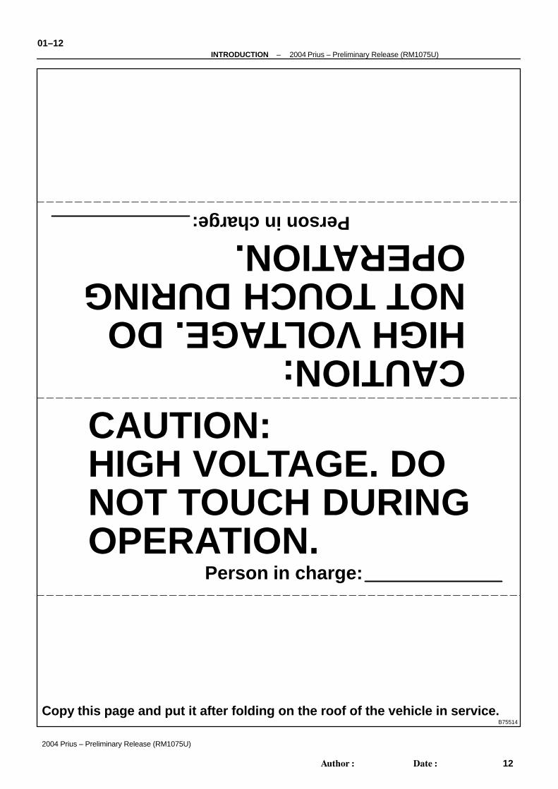
CAUTION:HIGH VOLTAGE. DONOT TOUCH DURINGOPERATION.
CAUTION:HIGH VOLTAGE. DONOT TOUCH DURINGOPERATION.
Person in charge: Person in charge:
Copy this page and put it after folding on the roof of the vehicle in service.B75514
01–12–INTRODUCTION 2004 Prius – Preliminary Release (RM1075U)
12Author: Date:
2004 Prius – Preliminary Release (RM1075U)
B75513
D31846
Inverter
Relay Block
B75501
–INTRODUCTION 2004 Prius – Preliminary Release (RM1075U)01–13
13Author: Date:
2004 Prius – Preliminary Release (RM1075U)
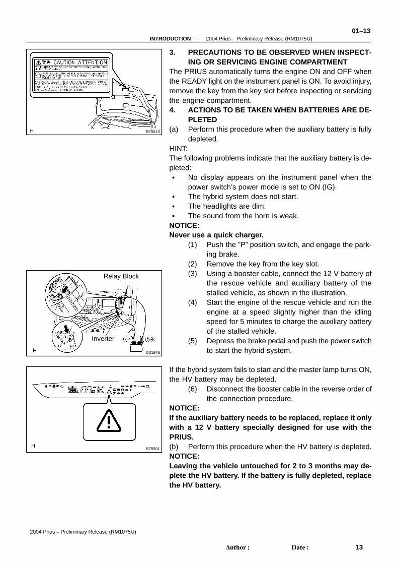
3. PRECAUTIONS TO BE OBSERVED WHEN INSPECT-ING OR SERVICING ENGINE COMPARTMENT
The PRIUS automatically turns the engine ON and OFF whenthe READY light on the instrument panel is ON. To avoid injury,remove the key from the key slot before inspecting or servicingthe engine compartment.4. ACTIONS TO BE TAKEN WHEN BATTERIES ARE DE-
PLETED(a) Perform this procedure when the auxiliary battery is fully
depleted.HINT:The following problems indicate that the auxiliary battery is de-pleted: No display appears on the instrument panel when the
power switch’s power mode is set to ON (IG). The hybrid system does not start. The headlights are dim. The sound from the horn is weak.
NOTICE:Never use a quick charger.
(1) Push the ”P” position switch, and engage the park-ing brake.
(2) Remove the key from the key slot.(3) Using a booster cable, connect the 12 V battery of
the rescue vehicle and auxiliary battery of thestalled vehicle, as shown in the illustration.
(4) Start the engine of the rescue vehicle and run theengine at a speed slightly higher than the idlingspeed for 5 minutes to charge the auxiliary batteryof the stalled vehicle.
(5) Depress the brake pedal and push the power switchto start the hybrid system.
If the hybrid system fails to start and the master lamp turns ON,the HV battery may be depleted.
(6) Disconnect the booster cable in the reverse order ofthe connection procedure.
NOTICE:If the auxiliary battery needs to be replaced, replace it onlywith a 12 V battery specially designed for use with thePRIUS.(b) Perform this procedure when the HV battery is depleted.NOTICE:Leaving the vehicle untouched for 2 to 3 months may de-plete the HV battery. If the battery is fully depleted, replacethe HV battery.
B76088
Multi Information Display:
HV System Warning
01–14–INTRODUCTION 2004 Prius – Preliminary Release (RM1075U)
14Author: Date:
2004 Prius – Preliminary Release (RM1075U)
5. INSPECTION MODEHINT: The PRIUS’ engine automatically stops if the vehicle is stopped, the engine is warmed up, the battery
is well charged, and A/C compressor operation is not being used. Activate inspection mode when con-tinuous operation of the engine is required.
The PRIUS has a motor TRAC function. When the wheel speed of the front wheels exceeds that ofrear wheels, the wheel speed of the front wheels is restrained. It is necessary to activate inspectionmode and deactivate the motor TRAC function when turning only the front wheels using a speedome-ter tester.
(a) Vehicle conditions(1) Before activating inspection mode, turn the air conditioning off, start the engine with the selector
lever in the P position, and check that the engine stops within several seconds after starting (en-gine warm up check).
(2) Activate inspection mode and inspect the vehicle. The shift position for each test is as follows:Test item Shift position Inspection mode
1. Vehicle straight travelling test
(side slip inspection)D ON or OFF
2. Breaking force test N ON or OFF
3. Speed meter test D ON
4. Exhaust gas test (idling) P ON
5. Headlight test P ON or OFF
(3) Reset inspection mode immediately after completion of inspection.NOTICE:Driving the vehicle without resetting inspection mode may damage the transaxle.(b) Special notes for speedometer testNOTICE:Do not use the speedmeter tester to perform rapid starting or quick accleration/deceleration withoutfirst setting the proper load on the vehicle. Failing to set the load may damage the transaxle.
(1) Depress the accelerator pedal slowly and gradually accelerate the vehicle. Make a measure-ment.
(2) After the measurement, use the brake to gradually decelerate the vehicle.(c) Special note for using the chassis dynamometer
Always set an appropriate load before starting the test.
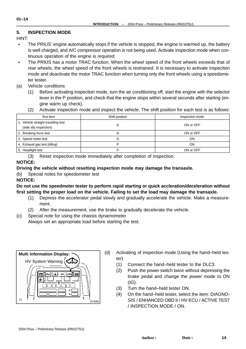
(d) Activating of inspection mode (Using the hand–held tes-ter)(1) Connect the hand–held tester to the DLC3.(2) Push the power switch twice without depressing the
brake pedal and change the power mode to ON(IG).
(3) Turn the hand–held tester ON.(4) On the hand–held tester, select the item: DIAGNO-
SIS / ENHANCED OBD II / HV ECU / ACTIVE TEST/ INSPECTION MODE / ON.

A82837
–INTRODUCTION 2004 Prius – Preliminary Release (RM1075U)01–15
15Author: Date:
2004 Prius – Preliminary Release (RM1075U)
(5) Activate inspection mode. Check that the HV sys-tem warning on the multi–information display startsblinking and master warning lamp on the combina-tion meter is illuminated.
(6) Depress and hold the brake pedal, and then pushthe power switch. The vehicle’s engine should runcontinuously without stopping.
(e) Deactivating inspection mode(1) Change the power switch’s power mode to OFF. In-
spection mode and the main system (HV system)are turned off simultaneously.
NOTICE: The idle speed in inspection mode is approximately
1,000 rpm. The number of revolutions will increase to:1) 1,500 rpm if the accelerator pedal is less than 60 %depressed, and 2) 2,500 rpm if the pedal is more than60% depressed.
If a diagnosis code is recorded when entering inspec-tion mode, the master lamp and the error warninglamp on the multi–center display are illuminated.
When the master warning light is illuminated duringoperation in inspection mode, deactivate inspectionmode and inspect the diagnosed area.
Traveling on a road without r esetting inspectionmode may damage the transaxle.
HINT:Depress and hold the brake pedal, and then push the power switch. The vehicle’s engine should run continu-ously without stopping.6. ACTIONS TO BE TAKEN FOR VEHICLE DAMAGED BY IMPACT(a) Items to be prepared or operation at the site of the accident
Protective clothing (insulated gloves, rubber gloves, goggles, and safety shoes) Saturated boric acid solution 20 L (obtain 800 g of boric acid powder, put it into a container, and
dissolve it in water) Red litmus paper ABC fire extinguisher (effective against both oil flames and electrical flames) Shop rags (for wiping off the electrolyte) Vinyl tape (for insulating cable) Electrical tester
(b) Actions to be taken at the place of accident(1) Wear insulated or rubber gloves, goggles and safety shoes.(2) Do not touch a bare cable that could be a high voltage cable. If the cable must be touched or
if accidental contact is unavoidable, follow these instructions: 1) wear insulated or rubber glovesand goggles, 2) measure the voltage between the cable and the body ground using an electricaltester, and 3) insulate the cable using vinyl tape.
(3) If the vehicle catches on fire, use an ABC fire extinguisher to extinguish the fire. Trying to extin-guish a fire using only a small amount of water can be more dangerous than effective. Use a sub-stantial amount of water or wait for firefighters.

B76085
High–voltage Part and Wiring
Inverter and Converter
HV Battery
Power Cable
Hybrid Transaxle
A/C Compressor
01–16–INTRODUCTION 2004 Prius – Preliminary Release (RM1075U)
16Author: Date:
2004 Prius – Preliminary Release (RM1075U)
(4) Visually check the HV battery and immediate area for any electrolyte leakage. Do not touch anyleaked liquid because it could be highly alkaline electrolyte. Wear rubber gloves and goggles,and then apply red litmus paper to the leak. If the paper turns blue, the liquid must be neutralizedbefore wiping. Neutralize the liquid using the following procedures:1) apply saturated boric acid solution to the liquid, and 2) reapply red litmus paper and make sureit does not turn blue. Repeat steps 1 and 2 above until the paper does not turn blue. Then, wipethe neutralized liquid with a shop rag.
(5) If damage to any of the high–voltage components and cables is suspected, cut the high–voltagecircuit using the procedure on the following pages.
Push the ”P” position switch and engage the park-ing brake.
Remove the key from the key slot. Then disconnectthe negative (–) terminal of the auxiliary battery.

B75497
Service Plug
B74192B74191 B76062
Engine Room J/B
Power Integration
HV Fuse
B75503
–INTRODUCTION 2004 Prius – Preliminary Release (RM1075U)01–17
17Author: Date:
2004 Prius – Preliminary Release (RM1075U)
Remove the service plug while wearing insulatedgloves.
Do not turn the power switch on while removing theservice plug.
If the service plug cannot be removed due to dam-age to the rear portion of the vehicle, remove the HVfuse or power integration (IGCT Relay) instead.
(c) Moving the damaged vehicleHINT:If any of the following applies, tow the vehicle away using a towtruck. One or more of the high–voltage components and cables
are damaged. The driving, traction, or fuel system is damaged.
The READY lamp is not illuminated when you turn.NOTICE: Before tow ing the vehicle away using a tow truck, dis-
connect the cable from the negative (–) terminal of theauxiliary battery and remove the service plug.Only if none of the above applies and there are noproblems that might affect driving, drive the vehicleaway from the place of accident to a safe, nearbyplace.
Perform the procedure below if the READY lamp turnsoff, or there are abnormal noises, unusual smells, orstrong vibrations while driving:(1) Park the vehicle in a safe place.(2) Push the ”P” position switch and engage the park-
ing brake.(3) Disconnect the power cable from the negative (–)
terminal of the auxiliary battery.(4) Remove the service plug while wearing insulated
gloves.

01–18–INTRODUCTION 2004 Prius – Preliminary Release (RM1075U)
18Author: Date:
2004 Prius – Preliminary Release (RM1075U)
(d) Actions required after moving the damaged vehicleIf you see any liquid on the road surface, it could be highlyalkaline electrolyte leakage.Wear rubber gloves and goggles, and apply red litmus pa-per to the leak. If the paper turns blue, the liquid must beneutralized before wiping. Neutralize the liquid using thefollowing procedures: 1) apply saturated boric acid solu-tion to the liquid, and 2) red litmus paper and make sureit does not turn blue. Repeat steps 1 and 2 above until thepaper does not turn blue. Then wipe the neutralized liquidwith a shop rag.
(e) Items to be prepared (when repairing damaged vehicles) Protective clothing (Insulated gloves, rubber
gloves, goggles, and safety shoes) Saturated boric acid solution 20 L (obtain 800 g of
boric acid powder, put it into a container, and dis-solve it in water)
Red litmus paper Shop rags (for wiping off the electrolyte) Vinyl tape (for insulating cable) Electrical tester
(f) Precautions to be observed when servicing the damagedvehicle(1) Wear insulated or rubber gloves, goggles, and safe-
ty shoes.(2) Do not touch a bare cable that could be a high volt-
age cable. If the cable must be touched or if acci-dental contact is unavailable, follow these instruc-tions: 1) wear insulated or rubber gloves andgoggles, 2) measure the voltage between the cableand the body ground using an electrical tester, and3) insulate the cable using vinyl tape.
(3) Check the HV battery and immediate area for anyelectrolyte leakage. Do not touch any leaked liquidbecause it could be highly alkaline electrolyte. Wearrubber gloves and goggles, and then apply red lit-mus paper to the leak. If the paper turns blue, theliquid must be neutralized before wiping. Neutralizethe liquid using the following procedures:1) apply saturated boric acid solution to the liquid,and 2) reapply red litmus paper and make sure itdoes not turn blue. Repeat steps 1 and 2 above untilthe paper does not turn blue, Then wipe the neutral-ized liquid with a shop rag.
(4) If the electrolyte adheres to your skin, wash the skinimmediately using saturated boric acid solution ora large amount of water. If the electrolyte adheresto an article of clothing, take it off immediately.

B76063
–INTRODUCTION 2004 Prius – Preliminary Release (RM1075U)01–19
19Author: Date:
2004 Prius – Preliminary Release (RM1075U)
(5) If the electrolyte comes in contact with your eyes,call out loudly for help. Do not rub your eyes. Washthem with a large amount of water and seek medicalcare immediately.
(6) If damage to any of the high–voltage componentsand cables is suspected, cut the high–voltage cir-cuit using the procedure below. Push the ”P” position switch and engage the
parking brake. Remove the key from the key slot. Then dis-
connect the power cable from the negative(–) terminal of the auxiliary battery.
Wear insulated gloves, and then remove theservice plug.
If you cannot remove the service plug due todamage to the rear portion of the vehicle, re-move the HV fuse or IGCT relay instead.
(g) Precautions to be taken when disposing of the vehicleWhen scrapping the vehicle, remove the HV battery fromthe vehicle and return it to the location specified by themanufacturer. The same applies to any damaged HV bat-tery.
(h) After removing the battery, keep it away from water. Watermay heat the battery, which results in fire.
(i) Precautions to be observed when towingTow the damaged vehicle with its front wheels or its frontand rear wheels lifted off the ground.
NOTICE:Towing the damaged vehicle with its front wheels on theground may cause the motor to generate electricity. Thiselectricity could, depending on the nature of the damage,leak and cause a fire.(j) Towing with 4 wheels on the groundNOTICE: If the damaged vehicle needs to be towed using a
rope, do not exceed 30 km/h and tow only for veryshort distances. Foe example, towing from the acci-dent site to a nearby tow truck is permissible.
Change the power switch’s power mode to ON (IG)and shift the selector lever to the N position.
If any abnormality is present in the damaged vehicleduring towing, stop towing immediately.
(k) Towing eyelet(1) Install the hook.(2) Hook a rope on to the illustrated area for towing.

01–20–INTRODUCTION 2004 Prius – Preliminary Release (RM1075U)
20Author: Date:
2004 Prius – Preliminary Release (RM1075U)
7. FOR VEHICLES EQUIPPED WITH SRS AIRBAG AND SEAT BELT PRETENSIONERHINT:The PRIUS is equipped with a Supplemental Restraint System (SRS) and seat belt pretensioner.Failure to carry out the service operations in the correct sequence could cause the SRS to unexpectedlydeploy during servicing and lead to serious injury.Furthermore, if a mistake is made when servicing the SRS, it is possible that the SRS may fail to operateproperly. Before servicing (including removal or installation of parts, inspection or replacement), be sure toread the following section carefully.(a) GENERAL NOTICE
(1) As the malfunction symptoms of the SRS are difficult to confirm the Diagnostic Trouble Codes(DTCs) become the most important source of information when troubleshooting. When trouble-shooting the SRS, always check the DTCs before disconnecting the battery (see page 05–1402).
(2) Work must be started at least 90 seconds after the ignition switch is turned to the LOCK positionand the negative (–) terminal cable is disconnected from the battery.(The SRS is equipped with a back–up power source. If work is started within 90 seconds afterturning the ignition switch to lock and disconnecting the negative (–) terminal cable from the bat-tery, the SRS may deploy).When the negative (–) terminal cable is disconnected from the battery, clock and audio systemmemory is erased. Before starting work, make a note of the settings of each memory system.When work is finished, reset the clock and audio systems as before.
CAUTION:Never use the back–up power source (battery or other) to try to keep the system memory from beingerased. The back–up power source may inadvertently power the SRS, and cause it to deploy.
(3) In minor collisions where the SRS does not deploy, the horn button assembly, instrument panelpassenger airbag assembly, front seat airbag assembly, curtain shield airbag assembly and seatbelt pretensioner should be inspected before further use of the vehicle (see pages 60–22, 60–34,60–43, 60–48 and 61–11).
(4) Never use SRS parts from another vehicle. When replacing parts, use new parts.(5) Before repairs, remove the airbag sensor if impacts are likely to be applied to the sensor during
repairs.(6) Never disassemble and repair the airbag sensor assembly, horn button assembly, instrument
panel passenger airbag assembly, front seat airbag assembly, curtain shield airbag assemblyor seat belt pretensioner.
(7) Replace the center airbag sensor assembly, side airbag sensor assembly, horn button assemblyor the instrument panel passenger airbag assembly, front seat airbag assembly or curtain shieldairbag assembly if: 1) damage has occurred from being dropped, or 2) cracks, dents or otherdefects in the case, bracket or connector are present.
(8) Do not directly expose the airbag sensor assembly, horn button assembly, instrument panel pas-senger airbag assembly, front seat airbag assembly, curtain shield airbag assembly or seat beltpretensioner to hot air or flames.
(9) Use a voltmeter/ohmmeter with high impedance (10 kΩ/V minimum) for troubleshooting electri-cal circuits.
(10) Information labels are attached to the SRS components. Follow the instructions on the labels.(11) After work on the SRS is completed, check the SRS warning lamp (see page 05–1397).

D30401
Mark
D25096
Example:
CORRECT INCORRECT
Z13950
Example:
NEVER USE AN OHMMETER ON AN AIRBAG OR PRETENSIONER
–INTRODUCTION 2004 Prius – Preliminary Release (RM1075U)01–21
21Author: Date:
2004 Prius – Preliminary Release (RM1075U)
(b) SPIRAL CABLE (in Combination Switch)(1) The steering wheel must be fitted correctly to the
steering column with the spiral cable in the neutralposition, otherwise cable disconnection and otherproblems may occur. Refer to page 60–29 for in-formation about correct installation of the steeringwheel.
(c) HORN BUTTON ASSEMBLY (with Airbag)(1) When removing the horn button assembly or handling a new horn button, it should be placed with
the pad surface facing up. See the illustration below.Placing the horn button with the pad surface facing down may lead to a serious accident if theairbag accidently inflates. Also, do not place anything on top of the horn button.
(2) Never measure the resistance of the airbag squib. This may cause the airbag to inflate, whichcould cause serious injury.
(3) Grease or detergents of any kind should not be applied to the steering wheel pad.(4) Store the horn button assembly in an area where the ambient temperature is below 93°C
(200°F), the humidity is not high and electrical noise is not nearby.(5) When using electric welding anywhere on the vehicle, disconnect the airbag sensor (ECU) con-
nectors (4 pins). These connectors contain shorting springs. This feature reduces the possibilityof the airbag or seat belt pretensioner deploying due to currents entering the squib wiring.
(6) When disposing of the vehicle or the horn button assembly by itself, the airbag should be inflatedusing an SST before disposal (see page 60–22). Perform the operation in a safe place away fromelectrical noise.

D27522
Example: CORRECT INCORRECT
Z13951
Example:
NEVER USE AN OHMMETER ON AN AIRBAG OR PRETENSIONER
01–22–INTRODUCTION 2004 Prius – Preliminary Release (RM1075U)
22Author: Date:
2004 Prius – Preliminary Release (RM1075U)
(d) INSTRUMENT PANEL PASSENGER AIRBAG ASSY(1) Always place a removed or new instrument panel passenger airbag assembly with the airbag
inflation direction facing upward.Placing the airbag assembly with the airbag inflation direction facing downward could cause aserious accident if the airbag inflates.
(2) Never measure the resistance of the airbag squib. This may cause the airbag to inflate, whichcould cause serious injury.
(3) Grease or detergents of any kind should not be applied to the instrument panel passenger airbagassembly.
(4) Store the airbag assembly in an area where the ambient temperature is below 93°C (200°F),the humidity is not high and electrical noise is not nearby.
(5) When using electric welding anywhere on the vehicle, disconnect the airbag ECU connectors(4 pins). These connectors contain shorting springs. This feature reduces the possibility of theairbag deploying due to currents entering the squib wiring.
(6) When disposing of a vehicle or the airbag assembly unit by itself, the airbag should be deployedusing SST before disposal (see page 60–34).Activate in a safe place away from electrical noise.
(e) CURTAIN SHIELD AIRBAG ASSEMBLY(1) Always place the removed or new curtain shield airbag assembly in a clear plastic bag, and keep
it in a safe place.NOTICE:Plastic bag is not re–useable.CAUTION:Never disassemble the curtain shield airbag assembly.
(2) Never measure the resistance of the airbag squib. This may cause the airbag to inflate, whichcould cause serious injury.
(3) Grease or detergents of any kind should not be applied to the curtain shield airbag assembly.

D31641
Example:
CORRECT INCORRECT
Clear Plastic Bag
D30931NEVER USE AN OHMMETER ON AN AIRBAG OR PRETENSIONER
–INTRODUCTION 2004 Prius – Preliminary Release (RM1075U)01–23
23Author: Date:
2004 Prius – Preliminary Release (RM1075U)
(4) Store the airbag assembly in an area where the ambient temperature is below 93°C (200°F),the humidity is not high and electrical noise is not nearby.
(5) When using electric welding anywhere on the vehicle, disconnect the airbag sensor (ECU) con-nectors (2 pins). These connectors contain shorting springs. This feature reduces the possibilityof the airbag deploying due to currents entering the squib wiring.
(6) When disposing of a vehicle or the curtain shield airbag assembly unit by itself, the airbag shouldbe deployed using SST before disposal (see page 60–43).Activate in a safe place away from electrical noise.
(f) FRONT SEAT AIRBAG ASSEMBLY(1) Always place a removed or new front seat airbag assembly with the airbag inflation direction fac-
ing up.Placing the airbag assembly with the airbag inflation direction facing downward could cause aserious accident if the airbag deploys.
(2) Never measure the resistance of the airbag squib. This may cause the airbag to inflate, whichcould cause serious injury.
(3) Grease should not be applied to the front seat airbag assembly, and the airbag door should notbe cleaned with detergents of any kind.
(4) Store the airbag assembly in an area where the ambient temperature is below 93°C (200°F),the humidity is not high and electrical noise is not nearby.
(5) When using electric welding anywhere on the vehicle, disconnect the airbag ECU connectors(2 pins). These connectors contain shorting springs. This feature reduces the possibility of theairbag deploying due to currents entering the squib wiring.
(6) When disposing of a vehicle or the airbag assembly unit by itself, the airbag should be deployedusing SST before disposal (see page 60–48).Activate in a safe place away from electrical noise.

D30924
Example:
NEVER USE AN OHMMETER ON AN AIRBAG OR PRETENSIONER
D30370
Example:
NEVER USE AN OHMMETER ON AN AIRBAG OR PRETENSIONER
01–24–INTRODUCTION 2004 Prius – Preliminary Release (RM1075U)
24Author: Date:
2004 Prius – Preliminary Release (RM1075U)
(g) SEAT BELT PRETENSIONER(1) Never measure the resistance of the seat belt pretensioner. This may cause the seat belt preten-
sioner to activate, which could cause serious injury.(2) Never disassemble the seat belt pretensioner.(3) Never install the seat belt pretensioner on another vehicle.(4) Store the seat belt pretensioner in an area where the ambient temperature is below 80°C
(176°F), the humidity is not high and electrical noise is not nearby.(5) When using electric welding anywhere on the vehicle, disconnect the airbag sensor (ECU) con-
nectors (2 pins). These connectors contain shorting springs. This feature reduces the possibilityof the airbag deploying due to currents entering the squib wiring.
(6) When disposing of a vehicle or the seat belt pretensioner unit by itself, the seat belt pretensionershould be activated before disposal (see page 61–11). Activate in a safe place away from electri-cal noise.
(7) As the seat belt pretensioner is hot after being activated, allow some time for it to cool down suffi-ciently before disposal. Never apply water to try to cool down the seat belt pretensioner.
(8) Grease, detergents, oil or water should not be applied to the front seat outer belt.
(h) AIRBAG SENSOR ASSEMBLY (ECU)(1) Never reuse an airbag sensor assembly that has been involved in a collision where the SRS has
deployed.(2) The connectors to the airbag sensor assembly should be connected or disconnected with the
sensor mounted on the floor. If the connectors are connected or disconnected while the airbagsensor assembly is not mounted to the floor, the SRS may activate.
(3) Work must be started at least 90 seconds after the power switch’s power mode is changed toOFF and the negative (–) terminal cable is disconnected from the battery, even if only looseningthe set bolts of the airbag sensor assembly.
(i) WIRE HARNESS AND CONNECTOR(1) The SRS wire harness is integrated with the instrument panel wire harness assembly. All the con-
nectors in the system are a standard yellow color. If the SRS wire harness becomes discon-nected or the connector becomes broken, repair or replace it.
D25080
Negative (–) Terminal
D31751
INCORRECT
–INTRODUCTION 2004 Prius – Preliminary Release (RM1075U)01–25
25Author: Date:
2004 Prius – Preliminary Release (RM1075U)
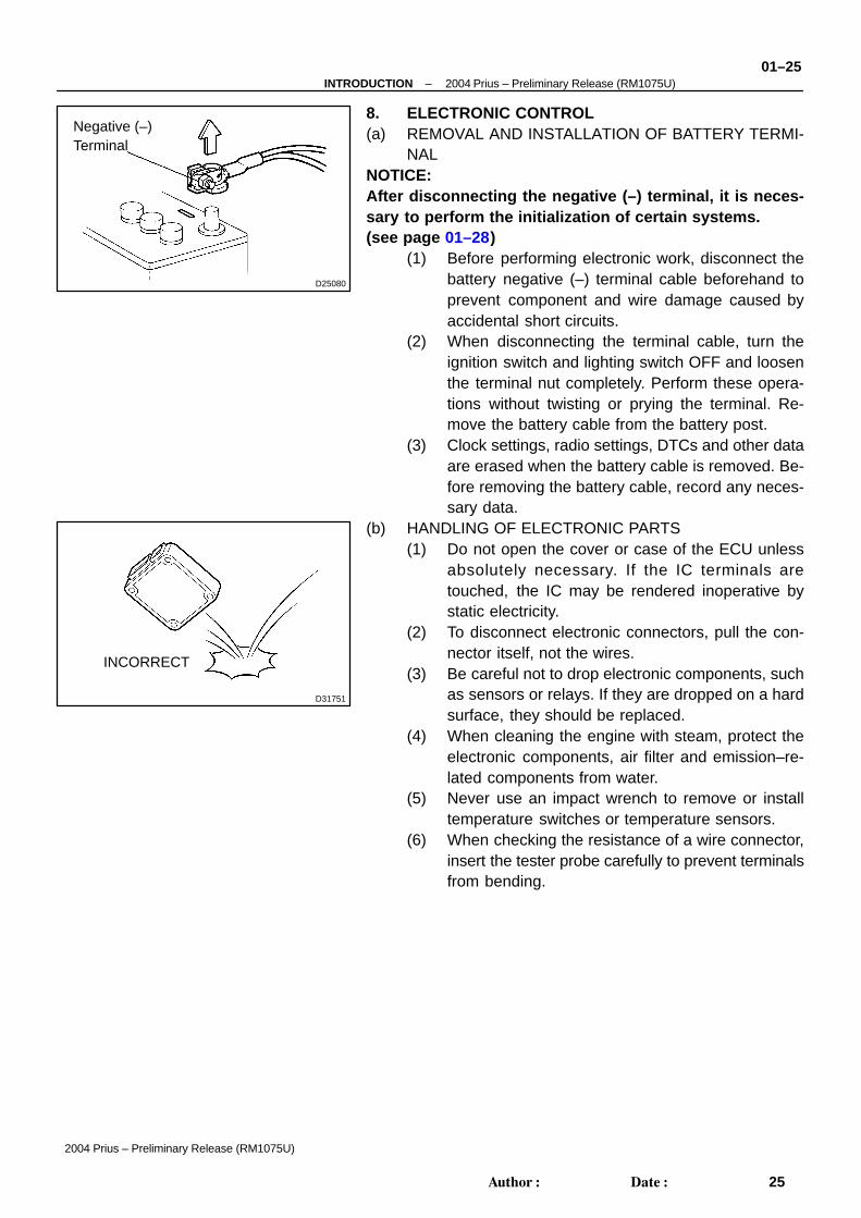
8. ELECTRONIC CONTROL(a) REMOVAL AND INSTALLATION OF BATTERY TERMI-
NALNOTICE:After disconnecting the negative (–) terminal, it is neces-sary to perform the initialization of certain systems.(see page 01–28)
(1) Before performing electronic work, disconnect thebattery negative (–) terminal cable beforehand toprevent component and wire damage caused byaccidental short circuits.
(2) When disconnecting the terminal cable, turn theignition switch and lighting switch OFF and loosenthe terminal nut completely. Perform these opera-tions without twisting or prying the terminal. Re-move the battery cable from the battery post.
(3) Clock settings, radio settings, DTCs and other dataare erased when the battery cable is removed. Be-fore removing the battery cable, record any neces-sary data.
(b) HANDLING OF ELECTRONIC PARTS(1) Do not open the cover or case of the ECU unless
absolutely necessary. If the IC terminals aretouched, the IC may be rendered inoperative bystatic electricity.
(2) To disconnect electronic connectors, pull the con-nector itself, not the wires.
(3) Be careful not to drop electronic components, suchas sensors or relays. If they are dropped on a hardsurface, they should be replaced.
(4) When cleaning the engine with steam, protect theelectronic components, air filter and emission–re-lated components from water.
(5) Never use an impact wrench to remove or installtemperature switches or temperature sensors.
(6) When checking the resistance of a wire connector,insert the tester probe carefully to prevent terminalsfrom bending.

D01563
D25081
Spring Type Clamp
Clamp Track
D20025
01–26–INTRODUCTION 2004 Prius – Preliminary Release (RM1075U)
26Author: Date:
2004 Prius – Preliminary Release (RM1075U)
9. REMOVAL AND INSTALLATION OF FUEL CONTROL PARTS(a) PLACE FOR REMOVING AND INSTALLING OF FUEL SYSTEM PARTS
(1) Work in a place with good air ventilation that does not have welders, grinders, drills, electric mo-tors, stoves, or any other ignition sources.
(2) Never work in a pit or near a pit as vaporized fuel will collect in those places.(b) REMOVING AND INSTALLING OF FUEL SYSTEM PARTS
(1) Prepare a fire extinguisher before starting operation.(2) To prevent static electricity, install a ground on the fuel changer, vehicle and fuel tank, and do
not spray the area with water. The work surface will become slippery. Do not clean up spills withwater as this will spread and gasoline and create a fire hazard.
(3) Avoid using electric motors, working lights and other electric equipment that can cause sparksor high temperatures.
(4) Avoid using iron hammers as they may create speaks.(5) Dispose of fuel–contaminated shop rags separately using a fire resistant container.
10. REMOVAL AND INSTALLATION OF ENGINE INTAKEPARTS
(a) If any metal particle enters the inlet pass, this may dam-age the engine.
(b) When removing and installing the inlet system parts, cov-er the openings of the removed parts and engine open-ings. Use clean shop rags, gummed tape, or other suit-able materials.
(c) When installing the inlet system parts, check that no metalparticles have entered the engine or the installed part.
11. HANDLING OF HOSE CLAMPS(a) Before removing the hose, check the clamp position so
that it can be reinstalled in the same position.(b) Replace deformed or dented clamps with a new one.(c) When reusing a hose, attach the clamp on the clamp track
portion of the hose.(d) For a spring type clamp, you may want to spread the tabs
slightly after installation by pushing in the direction of thearrow marks as shown in the illustration.
12. FOR VEHICLES EQUIPPED WITH MOBILE COMMU-NICATION SYSTEMS
(a) Install the antenna as far away from the ECU and sensorsof the vehicle electronic systems as possible.
(b) Install an antenna feeder at least 20 cm (7.87 in.) awayfrom the ECU and sensors of the vehicle electronic sys-tems. For details of the ECU and sensors locations, referto the section on applicable components.
(c) Keep the antenna and feeder separate from other wiringsas much as possible. This will prevent signals from thecommunication equipment from affecting vehicle equip-ment and vice–versa.
(d) Check that the antenna and feeder are correctly adjusted.(e) Do not install high–powered mobile communication sys-
tems.
A82779
DLC3
1314 15161211109
1 2 3 4 5 6 7 8
TS
CG
–INTRODUCTION 2004 Prius – Preliminary Release (RM1075U)01–27
27Author: Date:
2004 Prius – Preliminary Release (RM1075U)
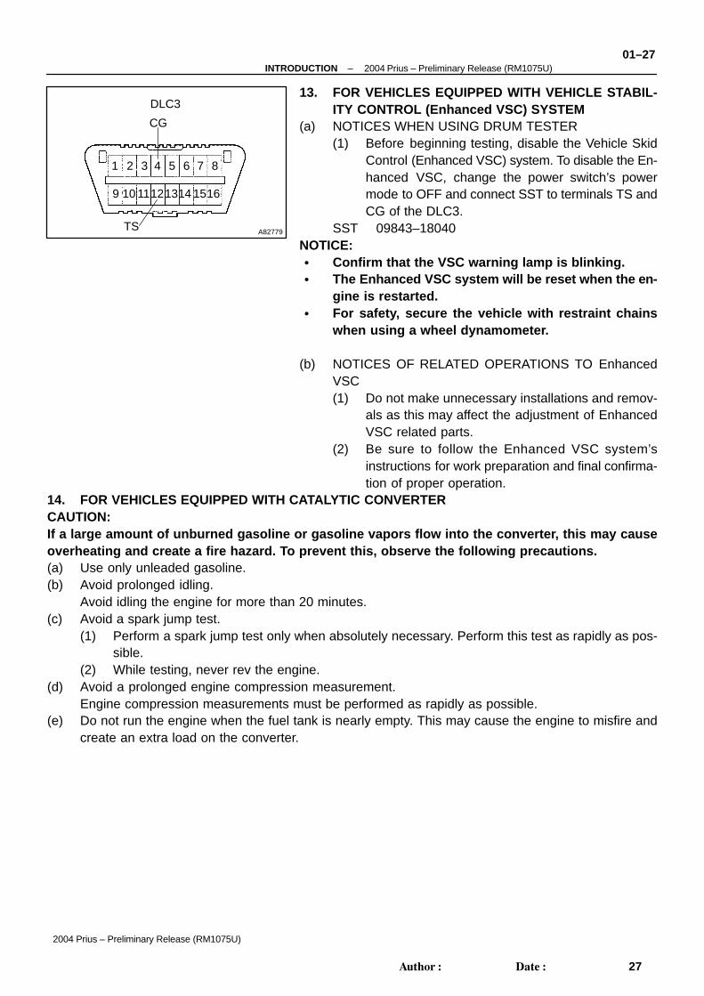
13. FOR VEHICLES EQUIPPED WITH VEHICLE STABIL-ITY CONTROL (Enhanced VSC) SYSTEM
(a) NOTICES WHEN USING DRUM TESTER(1) Before beginning testing, disable the Vehicle Skid
Control (Enhanced VSC) system. To disable the En-hanced VSC, change the power switch’s powermode to OFF and connect SST to terminals TS andCG of the DLC3.
SST 09843–18040NOTICE: Confirm that the VSC warning lamp is blinking. The Enhanced VSC system will be reset when the en-
gine is restarted. For safety, secure the vehicle with restraint chains
when using a wheel dynamometer.
(b) NOTICES OF RELATED OPERATIONS TO EnhancedVSC(1) Do not make unnecessary installations and remov-
als as this may affect the adjustment of EnhancedVSC related parts.
(2) Be sure to follow the Enhanced VSC system’sinstructions for work preparation and final confirma-tion of proper operation.
14. FOR VEHICLES EQUIPPED WITH CATALYTIC CONVERTERCAUTION:If a large amount of unburned gasoline or gasoline vapors flow into the converter, this may causeoverheating and create a fire hazard. To prevent this, observe the following precautions.(a) Use only unleaded gasoline.(b) Avoid prolonged idling.
Avoid idling the engine for more than 20 minutes.(c) Avoid a spark jump test.
(1) Perform a spark jump test only when absolutely necessary. Perform this test as rapidly as pos-sible.
(2) While testing, never rev the engine.(d) Avoid a prolonged engine compression measurement.
Engine compression measurements must be performed as rapidly as possible.(e) Do not run the engine when the fuel tank is nearly empty. This may cause the engine to misfire and
create an extra load on the converter.