Embed Size (px)
Citation preview

www.ACODrain.us
ACO DRAIN
Slab Solutions SectionSlabDrain/FG200
Introduction Pgs 1-13Selecting the right product
KlassikDrain Pgs 14-33, 54-61General purpose trench drainPart 1 - K100, K50 & Bricklslot
KlassikDrain Pgs 34-53General purpose trench drainPart 2 - K200/K300
PowerDrain Pgs 62-95Heavy duty trench drain
Slab Solutions Pgs 96-123Trench drain for concrete slabs
Design Serices & Support Pgs 124-159
ACO DRAIN
www.ACODrain.us
111
ACO DRAIN
Note: This electronic file is part of a larger 160 page Technical Handbook. Please contact ACO at 1-800-543-4764 for a copy.

SlabDrain ................... 100
MembraneDrain ........ 108
FlowDrain .................. 112
Slab SolutionsTrench drains for concrete slabs
96

Slab Solutions features
H100 Polymer
concrete edge - Ideal
for situations where
metals cannot be
used. Product is also
used for the base of
MembraneDrain.
Bottom drill-outs - Included on all
channels to allow vertical evacuation of the
system at any point in the run.
Drill-outs sized for:
4” pipes - H100/H100K/H100SK,
4” & 6” pipes - H200K/H200SK,
6” & 8” pipes - H300K/H300SK
Interconnecting end profiles - Allow easy
and effective joining of channels.
SF Sealant Groove - A groove is cast into
the ends of every channel. The combined
groove this creates allows for a positive bead
of appropriate flexible sealant to be inserted at
joints.
H100K/H200K/H300K Integrally
cast-in galvanized steel edge rail -
Provides additional strength and
protects channel body from damage.
(Stainless steel edge rail also
available).
H100SK/H200SK/H300SK Integrally
cast-in ductile iron edge rail - Provides
maximum strength and protection for
channel body.
Wide choice of grates - In
various materials, styles and slot
configurations (including ADA
compliant).
H100 - From Load Class A to Load
Class C (25 tons).
H100K/H200K/H300K - From Load
Class A to Load Class E (60 tons).
Ductile iron grates - Heavy duty ductile
iron grates in choice of Load Class F
slotted or longitudinal ADA compliant
(H200SK & H300SK ADA grates are
rated to Load Class E). A 4-bolt slotted
grate is also available.
Anti-shunt lugs -
Recesses in grate fit
around lugs on the edge
rail to prevent longitudinal
movement.
QuickLok™ & DrainLok™ on H100K/H200K/
H300K - Patented, boltless locking systems
provide quick fitting and removal of grates. Helps
reduce installation/maintenance time and cost.
H100 will accept QuickLok™ grates only.
H300SK 12” internal width
H200SK 8” internal width
H100SK 4” internal width
H300K 12” internal width
H200K 8” internal width
H100K 4” internal width
H100 4” internal width
98
Cross Sidewalk
Drain - Allows
water from a down
spout to drain safely, through the
SlabDrain, across the sidewalk to
the curb.
MembraneDrain - For
use in a suspended slab
where liquid permeating
through the pavement is
collected on a membrane and
directed into the trench drain.
97
Bolted grates - FG200
grates are lockable with two
½” - 13 x 1½” bolts fixing
directly into steel frame at
18” (457mm) intervals.
Fiberglass - A lightweight material
that is made from polyester resin
binder reinforced by glass matting
and fibers.
Choice of steel frame -
Provides grate support and
protects channel edge from
damage. Available in black
coated, galvanized and
stainless steel.
FG200 8” internal width
www.ACODrain.us

www.ACODrain.us
On occasion, installation constraints are of greater concern than hydraulics. The most
common constraint is lack of depth. To offer solutions where shallow trench drains are
required, SlabDrain is available in 3 edge versions and 3 widths - all constant depth.
Loading varies for each system, depending upon edge rail and grate, up to heavy duty
Class F (90 tons) EN 1433. All grates are secured to the channel body by either QuickLok™
or PowerLok™.
Polymer concrete edge rail on H100-8/H100-10 can be used to provide a non-metallic
drainage option.
8”
4”
12”
3” to 4”
5”
5”
Light to heavy industrial duty loads - dependent on type
Typical applications
� Restricted depth applications
� Parking decks
� Elevated slabs
� Retro-fit
� Threshold applications
SlabDrain
Limited hydraulic capacity
Multiple grate options to meet legal requirements
Multiple grate options to meet design requirements
Constant depth channels
Selection criteria
101
8inch
12 inch
4inch
H100
H200K
H300SK
Product can be used towards LEED & EPA requirements
Resistant to many everyday
chemicals. Check page 139
D200,000lbProof Load
Key dimensions
Constant depth
HK series .................... 102
HSK series .................. 104
H series ...................... 106
SlabDrainShallow invert trench drain
100

www.ACODrain.us
Bottom knockoutH100K-8 - 4”
H200K-13 - 4” & 6”
H300K-13 - 6” & 8”
Constant depthchannels
Closing cap
Removablegrates
7.87” (200mm)
6.30” (160mm)
2.80” (71mm)
5.12” (130mm) 5.12” (130mm)
39.37" (1 meter) 10.24” (260mm) 10.24” (260mm)
3.94” (100mm)
B
A
SlabDrain - H100K/H200K/H300K
H100KS/H200KS/H300KS
ACO DRAIN
Notes:
1. H100KS-8 has Grade 304 stainless steel rails and closing cap.
2. See pages 30-33 for details on grates - for optimum flow use DrainLok™ grates.
H100K-8/H100KS-8 Parts list
Part No. Invert Depth Overall Depth Volume Weight
H100K-8 H100KS-8 inches mm inches mm Gallons lbs
Constant depth channel - 39.37” (1m) 95365 95373 2.56 65 3.15 80 1.2 16.0
Steel closing cap 98462 98471 - - 3.15 80 - 1.0
Debris strainer for 4” bottom KO 93488 - - - - - 0.2
QuickLok™ locking bar 02899 - - - - - 0.1
Grate removal tool 01318 - - - - - 0.3
Notes:
1. H200KS-13 has Grade 304 stainless steel rails and closing cap.
2. See pages 42-43 for details on grates - for optimum flow use DrainLok™ grates.
H200K-13/H200KS-13Parts list
Part No. Invert Depth Overall Depth Volume Weight
H200K-13 H200KS-13 inches mm inches mm Gallons lbs
Constant depth channel - 39.37” (1m) 93454 93455 3.94 100 5.12 130 3.7 57.4
Steel closing cap 93458 93459 - - 5.12 130 - 1.0
Debris strainer for 4” bottom KO 93488 - - - - - 0.2
QuickLok™ locking bar 10457 - - - - - 0.5
Grate removal tool 01318 - - - - - 0.3
H300K-13/H300KS-13 channel
Notes:
1. H300KS-13 has Grade 304 stainless steel rails and closing cap.
2. See pages 52-53 for details on grates - for optimum flow use DrainLok™ grates.
H300K-13/H300KS-13Parts list
Part No. Invert Depth Overall Depth Volume Weight
H300K-13 H300KS-13 inches mm inches mm Gallons lbs
Constant depth channel - 39.37” (1m) 93464 93465 3.94 100 5.12 130 5.5 71.6
Steel closing cap 93468 93469 - - 5.12 130 - 1.4
QuickLok™ locking bar 10458 - - - - - 0.7
Grate removal tool 01318 - - - - - 0.3
Closing cap
H100K-8/H100KS-8 channel Closing cap
H200K-13/H200KS-13 channel Closing cap
5.12” (130mm) 5.12” (130mm)
39.37" (1 meter)
6.30” (160mm)
1.73” (44mm)
B
14.17” (360mm)
11.81” (300mm)
14.17” (360mm)
3.94” (100mm)
A
3.94” (100mm)
3.15” (80mm) 3.15” (80mm)
39.37" (1 meter) 5.10” (130mm) 5.10” (130mm)
2.56” (65mm)
3.54” (90mm)1.37” (35mm)
A
Outlet Product Size (Sch 40)
Invertin.
GPM CFS
A Bottom outlet - H100K 4” round 2.56 87 0.20A Bottom outlet - H200K 4” round 4.00 108 0.24A Bottom outlet - H300K 6” round 4.00 243 0.54B Bottom outlet - H200K 6” round 4.00 243 0.54B Bottom outlet - H300K 8” round 4.00 432 0.96
Note: These are pipe flow rates at specified outlet, NOT channel flow rates.
102 103
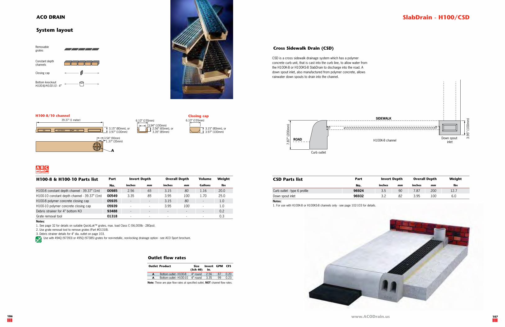
System layout
Outlet flow rates
D
Debris strainer to fit 4” bottom outlets.
3.0
0" (7
6m
m)
1.2
5" (3
2m
m)
Lip sits on invert
of channel

www.ACODrain.us
H200SK-13 Parts list Part Invert Depth Overall Depth Volume Weight
No. inches mm inches mm Gallons lbs
Constant depth channel (no grate) - 39.37” (1m) 63456 3.94 100 5.12 130 3.7 66.4 Load Class E longitudinal grate - 19.69” (0.5m) PowerLok™ 72263 - - - - - 26.4 Load Class F slotted grate - 19.69” (0.5m) PowerLok™ 02449 - - - - - 30.8 Load Class F 4-bolt grate - 19.69” (0.5m) 99591 - - - - - 26.4Replacement bolt 95526 - - - - - 0.1Tamper resistant bolt for 4-bolt grate 138127 - - - - - 0.1PowerLok™ safety clip 10443 - - - - - 0.1Steel closing cap 93460 - - 5.12 130 - 1.0 Debris strainer for 4” bottom knockout 93488 - - - - - 0.2 Grate removal tool 01318 - - - - - 0.3
Bottom knockoutH100SK-10 - 4”
H200SK-13 - 4” & 6”
H300SK-13 - 6” & 8”
Constant depthchannels
Closing cap
Removablegrates
7.87” (200mm)
6.30” (160mm)
2.80” (71mm)
5.12” (130mm) 5.12” (130mm)
39.37" (1 meter) 10.24” (260mm) 10.24” (260mm)
3.94” (100mm)
B
A
5.12” (130mm) 5.12” (130mm)
39.37" (1 meter)
6.30” (160mm)
1.73” (44mm)
B
14.17” (360mm)
11.81” (300mm)
14.17” (360mm)
3.94” (100mm)
A
3.94” (100mm) 3.94” (100mm)
39.37" (1 meter) 6.10” (155mm)
2.95” (75mm)
3.54” (90mm)1.37” (35mm)
A
3.94” (100mm)
6.10” (155mm)
ACO DRAIN SlabDrain - H100SK/H200SK/H300SK
H300SK-13 Parts list Part Invert Depth Overall Depth Volume Weight
No. inches mm inches mm Gallons lbs
Constant depth channel (no grate) - 39.37” (1m) 63466 3.94 100 5.12 130 5.5 82.2Load Class E longitudinal grate - 19.69” (0.5m) PowerLok™ 96833 - - - - - 64.0Load Class F slotted grate - 19.69” (0.5m) PowerLok™ 02445 - - - - - 50.0Load Class F 4-bolt grate - 19.69” (0.5m) 99592 - - - - - 50.2Replacement bolt 95526 - - - - - 0.1Tamper resistant bolt for 4-bolt grate 138127 - - - - - 0.1PowerLok™ safety clip 10443 - - - - - 0.1Steel closing cap 93470 - - 5.12 130 - 1.4Grate removal tool 01318 - - - - - 0.3
Notes:
1. See page 74 for details on grates.
2. Debris strainer details for 4” dia. outlet on page 103.
Notes:
1. See page 84 for details on grates.
2. Debris strainer details for 4” dia. outlet on page 103.
H300SK-13 channel
Notes:
1. See page 94 for details on grates.
Closing cap
H100SK-10 channel Closing cap
H200SK-13 channel Closing cap
Outlet Product Size (Sch 40)
Invertin.
GPM CFS
A Bottom outlet - H100SK 4” round 2.95 93 0.21A Bottom outlet - H200SK 4” round 4.00 108 0.24A Bottom outlet - H300SK 6” round 4.00 243 0.54B Bottom outlet - H200SK 6” round 4.00 243 0.54B Bottom outlet - H300SK 8” round 4.00 432 0.96
Note: These are pipe flow rates at specified outlet, NOT channel flow rates.
H100SK-10 Parts list Part Invert Depth Overall Depth Volume Weight
No. inches mm inches mm Gallons lbs
Constant depth channel (no grate) - 39.37” (1m) 93412 2.56 65 3.15 80 1.2 43.5 Load Class F longitudinal grate - 19.69” (0.5m) PowerLok™ 96096 - - - - - 13.6Load Class F slotted grate - 19.69” (0.5m) PowerLok™ 96082 - - - - - 12.3 Load Class F 4-bolt grate - 19.69” (0.5m) 99590 - - - - - 10.8
Replacement bolt 95526 - - - - - 0.1Tamper resistant bolt for 4-bolt grate 138127 - - - - - 0.1
PowerLok™ safety clip 10443 - - - - - 0.1Steel closing cap 93410 - - 3.15 80 - 1.0 Debris strainer for 4” bottom knockout 93488 - - - - - 0.2 Grate removal tool 01318 - - - - - 0.3
104 105
Outlet flow rates
D
System layout
www.ACODrain.us
ROAD
SIDEWALK
Curb outlet
Down spout inletH100K-8 channel
3.9
5”
(100m
m)
7.8
7”
(200m
m)
Bottom knockoutH100-8/H100-10 - 4”
Constant depthchannels
Closing cap
Removablegrates
ACO DRAIN SlabDrain - H100/CSD
Notes:
1. See page 32 for details on suitable QuickLok™ grates, max. load Class C (56,000lb - 280psi).
2. Use grate removal tool to remove grates (Part #01318).
3. Debris strainer details for 4” dia. outlet on page 103.
Use with 494Q (97393) or 495Q (97385) grates for non-metallic, non-locking drainage option - see ACO Sport brochure.
H100-8 & H100-10 Parts list Part Invert Depth Overall Depth Volume Weight
No. inches mm inches mm Gallons lbs
H100-8 constant depth channel - 39.37” (1m) 00985 2.56 65 3.15 80 1.16 20.0
H100-10 constant depth channel - 39.37” (1m) 00549 3.35 85 3.95 100 1.70 25.0
H100-8 polymer concrete closing cap 05935 - - 3.15 80 - 1.0
H100-10 polymer concrete closing cap 05939 - - 3.95 100 - 1.0
Debris strainer for 4” bottom KO 93488 - - - - - 0.2
Grate removal tool 01318 - - - - - 0.3
CSD Parts list Part Invert Depth Overall Depth Weight
No. inches mm inches mm lbs
Curb outlet - type 6 profile 96924 3.5 90 7.87 200 12.7
Down spout inlet 96932 3.2 82 3.95 100 6.0
Cross Sidewalk Drain (CSD)
Notes:
1. For use with H100K-8 or H100KS-8 channels only - see page 102-103 for details.
3.94” (100mm)3.15” (80mm), or3.97” (100mm)
39.37" (1 meter) 6.10” (155mm) 6.10” (155mm)
2.56” (65mm), or3.35” (85mm)
3.54” (90mm)1.37” (35mm)
3.15” (80mm), or3.97” (100mm)
A
H100-8/10 channel Closing cap
CSD is a cross sidewalk drainage system which has a polymer
concrete curb unit, that is cast into the curb line, to allow water from
the H100K-8 or H100KS-8 SlabDrain to discharge into the road. A
down spout inlet, also manufactured from polymer concrete, allows
rainwater down spouts to drain into the channel.
106 107
Outlet Product Size (Sch 40)
Invertin.
GPM CFS
A Bottom outlet - H100-8 4” round 2.56 87 0.20A Bottom outlet - H100-10 4” round 3.35 99 0.23
Note: These are pipe flow rates at specified outlet, NOT channel flow rates.
Outlet flow rates
D
System layout

www.ACODrain.us
Selection criteria
Light to medium duty loads
Constant depth channels
Multiple grate options to meet legal requirements
Multiple grate options to meet design requirements
D
5.12"6.85"
4.00"
3.62"
Typical applications
� Rail stations
� Parking garages
� Office buildings
� Airports
� Roof top gardens
Specifically for use in suspended slab where any liquid permeating through the pavement is
collected and directed into the trench drain.
Loading is determined by grate, up to Load Class C (25 ton).
For membrane applications above a habitable area, ACO Building Drainage offers ProfiLine
and other suitable products manufactured from stainless steel that are installed entirely
above the membrane.
MembraneDrain
108 109
Constant depth
MembraneDrain - External elevated slab drain
4inch
Limited hydraulic capacity
Product can be used towards LEED & EPA requirements
Resistant to many everyday
chemicals. Check page 139
Key dimensions

www.ACODrain.us
Weep holes
Used with H100-8/H100-10 channel -
MembraneDrain subframe fits directly on
the H100-8/H100-10 channels.
See page 106 for details.
Grates - Sit directly into the
MembraneDrain subframe and lock into
position with DrainLok™ or QuickLok™.19.69" (500mm)
4.92" (125mm)1.18" (30mm)
0.15" (4mm)
1.18" (30mm)
Half meter subframe End view
Membrane collects liquids that seep through surface materials.
Membrane - Is clamped between channel
and subframe. Maximum membrane of 1/2”
(12.7mm) can be accommodated - ensure
weep holes are not blocked if using a
thick or hot-mopped membrane. Liquids
seep through the pavement, collect on the
membrane (not supplied by ACO) and drain
into channel.
Weep holes - Along each side
allow liquids collecting on the
membrane to run into the channel.
Each weep hole opening is 1.18”
(30mm) x 0.15” (4mm).
Clamping device - An inverted ‘U’ shaped
locking bar is fitted to the H100-8/H100-
10 channel. The locking bar is fitted to the
MembraneDrain subframe. Two bolts allow
connection between the two bars and hold
the membrane tight.
End caps and accessories -
Are available from the H100-8/
H100-10 range.
See page 106 for details.
MembraneDrain Parts list
Notes:
1. For H100-8/H100-10 channel information see page 106.
Clamping device
Membrane end cap - Cut down and use
top part of K100 closing cap to close end
of subframe (Part #96822). See page 28
for details.
DrainLok™ grate MembraneDrain
subframe
Membrane
H100-8/H100-10Locking spring for
QuickLok™ grates
Clamping device
Section through MembraneDrain system
5.12" (130mm)
6.85" (174mm)
4.00" (100mm)
3.62" (92mm)
To calculate overall depth, add 3.62”, membrane thickness and channel depth
Ground line
ACO DRAIN
MembraneDrain features
Description Part No. Invert Depth Overall Depth Weight
Galv. Stainless inches mm inches mm lbs
MembraneDrain subframe - 19.69” (0.5m) 96903 96918 - - 3.62 92 9.7
MembraneDrain clamping device 96905 96913 - - - - 0.9
MembraneDrain
110 111
Slab details - For
reinforcement seek
engineering advice.
Locking bar with QuickLok™ locking mechanism
Inverted U locking bar fits in channel and locks subframe unit and channel together
Two assembly screws
Assembly scews

www.ACODrain.us
FlowDrain FG200 - 8” wide fiberglass system
Selection criteria
FG200 is an 8” wide fiberglass system with choice of steel slotted Class C (25 ton) or
ductile iron Class E (60 ton) grates. Grates are bolted into the steel frame with 2 bolts per
18” section.
FlowDrain - FG200
112 113
Typical applications
� Parking lots & garages
� Airports
� Gas stations
� Industrial areas
� Commercial areas
� Internal applications
11”
7” to 20”
8”
108’ continuous slope
8inch
Light to heavy industrial duty loads
Multiple grate options to meet legal requirements
Increased hydraulic capacity
Constant depth and/or sloped depth channels
Multiple grate options to meet design requirements
Product can be used towards LEED & EPA requirements
Resistant to many everyday
chemicals. Check page 139
D200,000lbProof Load
Key dimensions

www.ACODrain.us
ACO DRAIN
FlowDrain features
Bolted grates -
FG200 grates are
lockable with two
½” - 13 x 1½” bolts
fixing directly into steel
frame at 18” (457mm)
intervals.
Installation brackets - Provide
simple and easy installation using
No. 4 or 5 rebar.
Sloped (1.0%) channel units - 9’ (2.75 meter) long
units provide 108' (32.9 meter) continuous slope.
Equates to 1/8” fall per linear foot. Four constant
depth channels extend run lengths. Four 3’ (0.915
meter) units and accessories also available.
Direction arrows - Sticker on side of
channel indicates flow direction and
ensures channels are installed correctly.
Fiberglass - A lightweight material that is
made from polyester resin binder reinforced
by glass matting and fibers.
See page 136 for material properties.
Interconnecting end profiles - Allow easy
and effective joining of channels. Sealant
can be used to create sealed joints. Nelson studs - Attached to
frame, act as concrete anchors
to secure channels into concrete
surround.
Choice of grates - In various materials
and styles (including ADA compliant) for
applications up to Load Class E.
Snap-fit studs - Hold channel body securely to
frame and allows quick assembly on-site. Supplied
with frame.
Choice of steel frame - Provides grate support
and protects channel edge from damage. Available
in black coated, galvanized and stainless steel.
Bracing blocks - Supplied to brace
deeper channels during concrete pour,
details on how to position are shown on
a sticker on each channel.
FlowDrain - FG200
FG200 8” internal width
114 115

ACO DRAIN
Channels
Constant depth
channels
Sloping
channels
3 ft channels
Catch basins
F660
F880
Removable
grates
Closingendcapsfemale/male
F801
F802
F803
F804
F805
F806
F807
F808
F809
F8010
F8011
F8012
Outlet endcap4”/6”/8”
Bottom outletadapter 4”/6”/8”
Accessories
F803N
F806N
F809N
F8012N
F803N3
F806N3
F809N3
F8012N3
116
ACO DRAIN
System layout
119
Outlet cap
Fits outside deep/male end of all channels.
Manufactured from polypropylene with
choice of black coated, stainless or
galvanized steel end rail. Guides aid cutting
to correct height. Seal using
appropriate flexible sealant.
Bell end connection to fit 4”,
6” or 8” Schedule 40 pipes.
Note: For depth 801-804
channels ACO recommends
removal of unused sections
of the bell end to ensure
adequate pavement material
coverage.
Male closing cap
Fits outside deep/male end
of all channels. Manufactured
from polypropylene with choice
of black coated, stainless
or galvanized steel end rail.
Guides aid cutting to correct
height. Seal using appropriate
flexible sealant.
www.ACODrain.us
Female closing cap
Fits inside shallow/
female end of channel.
Manufactured from
polypropylene with
choice of black coated,
stainless or galvanized
steel end frame.
Guides aid cutting
to correct height. Seal using appropriate
flexible sealant.
3 ft channels
Constant depth channels in 4
depths to supplement the 9’
channels for easier layouts.
Choice of 3’ black coated,
stainless or galvanized steel
frame connects to channel body
using simple snap-fit studs.
F660 & F880 catch basins
One piece fiberglass catch basins with choice of
black coated, stainless or galvanized steel frame,
lockable steel bar or ductile iron slotted grate and
plastic trash bucket.
Accessories include 4”, 6” and 8” Schedule 40
pipe adapters and channel collars to connect
channel to catch basin.
See page 121 for details.
Vertical outlet adapter
4”, 6” or 8”
Schedule
40 vertical
outlet adapter
manufactured from
polypropylene.
Can be secured to underside of channel
using appropriate flexible sealant to provide
vertical bell end for easy attachment to 4”,
6” or 8” Schedule 40 pipe. Can be used
anywhere along channel.
9 ft channels
1.0% sloped channels in 9’ lengths and
12 depths which connect to create 108’
(32.9 meters) continuously sloping trench
run. Constant depth channels are available
in 4 depths and can be used to create
non-sloped runs or inserted in sloped runs
to increase length. Choice of 9’ black
coated, stainless or galvanized steel frame
connects to channel body using simple
snap-fit studs.
FlowDrain - FG200

36” (915mm)
9.00” (229mm)
10.63” (270mm)
6.88” (175mm)to
20.38” (517mm)
8.00” (203mm)
Closing cap (Female)
9 ft channel
3 ft channel
Vertical outlet adapter
Closing cap (Male) Outlet end cap
A
11.00” (280mm)8.00” (203mm)
1.61” (41mm)
B
C
Bell end to fit 4”, 6” or 8” Sch. 40 pipe
108” (2744mm)
9.00” (229mm)
10.63” (270mm)
20.2
5”
(51
4m
m)
2.00” (50mm)
20.3
8”
(51
7m
m)
10.63” (270mm) 2.00” (50mm)
D
10.63” (270mm)
20.3
8”
(517m
m)
2.00” (50mm)
EF
Bell end to fit 4”, 6” or 8”Sch. 40 pipe
Channel collar
Pipe adapter
FlowDrain - FG200
118
FF880 Catch Basin
FF660 Catch Basin
117
Catch basins F660 F880
Outlet Size (Sch 40)
Invertin.
GPM CFS Invertin.
GPM CFS
G 4” round 26.50 269 0.60 27.50 275 0.61
H 6” round 26.50 594 1.32 27.50 606 1.35
I 8” round 26.50 1032 2.30 27.50 1055 2.35
Note: These are pipe flow rates at specified outlet, NOT channel flow rates.Catch Basin flow rates without trash bucket - using trash bucket reduces flow.
Channels
Outlet Size (Sch 40)
Invertin.
GPM CFS
A 4” round 7.88 154 0.34
A 4” round 20.25 246 0.54
B 6” round 7.88 346 0.77
B 6” round 20.25 553 1.23
C 8” round 7.88 616 1.37
C 8” round 20.25 982 2.18
D 4” round 9.00 145 0.33
D 4” round 20.25 233 0.54
E 6” round 10.13 330 0.76
E 6” round 20.25 510 1.17
F 8” round 12.38 635 1.46
F 8” round 20.25 880 2.03
Outlet flow rates
8.66” (220mm)
9.40” (239mm)
7.31” (186mm)
7.31” (106mm)24.47” (622mm) 22.97” (583mm)
26
.6”
(67
6m
m)
G 4” Pipe adapter
H 6” Pipe adapter
I 8” Pipe adapter
17.95” (456mm) 175.39” (391mm)
27.6
9”
(703m
m)
24.43” (620mm) 35.00” (889mm)
18.43” (468mm) 27.36” (694mm)
19.7
4”
(501m
m)
98171
11.40” (289mm)
10.66” (271mm)
www.ACODrain.us
Product dimensions
ACO DRAIN

www.ACODrain.us
Parts table - FG200 Catch basins Part Volume Weight
No. Gallons lbs
F660 catch basin - 24” x 12” 98069 27.00 22.0 F660 black coated steel frame 97995 - 13.8 F660 galvanized steel frame 98008 - 14.4 F660 stainless steel frame* 98013 - 14.4 F660 plastic trash bucket 98067 - 5.0 F880 catch basin - 24” x 24” 98075 55.00 22.0 F880 black coated steel frame 98021 - 23.2 F880 galvanized steel frame 98034 - 24.2 F880 stainless steel frame* 98048 - 24.2 F880 plastic trash bucket 98059 - 8.4 FG200 channel/catch basin adapter 98171 - 1.14” pipe plain end adapter 97425 - 0.4 6” pipe plain end adapter 97438 - 0.6 8” pipe plain end adapter 97444 - 0.9
Fiberglass catch basins
Fiberglass catch basins are available with a variety of frames and grates. Channel collars
are available to connect all depths of channel on any side of the catch basin.
Pipe adapters are available to allow inlet/outlet pipe connections at any position on the
catch basin.
F660 catch basin
Grates - a choice of galvanized or stainless steel
bar or slotted ductile iron grates, locked in place
with 2 bolts. See page 123.
Trash bucket - plastic trash bucket designed to
collect debris that has collected in the trench and
washed into the catch basin.
Frame - coated black, galvanized or stainless
steel frame attached to catch basin body with
snap-fit studs.
Catch basin body - fiberglass body in choice of
2 sizes.
Channel collar - adapter to enable smooth
transition of any depth FG200 channel on any
side. Can be cut to correct height.
Pipe adapter - plain end adapter to allow inlet or
outlet pipes to be easily attached to the outer wall
of catch basin at any position. Available for 4”, 6”
and 8” Schedule 40 pipes.
F880 catch basin
FlowDrain - FG200
121
* Grade 304 stainless steel frames.ACO recommends use of non-galvanized grates with stainless steel frames to avoid galvanic corrosion.
ACO DRAIN
FG200 Parts table Part No. Invert Depth Overall Depth Vol Wgt
Inches mm Inches mm Gal lbs
female male female male female male female male
F801 Sloped channel - 108” (2.75m) 99006 6.75 7.88 172 200 6.88 8.01 175 203 18.37 11.0F802 Sloped channel - 108” (2.75m) 99013 7.88 9.00 200 229 8.01 9.13 203 232 22.58 12.0F803 Sloped channel - 108” (2.75m) 99021 9.00 10.13 229 257 9.13 10.26 232 260 26.79 13.0F803N Constant depth channel - 108” (2.75m) 99048 10.13 10.13 257 257 10.26 10.26 260 260 28.80 15.5F803N3 Constant depth channel - 36” (0.915m) 99034 10.13 10.13 257 257 10.26 10.26 260 260 9.60 5.2F804 Sloped channel - 108” (2.75m) 99055 10.13 11.25 257 286 10.26 11.38 260 289 31.00 14.1F805 Sloped channel - 108” (2.75m) 99062 11.25 12.38 286 314 11.38 12.51 289 318 35.21 15.2F806 Sloped channel - 108” (2.75m) 99071 12.38 13.50 314 343 12.51 13.63 318 346 39.42 16.3F806N Constant depth channel - 108” (2.75m) 99095 13.50 13.50 343 343 13.63 13.63 346 346 41.50 16.3F806N3 Constant depth channel - 36” (0.915m) 99084 13.50 13.50 343 343 13.63 13.63 346 346 13.83 5.5F807 Sloped channel - 108” (2.75m) 99109 13.50 14.63 343 371 12.63 14.76 346 375 43.63 17.4F808 Sloped channel - 108” (2.75m) 99116 14.63 15.75 371 400 14.76 15.88 375 403 47.84 18.5F809 Sloped channel - 108” (2.75m) 99123 15.75 16.87 400 429 15.88 17.00 403 432 52.05 19.6F809N Constant depth channel - 108” (2.75m) 99145 16.87 16.87 429 429 17.00 17.00 432 432 54.10 19.6F809N3 Constant depth channel - 36” (0.915m) 99132 16.87 16.87 429 429 17.00 17.00 432 432 18.00 6.5F810 Sloped channel - 108” (2.75m) 99156 16.87 18.00 429 457 17.00 18.13 432 460 56.26 20.7F811 Sloped channel - 108” (2.75m) 99162 18.00 19.13 457 486 18.13 19.26 460 489 60.47 21.8F812 Sloped channel - 108” (2.75m) 99175 19.13 20.25 486 514 19.26 20.38 489 518 64.68 23.0F812N Constant depth channel - 108” (2.75m) 99192 20.25 20.25 514 514 20.38 20.38 518 518 66.76 23.0F812N3 Constant depth channel - 36” (0.915m) 99186 20.25 20.25 514 514 20.38 20.38 518 518 22.25 7.7Black coated steel frame - 108” (2.75m) 97066 - - - - - - - - - 57.9 Black coated steel frame - 36” (0.915m) 98524 - - - - - - - - - 19.3 Galvanized steel frame - 108” (2.75m) 97079 - - - - - - - - - 57.9 Galvanized steel frame - 36” (0.915m) 98538 - - - - - - - - - 19.3 Stainless steel frame - 108” (2.75m)* 97087 - - - - - - - - - 57.9 Stainless steel frame - 36” (0.915m)* 98545 - - - - - - - - - 19.3 Closing cap (female) with black end frame 98365 - - - - 20.38 20.38 518 518 - 1.1 Closing cap (female) with galv. steel end frame 98386 - - - - 20.38 20.38 518 518 - 1.1 Closing cap (female) with S/S end frame 98375 - - - - 20.38 20.38 518 518 - 1.1 Closing cap (male) with black end frame 98363 - - - - 20.38 20.38 518 518 - 1.3 Closing cap (male) with galv. steel end frame 98382 - - - - 20.38 20.38 518 518 - 1.3 Closing cap (male) with S/S end frame 98372 - - - - 20.38 20.38 518 518 - 1.3 Outlet cap (male) with black end frame 98361 20.25 20.25 514 514 20.38 20.38 518 518 - 1.8 Outlet cap (male) with galv. steel end frame 98381 20.25 20.25 514 514 20.38 20.38 518 518 - 1.8 Outlet cap (male) with S/S end frame 98373 20.25 20.25 514 514 20.38 20.38 518 518 - 1.8 Vertical outlet adapter - 4”, 6” or 8” outlet 98103 20.25 20.25 514 514 20.38 20.38 518 518 - 1.6
Notes:
1. Invert depths are for the channel body & frame assembled.
2. Channel weights are for fiberglass body only.
3. Closing/Outlet caps can be cut down to suit all channels.
4. Add 2” to length of each channel for female joining flange (only applicable at shallowest end of trench run).
5. Frames supplied with plastic snap-fit studs for connecting to fiberglass body.
6. See page 122 for grate details.
* Grade 304 stainless steel frames, ACO recommends the use of non-galvanized grates with stainless steel frames to avoid galvanic corrosion.
120

www.ACODrain.us
1 2 3
Grate removalUsing wrench or socket set to tighten. If using a
torque wrench do not set to more than 15 ft. lbs.
To remove grates use wrench or socket set.
Carefully store bolts for refitting of grates.
Position grate onto channel, align holes in grate
with matching holes in frame cross bar.
Fit grate
Bolted FG200 grates offer mechanical, secure fixing of grates into the channel frame. Two
bolts per 18” grate section lock into cross bars in the steel frame. Care must be taken to
ensure that all bolts are secure and are not overtightened which can damage the frame.
Bolted grates
Description PartNo.
Length
inches (m)
Slot Size
inches
Intake area
sq. in.
Wgt
lbs
C Load Class C - 56,000lbs - EN 1433 739psi Commercial vehicle
Bar steel
Galvanized 1
Stainless* 2
97452
97455
24” (0.6m)
24” (0.6m)1.0 x 3.3 456.0 63.8 Bolt 54.3
61.0
* Grade 304 stainless steel.
E Load Class E - 135,000lbs - EN1433 1,773psi IndustrialE 600
Slotted iron
Iron 3 97453 24” (0.6m) 1.2 x 5.5 226.0 206.0 Bolt 23.8
Ductile iron to ASTM A 536-84 - minimum grade 64-45-12
Notes:
1. Supplied with 2 galvanized steel socket head bolts (½” - 13 x 1½”) - replacement part 93895.
2. Supplied with 2 stainless steel socket head bolts (½” - 13 x 1½”) - replacement part 93897.
3. Supplied with 2 stainless steel hex head bolts (½” - 13 x 1½”) - replacement part 93892.
FlowDrain - FG200
Description PartNo.
Length
inches (m)
Slot Size
inches
Intake area
sq. in.
Wgt
lbs
C Load Class C - 56,000lbs - EN 1433 739psi Commercial vehicle
Bar steel
Galvanized 1
Stainless* 2
97443
97442
24” (0.6m)
24” (0.6m)1.0 x 3.3 267.0 35.2 Bolt 54.3
61.0
* Grade 304 stainless steel.
E Load Class E - 135,000lbs - EN1433 1,773psi Industrial
E 600
Slotted iron
Iron 3 97449 24” (0.6m) 1.2 x 6.1 avg 130.0 75.0 Bolt 31.0
Ductile iron to ASTM A 536-84 - minimum grade 64-45-12
Description PartNo.
Length
inches (m)
Slot Size
inches
Intake area
sq. in.
Wgt
lbs
C Load Class C - 56,000lbs - EN 1433 968psi Commercial vehicle
Bar steel
Galvanized 1
Stainless* 2
93899
93891
36” (0.9m)
36” (0.9m)1.0 x 3.6 264.0 28.6 Bolt 54.3
61.0
* Grade 304 stainless steel.
E Load Class E - 135,000lbs - EN1433 2,321psi Industrial
Slotted iron
Iron 3 93896 18” (0.45m) 0.61 x 7.87 58.7 25.2 Bolt 29.0
Ductile iron to ASTM A 536-84 - minimum grade 64-45-12. This grate complies with RR-F-621E ‘200,000lb proof load’ test.
Longitudinal iron
Iron 3 93893 18” (0.45m) 1.75 x 0.25 35.0 28.2 Bolt 31.9
Ductile iron to ASTM A 536-84 - minimum grade 64-45-12. This grate complies with RR-F-621E ‘200,000lb proof load’ test.
Available FG200 grates
Available F880 grates
Available F660 grates
122 123
200,000lbProof Load
Notes:
1. Supplied with 4 galvanized steel socket head bolts (½” - 13 x 1½”) - replacement part 93895.
2. Supplied with 4 stainless steel socket head bolts (½” - 13 x 1½”) - replacement part 93897.
3. Supplied with 2 stainless steel hex head bolts (½” - 13 x 1½”) - replacement part 93892.
200,000lbProof Load
200,000lbProof Load
200,000lb proof load compliant(Page 128)
Key ASME A112.6.3 - 2001 Heel resistant less than 0.31” (8mm) (Page 140)
Compliant with Americans with Disabilities Act of 1990 Section 4.5.4 (Page 140)
Bicycle Safe compliant to Australian Standard AS 3996 - 2006 (Page 140)
Anti-slip grates - BPN over 24 (Page 140)
Locking mechanism
ACO DRAIN
Heel safe equal or less than 0.25” (6.5mm) (Page 140)


![Icsdsleepdisorders Pgs[1]](https://img.pdfslide.us/doc/110x75/554938a8b4c905144d8b4a95/icsdsleepdisorders-pgs1.jpg)