Embed Size (px)
Citation preview

Tutorial: Coal Combustion with Eddy Break Up (EBU)
Model
Introduction
The purpose of this tutorial is to provide guidelines and recommendations for setting upand solving a coal combustion case using coal calculator.
This tutorial demonstrates how to do the following:
• Set up and solve a coal combustion case.
• Solve the case using appropriate solver settings.
• Postprocess the resulting data.
Prerequisites
This tutorial is written with the assumption that you have completed Tutorial 1 from theANSYS FLUENT 14.5 Tutorial Guide, and that you are familiar with the ANSYS FLUENTnavigation pane and menu structure. Some steps in the setup and solution procedure willnot be shown explicitly.
If you have not used EBU model before, it would be helpful to first refer to the ANSYSFLUENT 14.5 User’s Guide and the ANSYS FLUENT 14.5 Tutorial Guide.
Problem Description
A 3D cutaway of the furnace is shown in Figure 1. Two annular inlets on the left-hand sideand a circular outlet on the right-hand side are visible. Only one quarter of this geometryis modeled due to symmetry. The inner annular inlet has inner and outer radii of 0.055 mand 0.067 m respectively. The outer annular inlet has inner and outer radii of 0.07 m and0.117 m respectively. The outlet radius is 0.425 m.
Coal and carrier air enter the combustion chamber through the inner annular region. Hot,swirling, secondary air enters through the outer annular region. Combustion takes placeand the products exit at the pressure outlet.
c© ANSYS, Inc. December 5, 2012 1
Coal Combustion with Eddy Break Up (EBU) Model
Preparation
1. Copy the files, coal-ebu.msh.gz and coal-ebu.c, to your working folder.
2. Use FLUENT Launcher to start the (3D) version of ANSYS FLUENT.
3. Enable Double Precision in the Options list.
4. Click the Environment tab and make sure that Setup Compilation Environment for UDFis enabled.
The path to the .bat file which is required to compile the UDF will be displayed assoon as you enable Setup Compilation Environment for UDF.
If the Environment tab does not appear in the FLUENT Launcher dialog box by default,click the Show More Options button to view the additional settings.
Figure 1: Problem Figure
Setup and Solution
Step 1: Mesh
1. Read the mesh file (coal-ebu.msh.gz).
2. Change the Periodic Type of periodic to Rotational.
Boundary Conditions −→ periodic −→ Edit...
(a) Select Rotational in the Periodic Type list.
(b) Click OK to close the Periodic dialog box.
2 c© ANSYS, Inc. December 5, 2012
Coal Combustion with Eddy Break Up (EBU) Model
Step 2: General Settings
General
1. Check the mesh.
General −→ Check
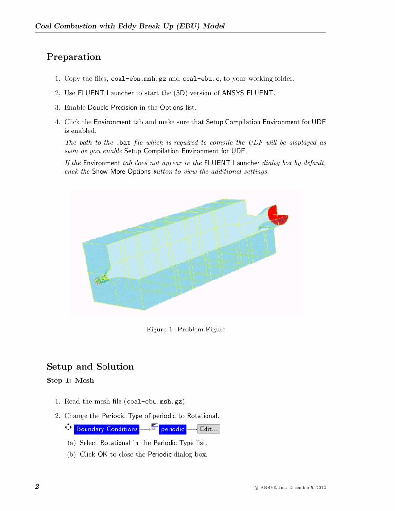
2. Display the mesh.
General −→ Display Mesh...
(a) Select all the surfaces from the Surfaces selection list.
(b) Click Display and close the Mesh Display dialog box.
Figure 2: Mesh Display
Step 3: Models
Models
1. Enable the Energy Equation.
Models −→ Energy −→ Edit...
2. Select the standard k-epsilon (2 eqn) turbulence model.
Models −→ Viscous −→ Edit...
c© ANSYS, Inc. December 5, 2012 3

Coal Combustion with Eddy Break Up (EBU) Model
3. Select the Discrete Ordinates model.
Models −→ Radiation −→ Edit...
(a) Select Discrete Ordinates (DO) in the Model list.
The Radiation Model dialog box expands to show the related inputs.
(b) Set Energy Iterations per Radiation Iteration to 1.
(c) Set Theta Divisions and Phi Divisions to 4 in the Angular Discretization group box.
(d) Set Theta Pixels and Phi Pixels to 3 in the Angular Discretization group box.
(e) Click OK to close the Radiation Model dialog box.
Click OK in the Information dialog box.
4. Select the Species Transport model.
Models −→ Species −→ Edit...
(a) Select Species Transport in the Model list.
(b) Enable Volumetric in the Reactions list.
(c) Select Eddy Dissipation from the Turbulence-Chemistry Interaction list.
(d) Click on Coal Calculator....
4 c© ANSYS, Inc. December 5, 2012

Coal Combustion with Eddy Break Up (EBU) Model
Note: Coal calculator is a tool to convert available inputs like proximate andultimate analysis, and heating value of a fuel, into simulation inputs likestoichiometric coefficients of volatile break up or combustion reaction, stan-dard state enthalpy of volatile species, volatile and combustible fractions ofcombusting material, and so on. This conversion is quick and accurate andtherefore, manual calculations and errors are avoided.
i. Specify Proximate Analysis as shown in the table.
Parameter ValueVolatile 0.51Fixed Carbon 0.34
Ash 0.08Moisture 0.07
Table 1: Proximate Analysis
c© ANSYS, Inc. December 5, 2012 5
Coal Combustion with Eddy Break Up (EBU) Model
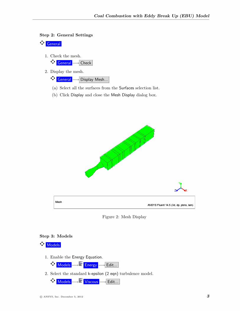
ii. Specify Ultimate Analysis (DAF) as shown in the table.
Parameter ValueC 0.80H 0.05
O 0.13N 0.02
Table 2: Ultimate Analysis (DAF)
iii. Select Two-Step Reaction from the group of Mechanism.
iv. Enable Wet Combustion from the Options group box.
v. Enter 3.058e+7 for Coal As-Received HCV.
vi. Enter 50 for Volatile Molecular Weight.
vii. Enter 0.775 for CO/CO2 Split in Reaction-1 Products.
viii. Enter 1.1 for High Temperature Volatile Yield.
ix. Enter 1200 for Coal Dry Density.
Note: CO/CO2 split is the fraction of CO in the volatile combustion reac-tion.
x. Click OK and close the Coal Calculator dialog box.
Note: A Warning dialog box is displayed to inform you that a number ofmixture materials, their properties and reactions have been set up. Fromthe Warning dialog box note down the values set for Volatile N massfraction and Char N mass fraction. You will be using these values later(Step 13). Click OK to close the Warning dialog box.
(e) Click OK to close the Information dialog box, which informs about the change inmaterial properties and methods.
(f) Click OK to close the Species Model dialog box.
Click OK in the Information dialog box.
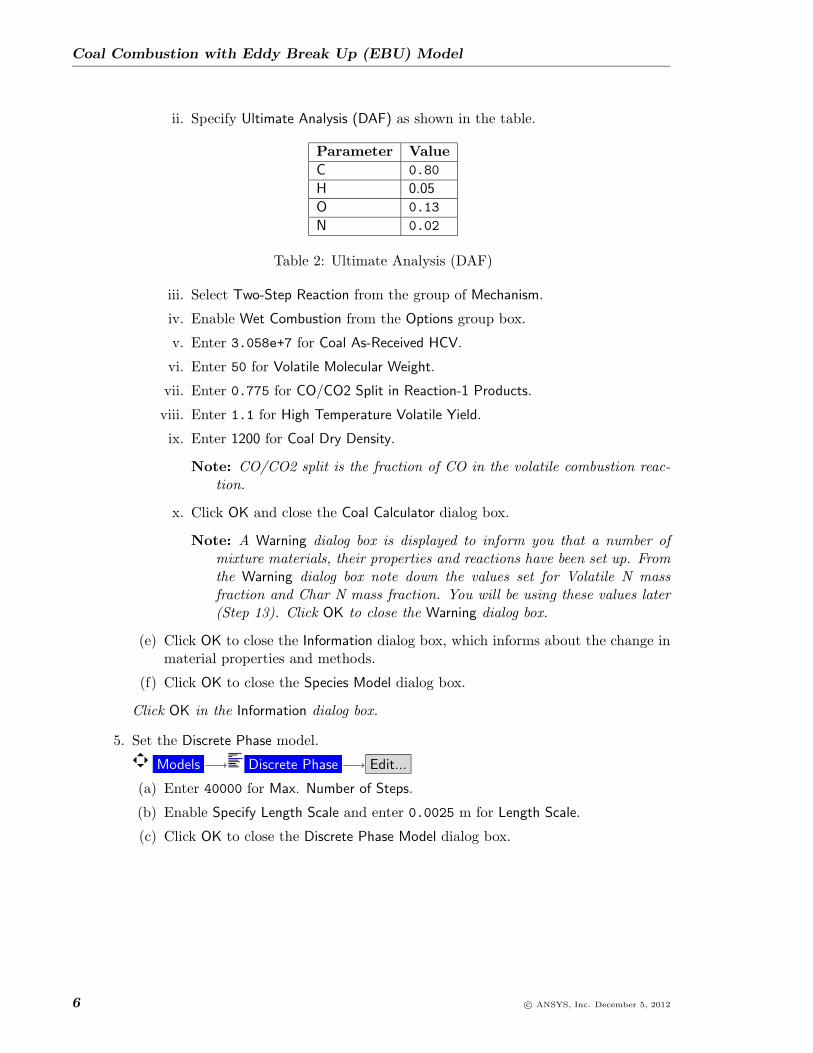
5. Set the Discrete Phase model.
Models −→ Discrete Phase −→ Edit...
(a) Enter 40000 for Max. Number of Steps.
(b) Enable Specify Length Scale and enter 0.0025 m for Length Scale.
(c) Click OK to close the Discrete Phase Model dialog box.
6 c© ANSYS, Inc. December 5, 2012

Coal Combustion with Eddy Break Up (EBU) Model
Step 4: Injections
1. Define 9 injections from surface v-1.
Define −→Injections...
(a) Click the Create button to open the Set Injection Properties dialog box.
(b) Select surface from the Injection Type drop-down list.
(c) Select v-1 from the list of Release From Surfaces.
(d) Select Combusting from the Particle Type group box.
(e) In the Point Properties tab, enter 23.11 for Z-Velocity and 343 for Temperature.
(f) Enter 0.00018264 for Total Flow Rate.
(g) Click the Turbulent Dispersion tab and enable Discrete Random Walk Model.
i. Enter 10 for Number of Tries.
(h) Click the Wet Combustion tab and enable Wet Combustion Model.
c© ANSYS, Inc. December 5, 2012 7
Coal Combustion with Eddy Break Up (EBU) Model
(i) Select h20 from the Evaporating Species drop-down list.
Liquid material and liquid fraction are automatically added.
(j) Click OK to set injection-0.
(k) The properties specific to each injection are shown in the table:
Injection Name Diameter (m) Flow Rateinjection-0 1e-6 0.00018264injection-1 5e-6 0.00073056injection-2 1e-5 0.00127848injection-3 2.5e-5 0.00438336injection-4 5e-5 0.00584448injection-5 7.5e-5 0.00347016injection-6 0.0001 0.00146112injection-7 0.0002 0.00073056injection-8 0.0003 0.00018264
Table 3: Specific Injection Properties
(l) Retain the default values for the other parameters.
(m) Close the Injections dialog box.
Step 5: Materials
1. Modify the properties for the coal-volatiles-air mixture.
Materials −→ Mixture −→ Create/Edit...
(a) Set the physical properties for following parameters:
Parameter ValueThermal Conductivity polynomial
The first and second temperature coefficientsare 0.01006 and 5.413e-5 respectively.
Viscosity polynomialThe first and second temperature coefficientsare 9.18e-6 and 3.161e-8 respectively.
Absorption Coefficient wsggm-domain-based
Scattering Coefficient constant with a value of 0.5
Table 4: Properties for Parameters
(b) Click Change/Create.
8 c© ANSYS, Inc. December 5, 2012

Coal Combustion with Eddy Break Up (EBU) Model
2. Set the properties for the combusting particle coal-particle.
Materials −→ coal-particle −→ Create/Edit...
Property ValueCp 1100Vaporization Temperature 400Binary Diffusivity 3e-5Swelling Coefficient 2React. Heat Fraction Absorbed 0by Solid
Devolatilization Model 50kinetics/diffusion-limitedMass Diffusion-Limited Rate Constant = 5e-12
Combustion Model Kinetics-Limited Rate Pre-Exponential Factor = 6.7Kinetics-Limited Rate Activation Energy = 1.138e8
Table 5: Combusting Particle Material Properties
Vaporization temperature of coal is 773 K. To start the reactions, lower the tempera-ture to 343 K and once the flame shape is obtained, it will be changed to the originalvalue.
3. Set the properties for the droplet particle.
Materials −→ water-liquid −→ Create/Edit...
(a) Select piecewise-linear from the Cp(Specific Heat) drop-down list and retain thedefault values.
(b) Enter 360 for Vaporization Temperature.
(c) Select convection/diffusion controlled from the Vaporization Model drop-down list.
(d) Click Change/Create.
4. Close the Create/Edit Materials dialog box.
Step 6: Compiling the Interpreted User Defined Functions (UDFs)
These functions will be used later to set the boundary conditions. For more information oninterpreted UDFs, refer to the ANSYS FLUENT 14.5 UDF Manual.
Define −→ User-Defined −→ Functions −→Interpreted...
1. Enter the name of the C function (coal-ebu.c) for Source File Name.
2. Specify the C preprocessor to be used in the CPP Command Name.
Keep the default Stack Size setting of 10000, unless the number of local variables inyour function will cause the stack to overflow. In this case, set the Stack Size to anumber that is greater than the number of local variables used.
c© ANSYS, Inc. December 5, 2012 9

Coal Combustion with Eddy Break Up (EBU) Model
3. Select the Use Contributed CPP option if you want to use the preprocessor suppliedby ANSYS, Inc., instead of using your own.
4. Click Interpret and close the Interpreted UDFs dialog box.
In case there are errors while interpreting, keep the dialog box open and continuedebugging and interpreting simultaneously until no more errors are reported.
Step 7: Boundary Conditions
Boundary Conditions
1. Set the boundary conditions for v-1 as specified in Table 6.
Boundary Conditions −→ v-1 −→ Edit...
Parameter ValueVelocity Magnitude 23.11 m/sSpecification Method Intensity and Hydraulic Diameter
Turbulence Intensity 10%Hydraulic Diameter 0.013 mTemperature 343 KInternal Emissivity 1Species Mass Fractions o2 = 0.2315Discrete Phase BC Type escape
Table 6: Boundary Conditions for v-1
2. Set the boundary conditions for v-2 as specified in Table 7.
Boundary Conditions −→ v-2 −→ Edit...
Parameter ValueVelocity Specification Method Components
Coordinate System Cylindrical (Radial, Tangential, Axial)
Radial-Velocity 0Tangential-Velocity udf vinlet2wvel
Axial-Velocity udf vinlet2uvel
Specification Method Intensity and Hydraulic Diameter
Turbulence Intensity 12 %Hydraulic Diameter 0.047 mTemperature 573 KSpecies Mass Fractions o2 = 0.2315
Table 7: Boundary Conditions for v-2
3. Set the boundary conditions for p-1 as specified in Table 8.
Boundary Conditions −→ p-1 −→ Edit...
10 c© ANSYS, Inc. December 5, 2012

Coal Combustion with Eddy Break Up (EBU) Model
Parameter ValueGauge Pressure 0Specification Method Intensity and Hydraulic Diameter
Backflow Turbulence Intensity 10%Backflow Hydraulic Diameter 1 mBackflow Total Temperature 1000 KSpecies Mass Fractions o2 = 0.2315
Table 8: Boundary Conditions for p-1
4. Set the boundary conditions for the wall zones. The Temperature and Internal Emis-sivity are specified in Table 9.
Zone Temperature Internal Emissivityw-1 343 0.6w-2 573 0.6w-3 873 0.6w-4 1273 0.5w-5 udf wall5temp 0.5w-6 udf wall6temp 0.5w-7 udf wall7temp 0.5w-8 1323 0.5w-9 1073 0.5
Table 9: Wall Boundary Conditions
Step 8: Non-Reacting Flow Solution
1. Disable Volumetric reactions.
Models −→ Species −→ Edit...
2. Set Number of Continuous Phase Iterations per DPM Iteration to 0 to avoid injection ofparticles in this step.
Models −→ Discrete Phase −→ Edit...
3. Set convergence to none.
Monitors (Residuals)−→ Edit...
(a) Select none from Convergence Criterion drop-down list.
4. Set the solution controls.
Solution Methods
(a) Select Coupled from the Scheme drop-down list.
c© ANSYS, Inc. December 5, 2012 11

Coal Combustion with Eddy Break Up (EBU) Model
(b) Select PRESTO! from the Pressure drop-down list.
(c) Enable Set All Species Discretization Together.
5. Set the under-relaxation factors.
Solution Controls
(a) Enter 50 for Flow Courant Number.
(b) Enable Set All Species URFs Together.
(c) Click on Equations... and de-select Discrete Ordinates from the list of Equations.
6. Initialize the solution.
Solution Initialization
(a) Select Standard Initialization from the Initialization Methods group box.
(b) Enter 100 for Turbulent Dissipation Rate.
(c) Enter 0.2315 for o2.
(d) Enter 1355 for Temperature.
(e) Click Initialize.
7. Start the calculation by requesting 100 iterations.
Run Calculation
8. Save the case and data files coal-ebu-cold.cas/dat.gz.
Step 9: Initiate Reacting Flow Solution
1. Change the settings in the Discrete Phase Model dialog box.
Models −→ Discrete Phase −→ Edit...
(a) Set the Number of Continuous Phase Iterations per DPM Iteration to 1.
(b) In the Physical Models tab enable Pressure Dependent Boiling.
Click OK in the Information dialog box.
(c) Click the Numerics tab.
i. Enable the term Enable Node Based Averaging in the Averaging group box.
ii. Ensure that Average DPM Source Terms is enabled.
iii. Enter 6 for Gaussian Factor in the Kernel Settings group box.
iv. Click OK to close the Discrete Phase Model dialog box.
2. Enable Volumetric reactions.
Models −→ Species −→ Edit...
3. Patch high temperature and product species mass fractions in reaction zone.
Adapt −→Region...
12 c© ANSYS, Inc. December 5, 2012

Coal Combustion with Eddy Break Up (EBU) Model
(a) Select Cylinder from the Shapes list.
(b) Enter the Input Coordinates as shown in the dialog box.
(c) Click Mark and close the Region Adaption dialog box.
4. Patch the following values in the reaction zone.
Solution Initialization −→ Patch...
(a) Select cylinder-r0 in the Registers to Patch selection list and patch the followingvalues:
Temperature 2000h2o 0.01co2 0.01
(b) Close the Patch dialog box.
5. Set the Under-Relaxation Factors as follows:
Solution Controls
Species 0.95Energy 0.95
Discrete Phase Sources 1
6. Request 1 iteration.
Run Calculation
7. Save the case and data files (coal-ebu-react-start.cas.gz andcoal-ebu-react-start.dat.gz).
File −→ Write −→Case & Data...
c© ANSYS, Inc. December 5, 2012 13

Coal Combustion with Eddy Break Up (EBU) Model
8. Change the Number of Continuous Phase Iterations per DPM Iteration to 25.
Models −→ Discrete Phase −→ Edit...
9. Change the Vaporization Temperature (k) to 773.
Materials −→ coal-particle −→ Create/Edit
10. Set the Under-Relaxation Factor for Discrete Phase Sources to 0.5.
Solution Controls
11. Request 500 more iterations.
Run Calculation
12. Save the case and data files (coal-ebu-react.cas.gz andcoal-ebu-react.dat.gz).
File −→ Write −→Case & Data...
Step 10: Reacting Flow Solution Including Radiation
1. Change the solution control parameters.
Solution Controls
(a) Click on Equations and select Discrete Ordinates from the list of Equations.
(b) Click OK to close the equations dialog box.
2. Request 100 additional iterations.
Run Calculation
3. Save the case and data files (coal-ebu-react-rad.cas.gz and coal-ebu-react-rad.dat.gz).
File −→ Write −→Case & Data...
4. Change the under-relaxation factors.
Solution Controls
(a) Enter 1 for Species and Energy.
5. Request 500 additional iterations.
Run Calculation
6. Save the case and data files (coal-ebu-react-rad-1.cas.gz and coal-ebu-react-rad-1.dat.gz).
File −→ Write −→Case & Data...
14 c© ANSYS, Inc. December 5, 2012
Coal Combustion with Eddy Break Up (EBU) Model
Step 11: Reacting Flow Solution Including Particle-Radiation Interaction
1. Enable Particle Radiation Interaction from the Physical Models tab in Discrete PhaseModel dialog box.
Models −→ Discrete Phase −→ Edit...
Click OK in the Information dialog box.
2. Ensure that Particle Emissivity and Particle Scattering Factor are set to 0.9.
Materials −→ Combusting Particle −→ Create/Edit...
Note: It is better to use different values of emmisivity for Char, Volatile, and ash. Thiscan be done using a UDF for particle emissivity. DEFINE DPM PROPERTY canbe used for this purpose and a sample function is provided in the emissivity.c file.There are some macros in this UDF which will work only with compiled UDF,This tutorial is created with interpreted UDF. Therefore, varying emissivity isnot used here.
3. Change the under-relaxation factors.
Solution Controls
(a) Enter 0.25 for Discrete Phase Source.
4. Request another 2000 iterations.
Run Calculation −→ Calculate
5. Save the case and data files (coal-ebu-react-rad-final.cas.gz andcoal-ebu-react-rad-final.dat.gz).
Step 12: Postprocessing
1. Check the mass balance for convergence.
Reports −→ Fluxes −→ Set Up...
(a) Select Mass Flow Rate in the Options list.
(b) Select all the zones from the Boundaries selection list and click Compute.
This is net gas phase mass flux.
2. Check the net heat transfer.
Reports −→ Fluxes −→ Set Up...
(a) Select Total Heat Transfer Rate in the Options list.
(b) Select all the zones from the Boundaries selection list and click Compute.
This is net gas phase heat transfer.
3. Display filled contours of velocity magnitude (Figure 3) on x=0m-plane.
4. Display filled contours of static temperature (Figure 4).
c© ANSYS, Inc. December 5, 2012 15

Coal Combustion with Eddy Break Up (EBU) Model
Figure 3: Contours of Velocity Magnitude
Figure 4: Contours of Static Temperature
16 c© ANSYS, Inc. December 5, 2012
Coal Combustion with Eddy Break Up (EBU) Model
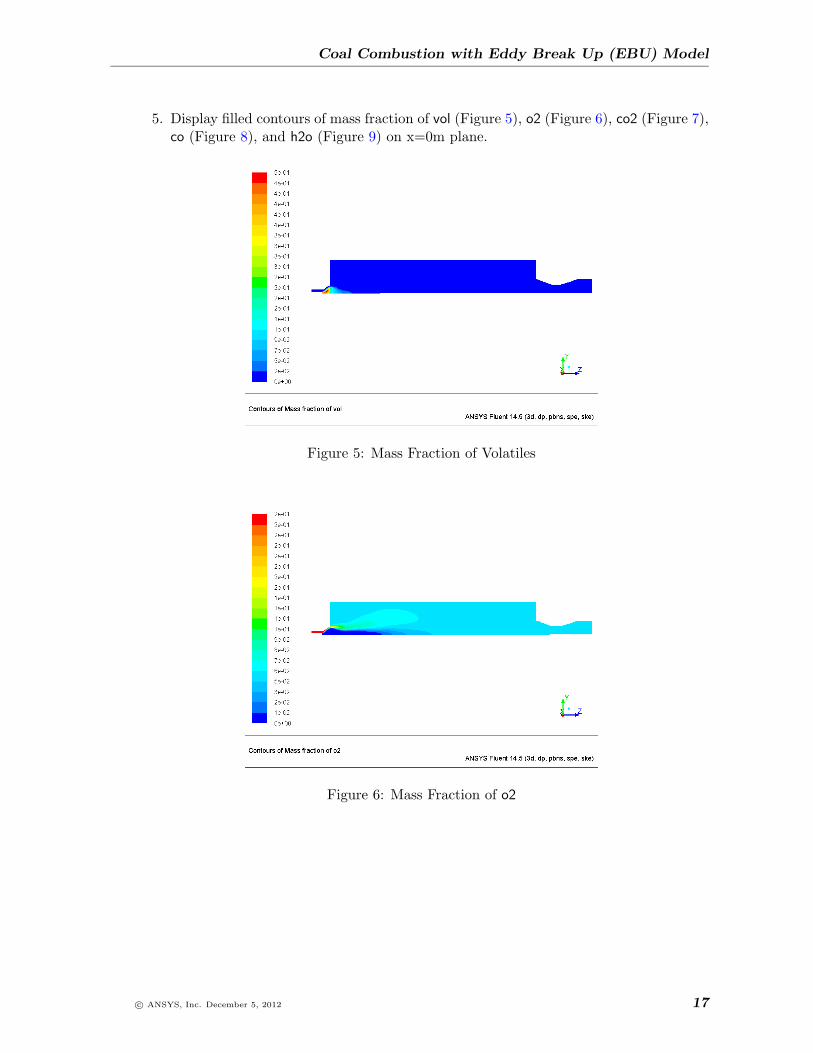
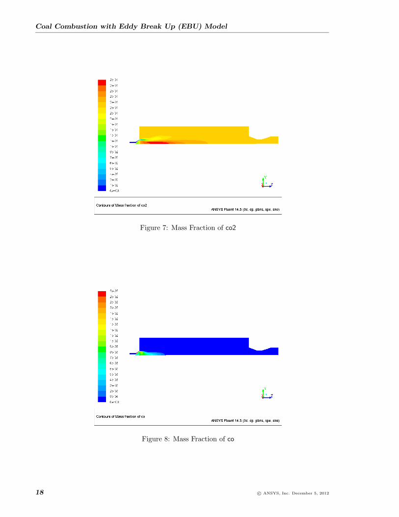
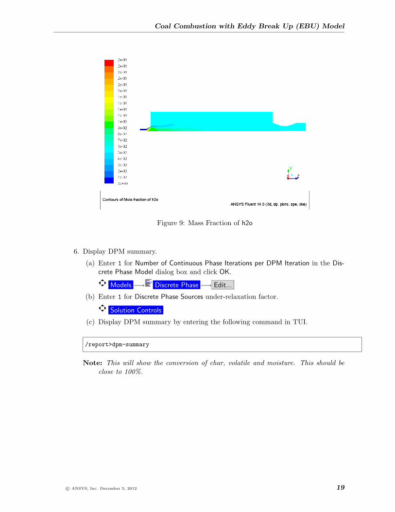
5. Display filled contours of mass fraction of vol (Figure 5), o2 (Figure 6), co2 (Figure 7),co (Figure 8), and h2o (Figure 9) on x=0m plane.
Figure 5: Mass Fraction of Volatiles
Figure 6: Mass Fraction of o2
c© ANSYS, Inc. December 5, 2012 17
Coal Combustion with Eddy Break Up (EBU) Model
Figure 7: Mass Fraction of co2
Figure 8: Mass Fraction of co
18 c© ANSYS, Inc. December 5, 2012
Coal Combustion with Eddy Break Up (EBU) Model
Figure 9: Mass Fraction of h2o
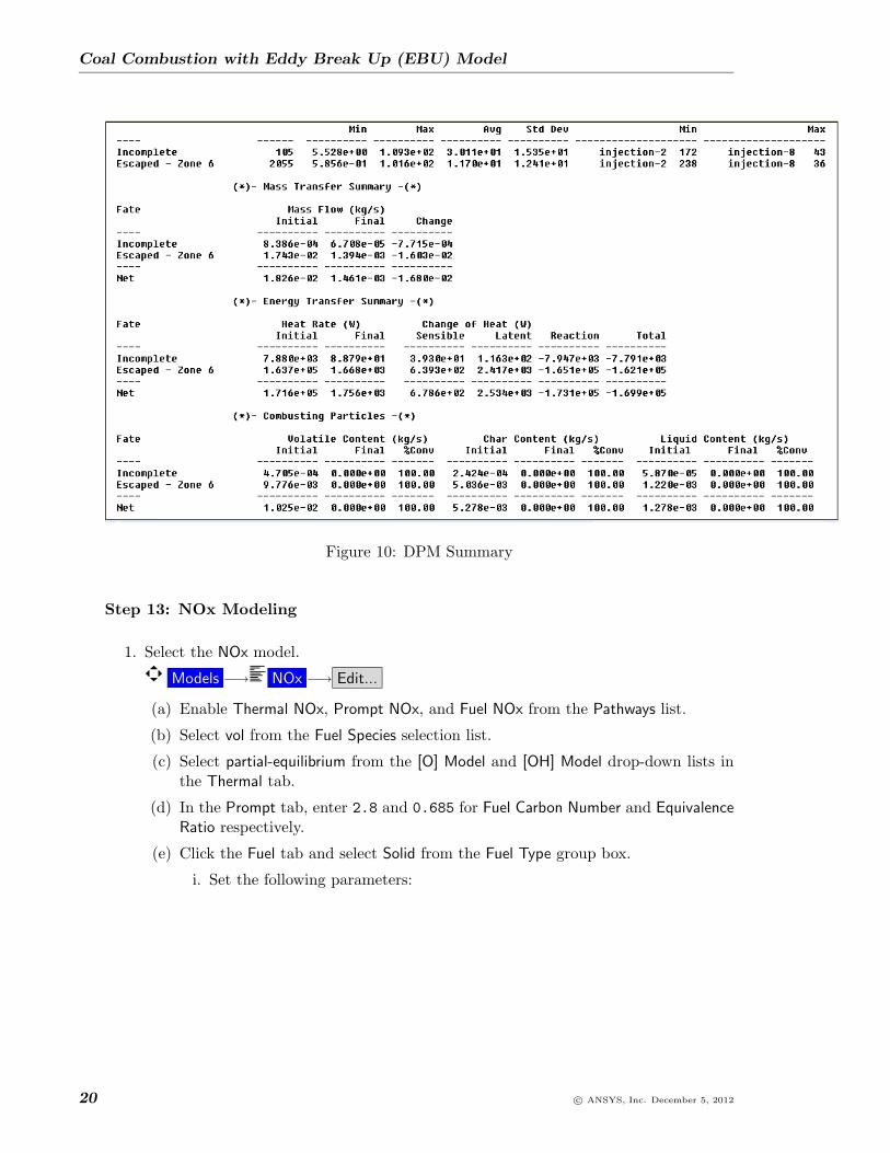
6. Display DPM summary.
(a) Enter 1 for Number of Continuous Phase Iterations per DPM Iteration in the Dis-crete Phase Model dialog box and click OK.
Models −→ Discrete Phase −→ Edit...
(b) Enter 1 for Discrete Phase Sources under-relaxation factor.
Solution Controls
(c) Display DPM summary by entering the following command in TUI.
/report>dpm-summary
Note: This will show the conversion of char, volatile and moisture. This should beclose to 100%.
c© ANSYS, Inc. December 5, 2012 19
Coal Combustion with Eddy Break Up (EBU) Model
Figure 10: DPM Summary
Step 13: NOx Modeling
1. Select the NOx model.
Models −→ NOx −→ Edit...
(a) Enable Thermal NOx, Prompt NOx, and Fuel NOx from the Pathways list.
(b) Select vol from the Fuel Species selection list.
(c) Select partial-equilibrium from the [O] Model and [OH] Model drop-down lists inthe Thermal tab.
(d) In the Prompt tab, enter 2.8 and 0.685 for Fuel Carbon Number and EquivalenceRatio respectively.
(e) Click the Fuel tab and select Solid from the Fuel Type group box.
i. Set the following parameters:
20 c© ANSYS, Inc. December 5, 2012

Coal Combustion with Eddy Break Up (EBU) Model
Fuel Type SolidN Intermediate hcn/nh3/no
Volatile N Mass Fraction 0.009091Partition Fractions
hcn 0.9nh3 0.1
Char N Conversion no
Char N Mass Fraction 0.041176
The values of volatile and char N mass fractions are obtained from Step 3.4,where you set the Species Transport Model.
Note: Refer to Section 23.1.1.7.2 Setting Solid(Coal) Fuel NOx Parameters inthe ANSYS FLUENTUser’s Guide for details on how to calculate volatileand char N mass fractions.
(f) Click the Turbulence Interaction tab and select temperature from the PDF Modedrop-down list.
(g) Enter 20 for PDF Points.
(h) Click Apply and close the NOx Model dialog box.
2. Set Number of Continuous Phase Iterations per DPM Iteration to 0 in the Discrete PhaseModel and click OK.
Models −→ Discrete Phase −→ Edit...
3. Change the solution control parameters.
Solution Controls
(a) Increase the Under-Relaxation Factors for Pollutant no, Pollutant hcn, and Pollutantnh3 to 1.
(b) Deselect all equations except Pollutant no, Pollutant hcn, and Pollutant nh3 fromthe Equations selection list.
Solution Controls −→ Equations...
4. Request for 100 iterations.
Run Calculation
5. Save the case and data flies (coal-ebu-final-no.cas.gz and coal-ebu-final-no.dat.gz).
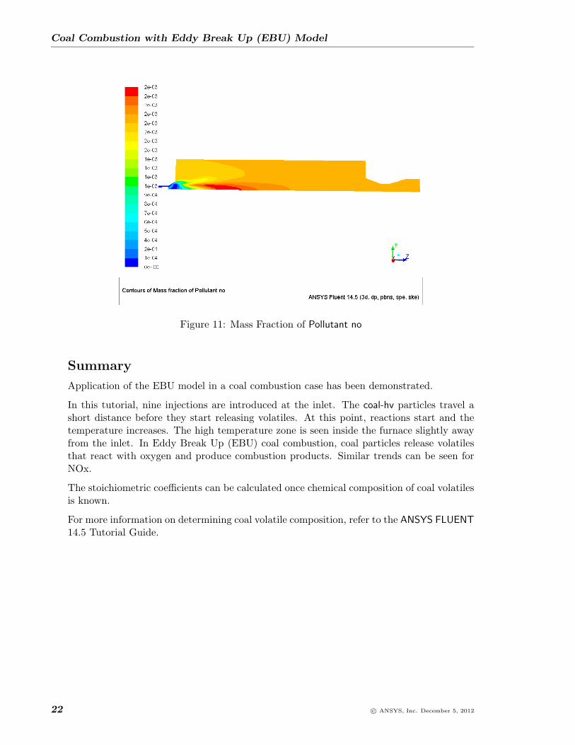
6. Display contours of mass fraction of Pollutant no on x=0m plane (Figure 11).
Graphics and Animations −→ Contours −→ Set Up...
(a) Select NOx... and Mass Fraction of Pollutant no from the Contours of drop-downlists.
(b) Select x=0m plane from the Surfaces selection list.
(c) Click Display and close the Contours dialog box.
c© ANSYS, Inc. December 5, 2012 21
Coal Combustion with Eddy Break Up (EBU) Model
Figure 11: Mass Fraction of Pollutant no
Summary
Application of the EBU model in a coal combustion case has been demonstrated.
In this tutorial, nine injections are introduced at the inlet. The coal-hv particles travel ashort distance before they start releasing volatiles. At this point, reactions start and thetemperature increases. The high temperature zone is seen inside the furnace slightly awayfrom the inlet. In Eddy Break Up (EBU) coal combustion, coal particles release volatilesthat react with oxygen and produce combustion products. Similar trends can be seen forNOx.
The stoichiometric coefficients can be calculated once chemical composition of coal volatilesis known.
For more information on determining coal volatile composition, refer to the ANSYS FLUENT14.5 Tutorial Guide.
22 c© ANSYS, Inc. December 5, 2012