Embed Size (px)
Citation preview
Shah 1
DEVELOPMENT OF AN FE MODEL FOR FLEXPLI WITH UPPER BODY MASS FOR ENHANCED PEDESTRIAN SAFETY ASSESSMENT
Chirag, Shah Humanetics Innovative Solutions, Inc. USA
George, Hu Humanetics China China
Mark, Burleigh Humanetics Innovative Solutions, Inc. USA
Paper Number 19-0228
ABSTRACT
The FlexPLI GTR tool has been implemented with an Upper Body Mass (UBM) representing portion of the torso mass, hip joint rotation and the response time lag between leg and the upper body during pedestrian to vehicle accidents.
The new FlexPLI GTR UBM tool improves the test method at the end of the bumper test area of vehicle by eliminating unrealistic rotation of the FlexPLI GTR without UBM, bringing it closer to human lower extremity kinematics and loading. The tool is an enhancement to the current dummy technology by improving the pedestrian safety. The key benefit is that the UBM can be added to the existing standard FlexPLI GTR hardware being used in the current test procedures.
The FlexPLI GTR UBM finite element (FE) model is developed and validated against a selected test condition. The geometry and connectivity for the FlexPLI GTR UBM FE model are obtained from the hardware design. Material testing was carried out to obtain the material properties and implementation to the FE model for the rubber element representing the hip joint stiffness during rotation of upper body mass.
The initial findings of the FlexPLI GTR UBM FE model reveal that the model showed promising predictability for the simulated load-case.
INTRODUCTION
In US, on an average a pedestrian was killed nearly every 1.5 hours in traffic crashes and accounted for 16% of all traffic fatalities in 2016 [1]. In the same year, 5320 pedestrian died in road accidents in the EU which is 21% of all road fatalities [2]. The lower limb was found to be the most frequently injured body region with AIS 2 to 6 level injuries in 32.6% of pedestrian accidents worldwide.
In 1998, the European Enhanced Vehicle-Safety Committee proposed a test procedure to assess protection to the lower extremity of a pedestrian during a collision [3]. A legform Impactor composed of rigid long bones was utilized in this procedure. As opposed to a legform impactor with rigid bone parts, the Flexible Pedestrian Legform Impactor (FlexPLI) is more biofidelic especially for its long bone parts, which have human-like bending characteristics [4]. The FlexPLI also provides extended injury assessment capabilities, including long bone bending moment at multiple locations and knee ligament elongations in comparison to other pedestrian legforms [4].
In 2005, the FlexPLI Technical Evaluation Group (Flex-TEG) was settled under the ECE/WP29/GRSP/Informal Group on Pedestrian Safety in order to evaluate FlexPLI hardware performance. Another objective of the FLEX-TEG was to assess the impactor as a regulatory purpose test tool for a Global Technical Regulation on Pedestrian Safety (PS-GTR). The Japan Automobile Manufacturer Association, Inc. (JAMA) and Japan Automobile Research
Shah 2
Institute (JARI) continued to improve and upgrade FlexPLI, and in 2007 the 5th version, called Type GT (FlexPLI-GT) was produced. After the settlement of the Flex-TEG, the FlexPLI GT was evaluated and improved its performance, and the final 6th version, type GTR (FlexPLI GTR), was agreed by the FLEX-TEG members in April 2008 representing leg of the 50th percentile male right leg [5].
The FlexPLI GTR used in the current pedestrian regulatory and consumer programs is focused on assessing injuries to tibia bone and knee ligaments during a pedestrian car collision. The tool has been revised under the European Union (EU) project SENIORS (Safety-ENhancing Innovations for Older Road userS) to implement an Upper Body Mass (UBM) to the standard FlexPLI GTR hardware.
The current efforts describe the development of the FlexPLI GTR UBM finite element (FE) model and validation of the model against a selected test condition.
METHODS
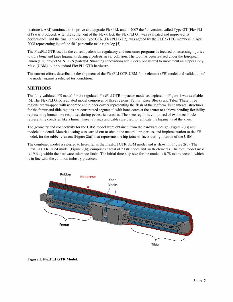
The fully validated FE model for the regulated FlexPLI GTR impactor model as depicted in Figure 1 was available [6]. The FlexPLI GTR regulated model comprises of three regions: Femur, Knee Blocks and Tibia. These three regions are wrapped with neoprene and rubber covers representing the flesh of the legform. Fundamental structures for the femur and tibia regions are constructed segmental with bone cores at the center to achieve bending flexibility representing human like responses during pedestrian crashes. The knee region is comprised of two knee blocks representing condyles like a human knee. Springs and cables are used to replicate the ligaments of the knee.
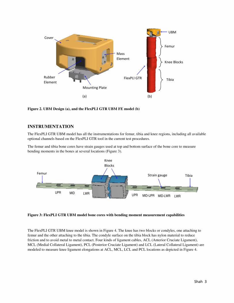
The geometry and connectivity for the UBM model were obtained from the hardware design (Figure 2(a)) and modeled in detail. Material testing was carried out to obtain the material properties, and implementation to the FE model, for the rubber element (Figure 2(a)) that represents the hip joint stiffness during rotation of the UBM.
The combined model is referred to hereafter as the FlexPLI GTR UBM model and is shown in Figure 2(b). The FlexPLI GTR UBM model (Figure 2(b)) comprises a total of 233K nodes and 340K elements. The total model mass is 19.6 kg within the hardware tolerance limits. The initial time-step size for the model is 0.78 micro-second, which is in line with the common industry practices.
Figure 1. FlexPLI GTR Model.
Femur
Knee Blocks
Tibia
Neoprene Rubber
Shah 3
(a)
(b)
Figure 2. UBM Design (a), and the FlexPLI GTR UBM FE model (b)
INSTRUMENTATION
The FlexPLI GTR UBM model has all the instrumentations for femur, tibia and knee regions, including all available optional channels based on the FlexPLI GTR tool in the current test procedures.
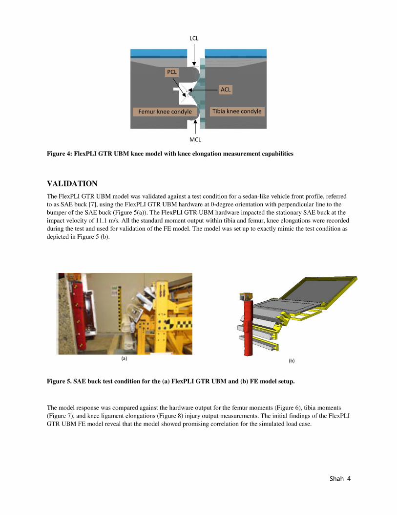
The femur and tibia bone cores have strain gauges used at top and bottom surface of the bone core to measure bending moments in the bones at several locations (Figure 3).
Figure 3: FlexPLI GTR UBM model bone cores with bending moment measurement capabilities
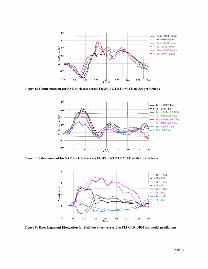
The FlexPLI GTR UBM knee model is shown in Figure 4. The knee has two blocks or condyles, one attaching to femur and the other attaching to the tibia. The condyle surface on the tibia block has nylon material to reduce friction and to avoid metal to metal contact. Four kinds of ligament cables, ACL (Anterior Cruciate Ligament), MCL (Medial Collateral Ligament), PCL (Posterior Cruciate Ligament) and LCL (Lateral Collateral Ligament) are modeled to measure knee ligament elongations at ACL, MCL, LCL and PCL locations as depicted in Figure 4.
Mass Element
Knee Blocks
UBM
Mounting Plate
Rubber Element
Femur Strain gauge Tibia
UPR MID LWR UPR MID-UPR MID-LWR LWR
Knee Blocks
Femur
Tibia
Cover
FlexPLI GTR
Shah 4
Figure 4: FlexPLI GTR UBM knee model with knee elongation measurement capabilities
VALIDATION
The FlexPLI GTR UBM model was validated against a test condition for a sedan-like vehicle front profile, referred to as SAE buck [7], using the FlexPLI GTR UBM hardware at 0-degree orientation with perpendicular line to the bumper of the SAE buck (Figure 5(a)). The FlexPLI GTR UBM hardware impacted the stationary SAE buck at the impact velocity of 11.1 m/s. All the standard moment output within tibia and femur, knee elongations were recorded during the test and used for validation of the FE model. The model was set up to exactly mimic the test condition as depicted in Figure 5 (b).
(a)
(b)
Figure 5. SAE buck test condition for the (a) FlexPLI GTR UBM and (b) FE model setup.
The model response was compared against the hardware output for the femur moments (Figure 6), tibia moments (Figure 7), and knee ligament elongations (Figure 8) injury output measurements. The initial findings of the FlexPLI GTR UBM FE model reveal that the model showed promising correlation for the simulated load case.
Femur knee condyle
LCL
Tibia knee condyle
PCL
ACL
MCL
Shah 5
Figure 6: Femur moment for SAE buck test versus FlexPLI GTR UBM FE model predictions
Figure 7: Tibia moment for SAE buck test versus FlexPLI GTR UBM FE model predictions
Figure 8: Knee Ligament Elongation for SAE buck test versus FlexPLI GTR UBM FE model predictions
Test – UPR FemurFE – UPR Femur Test – MID Femur FE – MID Femur Test – LWR Femur FE – LWR Femur
Test – UPR TibiaFE – UPR Tibia Test – MID-UPR Tibia FE – MID UPR Tibia Test – MID-LWR Tibia FE – MID-LWR Tibia Test – LWR Tibia FE - LWR Tibia
Test – ACL FE – ACL Test – PCL FE – PCL Test – MCL FE – MCL Test – LCL FE – LCL
Shah 6
CONCLUSIONS
The FlexPLI GTR UBM tool enables the assessment of the injury risk for the femur, closer to human-like lower extremity injury, and also the assessment of vehicles with a higher front profile. The FlexPLI GTR UBM FE model is currently being validated against a selected load case and will be further validated against additional load cases as they become available.
REFERENCES
[1] NHTSA 2016. “Traffic Safety Facts”, DOT HS 812 493.
[2] European Commission 2018. “Traffic Safety Basic Facts on Pedestrians”, European Commission, Directorate General for Transport, June 2018.
[3] European Enhanced Vehicle-safety Committee 1998. “Improved test methods to evaluate pedestrian protection afforded by passenger cars”, EEVC Working Group 17.
[4] Konosu A. and Tanahashi M. 2005. “Development of a biofidelic Flexible Pedestrian Leg-form Impactor (FLEX-PLI 2004) and Evaluation of its biofidelity at the Component and at the Assembly Level”, SAE paper No. 2005-01-1879.
[5] UN/ECE/WP29/GRSP/INF-GR-PS/Flex-TEG 2008. “First Technology Safety Systems Design Freeze Status FLEX-PLI GTR Development Mechanical Design”, TEG-054-Rev. 1, http://www.unece.org/trans/main/wp29/wp29wgs/wp29grps/pedestrian_FlexPLI.html
[6] Technical Document 2016. “FlexPLI GTR Regulated V1.0.2 Model Technical Report”, Humanetics Innovative Solutions, Inc.
[7] Pipkorn B., Forsberg C., Takahashi Y., Ikeda M., Fredriksson R., Svensson C., and Thesleff A. 2014. “Development and Component Validation of a Generic Vehicle Front Buck for Pedestrian Impact Evluation”, IRCOBI.