Embed Size (px)
Citation preview
ATD Technical Advisory Meeting on Dummy DesignThursday, May 15, 20147:00 am – 9:00 am EST
Humanetics Headquarters in Plymouth, MI and via WebEx
May 15, 2014Michael S. Beebe, Mark Brown, Joe Bastian, Paul Depinet, John Below
Humanetics Innovative Solutions, Inc.
5/15/2014
Agenda
• Petition Update
o Auto Alliance petition / NHTSA Small Female Jacket
Eurosid Abdomen
• ATD Component Updateso Hybrid III Upper Arm
o Small Female Skull Cap
o Hybrid III Lumbar
o Hybrid III Ankle J2949
o TNO 10
o FMVSS 226 Head form
o IRTRACC Update
•
• Harmonization Updateo Euro NCAP components
o H Standard Update
• Regulation Dummy Updateo WorldSID
o THOR
o Q3s
• Future Dummy Updateo Obese
o Abdominal Upgrade
©2013 Humanetics Innovative Solutions Inc. – Confidential & Proprietary 5-
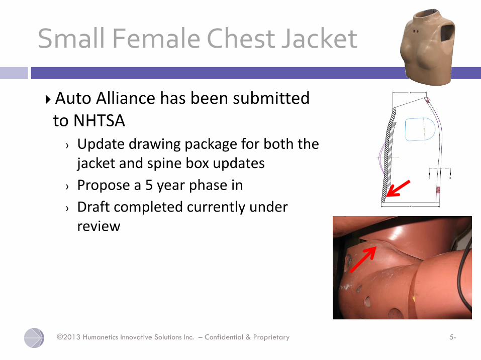
Small Female Chest Jacket
Auto Alliance has been submitted to NHTSA
› Update drawing package for both the jacket and spine box updates
› Propose a 5 year phase in
› Draft completed currently under review
5/15/2014
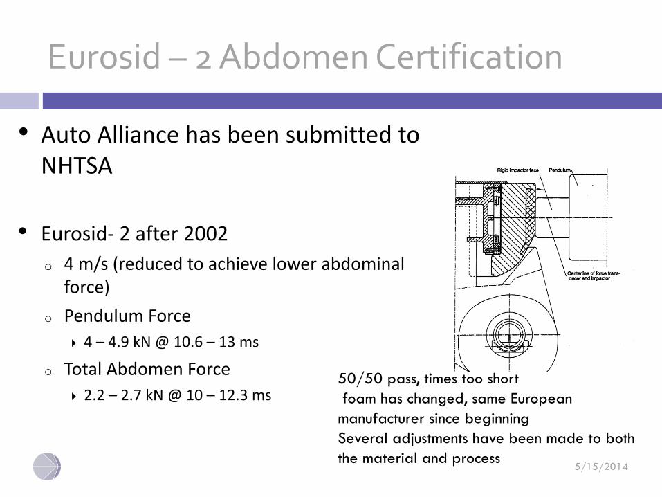
Eurosid – 2 Abdomen Certification
• Auto Alliance has been submitted to NHTSA
• Eurosid- 2 after 2002
o 4 m/s (reduced to achieve lower abdominal force)
o Pendulum Force
4 – 4.9 kN @ 10.6 – 13 ms
o Total Abdomen Force
2.2 – 2.7 kN @ 10 – 12.3 ms50/50 pass, times too short
foam has changed, same European
manufacturer since beginning
Several adjustments have been made to both
the material and process
©2013 Humanetics Innovative Solutions Inc. – Confidential & Proprietary 5-
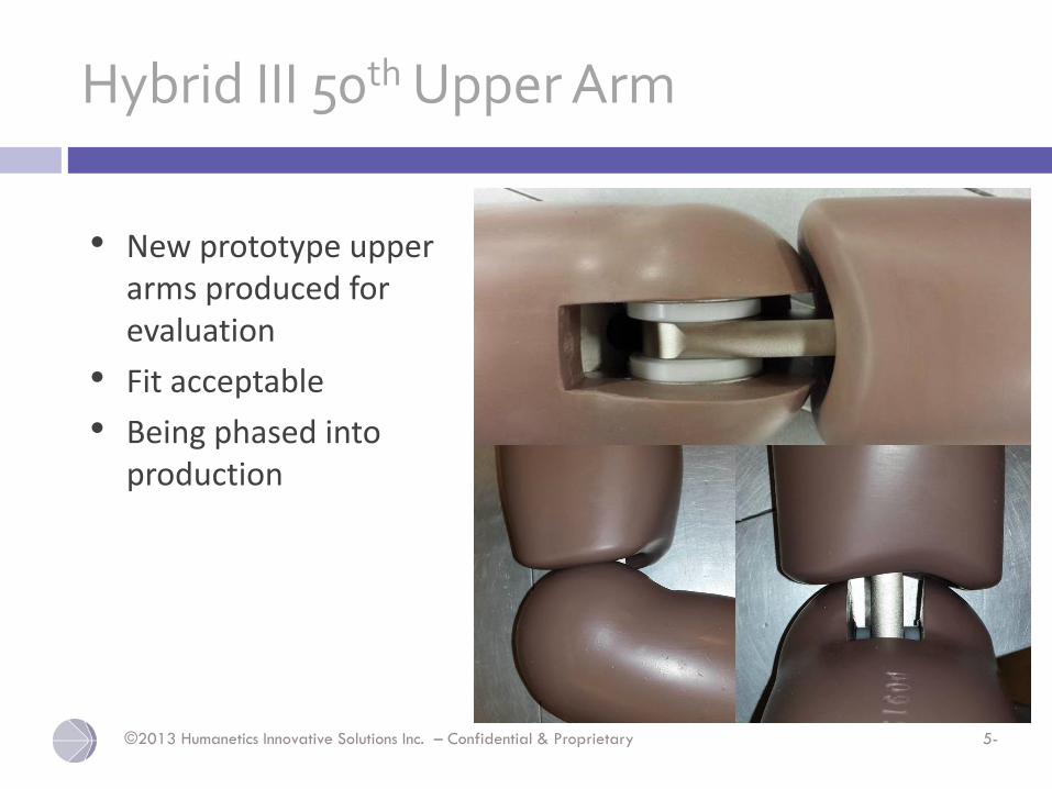
Hybrid III 50th Upper Arm
• New prototype upper arms produced for evaluation
• Fit acceptable
• Being phased into production
©2013 Humanetics Innovative Solutions Inc. – Confidential & Proprietary 5-
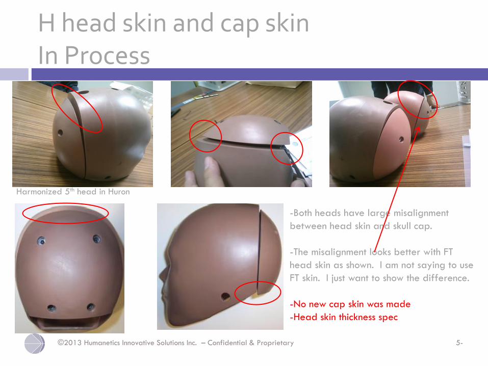
H head skin and cap skinIn Process
Harmonized 5th head in Huron
-Both heads have large misalignment
between head skin and skull cap.
-The misalignment looks better with FT
head skin as shown. I am not saying to use
FT skin. I just want to show the difference.
-No new cap skin was made
-Head skin thickness spec
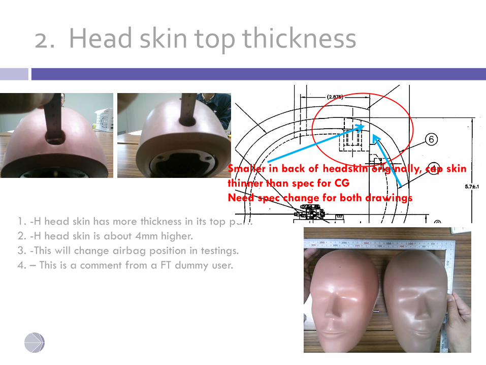
2. Head skin top thickness
1. -H head skin has more thickness in its top part.
2. -H head skin is about 4mm higher.
3. -This will change airbag position in testings.
4. – This is a comment from a FT dummy user.
Smaller in back of headskin originally, cap skin
thinner than spec for CG
Need spec change for both drawings
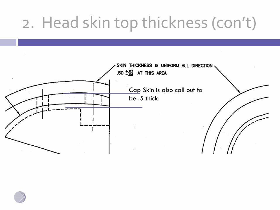
2. Head skin top thickness (con’t)
Cap Skin is also call out to
be .5 thick
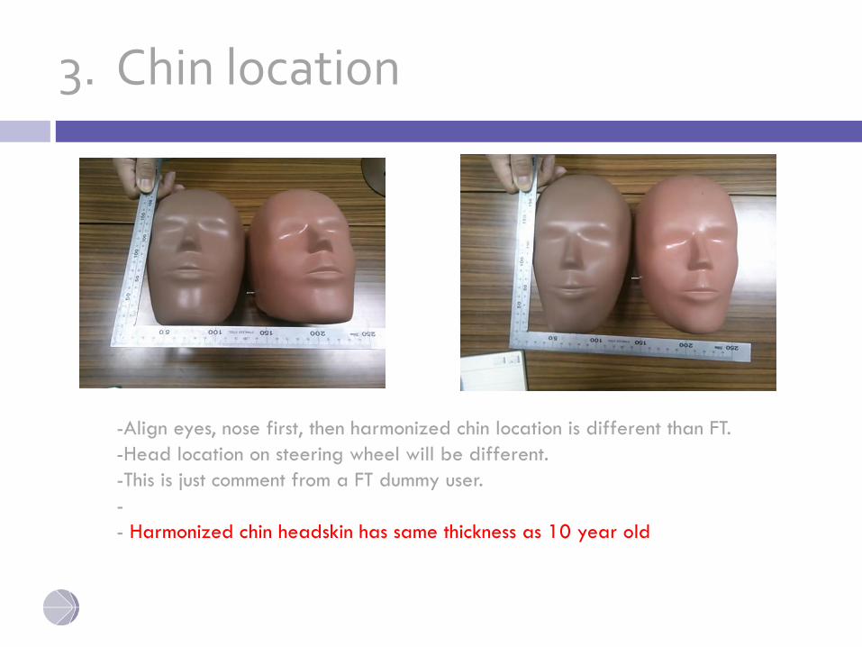
3. Chin location
-Align eyes, nose first, then harmonized chin location is different than FT.
-Head location on steering wheel will be different.
-This is just comment from a FT dummy user.
-
- Harmonized chin headskin has same thickness as 10 year old
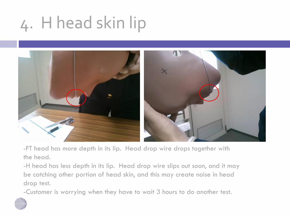
4. H head skin lip
-FT head has more depth in its lip. Head drop wire drops together with
the head.
-H head has less depth in its lip. Head drop wire slips out soon, and it may
be catching other portion of head skin, and this may create noise in head
drop test.
-Customer is worrying when they have to wait 3 hours to do another test.
UPDATE OF HYBRID III 50TH
LUMBAR SPINE SAE ACTIVITIES
April 17, 2010
©2013 Humanetics Innovative Solutions Inc. – Confidential & Proprietary 5-
SAE Project to review Lumbar Angle Check
©2013 Humanetics Innovative Solutions Inc. – Confidential & Proprietary 5-
Draft Minutes from last SAE meeting
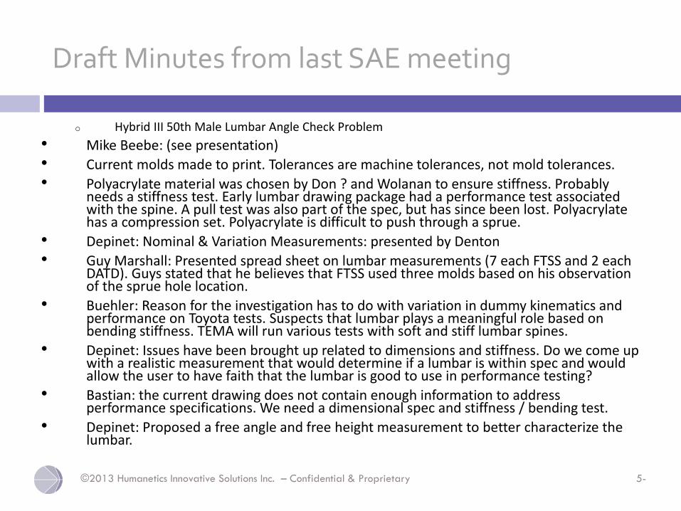
o Hybrid III 50th Male Lumbar Angle Check Problem
• Mike Beebe: (see presentation)
• Current molds made to print. Tolerances are machine tolerances, not mold tolerances.
• Polyacrylate material was chosen by Don ? and Wolanan to ensure stiffness. Probably needs a stiffness test. Early lumbar drawing package had a performance test associated with the spine. A pull test was also part of the spec, but has since been lost. Polyacrylatehas a compression set. Polyacrylate is difficult to push through a sprue.
• Depinet: Nominal & Variation Measurements: presented by Denton
• Guy Marshall: Presented spread sheet on lumbar measurements (7 each FTSS and 2 each DATD). Guys stated that he believes that FTSS used three molds based on his observation of the sprue hole location.
• Buehler: Reason for the investigation has to do with variation in dummy kinematics and performance on Toyota tests. Suspects that lumbar plays a meaningful role based on bending stiffness. TEMA will run various tests with soft and stiff lumbar spines.
• Depinet: Issues have been brought up related to dimensions and stiffness. Do we come up with a realistic measurement that would determine if a lumbar is within spec and would allow the user to have faith that the lumbar is good to use in performance testing?
• Bastian: the current drawing does not contain enough information to address performance specifications. We need a dimensional spec and stiffness / bending test.
• Depinet: Proposed a free angle and free height measurement to better characterize the lumbar.
©2013 Humanetics Innovative Solutions Inc. – Confidential & Proprietary 5-
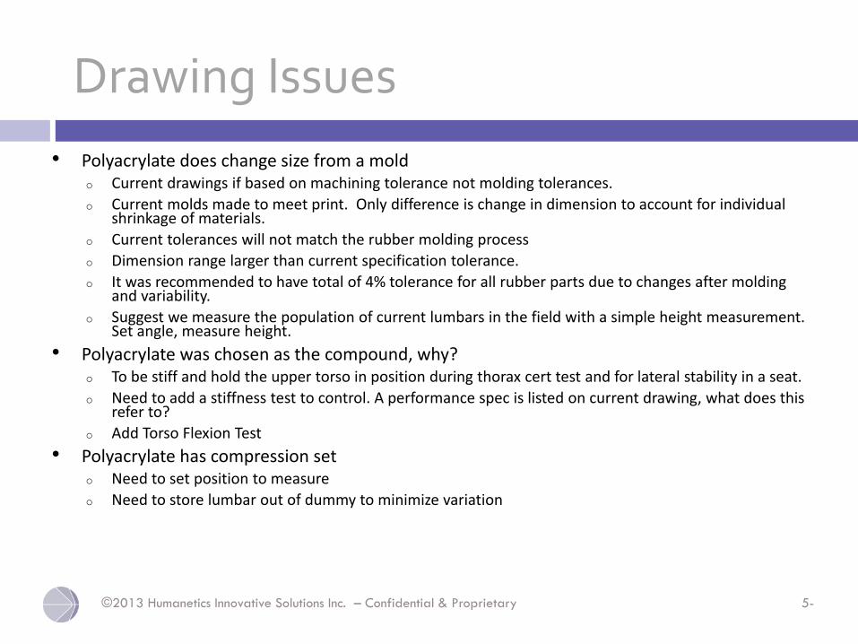
Drawing Issues
• Polyacrylate does change size from a moldo Current drawings if based on machining tolerance not molding tolerances.
o Current molds made to meet print. Only difference is change in dimension to account for individual shrinkage of materials.
o Current tolerances will not match the rubber molding process
o Dimension range larger than current specification tolerance.
o It was recommended to have total of 4% tolerance for all rubber parts due to changes after molding and variability.
o Suggest we measure the population of current lumbars in the field with a simple height measurement. Set angle, measure height.
• Polyacrylate was chosen as the compound, why? o To be stiff and hold the upper torso in position during thorax cert test and for lateral stability in a seat.
o Need to add a stiffness test to control. A performance spec is listed on current drawing, what does this refer to?
o Add Torso Flexion Test
• Polyacrylate has compression seto Need to set position to measure
o Need to store lumbar out of dummy to minimize variation
5/15/2014
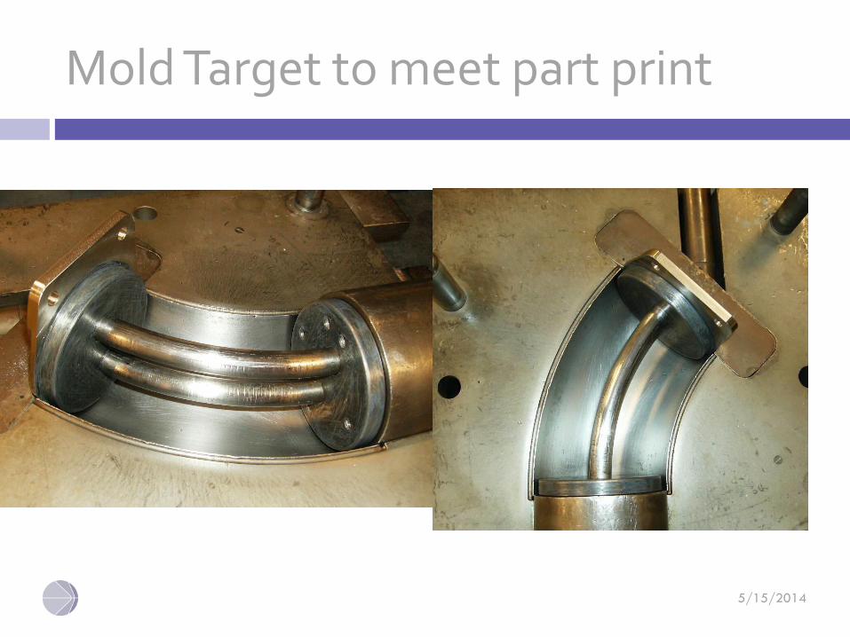
Mold Target to meet part print
©2013 Humanetics Innovative Solutions Inc. – Confidential & Proprietary 5-
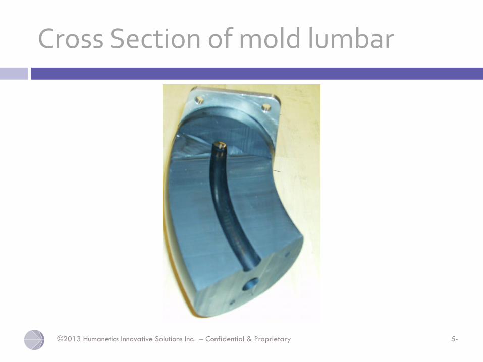
Cross Section of mold lumbar

5/15/2014
Comparison of Height and Cable Arc Length measurements & Calculations from Drawing Requirements
5/15/2014
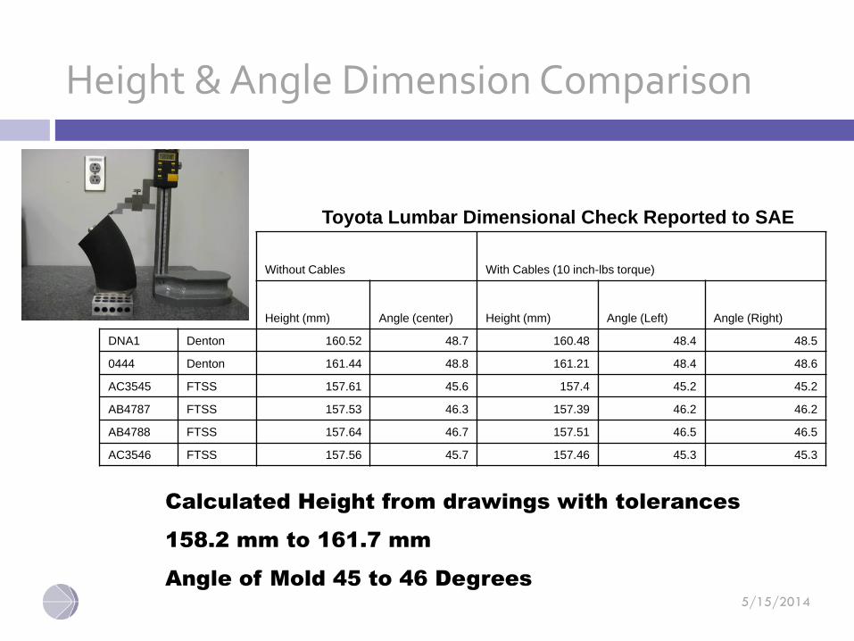
Height & Angle Dimension Comparison
Toyota Lumbar Dimensional Check Reported to SAE
Without Cables With Cables (10 inch-lbs torque)
Height (mm) Angle (center) Height (mm) Angle (Left) Angle (Right)
DNA1 Denton 160.52 48.7 160.48 48.4 48.5
0444 Denton 161.44 48.8 161.21 48.4 48.6
AC3545 FTSS 157.61 45.6 157.4 45.2 45.2
AB4787 FTSS 157.53 46.3 157.39 46.2 46.2
AB4788 FTSS 157.64 46.7 157.51 46.5 46.5
AC3546 FTSS 157.56 45.7 157.46 45.3 45.3
Calculated Height from drawings with tolerances
158.2 mm to 161.7 mm
Angle of Mold 45 to 46 Degrees
©2013 Humanetics Innovative Solutions Inc. – Confidential & Proprietary 5-
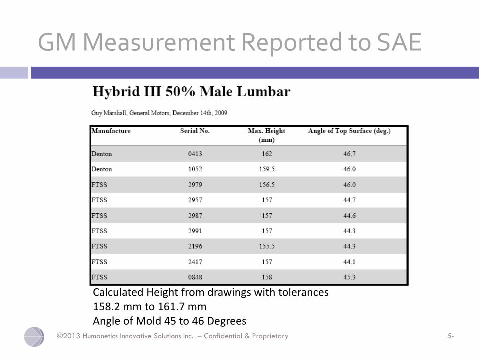
GM Measurement Reported to SAE
Calculated Height from drawings with tolerances158.2 mm to 161.7 mmAngle of Mold 45 to 46 Degrees
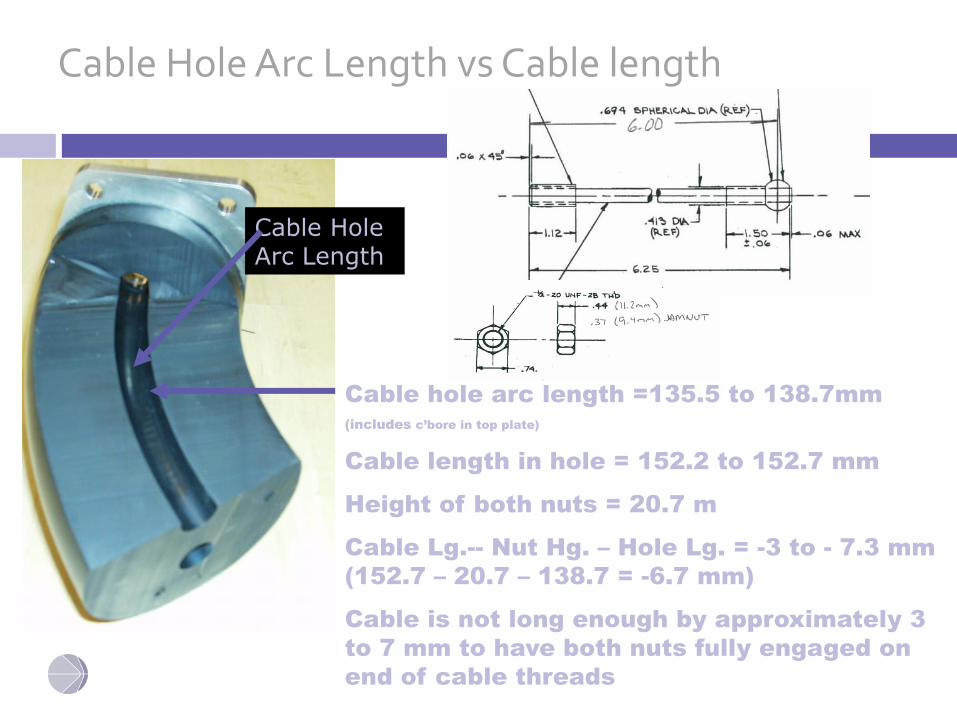
Cable Hole Arc Length vs Cable length
Cable Hole Arc Length
Cable hole arc length =135.5 to 138.7mm
(includes c’bore in top plate)
Cable length in hole = 152.2 to 152.7 mm
Height of both nuts = 20.7 m
Cable Lg.-- Nut Hg. – Hole Lg. = -3 to - 7.3 mm
(152.7 – 20.7 – 138.7 = -6.7 mm)
Cable is not long enough by approximately 3
to 7 mm to have both nuts fully engaged on
end of cable threads
5/15/2014
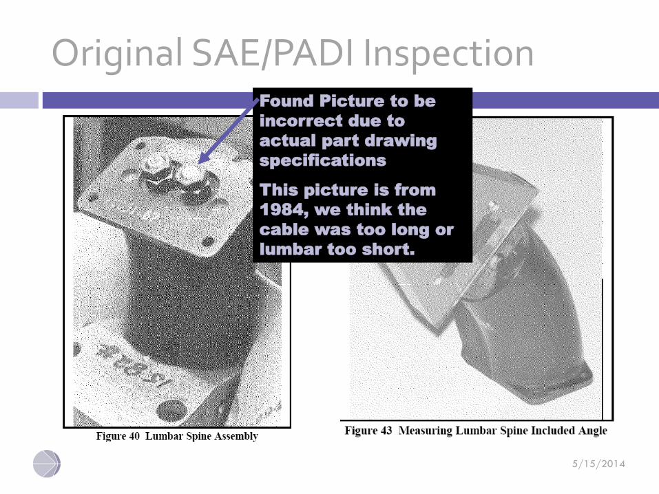
Original SAE/PADI InspectionFound Picture to be
incorrect due to
actual part drawing
specifications
This picture is from
1984, we think the
cable was too long or
lumbar too short.
5/15/2014
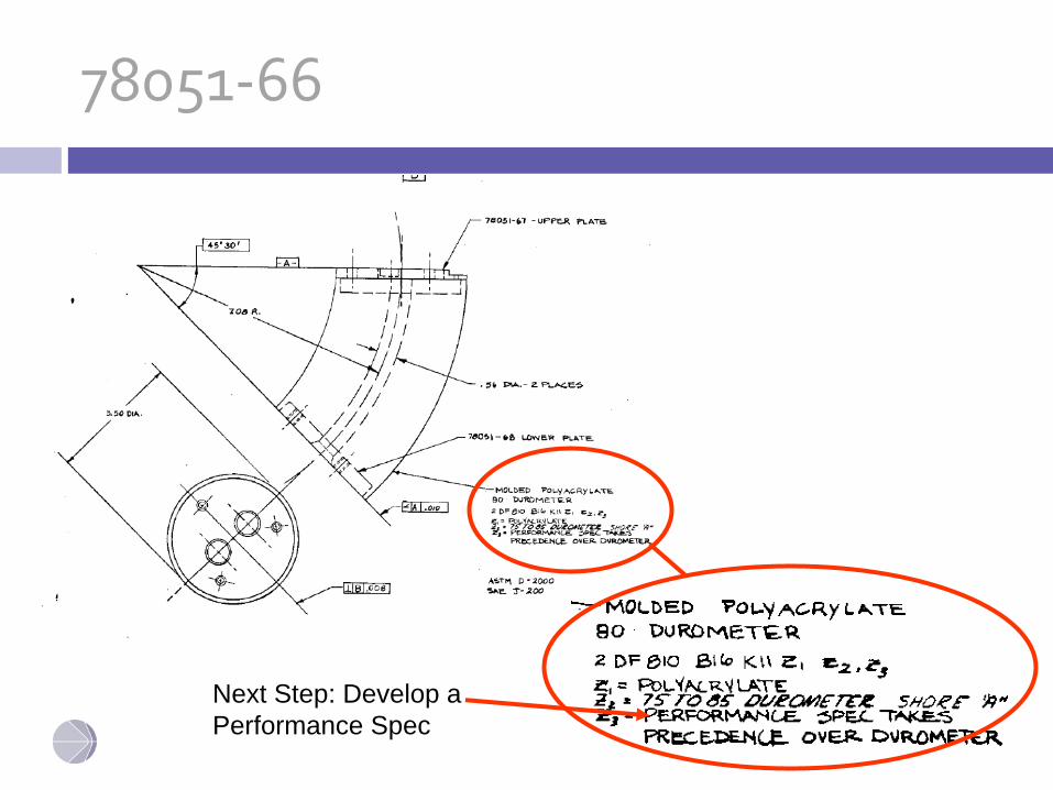
78051-66
Next Step: Develop a
Performance Spec
5/15/2014
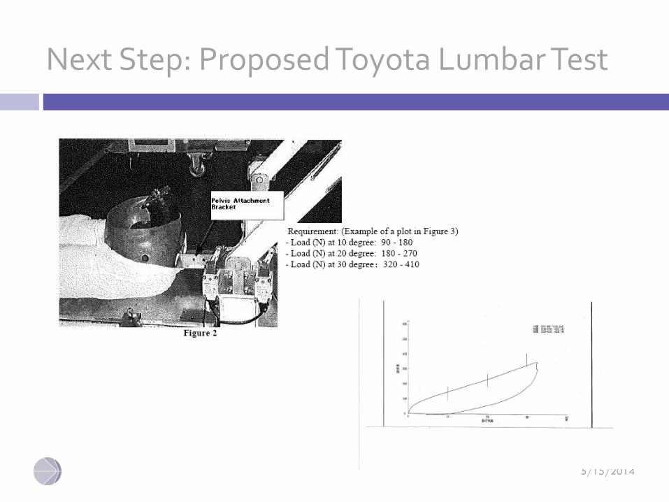
Next Step: Proposed Toyota Lumbar Test
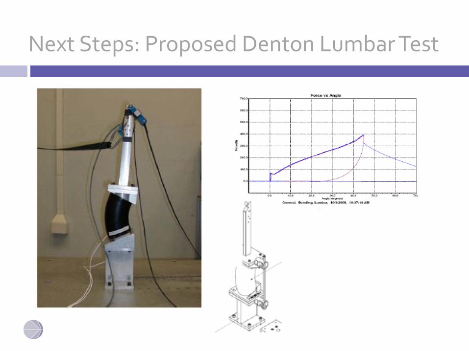
Next Steps: Proposed Denton Lumbar Test
©2013 Humanetics Innovative Solutions Inc. – Confidential & Proprietary 5-
Issues when part is removed from mold
• Variation in parts greater than tolerance on drawing.
o Rubber can change after molding
o Any bending test, storage in dummy, use, etc.. Changes shape of lumbar. This is due to compression set of the rubber.
o Need a stiffness test
o Agreed upon dimension
o Typical Physical Properties of Polymer
o Interesting comparison of Polyacrylate and two other types in compressive stress relaxation
©2013 Humanetics Innovative Solutions Inc. – Confidential & Proprietary 5-
SAE Next Steps
• Guy Marshall will put a spread sheet together, along with a few instructional points, on how to measure and record this information. Spread sheet is to be distributed to members and returned to Guy for collation.
• Buehler will measure the dimensions of the lumbar spines that he has with and without the cables to see if the cable makes a difference in the angle or height.
• Buehler: Presented data on lumbar bending test – which included the test setup and procedures. TEMA measured the initial angle and load at 10, 20, and 30 degrees. Fixture uses a quick release and they measure return angle.
• Depinet: Do we need a component test and a system (torso flexion) test at this time for the lumbar? Need to determine if this part is repeatable. Also need to measure the pelvis to see if it is moving during the pull test. Buehler volunteered to check this.
• Pietsch: would prefer to look at the lumbar first before we add tests to the portfolio of tests already required.
• Beebe: develop and run a quasi-static test before investigating other tests. Run the Toyota test for now as a baseline. Supported by Pietsch, but eliminate the pelvis from the test.
• Bastian: For now, let’s go ahead and use the hardware specified by Toyota since everyone has most of the hardware in their lab now. Bastian needs to check on the neck bracket to see if there is a drawing. If so, make it available.
• Buehler: volunteered to run additional tests to lock down the test details. TEMA has a procedure written by FTSS (translated from Japanese) that can be made available. It will be distributed so that others can try it and provide feedback.
• Beebe: Recommended that DATD and FTSS work with Toyota to nail down the procedure and get a round robin test going with FTSS and Denton lumbar spines.
©2013 Humanetics Innovative Solutions Inc. – Confidential & Proprietary 5-
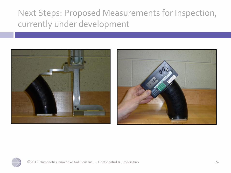
Next Steps: Proposed Measurements for Inspection, currently under development
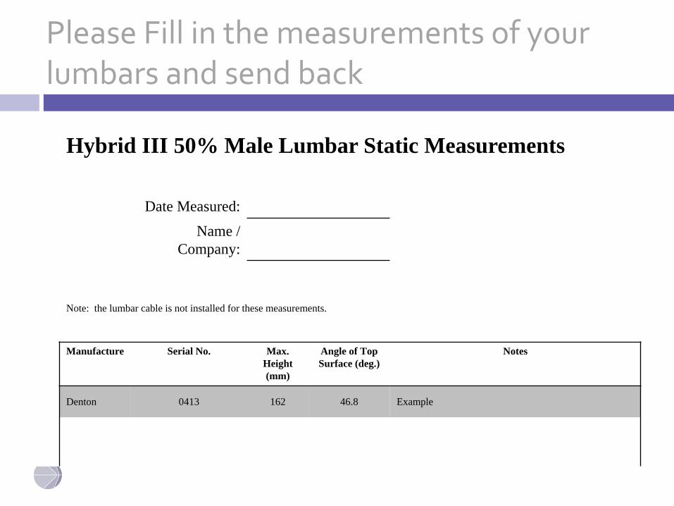
Please Fill in the measurements of your lumbars and send back
Hybrid III 50% Male Lumbar Static Measurements
Date Measured:
Name /
Company:
Note: the lumbar cable is not installed for these measurements.
Manufacture Serial No. Max.
Height
(mm)
Angle of Top
Surface (deg.)
Notes
Denton 0413 162 46.8 Example
©2013 Humanetics Innovative Solutions Inc. – Confidential & Proprietary 5-
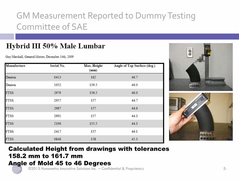
GM Measurement Reported to Dummy Testing Committee of SAE
Calculated Height from drawings with tolerances
158.2 mm to 161.7 mm
Angle of Mold 45 to 46 Degrees
©2013 Humanetics Innovative Solutions Inc. – Confidential & Proprietary 5-
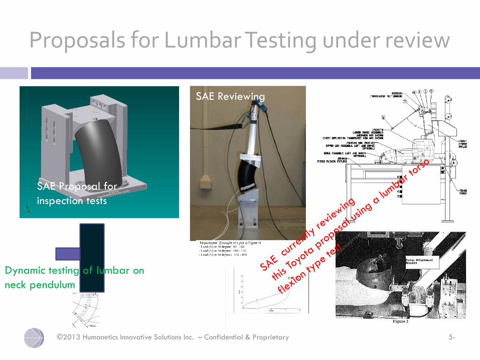
Proposals for Lumbar Testing under review
SAE Proposal for
inspection tests
SAE Reviewing
Dynamic testing of lumbar on
neck pendulum
5/15/2014
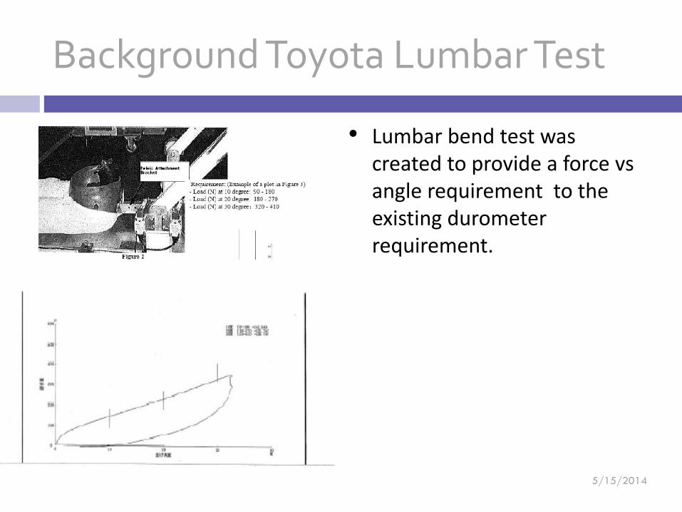
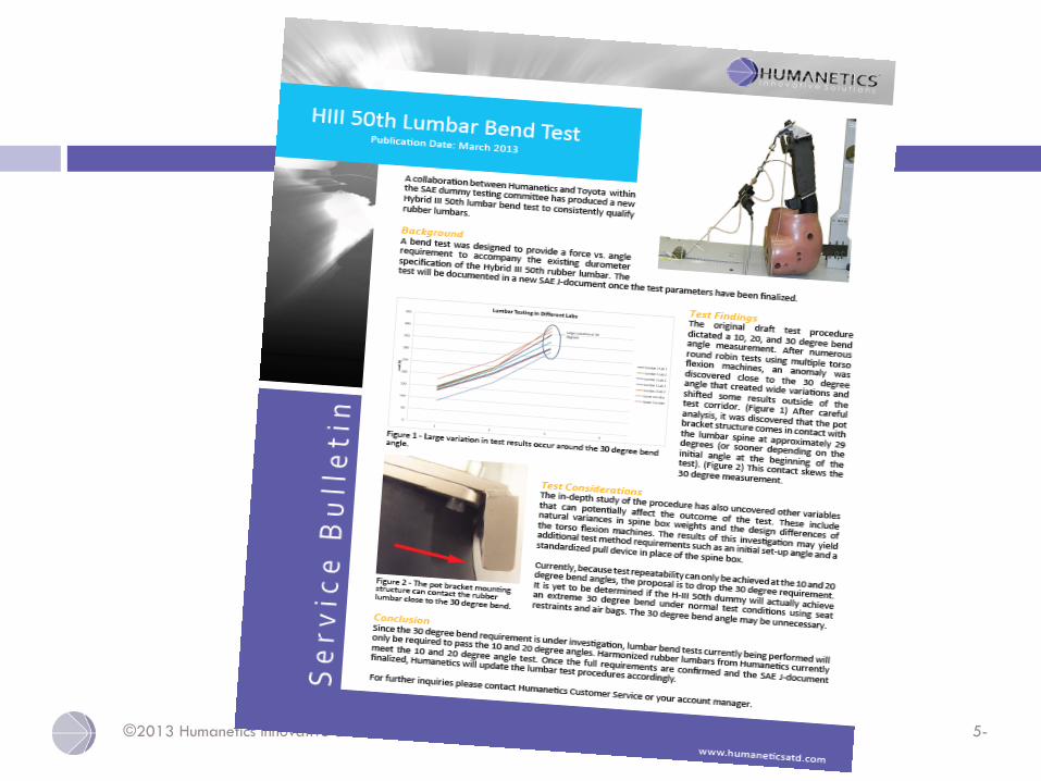
Background Toyota Lumbar Test
• Lumbar bend test was created to provide a force vsangle requirement to the existing durometerrequirement.
5/15/2014
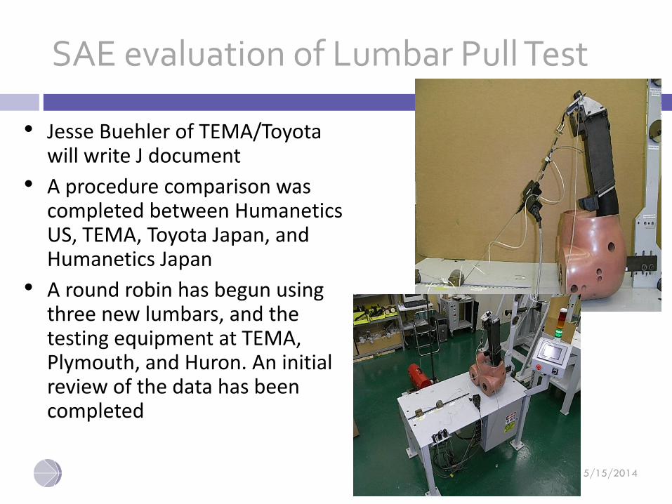
SAE evaluation of Lumbar Pull Test
• Jesse Buehler of TEMA/Toyota will write J document
• A procedure comparison was completed between HumaneticsUS, TEMA, Toyota Japan, and Humanetics Japan
• A round robin has begun using three new lumbars, and the testing equipment at TEMA, Plymouth, and Huron. An initial review of the data has been completed
5/15/2014
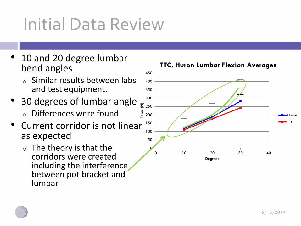
Initial Data Review
• 10 and 20 degree lumbar bend angleso Similar results between labs
and test equipment.
• 30 degrees of lumbar angleo Differences were found
• Current corridor is not linear as expected o The theory is that the
corridors were created including the interference between pot bracket and lumbar
0
50
100
150
200
250
300
350
400
450
0 10 20 30 40
Forc
e (
N)
Degrees
TTC, Huron Lumbar Flexion Averages
Huron
TTC
5/15/2014
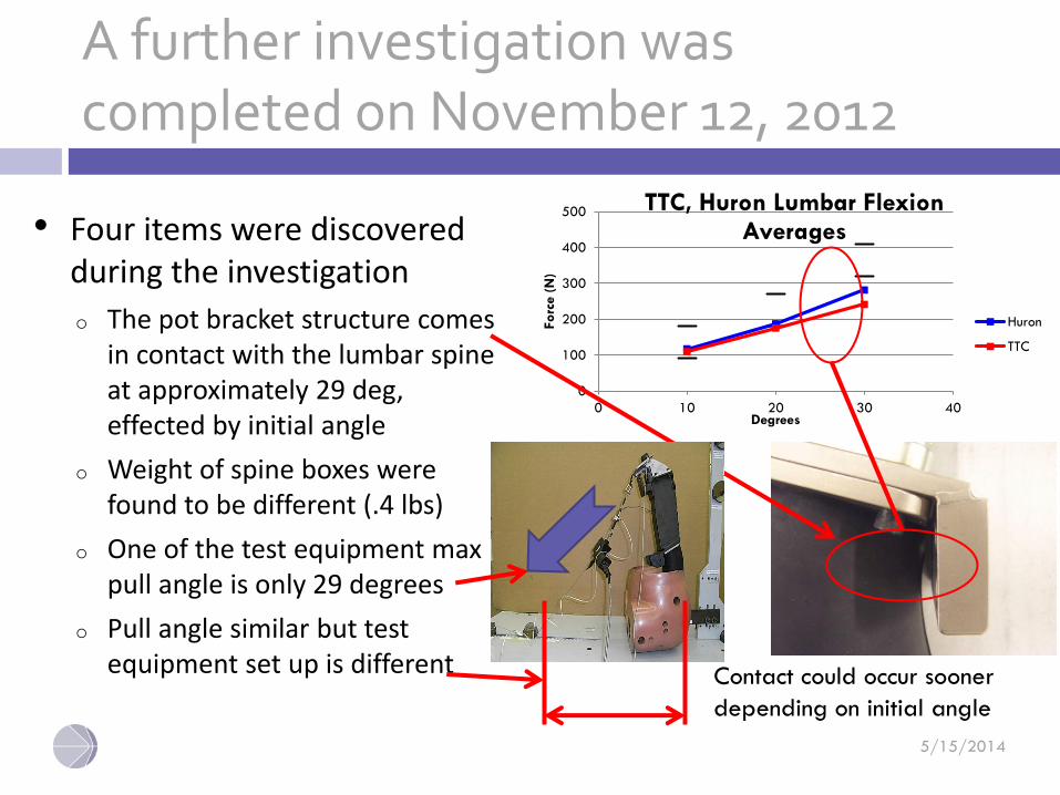
A further investigation was completed on November 12, 2012
• Four items were discovered during the investigation
o The pot bracket structure comes in contact with the lumbar spine at approximately 29 deg, effected by initial angle
o Weight of spine boxes were found to be different (.4 lbs)
o One of the test equipment max pull angle is only 29 degrees
o Pull angle similar but test equipment set up is different
0
100
200
300
400
500
0 10 20 30 40
Forc
e (
N)
Degrees
TTC, Huron Lumbar Flexion Averages
Huron
TTC
Contact could occur sooner
depending on initial angle
©2013 Humanetics Innovative Solutions Inc. – Confidential & Proprietary 5-
5/15/2014
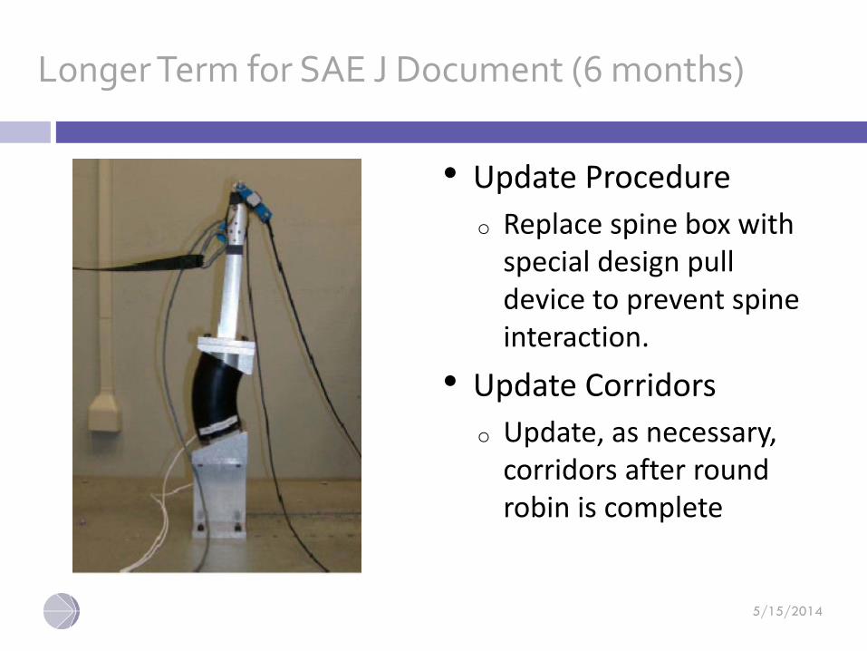
Longer Term for SAE J Document (6 months)
• Update Procedure
o Replace spine box with special design pull device to prevent spine interaction.
• Update Corridors
o Update, as necessary, corridors after round robin is complete
©2013 Humanetics Innovative Solutions Inc. – Confidential & Proprietary 5-
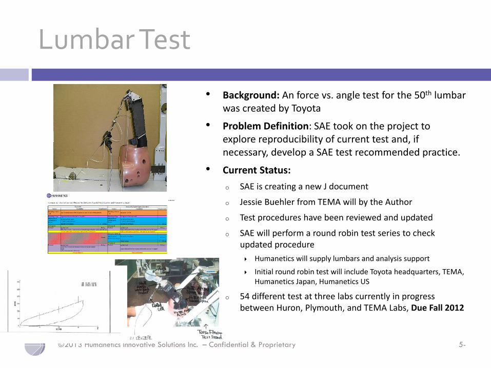
Lumbar Test
• Background: An force vs. angle test for the 50th lumbar was created by Toyota
• Problem Definition: SAE took on the project to explore reproducibility of current test and, if necessary, develop a SAE test recommended practice.
• Current Status:
o SAE is creating a new J document
o Jessie Buehler from TEMA will by the Author
o Test procedures have been reviewed and updated
o SAE will perform a round robin test series to check updated procedure
Humanetics will supply lumbars and analysis support
Initial round robin test will include Toyota headquarters, TEMA, Humanetics Japan, Humanetics US
o 54 different test at three labs currently in progress between Huron, Plymouth, and TEMA Labs, Due Fall 2012
©2013 Humanetics Innovative Solutions Inc. – Confidential & Proprietary 5-
Conclusion
• Humanetics to draft Lumbar test for SAE and will send out for vote
©2013 Humanetics Innovative Solutions Inc. – Confidential & Proprietary 5-
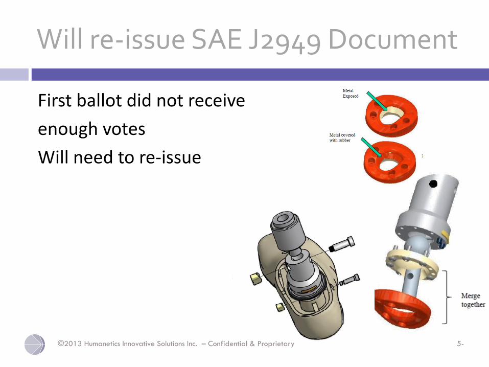
Will re-issue SAE J2949 Document
First ballot did not receive
enough votes
Will need to re-issue
©2013 Humanetics Innovative Solutions Inc. – Confidential & Proprietary 5-
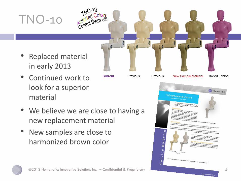
TNO-10
• We believe we are close to having a new replacement material
• New samples are close to harmonized brown color
• Replaced material in early 2013
• Continued work to look for a superior material
©2013 Humanetics Innovative Solutions Inc. – Confidential & Proprietary 5-
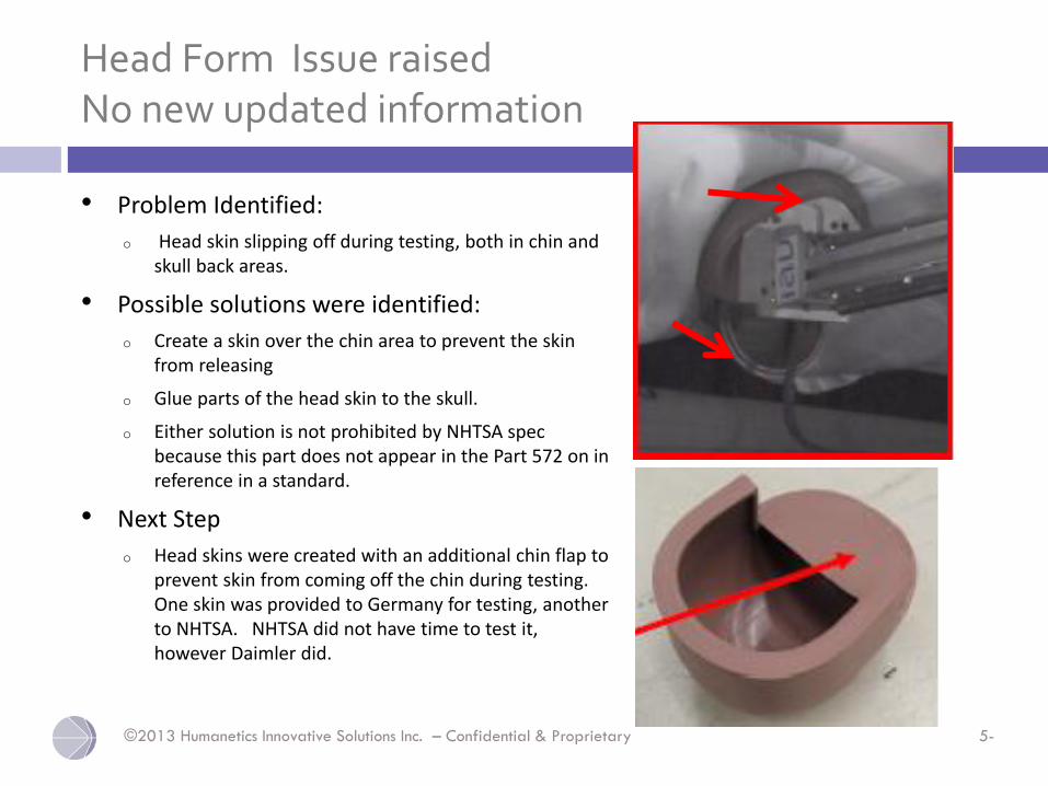
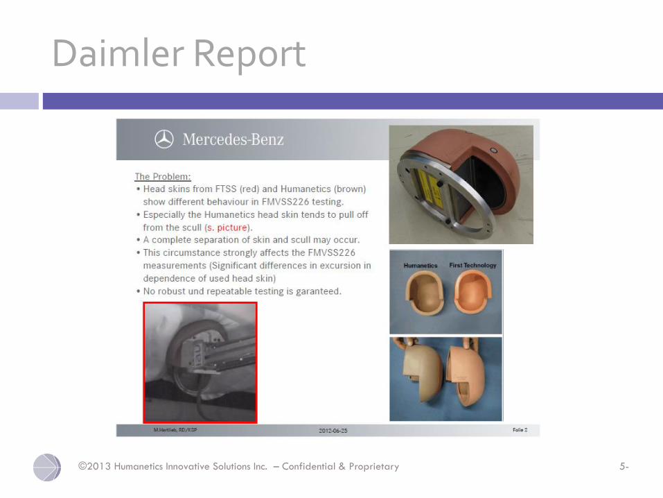
Head Form Issue raisedNo new updated information
• Problem Identified:
o Head skin slipping off during testing, both in chin and skull back areas.
• Possible solutions were identified:
o Create a skin over the chin area to prevent the skin from releasing
o Glue parts of the head skin to the skull.
o Either solution is not prohibited by NHTSA spec because this part does not appear in the Part 572 on in reference in a standard.
• Next Step
o Head skins were created with an additional chin flap to prevent skin from coming off the chin during testing. One skin was provided to Germany for testing, another to NHTSA. NHTSA did not have time to test it, however Daimler did.
©2013 Humanetics Innovative Solutions Inc. – Confidential & Proprietary 5-
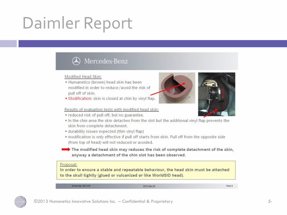
Daimler Report
©2013 Humanetics Innovative Solutions Inc. – Confidential & Proprietary 5-
Daimler Report
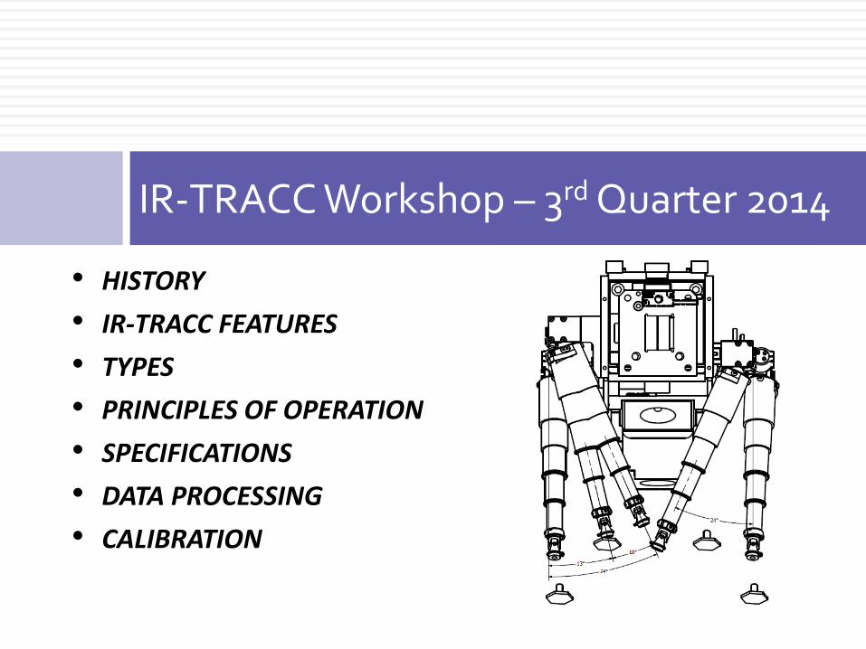
IR-TRACC Workshop – 3rd Quarter 2014
• HISTORY
• IR-TRACC FEATURES
• TYPES
• PRINCIPLES OF OPERATION
• SPECIFICATIONS
• DATA PROCESSING
• CALIBRATION
©2013 Humanetics Innovative Solutions Inc. – Confidential & Proprietary 5-
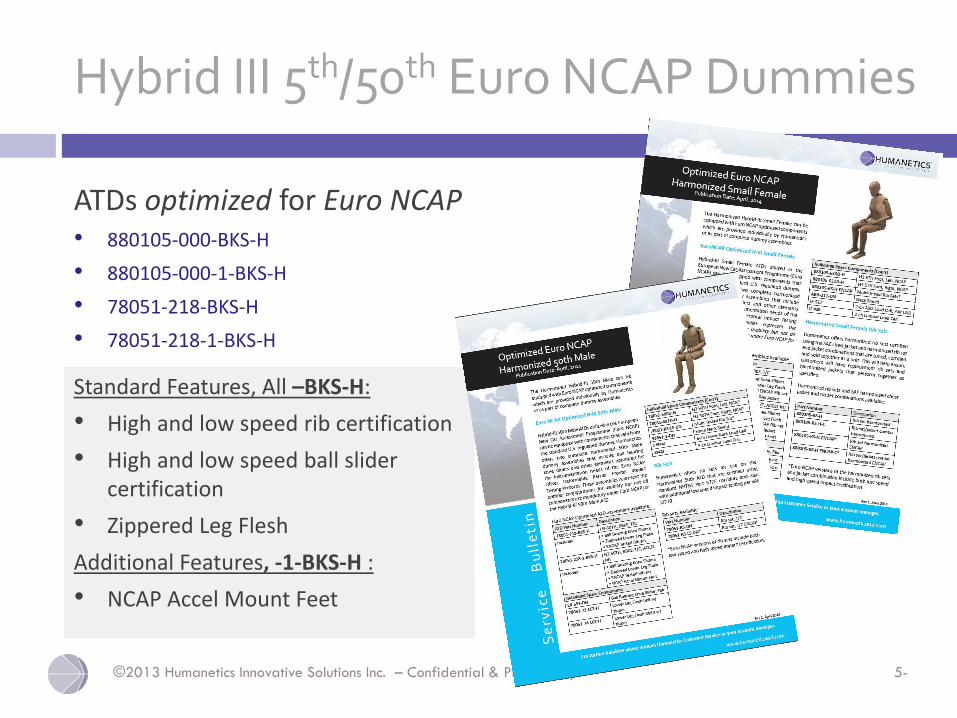
Hybrid III 5th/50th Euro NCAP Dummies
ATDs optimized for Euro NCAP • 880105-000-BKS-H
• 880105-000-1-BKS-H
• 78051-218-BKS-H
• 78051-218-1-BKS-H
Standard Features, All –BKS-H:
• High and low speed rib certification
• High and low speed ball slider certification
• Zippered Leg Flesh
Additional Features, -1-BKS-H :
• NCAP Accel Mount Feet
©2013 Humanetics Innovative Solutions Inc. – Confidential & Proprietary 5-
H Standard
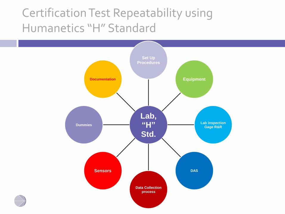
Certification Test Repeatability using Humanetics “H” Standard
Lab, “H” Std.
Set Up Procedures
Equipment
Lab inspectionGage R&R
DAS
Data Collection process
Sensors
Dummies
Documentation

DRAFT H STANDARD
©2013 Humanetics Innovative Solutions Inc. – Confidential & Proprietary 5-
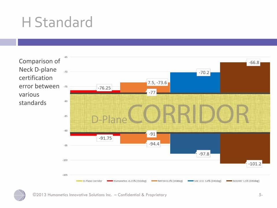
H Standard
Comparison of Neck D-plane certification error between various standards
WS50 SINGLE RIB CERTIFICATION
Oct 2013
©2013 Humanetics Innovative Solutions Inc. – Confidential & Proprietary 5-
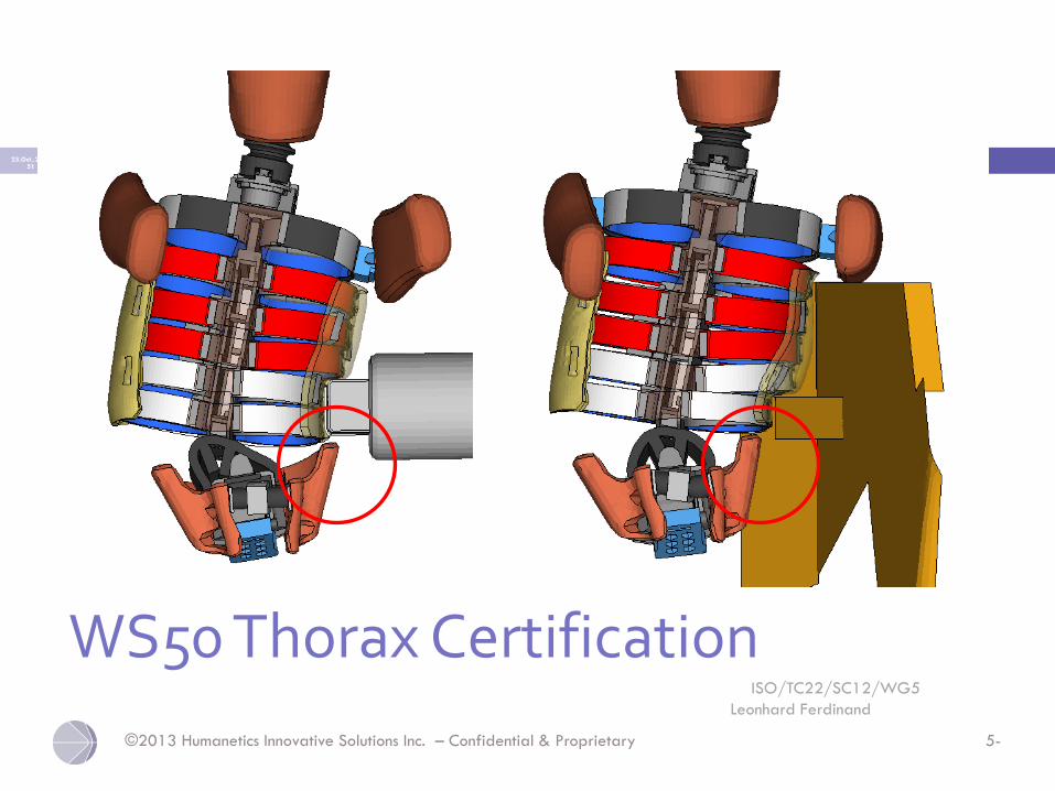
WS50 Thorax CertificationISO/TC22/SC12/WG5
Leonhard Ferdinand
23.Oct..2012 51
©2013 Humanetics Innovative Solutions Inc. – Confidential & Proprietary 5-
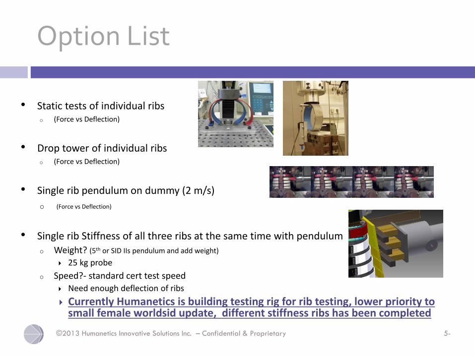
Option List
• Static tests of individual ribs o (Force vs Deflection)
• Drop tower of individual ribs o (Force vs Deflection)
• Single rib pendulum on dummy (2 m/s)
o (Force vs Deflection)
• Single rib Stiffness of all three ribs at the same time with pendulumo Weight? (5th or SID IIs pendulum and add weight)
25 kg probe
o Speed?- standard cert test speed Need enough deflection of ribs
Currently Humanetics is building testing rig for rib testing, lower priority to small female worldsid update, different stiffness ribs has been completed
©2013 Humanetics Innovative Solutions Inc. – Confidential & Proprietary 5-
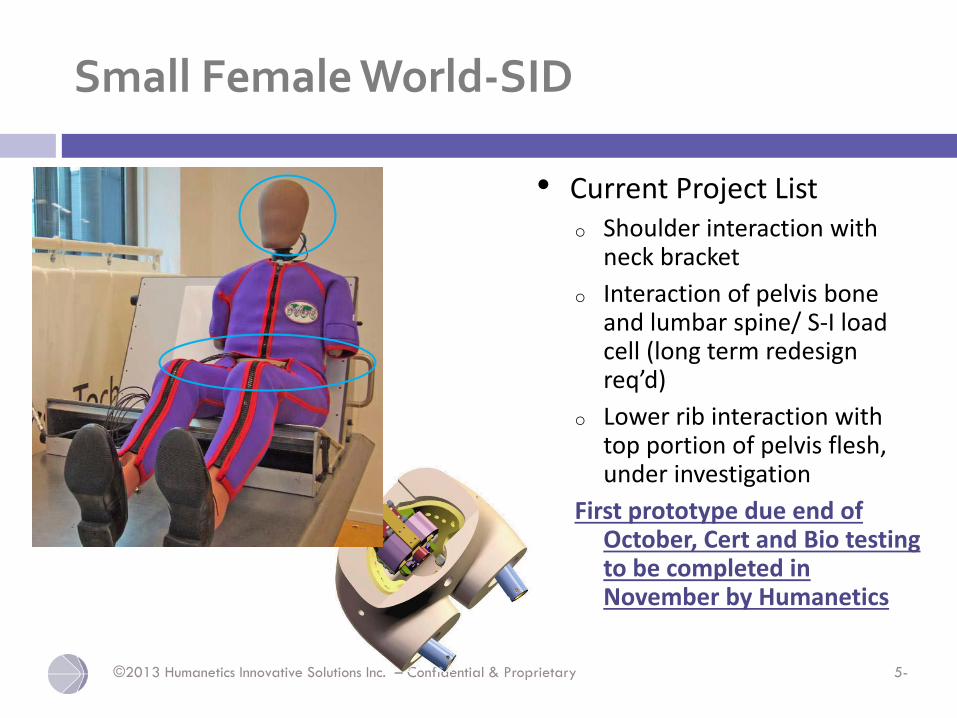
Small Female World-SID
• Current Project Listo Shoulder interaction with
neck bracket
o Interaction of pelvis bone and lumbar spine/ S-I load cell (long term redesign req’d)
o Lower rib interaction with top portion of pelvis flesh, under investigation
First prototype due end of October, Cert and Bio testing to be completed in November by Humanetics
WORLDSID 5TH DESIGN UPDATESPRESENTED TO GTR TEG
prepared by: Paul Depinet & Ashwin Mathews5/6/14
©2013 Humanetics Innovative Solutions Inc. – Confidential & Proprietary 5-
Shoulder Status
• Neck bracket fito Carefully re-examined tolerance stackup
o Redid drawings with GD&T calloutsGuarantee parts will always fit if to tolerance
› Evaluating supplier capable of checking accurately enough
o Neck brackets are on order
• Timingo As soon as one set is in and fits correctly, dynamic
testing will begin
o Once we get remainder of sets, strength validation testing will be completed
©2013 Humanetics Innovative Solutions Inc. – Confidential & Proprietary 5-
Pelvis Testing – current status
• Have cables to collect all load cell channels
• Pelvis processo Developed material & process that should be
reproducible
• Testingo Completed matrix of varying stiffness parts
o Completed testing with 2 of 3 new pelvises
o Looked at contacts using chalk with softest parts
o Testing up to this point with original setup
o Using scaled corridor from B. Donnelly
©2013 Humanetics Innovative Solutions Inc. – Confidential & Proprietary 5-
Pelvis Testing – Next Steps
• Test 3rd pelvis
• Pick set of parts for next stepso Can predict response as soon as we have 3rd pelvis
o Will shoot for middle of corridor
• Try new setup suggested at last meetingo Torso upright as possible
o Maintain relationship between torso and pelvisDon’t come so far forward that probe contacts table (allow
1 cm)
o Run 6 tests to compare to original setup
©2013 Humanetics Innovative Solutions Inc. – Confidential & Proprietary 5-
Pelvis Testing – Next Steps
• Run tests over widest velocity range we can achieve
o 4.5 up to 7.0 m/s, will attempt up to 10 m/s
o Use contact switches and chalk to look for contacts
• Reassess selection of parts
o Did contact occur at high velocity
o How did biofidelity look at high velocity
o Possible try lower or higher stiffness parts
©2013 Humanetics Innovative Solutions Inc. – Confidential & Proprietary 5-
Pelvis Testing – Next Steps
• Run certification pendulumo Use contact switches & collect all pelvis channels and T12
acceleration & rotation
o Use bench method 6.7 m/s
o Run tests at velocities as high as we can achieveTry to get 5, 6, 6.7, 7, 7.5, 8.0, 8.5, 9.0, 9.5, 10.0
Use velocity range to look for if/when contacts start to occur
Run 25 repeat tests at 7.5 m/s if contact occurs above this to look for durability (25% increase in energy)
Run 10 repeat tests at 8.2 m/s if contact occurs above this to look for durability (50% increase in energy)
o Repeat 6.7 m/s tests to see if performance has changed
HUMANETICS INNOVATIVE SOLUTIONS, INC.
THOR ATD
©2013 Humanetics Innovative Solutions Inc. – Confidential & Proprietary 5-
Dummy Development
In 2011 NHTSA contracted Humanetics to develop a mod kit
add-on package intended to improve biofidelity,
anthropometry, durability, and usability of existing THOR-NT
ATDs. The project included:
1. Development of a mod kit add-on package for existing
THOR-NT dummies
2. Development and fabrication of a new fully updated THOR-
NT (also known as THOR-M)
3. Fabrication and installation of mod kits on existing NHTSA
THOR-NT dummies.
©2013 Humanetics Innovative Solutions Inc. – Confidential & Proprietary 5-
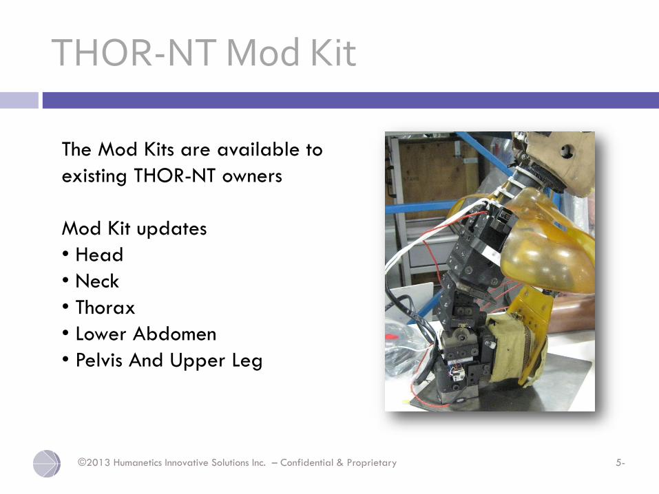
THOR-NT Mod Kit
The Mod Kits are available to
existing THOR-NT owners
Mod Kit updates
• Head
• Neck
• Thorax
• Lower Abdomen
• Pelvis And Upper Leg
©2013 Humanetics Innovative Solutions Inc. – Confidential & Proprietary 5-
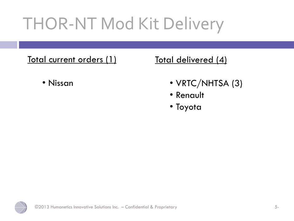
THOR-NT Mod Kit Delivery
Total delivered (4)
• VRTC/NHTSA (3)
• Renault
• Toyota
Total current orders (1)
• Nissan
©2013 Humanetics Innovative Solutions Inc. – Confidential & Proprietary 5-
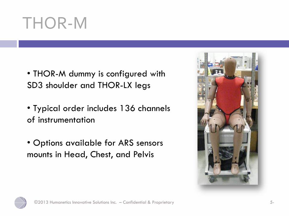
THOR-M
• THOR-M dummy is configured with
SD3 shoulder and THOR-LX legs
• Typical order includes 136 channels
of instrumentation
• Options available for ARS sensors
mounts in Head, Chest, and Pelvis
©2013 Humanetics Innovative Solutions Inc. – Confidential & Proprietary 5-
THOR-M Delivery
Total delivered (4)
• VRTC/NHTSA (3)
• BAST
Total current orders (14)
• GM
• TEMA
• Toyota (2)
• Mazda (2)
• Nissan
• Honda (3)
• Ford (2)
• PDB
• Daimler
©2013 Humanetics Innovative Solutions Inc. – Confidential & Proprietary 5-
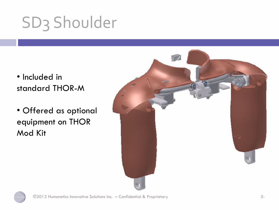
SD3 Shoulder
• Included in
standard THOR-M
• Offered as optional
equipment on THOR
Mod Kit
©2013 Humanetics Innovative Solutions Inc. – Confidential & Proprietary 5-
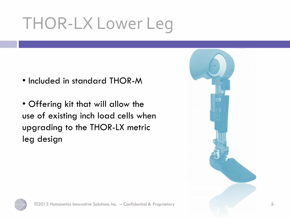
THOR-LX Lower Leg
• Included in standard THOR-M
• Offering kit that will allow the
use of existing inch load cells when
upgrading to the THOR-LX metric
leg design
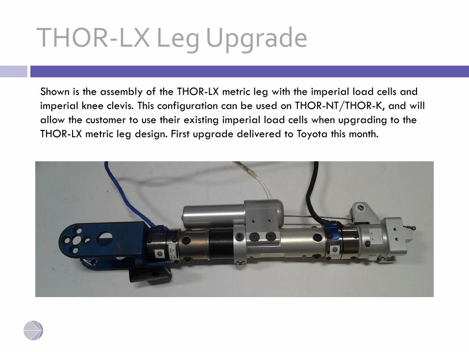
THOR-LX Leg Upgrade
Shown is the assembly of the THOR-LX metric leg with the imperial load cells and
imperial knee clevis. This configuration can be used on THOR-NT/THOR-K, and will
allow the customer to use their existing imperial load cells when upgrading to the
THOR-LX metric leg design. First upgrade delivered to Toyota this month.
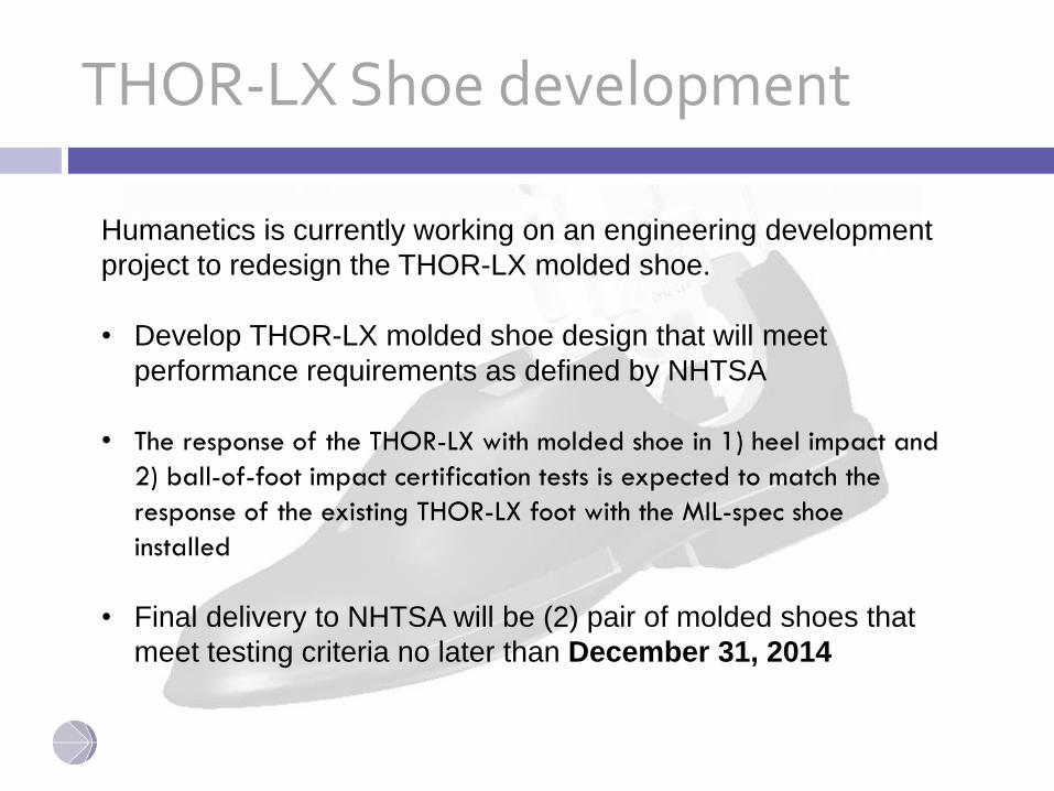
THOR-LX Shoe development
Humanetics is currently working on an engineering development
project to redesign the THOR-LX molded shoe.
• Develop THOR-LX molded shoe design that will meet
performance requirements as defined by NHTSA
• The response of the THOR-LX with molded shoe in 1) heel impact and
2) ball-of-foot impact certification tests is expected to match the
response of the existing THOR-LX foot with the MIL-spec shoe
installed
• Final delivery to NHTSA will be (2) pair of molded shoes that
meet testing criteria no later than December 31, 2014
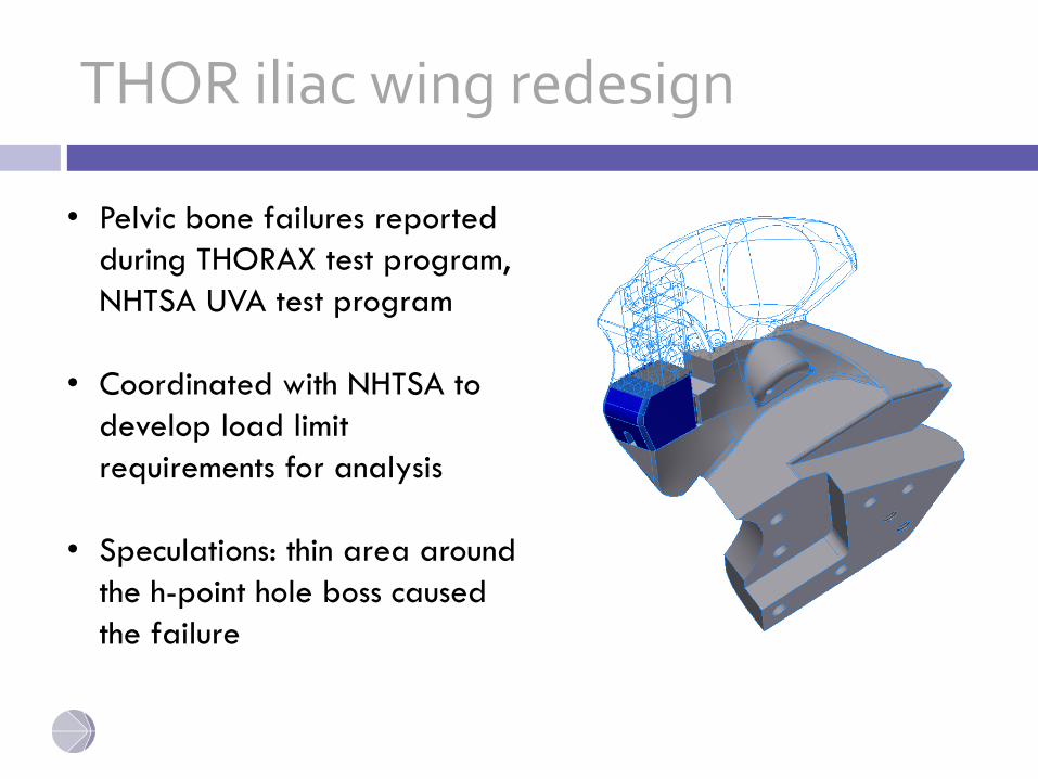
THOR iliac wing redesign
• Pelvic bone failures reported
during THORAX test program,
NHTSA UVA test program
• Coordinated with NHTSA to
develop load limit
requirements for analysis
• Speculations: thin area around
the h-point hole boss caused
the failure
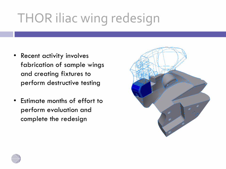
THOR iliac wing redesign
• Recent activity involves
fabrication of sample wings
and creating fixtures to
perform destructive testing
• Estimate months of effort to
perform evaluation and
complete the redesign
THOR-M Certification
• Heavy engineering focus on dummy certification, the Humanetics test team is currently working to:
o Establish preliminary certification corridorso Finalize certification test processeso Train additional test technicianso Develop certification test software o Develop certification test equipment

Q3s Update
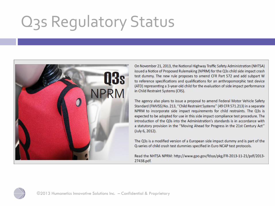
Q3s Regulatory Status
©2013 Humanetics Innovative Solutions Inc. – Confidential & Proprietary
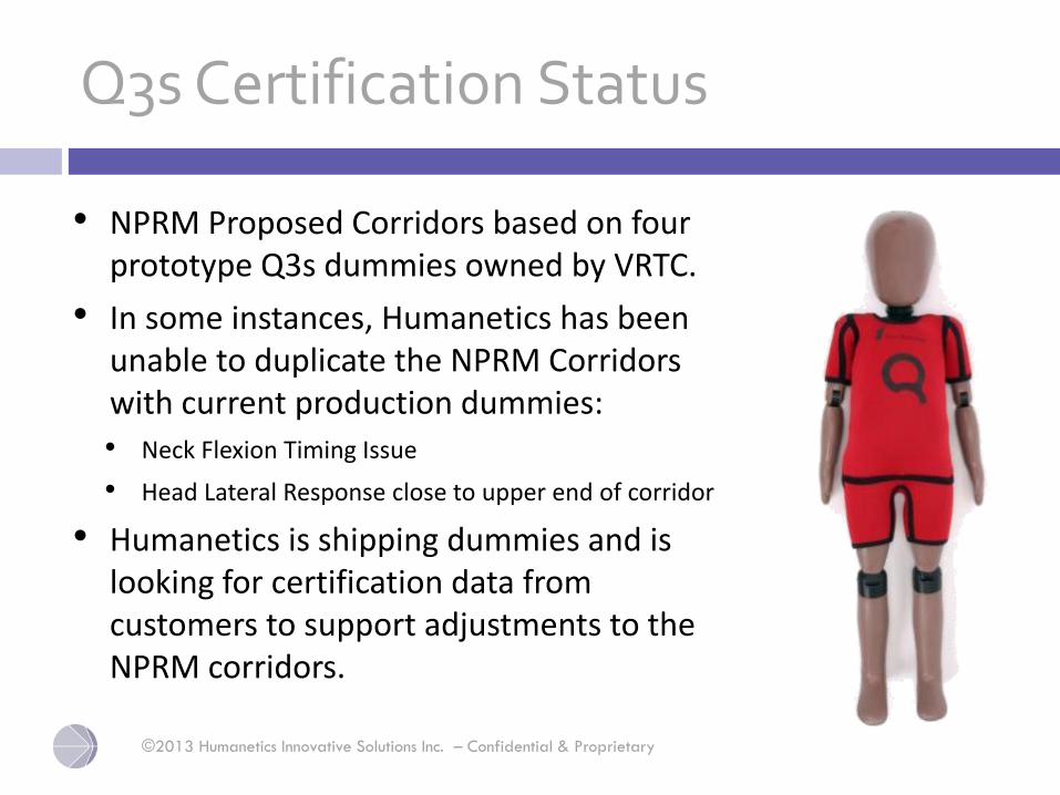
Q3s Certification Status
• NPRM Proposed Corridors based on four prototype Q3s dummies owned by VRTC.
• In some instances, Humanetics has been unable to duplicate the NPRM Corridors with current production dummies:
• Neck Flexion Timing Issue
• Head Lateral Response close to upper end of corridor
• Humanetics is shipping dummies and is looking for certification data from customers to support adjustments to the NPRM corridors.
©2013 Humanetics Innovative Solutions Inc. – Confidential & Proprietary
©2013 Humanetics Innovative Solutions Inc. – Confidential & Proprietary 5-
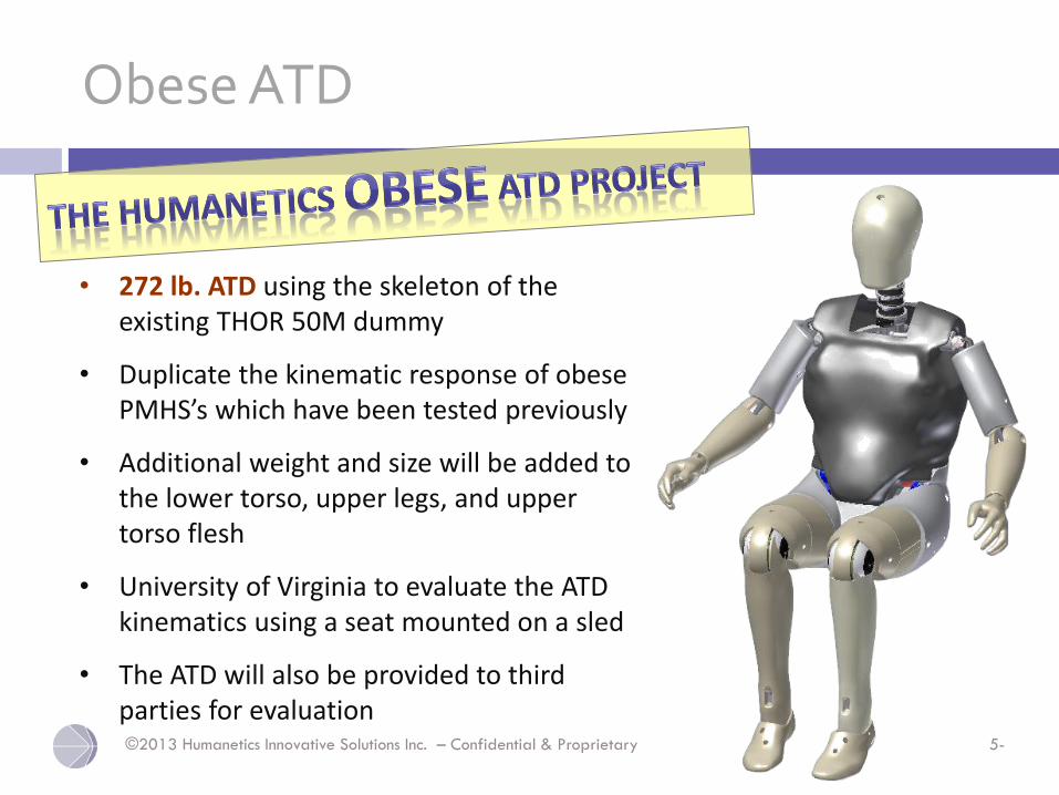
Obese ATD
• 272 lb. ATD using the skeleton of the existing THOR 50M dummy
• Duplicate the kinematic response of obese PMHS’s which have been tested previously
• Additional weight and size will be added to the lower torso, upper legs, and upper torso flesh
• University of Virginia to evaluate the ATD kinematics using a seat mounted on a sled
• The ATD will also be provided to third parties for evaluation

Scaling THOR to Obese
165 lbs. 273 lbs.
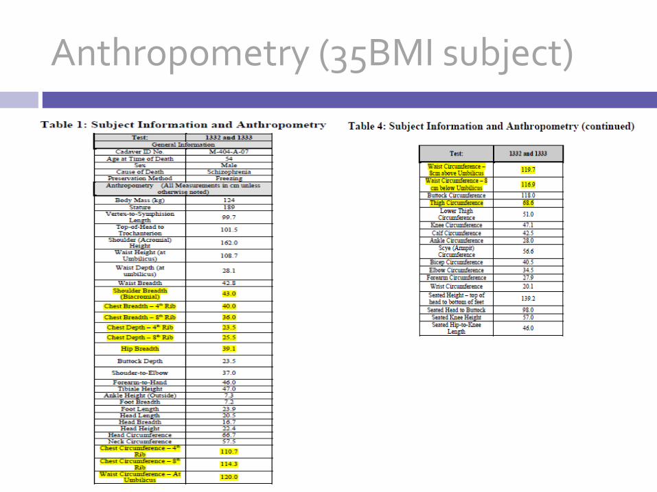
Anthropometry (35BMI subject)
5/15/2014
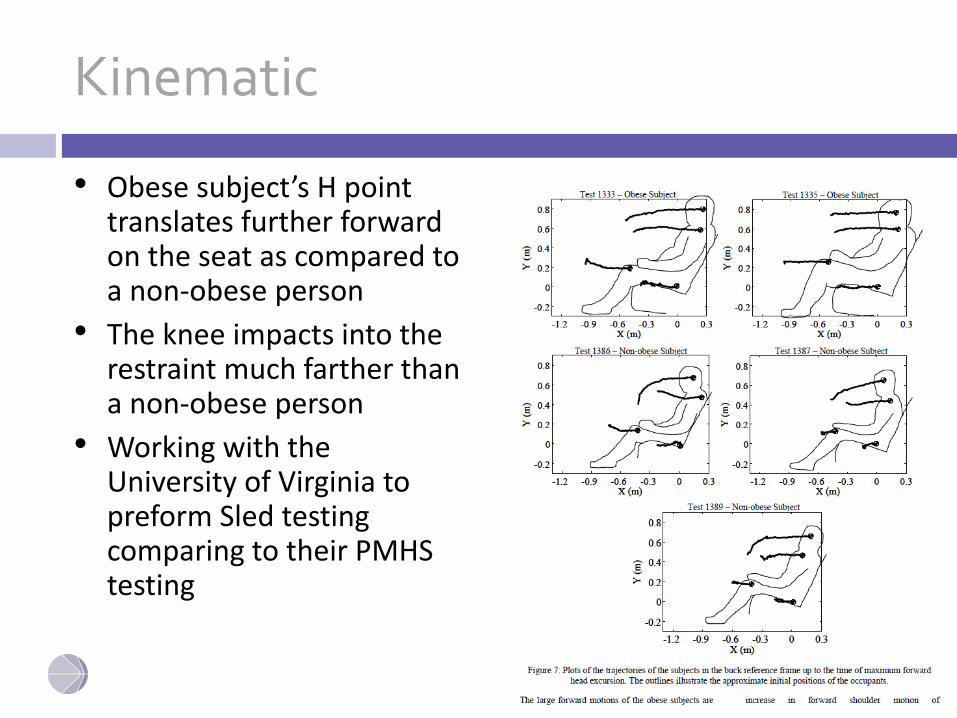
Kinematic
• Obese subject’s H point translates further forward on the seat as compared to a non-obese person
• The knee impacts into the restraint much farther than a non-obese person
• Working with the University of Virginia to preform Sled testing comparing to their PMHS testing
5/15/2014
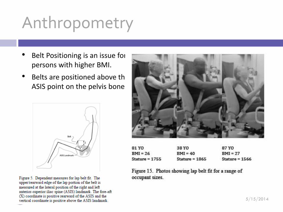
Anthropometry
• Belt Positioning is an issue for persons with higher BMI.
• Belts are positioned above the ASIS point on the pelvis bone.

The ability to have the correct regional
abdominal stiffness, intrusion measurement of the
abdominal organs, and loading patterns in the
thorax in motor vehicle crash conditions is
important for assessing head-neck loads, brain,
thorax, and abdominal injuries. Current ATD’s do
not have all the components necessary to measure
regional abdominal organ loadings necessary in
new types of crash test procedures such as
offsets. A proper thorax regional stiffness using
the proper shaped and stiffness organs in the
abdominal cavity covered with a muscle and fat
layer are the items described in this presentation.
As part of the development for these new
platforms, the development of new biofidelity
corridors and injury criterion will be completed.
Humanetics Advanced Dummy Organs (HADO)
ATD Technical Advisory Group
May 15, 2014
Thank You for your attention
© 2014 Humanetics Innovative Solutions, Inc.
This presentation is the proprietary property of Humanetics Innovative Solutions, Inc; a registered company in Plymouth, Michigan, USA. The report includes confidential information. Disclosure, use, copying, or distribution of this information without the written authorization of Humanetics Innovative Solutions is prohibited.