Embed Size (px)
Citation preview
IEEE 802.16-17-0006-03-000s
Project IEEE 802.16 Broadband Wireless Access Working Group <http://ieee802.org/16>
Title IEEE 802.16s Approved System Description Document
Date Submitted
2017-07-11 Revised 2017-08-14
Source(s) GRIDMAN Task Group Voice:
E-mail:
Re: GRIDMAN Task Group: Narrowband Channel
Abstract Approved system requirements document
Purpose System Description Document
NoticeThis document does not represent the agreed views of the IEEE 802.16 Working Group or any of its subgroups. It represents only the views of the participants listed in the “Source(s)” field above. It is offered as a basis for discussion. It is not binding on the contributor(s), who reserve(s) the right to add, amend or withdraw material contained herein.
Copyright Policy
The contributor is familiar with the IEEE-SA Copyright Policy <http://standards.ieee.org/IPR/copyrightpolicy.html>.
Patent Policy
The contributor is familiar with the IEEE-SA Patent Policy and Procedures:<http://standards.ieee.org/guides/bylaws/sect6-7.html#6> and <rmation is located at <http://standards.ieee.org/board/pat/pat-material.html> and <http://standards.ieee.org/board/pat>.

IEEE 802.16-17-0006-03-000s
IEEE 802.16s System Description Document
August 14, 2017
IEEE 802.16-17-0006-03-000s
IntroductionThis document describes the technical approach for IEEE 802.16 operation in channels less than 1.25 MHz bandwidth.
PAR Scope (From 802.16-16-0038-00-000s):
This project specifies WirelessMAN-OFDMA TDD operation in exclusively-licensed spectrum with channel bandwidth from 100 kHz up to 1.25 MHz1, including 1 MHz explicitly. The amendment will target operation in the 700 MHz band but will also support operation in other VHF/UHF bands. The project amends Clause 12 of IEEE Std 802.16, adding a new system profile and amending other clauses as required to support the narrower channel bandwidths. The range and data rate supported by the added profile are commensurate with those of the base standard, as scaled by the reduced channel bandwidth.
The italicized phrase is the reasoning behind the section for MAC changes related to improving efficiency, which is necessary to meet SRD requirements in narrower channel bandwidths.
Informative Section – rationale for changes:System-level PHY Design Aspects
The amendment supports Band AMC permutation exclusively. The amendment removes the mandatory requirement for PUSC permutation in Zone 1.
Adjustment of sampling clock is used as a mechanism to adjust channel occupancy to better meet regulatory requirements in various regions.
Disassociate preamble ID from sector ID Provide information for auto-configuration of remotes, through a combination of periodic
system information as well as scanning by the remotes.
Definition of Band AMC PermutationIEEE 802.16-2012 does not explicitly define the term “Band AMC”. The meaning is “a subcarrier allocation scheme in which all subcarriers in each sub-channel are adjacent to each other. “ This permutation scheme is also referred to as: “Adjacent Subcarrier Permuation”.
There are three Band AMC schemes used in this amendment.
Band AMC 2x3: Each sub-channel employs two bins, and each slot is defined as two bins by 3 OFDMA symbols.
1 The channel bandwidths specifically covered by this amendment to 802.16-2012 are 0.10 MHz to 1.20 MHz in 50 kHz increments.
IEEE 802.16-17-0006-03-000s
Band AMC 1x6: Each sub-channel employs one bin, and each slot is defined as one bin by 6 OFDMA symbols.
Band AMC 1x3: Each sub-channel employs one bin, and each slot is defined as one bin by 3 OFDMA symbols.
A bin is 9 subcarriers, including 8 data subcarriers and 1 pilot subcarrier.
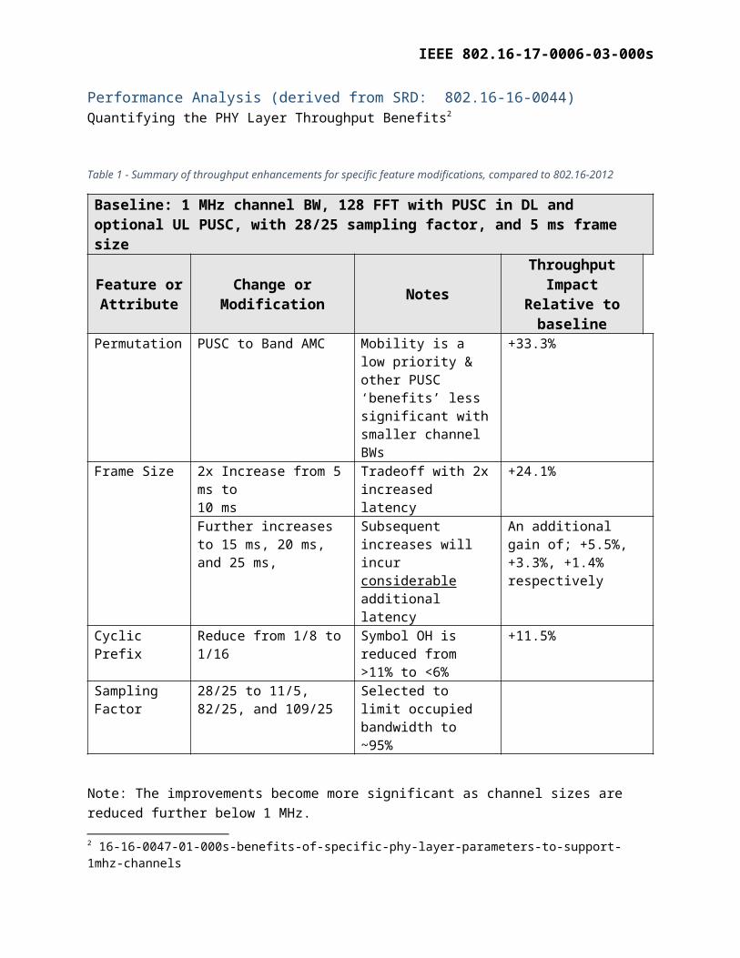
Performance Analysis (derived from SRD: 802.16-16-0044)Quantifying the PHY Layer Throughput Benefits2
Table 1 - Summary of throughput enhancements for specific feature modifications, compared to 802.16-2012
Baseline: 1 MHz channel BW, 128 FFT with PUSC in DL and optional UL PUSC, with 28/25 sampling factor, and 5 ms frame size
Feature or Attribute Change or Modification Notes Throughput Impact
Relative to baselinePermutation PUSC to Band AMC Mobility is a low priority
& other PUSC ‘benefits’ less significant with smaller channel BWs
+33.3%
Frame Size 2x Increase from 5 ms to 10 ms
Tradeoff with 2x increased latency
+24.1%
Further increases to 15 ms, 20 ms, and 25 ms,
Subsequent increases will incur considerable additional latency
An additional gain of; +5.5%, +3.3%, +1.4% respectively
Cyclic Prefix Reduce from 1/8 to 1/16 Symbol OH is reduced from >11% to <6%
+11.5%
Sampling Factor 28/25 to 11/5, 82/25, and 109/25
Selected to limit occupied bandwidth to ~95%
Note: The improvements become more significant as channel sizes are reduced further below 1 MHz.
2 16-16-0047-01-000s-benefits-of-specific-phy-layer-parameters-to-support-1mhz-channels
IEEE 802.16-17-0006-03-000s
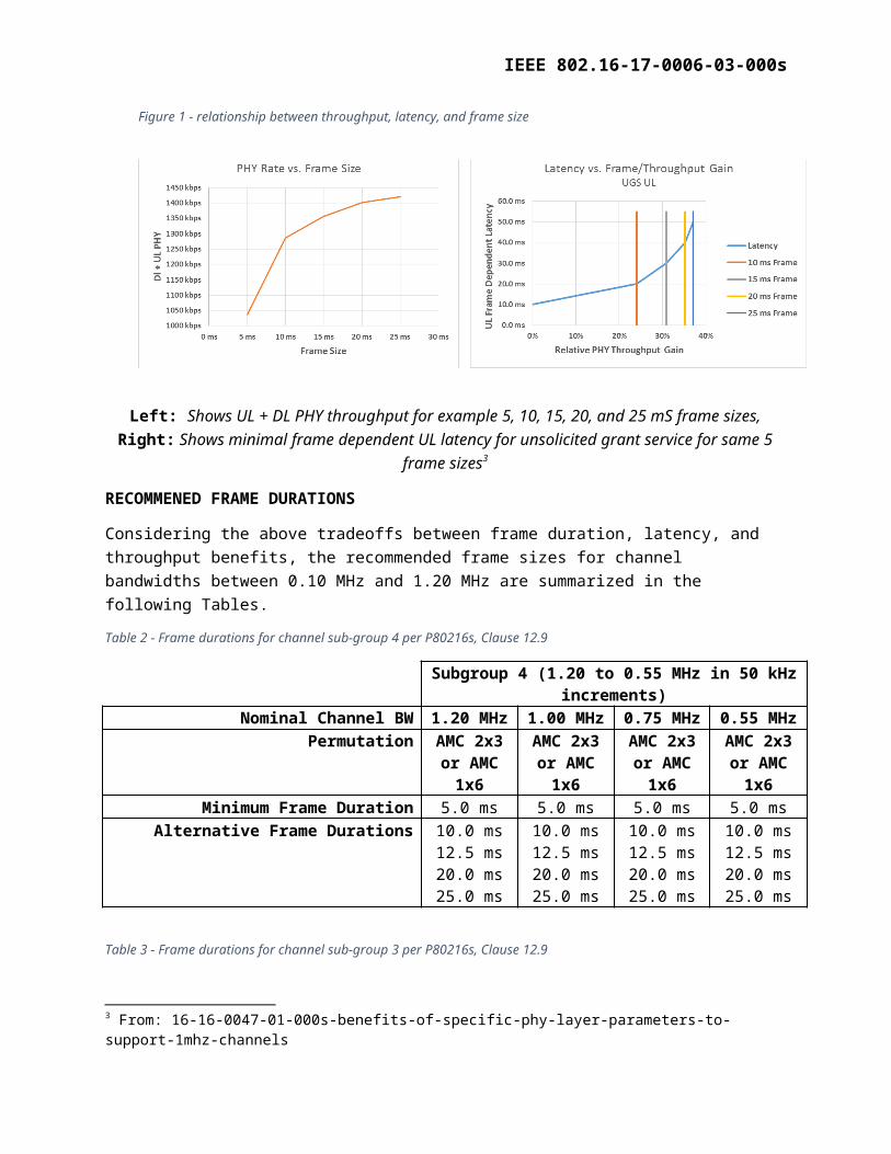
Left: Shows UL + DL PHY throughput for example 5, 10, 15, 20, and 25 mS frame sizes, Right: Shows minimal frame dependent UL latency for unsolicited grant service for same 5 frame sizes3
RECOMMENED FRAME DURATIONS
Considering the above tradeoffs between frame duration, latency, and throughput benefits, the recommended frame sizes for channel bandwidths between 0.10 MHz and 1.20 MHz are summarized in the following Tables.
Table 2 - Frame durations for channel sub-group 4 per P80216s, Clause 12.9
Subgroup 4 (1.20 to 0.55 MHz in 50 kHz increments)Nominal Channel BW 1.20 MHz 1.00 MHz 0.75 MHz 0.55 MHz
Permutation AMC 2x3 or AMC 1x6
AMC 2x3 or AMC 1x6
AMC 2x3 or AMC 1x6
AMC 2x3 or AMC 1x6
Minimum Frame Duration 5.0 ms 5.0 ms 5.0 ms 5.0 msAlternative Frame Durations 10.0 ms 10.0 ms 10.0 ms 10.0 ms
12.5 ms 12.5 ms 12.5 ms 12.5 ms20.0 ms 20.0 ms 20.0 ms 20.0 ms25.0 ms 25.0 ms 25.0 ms 25.0 ms
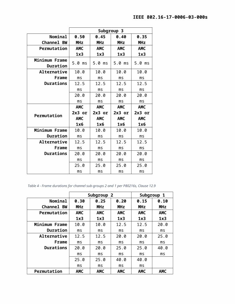
Table 3 - Frame durations for channel sub-group 3 per P80216s, Clause 12.9
Subgroup 3Nominal Channel BW 0.50 MHz 0.45 MHz 0.40 MHz 0.35 MHz
Permutation AMC 1x3 AMC 1x3 AMC 1x3 AMC 1x3Minimum Frame
Duration 5.0 ms 5.0 ms 5.0 ms 5.0 ms
Alternative Frame Durations
10.0 ms 10.0 ms 10.0 ms 10.0 ms12.5 ms 12.5 ms 12.5 ms 12.5 ms20.0 ms 20.0 ms 20.0 ms 20.0 ms
PermutationAMC 2x3 or AMC
1x6
AMC 2x3 or AMC
1x6
AMC 2x3 or AMC
1x6
AMC 2x3 or AMC
1x6Minimum Frame 10.0 ms 10.0 ms 10.0 ms 10.0 ms
3 From: 16-16-0047-01-000s-benefits-of-specific-phy-layer-parameters-to-support-1mhz-channels
Figure 1 - relationship between throughput, latency, and frame size
IEEE 802.16-17-0006-03-000s
Subgroup 3Duration
Alternative Frame Durations
12.5 ms 12.5 ms 12.5 ms 12.5 ms20.0 ms 20.0 ms 20.0 ms 20.0 ms25.0 ms 25.0 ms 25.0 ms 25.0 ms
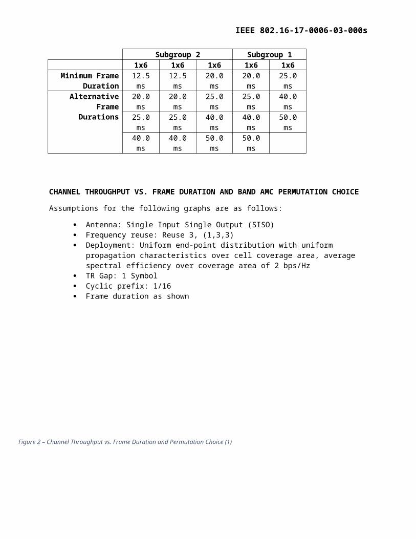
Table 4 - Frame durations for channel sub-groups 2 and 1 per P80216s, Clause 12.9
Subgroup 2 Subgroup 1Nominal Channel BW 0.30 MHz 0.25 MHz 0.20 MHz 0.15 MHz 0.10 MHz
Permutation AMC 1x3 AMC 1x3 AMC 1x3 AMC 1x3 AMC 1x3Minimum Frame
Duration 10.0 ms 10.0 ms 12.5 ms 12.5 ms 20.0 ms
Alternative Frame Durations
12.5 ms 12.5 ms 20.0 ms 20.0 ms 25.0 ms20.0 ms 20.0 ms 25.0 ms 25.0 ms 40.0 ms25.0 ms 25.0 ms 40.0 ms 40.0 ms
Permutation AMC 1x6 AMC 1x6 AMC 1x6 AMC 1x6 AMC 1x6Minimum Frame
Duration 12.5 ms 12.5 ms 20.0 ms 20.0 ms 25.0 ms
Alternative Frame Durations
20.0 ms 20.0 ms 25.0 ms 25.0 ms 40.0 ms25.0 ms 25.0 ms 40.0 ms 40.0 ms 50.0 ms40.0 ms 40.0 ms 50.0 ms 50.0 ms
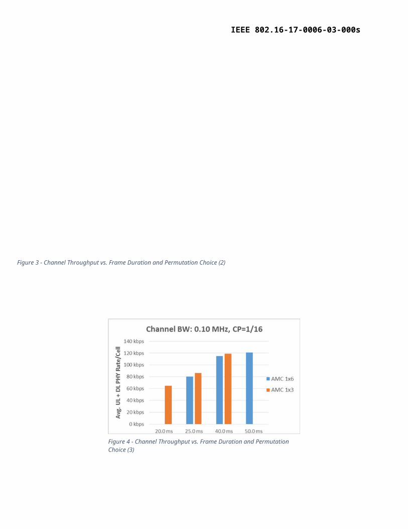
CHANNEL THROUGHPUT VS. FRAME DURATION AND BAND AMC PERMUTATION CHOICE
Assumptions for the following graphs are as follows:
Antenna: Single Input Single Output (SISO) Frequency reuse: Reuse 3, (1,3,3) Deployment: Uniform end-point distribution with uniform propagation characteristics over
cell coverage area, average spectral efficiency over coverage area of 2 bps/Hz TR Gap: 1 Symbol Cyclic prefix: 1/16 Frame duration as shown
Figure 2 – Channel Throughput vs. Frame Duration and Permutation Choice (1)
IEEE 802.16-17-0006-03-000s
Figure 3 - Channel Throughput vs. Frame Duration and Permutation Choice (2)
Figure 4 - Channel Throughput vs. Frame Duration and Permutation Choice (3)
IEEE 802.16-17-0006-03-000s
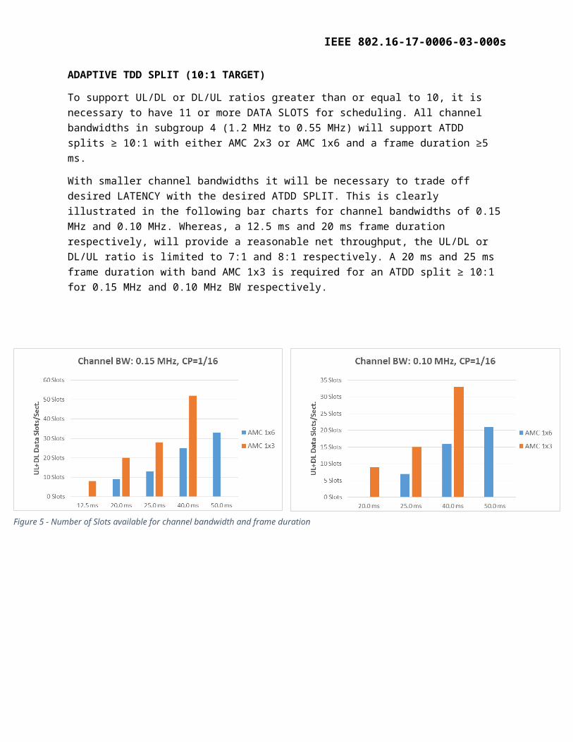
ADAPTIVE TDD SPLIT (10:1 TARGET)
To support UL/DL or DL/UL ratios greater than or equal to 10, it is necessary to have 11 or more DATA SLOTS for scheduling. All channel bandwidths in subgroup 4 (1.2 MHz to 0.55 MHz) will support ATDD splits ≥ 10:1 with either AMC 2x3 or AMC 1x6 and a frame duration ≥5 ms.
With smaller channel bandwidths it will be necessary to trade off desired LATENCY with the desired ATDD SPLIT. This is clearly illustrated in the following bar charts for channel bandwidths of 0.15 MHz and 0.10 MHz. Whereas, a 12.5 ms and 20 ms frame duration respectively, will provide a reasonable net throughput, the UL/DL or DL/UL ratio is limited to 7:1 and 8:1 respectively. A 20 ms and 25 ms frame duration with band AMC 1x3 is required for an ATDD split ≥ 10:1 for 0.15 MHz and 0.10 MHz BW respectively.
Figure 5 - Number of Slots available for channel bandwidth and frame duration
IEEE 802.16-17-0006-03-000s
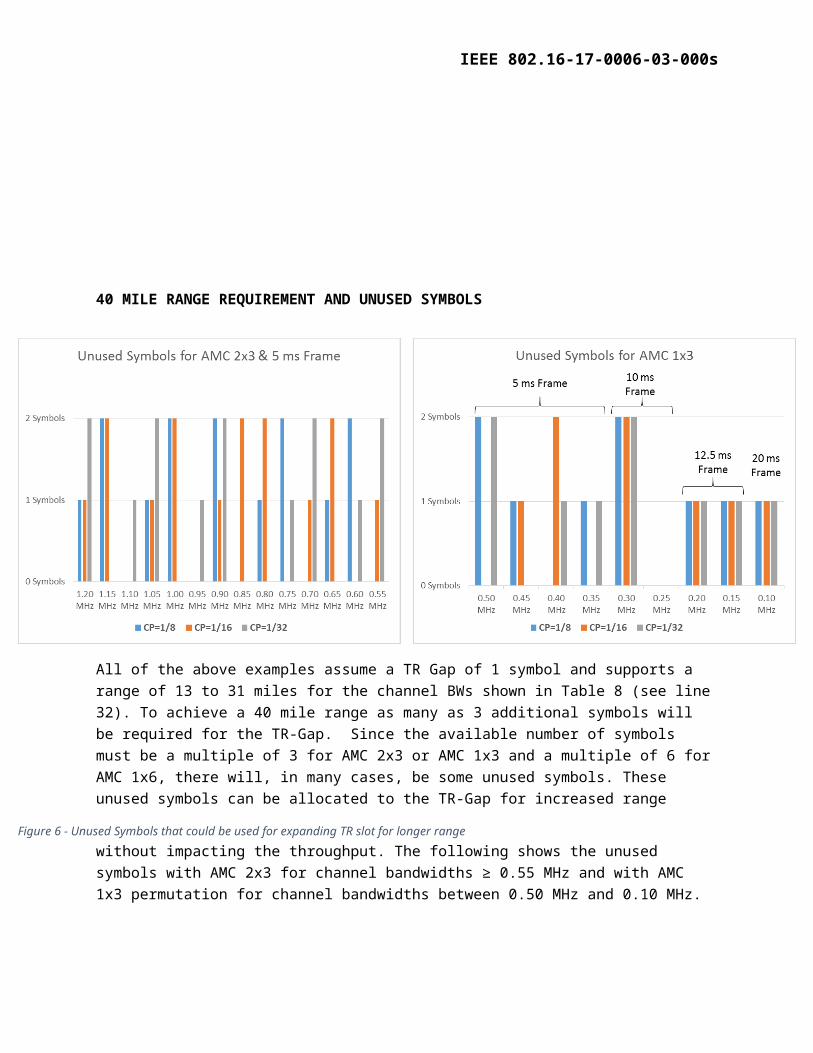
40 MILE RANGE REQUIREMENT AND UNUSED SYMBOLS
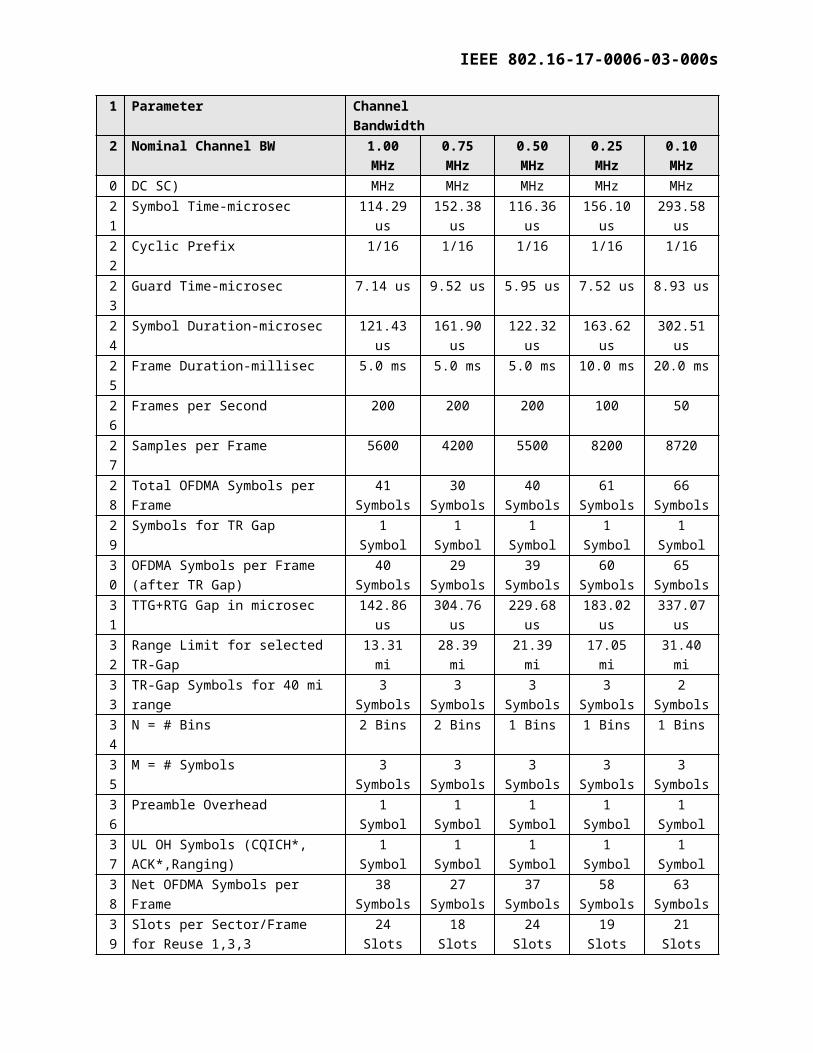
All of the above examples assume a TR Gap of 1 symbol and supports a range of 13 to 31 miles for the channel BWs shown in Table 8 (see line 32). To achieve a 40 mile range as many as 3 additional symbols will be required for the TR-Gap. Since the available number of symbols must be a multiple of 3 for AMC 2x3 or AMC 1x3 and a multiple of 6 for AMC 1x6, there will, in many cases, be some unused symbols. These unused symbols can be allocated to the TR-Gap for increased range without impacting the throughput. The following shows the unused symbols with AMC 2x3 for channel bandwidths ≥ 0.55 MHz
and with AMC 1x3 permutation for channel bandwidths between 0.50 MHz and 0.10 MHz.
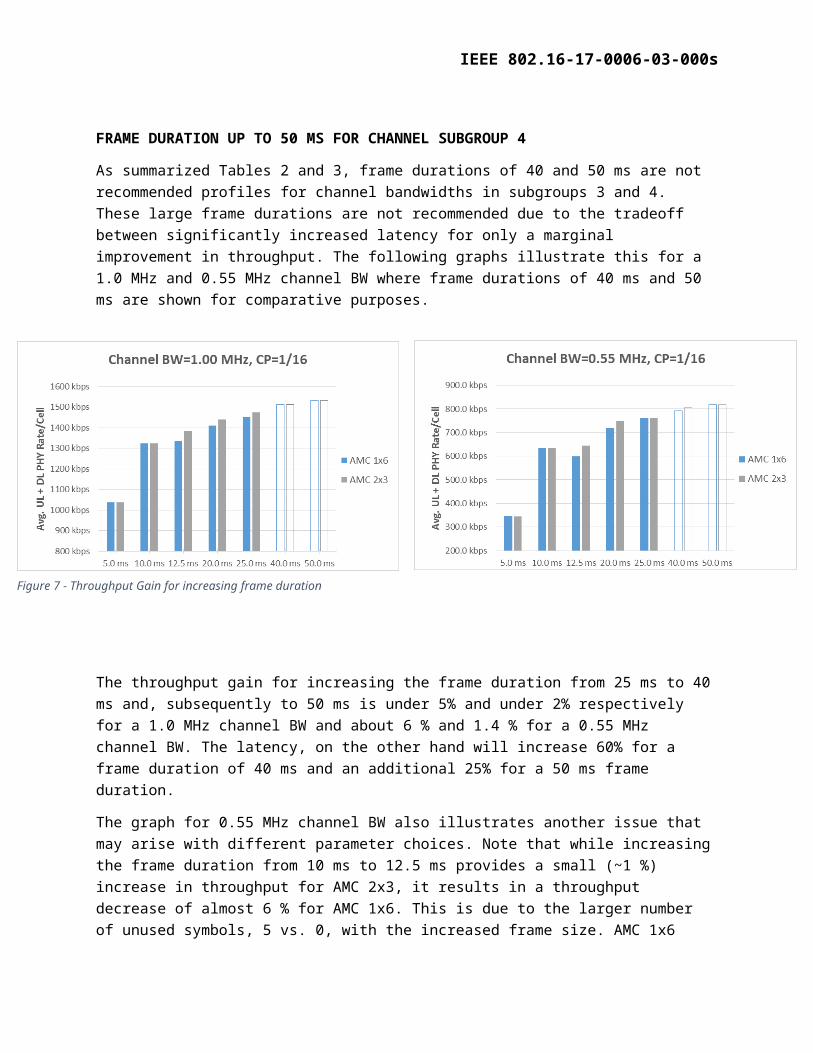
FRAME DURATION UP TO 50 MS FOR CHANNEL SUBGROUP 4
As summarized Tables 2 and 3, frame durations of 40 and 50 ms are not recommended profiles for channel bandwidths in subgroups 3 and 4. These large frame durations are not recommended due to the tradeoff between significantly increased latency for only a marginal improvement in throughput. The following graphs illustrate this for a 1.0 MHz and 0.55 MHz channel BW where frame durations of 40 ms and 50 ms are shown for comparative purposes.
Figure 6 - Unused Symbols that could be used for expanding TR slot for longer range
IEEE 802.16-17-0006-03-000s
The throughput gain for increasing the frame duration from 25 ms to 40 ms and, subsequently to 50 ms is under 5% and under 2% respectively for a 1.0 MHz channel BW and about 6 % and 1.4 % for a 0.55 MHz channel BW. The latency, on the other hand will increase 60% for a frame duration of 40 ms and an additional 25% for a 50 ms frame duration.
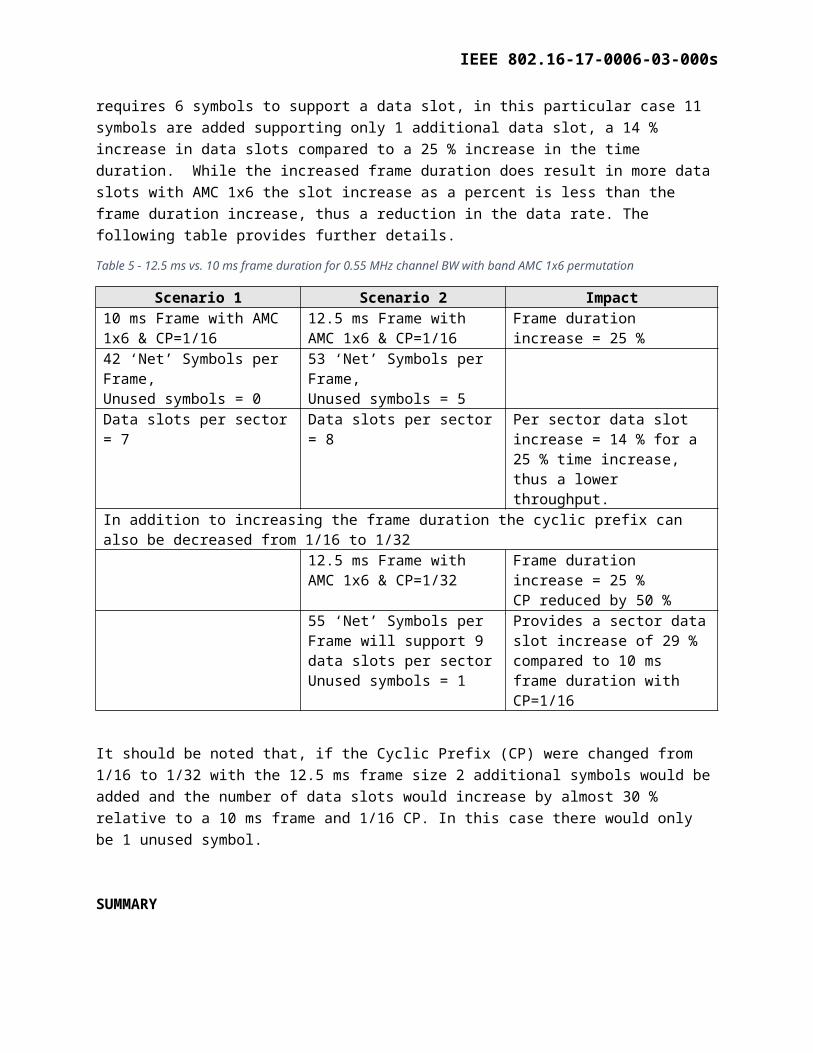
The graph for 0.55 MHz channel BW also illustrates another issue that may arise with different parameter choices. Note that while increasing the frame duration from 10 ms to 12.5 ms provides a small (~1 %) increase in throughput for AMC 2x3, it results in a throughput decrease of almost 6 % for AMC 1x6. This is due to the larger number of unused symbols, 5 vs. 0, with the increased frame size. AMC 1x6 requires 6 symbols to support a data slot, in this particular case 11 symbols are added supporting only 1 additional data slot, a 14 % increase in data slots compared to a 25 % increase in the time duration. While the increased frame duration does result in more data slots with AMC 1x6 the slot increase as a percent is less than the frame duration increase, thus a reduction in the data rate. The following table provides further details.
Table 5 - 12.5 ms vs. 10 ms frame duration for 0.55 MHz channel BW with band AMC 1x6 permutation
Scenario 1 Scenario 2 Impact10 ms Frame with AMC 1x6 & CP=1/16
12.5 ms Frame with AMC 1x6 & CP=1/16
Frame duration increase = 25 %
42 ‘Net’ Symbols per Frame, Unused symbols = 0
53 ‘Net’ Symbols per Frame,Unused symbols = 5
Data slots per sector = 7 Data slots per sector = 8 Per sector data slot increase = 14 % for a 25 % time increase, thus a lower throughput.
In addition to increasing the frame duration the cyclic prefix can also be decreased from 1/16 to 1/3212.5 ms Frame with AMC 1x6 & CP=1/32
Frame duration increase = 25 %CP reduced by 50 %
55 ‘Net’ Symbols per Frame will support 9 data slots per sectorUnused symbols = 1
Provides a sector data slot increase of 29 % compared to 10 ms frame duration with CP=1/16
It should be noted that, if the Cyclic Prefix (CP) were changed from 1/16 to 1/32 with the 12.5 ms frame size 2 additional symbols would be added and the number of data slots would increase by almost 30 % relative to a 10 ms frame and 1/16 CP. In this case there would only be 1 unused symbol.
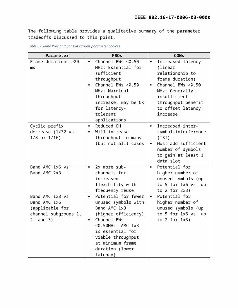
SUMMARY
The following table provides a qualitative summary of the parameter tradeoffs discussed to this point.
Table 6 - Some Pros and Cons of various parameter choices
Parameter PROs CONsFrame durations >20 ms Channel BWs ≤0.50 MHz: Increased latency (linear
IEEE 802.16-17-0006-03-000s
Parameter PROs CONsEssential for sufficient throughput
Channel BWs >0.50 MHz: Marginal throughput increase, may be OK for latency-tolerant applications
relationship to frame duration)
Channel BWs >0.50 MHz: Generally insufficient throughput benefit to offset latency increase
Cyclic prefix decrease (1/32 vs. 1/8 or 1/16)
Reduced OH Will increase throughput in
many (but not all) cases
Increased inter-symbol-interference (ISI)
Must add sufficient number of symbols to gain at least 1 data slot
Band AMC 1x6 vs. Band AMC 2x3
2x more sub-channels for increased flexibility with frequency reuse
Potential for higher number of unused symbols (up to 5 for 1x6 vs. up to 2 for 2x3)
Band AMC 1x3 vs. Band AMC 1x6 (applicable for channel subgroups 1, 2, and 3)
Potential for fewer unused symbols with Band AMC 1x3 (higher efficiency)
Channel BWs ≤0.50MHz: AMC 1x3 is essential for viable throughput at minimum frame duration (lower latency)
Potential for higher number of unused symbols (up to 5 for 1x6 vs. up to 2 for 1x3)
IEEE 802.16-17-0006-03-000s
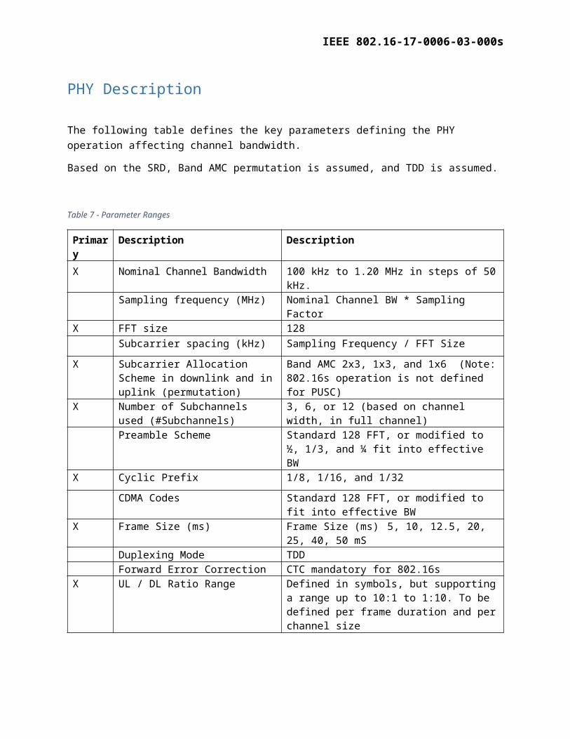
PHY Description
The following table defines the key parameters defining the PHY operation affecting channel bandwidth.
Based on the SRD, Band AMC permutation is assumed, and TDD is assumed.
Table 7 - Parameter Ranges
Primary Description Description
X Nominal Channel Bandwidth 100 kHz to 1.20 MHz in steps of 50 kHz. Sampling frequency (MHz) Nominal Channel BW * Sampling Factor
X FFT size 128Subcarrier spacing (kHz) Sampling Frequency / FFT Size
X Subcarrier Allocation Scheme in downlink and in uplink (permutation)
Band AMC 2x3, 1x3, and 1x6 (Note: 802.16s operation is not defined for PUSC)
X Number of Subchannels used (#Subchannels)
3, 6, or 12 (based on channel width, in full channel)
Preamble Scheme Standard 128 FFT, or modified to ½, 1/3, and ¼ fit into effective BW
X Cyclic Prefix 1/8, 1/16, and 1/32
CDMA Codes Standard 128 FFT, or modified to fit into effective BW
X Frame Size (ms) Frame Size (ms) 5, 10, 12.5, 20, 25, 40, 50 mS
Duplexing Mode TDDForward Error Correction CTC mandatory for 802.16s
X UL / DL Ratio Range Defined in symbols, but supporting a range up to 10:1 to 1:10. To be defined per frame duration and per channel size
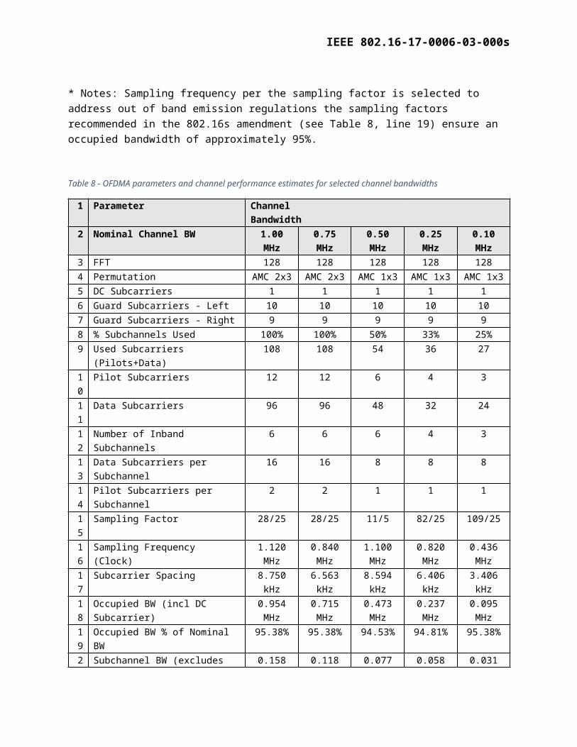
* Notes: Sampling frequency per the sampling factor is selected to address out of band emission regulations the sampling factors recommended in the 802.16s amendment (see Table 8, line 19) ensure an occupied bandwidth of approximately 95%.
Table 8 - OFDMA parameters and channel performance estimates for selected channel bandwidths
1 Parameter Channel Bandwidth2 Nominal Channel BW 1.00 MHz 0.75 MHz 0.50 MHz 0.25 MHz 0.10 MHz3 FFT 128 128 128 128 1284 Permutation AMC 2x3 AMC 2x3 AMC 1x3 AMC 1x3 AMC 1x3
IEEE 802.16-17-0006-03-000s
1 Parameter Channel Bandwidth2 Nominal Channel BW 1.00 MHz 0.75 MHz 0.50 MHz 0.25 MHz 0.10 MHz5 DC Subcarriers 1 1 1 1 16 Guard Subcarriers - Left 10 10 10 10 107 Guard Subcarriers - Right 9 9 9 9 98 % Subchannels Used 100% 100% 50% 33% 25%9 Used Subcarriers (Pilots+Data) 108 108 54 36 27
10 Pilot Subcarriers 12 12 6 4 311 Data Subcarriers 96 96 48 32 2412 Number of Inband Subchannels 6 6 6 4 313 Data Subcarriers per Subchannel 16 16 8 8 814 Pilot Subcarriers per Subchannel 2 2 1 1 115 Sampling Factor 28/25 28/25 11/5 82/25 109/2516 Sampling Frequency (Clock) 1.120 MHz 0.840 MHz 1.100 MHz 0.820 MHz 0.436 MHz17 Subcarrier Spacing 8.750 kHz 6.563 kHz 8.594 kHz 6.406 kHz 3.406 kHz18 Occupied BW (incl DC Subcarrier) 0.954 MHz 0.715 MHz 0.473 MHz 0.237 MHz 0.095 MHz19 Occupied BW % of Nominal BW 95.38% 95.38% 94.53% 94.81% 95.38%20 Subchannel BW (excludes DC SC) 0.158 MHz 0.118 MHz 0.077 MHz 0.058 MHz 0.031 MHz21 Symbol Time-microsec 114.29 us 152.38 us 116.36 us 156.10 us 293.58 us22 Cyclic Prefix 1/16 1/16 1/16 1/16 1/1623 Guard Time-microsec 7.14 us 9.52 us 5.95 us 7.52 us 8.93 us24 Symbol Duration-microsec 121.43 us 161.90 us 122.32 us 163.62 us 302.51 us25 Frame Duration-millisec 5.0 ms 5.0 ms 5.0 ms 10.0 ms 20.0 ms26 Frames per Second 200 200 200 100 5027 Samples per Frame 5600 4200 5500 8200 872028 Total OFDMA Symbols per Frame 41
Symbols30
Symbols40
Symbols61
Symbols66
Symbols29 Symbols for TR Gap 1 Symbol 1 Symbol 1 Symbol 1 Symbol 1 Symbol30 OFDMA Symbols per Frame (after TR
Gap)40
Symbols29
Symbols39
Symbols60
Symbols65
Symbols31 TTG+RTG Gap in microsec 142.86 us 304.76 us 229.68 us 183.02 us 337.07 us32 Range Limit for selected TR-Gap 13.31 mi 28.39 mi 21.39 mi 17.05 mi 31.40 mi33 TR-Gap Symbols for 40 mi range 3 Symbols 3 Symbols 3 Symbols 3 Symbols 2 Symbols34 N = # Bins 2 Bins 2 Bins 1 Bins 1 Bins 1 Bins35 M = # Symbols 3 Symbols 3 Symbols 3 Symbols 3 Symbols 3 Symbols36 Preamble Overhead 1 Symbol 1 Symbol 1 Symbol 1 Symbol 1 Symbol37 UL OH Symbols (CQICH*,
ACK*,Ranging)1 Symbol 1 Symbol 1 Symbol 1 Symbol 1 Symbol
38 Net OFDMA Symbols per Frame 38 Symbols
27 Symbols
37 Symbols
58 Symbols
63 Symbols
39 Slots per Sector/Frame for Reuse 1,3,3
24 Slots 18 Slots 24 Slots 19 Slots 21 Slots
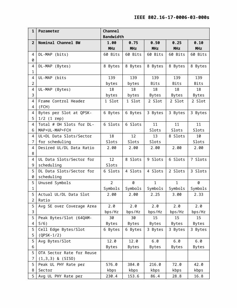
40 DL-MAP (bits) 60 Bits 60 Bits 60 Bits 60 Bits 60 Bits41 DL-MAP (Bytes) 8 Bytes 8 Bytes 8 Bytes 8 Bytes 8 Bytes42 UL-MAP (bits 139 bytes 139 bytes 139 Bits 139 Bits 139 Bits
IEEE 802.16-17-0006-03-000s
1 Parameter Channel Bandwidth2 Nominal Channel BW 1.00 MHz 0.75 MHz 0.50 MHz 0.25 MHz 0.10 MHz
43 UL-MAP (Bytes) 18 bytes 18 bytes 18 Bytes 18 Bytes 18 Bytes44 Frame Control Header (FCH) 1 Slot 1 Slot 2 Slot 2 Slot 2 Slot45 Bytes per Slot at QPSK-1/2 (1 rep) 6 Bytes 6 Bytes 3 Bytes 3 Bytes 3 Bytes46 Total # OH Slots for DL-MAP+UL-
MAP+FCH6 Slots 6 Slots 11 Slots 11 Slots 11 Slots
47 UL+DL Data Slots/Sector for scheduling
18 Slots 12 Slots 13 Slots 8 Slots 10 Slots
48 Desired UL/DL Data Ratio 2.00 2.00 2.00 2.00 2.0049 UL Data Slots/Sector for scheduling 12 Slots 8 Slots 9 Slots 6 Slots 7 Slots50 DL Data Slots/Sector for scheduling 6 Slots 4 Slots 4 Slots 2 Slots 3 Slots51 Unused Symbols 2 Symbols 0 Symbols 1 Symbols 1 Symbols 0 Symbols52 Actual UL/DL Data Slot Ratio 2.00 2.00 2.25 3.00 2.3353 Avg SE over Coverage Area 2.0 bps/Hz 2.0 bps/Hz 2.0 bps/Hz 2.0 bps/Hz 2.0 bps/Hz54 Peak Bytes/Slot (64QAM-5/6) 30 Bytes 30 Bytes 15 Bytes 15 Bytes 15 Bytes55 Cell Edge Bytes/Slot (QPSK-1/2) 6 Bytes 6 Bytes 3 Bytes 3 Bytes 3 Bytes56 Avg Bytes/Slot 12.0 Bytes 12.0 Bytes 6.0 Bytes 6.0 Bytes 6.0 Bytes57 OTA Sector Rate for Reuse (1,3,3) &
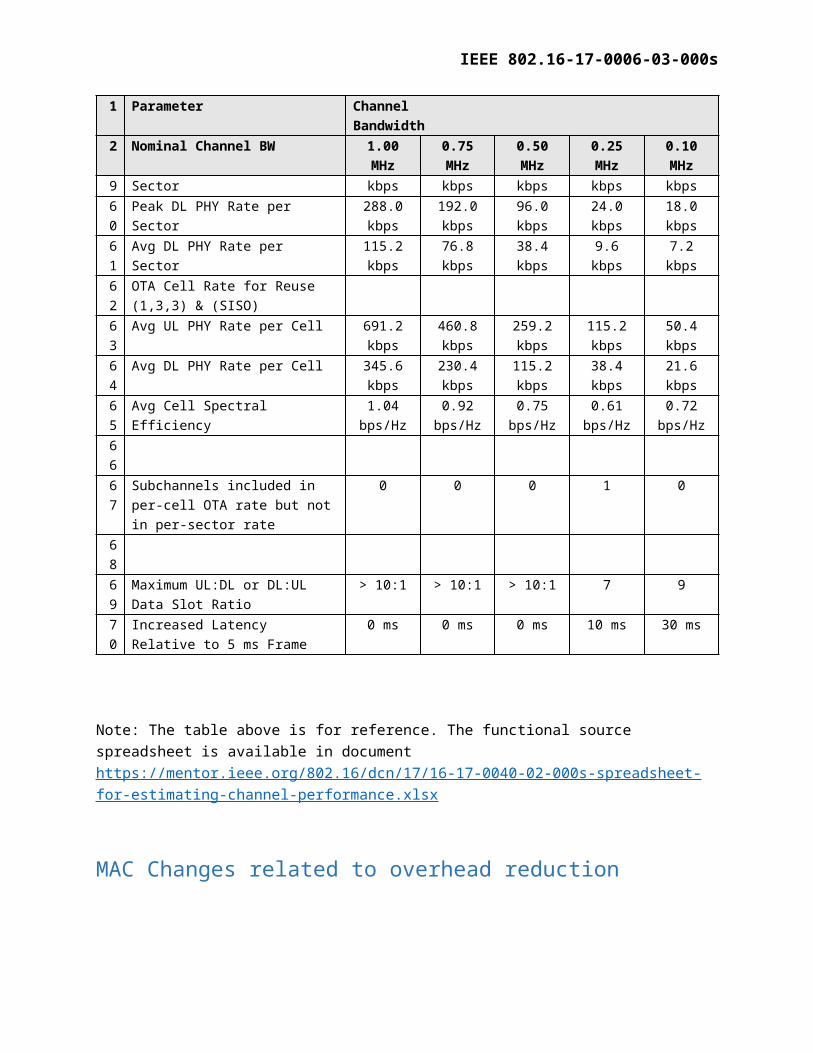
(SISO)58 Peak UL PHY Rate per Sector 576.0 kbps 384.0 kbps 216.0 kbps 72.0 kbps 42.0 kbps59 Avg UL PHY Rate per Sector 230.4 kbps 153.6 kbps 86.4 kbps 28.8 kbps 16.8 kbps60 Peak DL PHY Rate per Sector 288.0 kbps 192.0 kbps 96.0 kbps 24.0 kbps 18.0 kbps61 Avg DL PHY Rate per Sector 115.2 kbps 76.8 kbps 38.4 kbps 9.6 kbps 7.2 kbps62 OTA Cell Rate for Reuse (1,3,3) &
(SISO)63 Avg UL PHY Rate per Cell 691.2 kbps 460.8 kbps 259.2 kbps 115.2 kbps 50.4 kbps64 Avg DL PHY Rate per Cell 345.6 kbps 230.4 kbps 115.2 kbps 38.4 kbps 21.6 kbps65 Avg Cell Spectral Efficiency 1.04
bps/Hz0.92
bps/Hz0.75
bps/Hz0.61
bps/Hz0.72
bps/Hz6667 Subchannels included in per-cell OTA
rate but not in per-sector rate0 0 0 1 0
6869 Maximum UL:DL or DL:UL Data Slot
Ratio> 10:1 > 10:1 > 10:1 7 9
70 Increased Latency Relative to 5 ms Frame
0 ms 0 ms 0 ms 10 ms 30 ms
Note: The table above is for reference. The functional source spreadsheet is available in document https://mentor.ieee.org/802.16/dcn/17/16-17-0040-02-000s-spreadsheet-for-estimating-channel-performance.xlsx
IEEE 802.16-17-0006-03-000s
MAC Changes related to overhead reduction
MAC Layer Modifications for efficiency (From 16-16-0059r0)1. The standard GMAC4 header is shown below. The number in bracket indicates the respective
field size in bits. This structure is used in the standard for both the DL and UL MAPs.
HT (1) EC(1) Type (6) ESF(1)
CI(1) EKS(2) Rsv(1) LEN MSB(3)
LEN LSB (8) CID MSB (8)
CID LSB (8) HCS (8)
Table 9 - GMAC Header
2. Modified DLMAP GMAC header structure for channel BWs less than 1.25 MHz: the DLMAP is always the first burst in the DLSF so it can be identified as DLMAP directly. CID indication is therefore not needed at the receiver side. The modified GMAC header consists of 1 byte length field and 1 byte for HCS field.
LEN (8) HCS (8)
Table 10 - Modified DLMAP GMAC header:
1. Modified ULMAP GMAC header structure for channel BWs less than 1.25 MHz:
a. The ULMAP, if present, is the first data burst in the DLSF after DL-MAP, but it may not always be present in a frame in which case, the first burst may carry data traffic. To avoid conflict, we propose to use the first bit HT = 1 as the key to identify the burst as ULMAP.
b. The modified UL MAP has reserved 7 bits for ULMAP length indication as it cannot exceed 128 bytes.
HT (1) LEN (7) HCS(8)
Table 11 - Modified ULMAP GMAC header:
2. CRC: The standard specifies 32 bit CRC for the PDU. The modified DL/UL MAP has 8 bit CRC. This is justified because the modified MAPs length is drastically reduced. Based on the length field the DLMAP does not exceed 256 bytes and the ULMAP field does not exceed 128
4 In 802.16-2012, GMAC is not used, but spelled out as Generic MAC
IEEE 802.16-17-0006-03-000s
bytes. An 8 bit CRC is sufficient to protect such a short PDU size.
CID switch IE
1. This IE Indicates whether DL-MAP includes CID information or not. We propose to drop this IE and to always drop the CID information in the modified MAP. This can be done since the CID is also included in the data PDU header. This contributes to 12 bits savings.
Modified DL MAP IE structure
1. Rectangular burst geometry is replaced by slots allocation, similar to the ULMAP burst structure. Rectangular fitting of DL bursts is replaced with linear filling of DL bursts. The number of slots per downlink burst is transmitted in the DL MAP IE. Slots allocation per burst is continuous by traversing first in frequency and then in time for a given frame configuration. With linear DLMAP structure, the first slot of the next burst is identified by the last slot of the previous burst. The number of slots per burst is sufficient to define the architecture of the burst.
2. CID information is removed in the modified DLMAP. This implies the remote station PHY layer has to decode all downlink bursts. Filtering of the downlink PDUs of interest to a specific remote is done by the MAC layer based on the CID in the data PDU GMAC header.
3. The information per DL MAP IE includes:a. DIUC – 4 bits (this field is retained from the standard)b. Number of slots per burst – 8 bits (this filed is added).
4. The following fields in the standard DL MAP IE are dropped: N_CID - The number of CIDs in the burst. This is
dropped because the CIDs are not transmitted in the DLMAP. CIDs - This is dropped because the CIDs are not
transmitted in the DLMAP. Symbol Offset - This is dropped due to DL MAP IE geometry change Sub-channel Offset - This is dropped due to DL MAP IE geometry change No of Symbols - This is dropped due to DL MAP IE geometry change No of Sub-channels - This is dropped due to DL MAP IE geometry change Boosting – It is proposed to avoid per burst boosting. Repetition - This is dropped because an unused DIUC value is
employed to identify QPSK1/2 with repetition 2. Due to the high overhead, repetition 4 and 6 should not be used in narrow channels.
IEEE 802.16-17-0006-03-000s
Modified UL MAP IE structure
1. IR/HR & PR/BR IEsInitial Ranging/Handover Ranging (IR/HR) and Periodic Ranging/Bandwidth Request (PR/BR) IEs are used to identify the regions in the ULSF allocated for IR/HR and PR/BR CDMA code transmission.
For 128 FFT, IR/HR and PR/BR extends over a full channel.
The following rules are proposed for the construction of IR and PR IEs: IR/HR and PR/BR allocations extend over a fixed number of OFDMA symbols (e.g., 3
symbols @ 1 MHz wide channel). IR/HR and PR/BR are not allocated at the same frame. IR/HR and PR/BR are always allocated as the first burst in the ULSF. IR/HR is identified by UIUC = 12. PR/BR is identified by UIUC = 10.
With the above rules, the need to identify the geometry of IR/HR and PR/BR bursts is avoided.
Fields retained in the IR/PR IE:
UIUC - 4 bits
The following fields are dropped: OFDMA Symbol Offset - Transmission of geometry information not needed Sub-channel Offset - Transmission of geometry information not needed No of Symbols - Transmission of geometry information not needed No of Sub-channels - Transmission of geometry information not needed Ranging Method – 0b00 Indicates 2 symbol initial/handover ranging 0b10 Indicates 1
symbol periodic/BR ranging. This is indicated by separate UIUC so dropped Ranging Indicator - 0b0 Indicates normal ranging 0b1 Indicates dedicated ranging. This
is dropped as we propose to always do normal ranging CID – IR and PR bursts are always transmitted using broadcast CID.
2. DATA Burst IE (UIUC = 1 to 8)
UL data burst geometry is defined by the “duration” field which contains the number of slots in the burst. Slots allocation per burst is continuous by traversing first in time and then in frequency for a given frame configuration. We propose to drop the repetition field and a new UIUC value for QPSK ½ with repetition 2.
The modified data burst IE includes:
CID – 16 bits UIUC – 4 bits Duration – 10 bits
3. CDMA-ALLOC IE (UIUC = 14)
IEEE 802.16-17-0006-03-000s
CDMA-ALLOC IE identifies the region in the ULSF in which a remote station should transmit a ranging message.
Modified CDMA- ALLOC IE fields:
UIUC- 4 bits Duration – 4 bits (9 slots allocated, but 4 bits are sufficient). Frame Number Index- 4 bits. Indicates the frame number in which the CDMA code to
which this message responds was transmitted. Ranging Code – 8 bits. Indicates ranging code sent by the remote. BW request mandatory - Indicates whether the remote shall include a BR in the
allocation. Fields dropped:
Ranging Symbol - Well known, can be dropped. Ranging sub channel - Well known, can be dropped.
4. Power Control IE (UIUC = 9)
The standard power control IE which is carried in extended UIUC is replaced with un-used UIUC value 9.
Fields used in the modified power control IE: CID – 8 bits UIUC – 4 bits Power control – 8 bits (change in power level).
Fields dropped: Extended UIUC Length Power Measurement Frame
MAC Management Message (MMM) Structure1. DL MAP MMM Structure Modifications:
Fields used:
Frame number: this field is retained from the standard DL MAP MMM but its length is reduced from 24 bites to 16 bits.
Fields dropped:
Management Message Type = 2
IEEE 802.16-17-0006-03-000s
DLMAP is always the 2nd burst (after FCH) in the DLSF and it is carried in every frame. As such, it can be identified without the presence of the type field which therefore can be dropped.
Frame Duration CodeThis field conveys frame duration with which BS is transmitting. For the given deployment, this is well known information so it need not be transmitted every frame and hence, dropped
DCD Count We propose to maintain DIUC to burst profile/FEC code mapping static per deployment and as such, this parameter can be dropped.
Base Station IDThis information does not need to be carried in DL-MAP every frame. Instead BS can send this information as an additional parameter in registration response. This way this information is exchanges only during network entry which should be sufficient.
Number of OFDMA symbols This filed carrier information about total number of symbols in DL SF
This information changes based on deployment and it is fixed for a given deployment. It can be statically configured at the remote
UL MAP MMM Structure Modifications:
Fields used: None
Fields dropped
Management Message Type = 3ULMAP is always the 3rd burst (after FCH and DLMAP) in the DLSF and it is carried in every frame. As such, it can be identified without the presence of the type field which therefore can be dropped.
FDD Partition flagThis is FDD specific flag hence dropped as system is TDD
Reserved (7 bits) – not used UCD Count
We propose to maintain UIUC to burst profile/FEC code mapping static per deployment and as such, this parameter can be dropped.
Allocation Start TimeUL allocation start time is relative to start of frame. This is well-known at the remote and can be dropped.
Number of OFDMA symbols This field carries information about total number of symbols in ULSF. This information changes based on deployment and it is fixed for a given deployment. So it can be statically configured at the remote.