Embed Size (px)
Citation preview

1
Bandwidth Recycling in IEEE 802.16 NetworksDavid Chuck and J. Morris Chang
Department of Electrical and Computer EngineeringIowa State University, Ames, Iowa 50011, USA
{chuang, morris}@iastate.edu
Abstract—IEEE 802.16 standard was designed to support the bandwidth demanding applications with quality of service (QoS).Bandwidth is reserved for each application to ensure the QoS. For variable bit rate (VBR) applications, however, it is difficult forthe subscriber station (SS) to predict the amount of incoming data. To ensure the QoS guaranteed services, the SS may reservemore bandwidth than its demand. As a result, the reserved bandwidth may not be fully utilized all the time. In this paper, we proposea scheme, named Bandwidth Recycling, to recycle the unused bandwidth without changing the existing bandwidth reservation. Theidea of the proposed scheme is to allow other SSs to utilize the unused bandwidth when it is available. Thus, the system throughputcan be improved while maintaining the same QoS guaranteed services. Mathematical analysis and simulation are used to evaluatethe proposed scheme. Simulation and analysis results confirm that the proposed scheme can recycle 35% of unused bandwidth onaverage. By analyzing factors affecting the recycling performance, three scheduling algorithms are proposed to improve the overallthroughput. The simulation results show that our proposed algorithm improves the overall throughput by 40% in a steady network.
Index Terms—WiMAX, IEEE 802.16, Bandwidth Recycling
F
1 INTRODUCTION
The Worldwide Interoperability for Microwave Access(WiMAX), based on IEEE 802.16 standard standards [1][2], is designed to facilitate services with high trans-mission rates for data and multimedia applications inmetropolitan areas. The physical (PHY) and mediumaccess control (MAC) layers of WiMAX have been spec-ified in the IEEE 802.16 standard. Many advanced com-munication technologies such as Orthogonal Frequency-Division Multiple Access (OFDMA) and multiple-inputand multiple-output (MIMO) are embraced in the stan-dards. Supported by these modern technologies, WiMAXis able to provide a large service coverage, high datarates and QoS guaranteed services. Because of these fea-tures, WiMAX is considered as a promising alternativefor last mile broadband wireless access (BWA).
In order to provide QoS guaranteed services, thesubscriber station (SS) is required to reserve the neces-sary bandwidth from the base station (BS) before anydata transmissions. In order to serve variable bit rate(VBR) applications, the SS tends to keep the reservedbandwidth to maintain the QoS guaranteed services.Thus, the amount of reserved bandwidth transmitteddata may be more than the amount of transmitted dataand may not be fully utilized all the time. Although theamount of reserved bandwidth is adjustable via makingbandwidth requests (BRs), the adjusted bandwidth isapplied as early as to the next coming frame. The unusedbandwidth in the current frame has no chance to beutilized. Moreover, it is very challenging to adjust theamount of reserved bandwidth precisely. The SS may beexposed to the risk of degrading the QoS requirements ofapplications due to the insufficient amount of reserved
bandwidth.To improve the bandwidth utilization while main-
taining the same QoS guaranteed services, our researchobjective is twofold: 1) the existing bandwidth reserva-tion is not changed to maintain the same QoS guaran-teed services. 2) our research work focuses on increas-ing the bandwidth utilization by utilizing the unusedbandwidth. We propose a scheme, named BandwidthRecycling, which recycles the unused bandwidth whilekeeping the same QoS guaranteed services without in-troducing extra delay. The general concept behind ourscheme is to allow other SSs to utilize the unusedbandwidth left by the current transmitting SS. Since theunused bandwidth is not supposed to occur regularly,our scheme allows SSs with non-real time applications,which have more flexibility of delay requirements, to re-cycle the unused bandwidth. Consequently, the unusedbandwidth in the current frame can be utilized. It isdifferent from the bandwidth adjustment in which theadjusted bandwidth is enforced as early as in the nextcoming frame. Moreover, the unused bandwidth is likelyto be released temporarily (i.e., only in the current frame)and the existing bandwidth reservation does not change.Therefore, our scheme improves the overall throughputwhile providing the same QoS guaranteed services.
According to the IEEE 802.16 standard, SSs scheduledon the uplink (UL) map should have transmission op-portunities in the current frame. Those SSs are calledtransmission SSs (TSs) in this paper. The main idea of theproposed scheme is to allow the BS to schedule a backupSS for each TS. The backup SS is assigned to standbyfor any opportunities to recycle the unused bandwidthof its corresponding TS. We call the backup SS as thecomplementary station (CS). In the IEEE 802.16 standard,
IEEE TRANSACTIONS ON MOBILE COMPUTING VOLUME 9 , ISSUE 10 (OCTOBER 2010)

2
BRs are made in per-connection basis. However, theBS allocates bandwidth in per-SS basis. It gives the SSflexibility to allocate the granted bandwidth to eachconnection locally. Therefore, the unused bandwidth isdefined as the granted bandwidth which is still availableafter serving all connections running on the SS. In ourscheme, when a TS has unused bandwidth, it shouldtransmit a message, called releasing message (RM), toinform its corresponding CS to recycle the unused band-width. However, because of the variety of geographicaldistance between TS and CS and the transmission powerof the TS, the CS may not receive the RM. In this case, thebenefit of our scheme may be reduced. In this research,we investigate the probability that the CS receives aRM successfully. Our theoretical analysis shows that thisprobability is least 42%, which is confirmed by our simu-lation. By further investigating the factors that affect theeffectiveness of our scheme, two factors are concluded:1) the CS cannot receive the RM. 2) the CS does nothave non-real time data to transmit while receiving aRM. To mitigate those factors, additional schedulingalgorithms are proposed. Our simulation results showthat the proposed algorithm further improve the averagethroughput by 40% in a steady network (i.e., 15∼75second in our simulation).
The rest of this paper is organized as follows. InSection 2, we provide the background information ofIEEE 802.16. Motivation and related works are presentedin Section 3. The proposed scheme is presented in Section4. The analysis of the proposed scheme and simulationresults are placed in Section 5 and Section 6. In Section7, three additional scheduling algorithms are proposedto enhance the performance of the proposed scheme.The simulation results of each scheduling algorithm areshown in Section 8. At the end, the conclusion is givenin Section 9.
2 BACKGROUND INFORMATIONThe IEEE 802.16 standard specifies three types of trans-mission mediums supported as the physical layer (PHY):single channel (SC), Orthogonal frequency-division mul-tiplexing (OFDM) and Orthogonal Frequency-DivisionMultiple Access (OFDMA). We assume OFDMA as thePHY in our analytical model since it is employed to sup-port mobility in IEEE 802.16e standard and the schemeworking in OFDMA should also work in others. Thereare four types of modulations supported by OFDMA:BPSK, QPSK, 16-QAM and 64-QAM.
This paper is focused on the point-to-multipoint(PMP) mode in which the SS is not allowed to commu-nicate with any other SSs but the BS directly. Based onthe transmission direction, the transmissions between BSand SSs are classified into downlink (DL) and uplink(UL) transmissions. The former are the transmissionsfrom the BS to SSs. Conversely, the latter are the trans-missions in the opposite direction.
There are two transmission modes: Time DivisionDuplex (TDD) and Frequency Division Duplex (FDD)
supported in IEEE 802.16. Both UL and DL transmissionscan not be operated simultaneously in TDD mode butin FDD mode. In this paper, our scheme is focused onthe TDD mode. In WiMAX, the BS is responsible forscheduling both UL and DL transmissions. All schedul-ing behavior is expressed in a MAC frame.
The structure of a MAC frame defined in IEEE 802.16standard contains two parts: UL and DL subframe. TheUL subframe is for UL transmissions. Similarly, the DLsubframe is for DL transmissions. In IEEE 802.16 net-works, the SS is coordinated by the BS. All coordinatinginformation including burst profiles and offsets is inthe DL and UL maps, which are broadcasted at thebeginning of a MAC frame.
The IEEE 802.16 network is connection-oriented. Itgives the advantage of having better control over net-work resource to provide QoS guaranteed services. Inorder to support wide variety of applications, the IEEE802.16 standard classifies traffic into five schedulingclasses: Unsolicited Grant Service (UGS), Real TimePolling Service (rtPS), Non-real Time Polling Service(nrtPS), Best Effort (BE) and Extended Real Time PollingService (ertPS). Each application is classified into one ofthe scheduling classes and establish a connection withthe BS based on its scheduling class. The BS assigns aconnection ID (CID) to each connection. The bandwidthreservation is made based on the CID via sending a BR.When receiving a BR, the BS can either grant or reject theBR depending on its available resources and schedulingpolicies.
There are two types of BRs defined in the IEEE 802.16standard: incremental and aggregate BRs. The formerallow the SS to indicate the extra bandwidth required fora connection. Thus, the amount of reserved bandwidthcan be only increased via incremental BRs. On the otherhand, the SS specifies the current state of queue for theparticular connection via a aggregate request. The BS re-sets its perception of that service’s needs upon receivingthe request. Consequently, the reserved bandwidth maybe decreased.
3 MOTIVATION AND RELATED WORK
Bandwidth reservation allows IEEE 802.16 networks toprovide QoS guaranteed services. The SS reserves therequired bandwidth before any data transmissions. Dueto the nature of VBR applications, it is very difficult forthe SS to make the optimal bandwidth reservation. It ispossible that the amount of reserved bandwidth is morethan the demand. Therefore, the reserved bandwidthcannot be fully utilized. Although the reserved band-width can be adjusted via BRs, however, the updatedreserved bandwidth is applied as early as to the nextcoming frame and there is no way to utilize the unusedbandwidth in the current frame. In our scheme, theSS releases its unused bandwidth in the current frameand another SS pre-assigned by the BS has opportu-nities to utilize this unused bandwidth. This improves
IEEE TRANSACTIONS ON MOBILE COMPUTING VOLUME 9 , ISSUE 10 (OCTOBER 2010)
3
the bandwidth utilization. Moreover, since the existingbandwidth reservation is not changed, the same QoSguaranteed services are provided without introducingany extra delay.
Many research works related to bandwidth utilizationinprovement have been proposed in the literature. In [4],a dynamic resource reservation mechanism is proposed.It can dynamically change the amount of reserved re-source depending on the actual number of active connec-tions. The investigation of dynamic bandwidth reserva-tion for hybrid networks is presented in [3]. The authorsevaluated the performance and effectiveness for the hy-brid network, and proposed efficient methods to ensureoptimum reservation and utilization of bandwidth whileminimizing signal blocking probability and signallingcost. In [5], the authors enhanced the system throughputby using concurrent transmission in mesh mode. Theauthors in [6] proposed a new QoS control scheme byconsidering MAC-PHY cross-layer resource allocation.A dynamic bandwidth request-allocation algorithm forreal-time services is proposed in [7]. The authors predictthe amount of bandwidth to be requested based on theinformation of the backlogged amount of traffic in thequeue and the rate mismatch between packet arrival andservice rate to improve the bandwidth utilization. Theresearch works listed above improve the performanceby predicting the traffic coming in the future. Insteadof prediction, our scheme can allow SSs to accuratelyidentify the portion of unused bandwidth and provides amethod to recycle the unused bandwidth. It can improvethe utilization of bandwidth while keeping the same QoSguaranteed services and introducing no extra delay.
4 PROPOSED SCHEME
The objectives of our research are twofold: 1) The sameQoS guaranteed services are provided by maintainingthe existing bandwidth reservation. 2) the bandwidthutilization is improved by recycling the unused band-width. To achieve these objectives, our scheme namedBandwidth Recycling is proposed. The main idea of theproposed scheme is to allow the BS to pre-assign aCS for each TS at the beginning of a frame. The CSwaits for the possible opportunities to recycle the unusedbandwidth of its corresponding TS in this frame. TheCS information scheduled by the BS is resided in a list,called complementary list (CL). The CL includes themapping relation between each pair of pre-assigned CSand TS. As shown in Fig. 1, each CS is mapped to atleast one TS. The CL is broadcasted followed by the ULmap. To reach the backward compatibility, a broadcastCID (B-CID) is attached in front of the CL. Moreover,a stuff byte value (SBV) is transmitted followed by theB-CID to distinguish the CL from other broadcast DLtransmission intervals.
The UL map including burst profiles and offsets ofeach TS is received by all SSs within the network. Thus,if a SS is on both UL map and CL, the necessary
UL
MA
P
i -1
CL
Transmission
interval of TSk
Possible
transmission
period of CSk
B-C
ID
0xF
F…..TS1 TS2 TS3 TSk …..CS1 CS2 CS3 CSk
TTG
Sep
aration
Fig. 1. The mapping relation between CSs and TSs in aMAC frame
information (e.g., burst profile) residing in the CL maybe reduced to the mapping information between the CSand its corresponding TS. The BS only specifies the burstprofiles for the SSs which are only scheduled on the CL.For example, as shown in Fig. 1, CSj is scheduled asthe corresponding CS of TSj , where 1 ≤ j ≤ k. WhenTSj has unused bandwidth, it performs our protocolintroduced in Section 4.1. If CSj receives the messagesent from TSj , it starts to transmit data by using theagreed burst profile. The burst profile of a CS is residedon either the UL map if the CS is also scheduled onthe UL map or the CL if the CS is only scheduled onCL. Our proposed scheme is presented into two parts:the protocol and the scheduling algorithm. The protocoldescribes how the TS identifies the unused bandwidthand informs recycling opportunities to its correspondingCS. The scheduling algorithm helps the BS to schedulea CS for each TS.
4.1 ProtocolAccording to the IEEE 802.16 standard, the allocatedspace within a data burst that is unused should beinitialized to a known state. Each unused byte shouldbe set as a padding value (i.e., 0xFF), called stuffedbyte value (SBV). If the size of the unused region isat least the size of a MAC header, the entire unusedregion is initialized as a MAC PDU. The padding CIDis used in the CID field of the MAC PDU header. In thisresearch, we intend to recycle the unused space for datatransmissions.
Instead of padding all portion of the unused band-width in our scheme, a TS with unused bandwidthtransmits only a SBV and a RM shown in Fig. 2. The SBVis used to inform the BS that no more data are comingfrom the TS. On the other hand, the RM comprises ageneric MAC PDU with no payload shown in Fig. 3.The mapping information between CL and UL map isbased on the basic CID of each SS. The CID field in RMshould be filled by the basic CID of the TS.
Since there is an agreement of modulation for trans-missions between TS and BS, the SBV can be transmit-
IEEE TRANSACTIONS ON MOBILE COMPUTING VOLUME 9 , ISSUE 10 (OCTOBER 2010)

4
Fig. 2. Messages to release the unused bandwidth withina UL transmission interval.
HT = 0
EC
Rev
CI
Rsv
HT : Header Type
EC : Encryption Control
CID : Connection ID
CI : CRC Indicator
EKS: Encryption Key Sequence
LEN : Length
MSB: Most Significant Bit
LSB : Least Significant Bt
HCS: Header Check Sequence
Fig. 3. The format of RM
ted via this agreed modulation. However, there are noagreed modulations between TS and CS. Moreover, thetransmission coverage of the RM should be as largeas possible in order to maximize the probability thatthe RM is able to be received successfully by the CS.To maximize the transmission coverage of the RM, onepossible solution is to increase the transmission power ofthe TS while transmitting the RM. However, the powermay be a critical resource for the TS and should not be in-creased dramatically. Therefore, under the circumstanceof without increasing the transmission power of the TS,the RM should be transmitted via BPSK which has thelargest coverage among all modulations supported in theIEEE 802.16 standard.
For example, Fig. 4 illustrates the physical location ofthe BS, TS and CS, respectively. The solid circle repre-sents the coverage of QPSK which is the modulationfor data transmissions between BS and TS. When theTS has unused bandwidth, it transmits a SBV via thismodulation (i.e., QPSK) to inform the BS that there areno more data coming from the TS. It is easy to observethat the corresponding CS is out of QPSK coverage.In order to maximize the coverage of the RM underthe circumstance of without increasing the transmissionpower of the TS, the TS transmits the RM via BPSKwhich coverage is represented by the dished circle. Theradius of the dished circle is KL, where L is the distancebetween TS and BS and K is the ratio of transmissionrange of BPSK to the transmission range of QPSK de-pending on the transmission power. Assume all channelsare in good condition. As long as the CS is within thecoverage of BPSK, it can receive the RM successfully andstart to recycle the unused bandwidth.
Since both UL map and CL can be received by the CS,the CS knows the UL transmission period of its corre-sponding TS. This period is called the UL transmissioninterval. The CS monitors this interval to see if a RM
Fig. 4. An example of corresponding locations of TS, BSand CS.
is received from its corresponding TS. Once received,the CS starts to recycle the unused bandwidth by usingthe burst profile residing in either UL map (if the CSis scheduled on the UL map) or CL (if the CS is onlyscheduled on the CL), until using up the rest of the TS’stransmission interval. If the CS does not have any datato transmit, it simply pads the rest of the transmissioninterval.
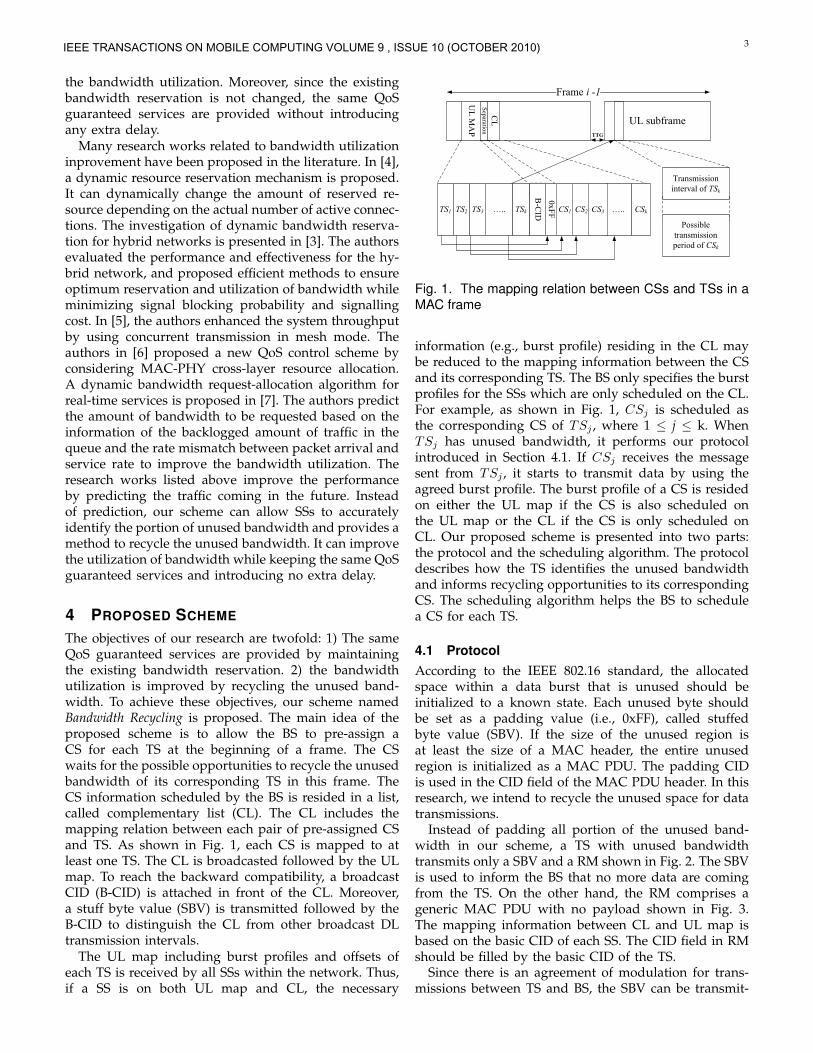
4.2 Scheduling AlgorithmAssume Q represents the set of SSs serving non-real timeconnections (i.e., nrtPS or BE connections) and T is theset of TSs. Due to the feature of TDD that the UL andDL operations can not be performed simultaneously, wecan not schedule the SS which UL transmission intervalis overlapped with the target TS. For any TS, St, let Ot bethe set of SSs which UL transmission interval overlapswith that of St in Q. Thus, the possible corresponding CSof St must be in Q−Ot. All SSs in Q−Ot are consideredas candidates of the CS for St. A scheduling algorithm,called Priority-based Scheduling Algorithm (PSA), shownin Algorithm 1 is used to schedule a SS with the highestpriority as the CS. The priority of each candidate isdecided based on the scheduling factor (SF) definedas the ratio of the current requested bandwidth (CR)to the current granted bandwidth (CG). The SS withhigher SF has more demand on the bandwidth. Thus,we give the higher priority to those SSs. The highestpriority is given to the SSs with zero CG. Non-realtime connections include nrtPS and BE connections. ThenrtPS connections should have higher priority than theBE connections because of the QoS requirements. Thepriority of candidates of CSs is concluded from high tolow as: nrtPS with zero CG, BE with zero CG, nrtPSwith non-zero CG and BE with non-zero CG. If thereare more than one SS with the highest priority, we selectone with the largest CR as the CS in order to decreasethe probability of overflow.
5 ANALYSIS
The percentage of potentially unused bandwidth occu-pied in the reserved bandwidth is critical for the po-tential performance gain of our scheme. We investigatethis percentage on VBR traffics which is popularly usedtoday. Additionally, in our scheme, each TS should trans-mit a RM to inform its corresponding CS when it has
IEEE TRANSACTIONS ON MOBILE COMPUTING VOLUME 9 , ISSUE 10 (OCTOBER 2010)
5
Algorithm 1 Priority-based Scheduling AlgorithmInput: T is the set of TSs scheduled on the UL map.
Q is the set of SSs running non-real timeapplications.
Output: Schedule CSs for all TSs in T.
For i =1 to ∥T∥ doa. St ← TSi.b. Qt ← Q−Ot.c. Calculate the SF for each SS in Qt.d. If Any SS ∈ Qt has zero granted bandwidth,
If Any SSs have nrtPS traffics and zerogranted bandwidth,
Choose one running nrtPS traffics with thelargest CR.
elseChoose one with the largest CR.
elseChoose one with largest SF and CR.
e. Schedule the SS as the corresponding CS of St.End For
unused bandwidth. However, the transmission range ofthe TS may not be able to cover the corresponding CS.It depends on the location and the transmission powerof the TS. It is possible that the unused bandwidthcannot be recycled because the CS does not receive theRM. Therefore, the benefit of our scheme is reduced. Inthis section, we analyze mathematically the probabilityof a CS to receive a RM successfully. Obviously, thisprobability affects the bandwidth recycling rate (BBR).BBR stands for the percentage of the unused bandwidthwhich is recycled. Moreover, the performance analysisis presented in terms of throughput gain (TG). At theend, we evaluate the performance of our scheme underdifferent traffic load. All analytical results are validatedby the simulation in Section 6.
5.1 Analysis of potential unused bandwidthBased on the traffic generation rate, the applicationscan be classified into two types: constant bit rate (CBR)and variable bit rate (VBR). Since CBR applicationsgenerate data in a constant rate, SSs rarely adjust thereserved bandwidth. As long as the reasonable amountof bandwidth is reserved, it is hard to have unusedbandwidth in this type of applications. Therefore, ourscheme has very limited benefit on CBR traffic. However,VBR applications generate data in a variable rate. Itis hard for a SS to predict the amount of incomingdata precisely for making the appropriate bandwidthreservation. Thus, in order to provide QoS guaranteedservices, the SS tends to keep the amount of reservedbandwidth to serve the possible bursty data arrived inthe future. The reserved bandwidth may not be fully uti-lized all the time. Our analysis focuses on investigatingthe percentage of potentially unused bandwidth of VBRtraffics.
In our traffic model based on [8], the time intervalbetween arriving packets of the VBR traffic is consideredas exponential distribution. The steady state probabilityof the traffic model can be characterized by Poissondistribution. Let λ and λmax be the mean and maximalamount of data arriving in a frame, respectively. SupposeX represents the amount of data arriving in a frame andp(X) is the probability of X amount of data arriving ina frame, where 0 ≤ X ≤ λmax.
When the SS intends to establish a new connectionwith the BS, this connection must pass the admissioncontrol in order to ensure that the BS has enough re-source to provide QoS guaranteed services. The policycan be considered as a set of predefined QoS parameterssuch as minimum reserved traffic rate (Rmin), maximumsustained rate (Rmax) and maximum burst size (Wmax)[9] [10]. In our analytic model, the BS initially assignsthe bandwidth, B, to each connection. The BS guaranteesto support the bandwidth until reaching Rmin and op-tionally to reach Rmax. Suppose Df represents the frameduration and W is the assigned bandwidth per frame (interms of bytes). Because of the admission control policy,the burst size that the BS schedules in each frame cannotbe larger than Wmax. The relation between W and B canbe formulated as:
W = BDf ≤Wmax (1)
Suppose Xi−1 represents the amount of data arrivingin the frame i−1 (in terms of bytes), where 1 ≤ i ≤ N−1and N is the total number of frames we analyze. If wehave unused bandwidth in frame i, then the amount ofdata in queue must be less than the number of assignedbandwidth. By considering the inter-frame dependence(i.e., the number of data changed in the previous frameaffects the number of data in queue in the current frame),it can be represented as the the following condition:
Xi−1 < Wi −max{0, Qi−1 −Wi−1} (2)
where Qi−1 is the amount of data stored in queuebefore transmitting frame i − 1. Wi and Wi−1 are theamount of bandwidth assigned in frame i and i − 1,respectively. Again, both Wi and Wi−1 are at most Wmax.max{0, Qi−1 −Wi−1} represents the amount of queueddata arriving before frame i− 1.
As mentioned, Xi−1 is the amount of data arriving inthe frame i − 1. Thus, Xi−1 must be nonnegative. Con-sequently, the probability of having unused bandwidthin frame i, Pu(i), is derived as:
Pu(i) =
∫ Xi−1
0
p(X)dX (3)
Thus, the expected amount of unused bandwidth inframe i, E(i), can be derived as:
E(i) =
∫ Xi−1
0
Xp(X)dX (4)
Finally, by summing the expected unused bandwidthin all frames, the ratio of the total potentially unused
IEEE TRANSACTIONS ON MOBILE COMPUTING VOLUME 9 , ISSUE 10 (OCTOBER 2010)

6
bandwidth to total reserved bandwidth in N frames, Ru,can be presented as:
Ru =
N−1∑i=0
E(i)
N−1∑i=0
Wi
(5)
5.2 The probability of RMs received by the corre-sponding CSs successfully
Assume a BS resides at the center of a geographical area.There are n SSs uniformly distributed in the coveragearea of the BS. Since PMP mode is considered, thetransmissions only exist between BS and SSs. Moreover,each SS may be in different locations. The transmissionrate of each SS may be variant depending on the PHYtransmission technology and transmission power. For agiven SS, St, let R
(B)t , R(Q)
t , R(16)t and R
(64)t denote as
the transmission range of BPSK, QPSK, 16-QAM and64-QAM, respectively. In our scheme, the RM shouldbe transmitted via the most robust modulation (i.e.,BPSK) since it has the largest coverage of RMs amongall modulations supported by the IEEE 802.16 standardwithout adjusting the transmission power. Based on thefixed transmission power, the relation of transmissionrange between modulations is expressed as:
R(B)t = k
(Q)t R
(Q)t = k
(16)t R
(16)t = k
(64)t R
(64)t
where k(Q)t , k(16)t and k
(64)t are constants depending on
the transmission power of St and k(64)t ≥ k
(16)t ≥ k
(Q)t
≥ 1. Again, the RM should be transmitted via BPSK.In the rest of the paper, we use Rt to represent theBPSK transmission range of St. Moreover, SB and Rare denoted the BS and its transmission range of BPSK,respectively.
Each TS may use different transmission power tocommunicate with the BS, depending on the distancebetween them and the modulation used for commu-nications. In our scheme, we do not intend to changethe transmission power. Therefore, the RM should betransmitted via BPSK to maximize the transmission cov-erage. However, the transmission coverage of the RMmay not be able to cover the whole service area of SB .Consequently, the CS may not able to receive the RM.Furthermore, it is worth noticing that the location of theTS also affects the probability of a CS to receive the RM.Therefore, we must analyze the probability that a CSreceives a RM from its corresponding TS successfully.
From the UL map and CL, the CS obtains the ULtransmission interval of its corresponding TS. Thus, theCS starts to expect a RM at the beginning of the UL trans-mission interval of its corresponding TS. Additionally,since SSs are randomly distributed in the service areaof SB , the probability of a CS to receive a RM equalsto the ratio of the transmission coverage of a RM to the
(a) all coverage of St is within thecoverage of SB
(b) The coverage of St is partiallywithin the coverage of SB
Fig. 5. Possible geographical relationship between St andSB
service coverage of SB . We analyze the average value ofthis probability.
For any TS St, suppose Sj is denoted as the CS ofSt. The relation between St and SB can be classifiedinto two categories based on the location of St: 1) allcoverage of St is within the service coverage of SB asshown in Fig. 5(a). 2) only part of the coverage of St iswithin the service coverage of SB , shown as Fig. 5(b).The coverage of St means the maximal coverage ofRMs transmitted by St. The analysis of each category ispresented as follows.
5.2.1 The coverage of St is within the coverage of SB
In this category, the coverage of St, denoted as Ain, canbe derived as:
Ain = πR2t (6)
The probability of Sj receiving a RM, denoted as Pc(t),is the same as the ratio of converges of St to SB :
Pc(t) =R2
t
R2(7)
Moreover, the coverage of the two stations (St andSB) must intersect on no more than one point. SupposeL represents the distance between St and SB . The con-dition to have this type of situation can be expressed interms of L:
IEEE TRANSACTIONS ON MOBILE COMPUTING VOLUME 9 , ISSUE 10 (OCTOBER 2010)

7
Fig. 6. Both SB and St are in the same side of AB
L ≤ R−Rt (8)
Because Rt represents the BPSK transmission range ofSt, we can have:
Rt = KL (9)
where K is a constant depending on the transmissionpower and modulation that St uses to communicate withSB . By combining equations (8) and (9), St belongs tothis category if:
L ≤ R
K + 1(10)
By calculating the area with radius L, the probability ofSt within this category, Poc(t), is
Poc(t) =1
(K + 1)2(11)
5.2.2 The coverage of St is partially within the coverageof SB
The boundary of St intersects with the boundary of SB
at two points, A and B, as shown in Fig. 5(b). Based onthe location of St, we can classify into two cases:
I. Both St and SB are on the same side of AB:
Fig. 6 illustrates the RM coverage of St overlappingwith the service area of SB and both stations reside onthe same side of AB. Because of the limited space, thecalculation is omitted from this paper. The total area,Atotal, is presented as:
Atotal = R2θ +R2tα− LL2 (12)
Consequently, the probability of Sj receiving the RM,Ps(t), is derived as:
Ps(t) =R2θ +R2
tα− LL2
πR2(13)
In this case, the borders of both St and SB coveragemust intersect on two points. From equation (10), L mustbe longer than R
K+1 which is the lower bound of thiscase. Moreover, since both SB and St must reside onthe same side of AB, L must be no longer than the
t
Fig. 7. SB and St are in each side of AB.
shortest distance from BS to AB. Thus, we derive theupper bound of L as:
L ≤ R√1 +K2
(14)
By calculating the ring area between lower bound andupper bound, the probability of St in this case, Pos(t),can be derived as:
Pos(t) =2K
(K + 1)2(1 +K2)(15)
II. SB and St are on different side of AB:
Fig. 7 illustrates the overlapping coverage of St
and SB . Each of them locates on one side of AB. Thetotal area, A
′
total, that Sj receives the RM is:
A′
total = R2β +R2iλ− LL4 (16)
Therefore, the probability of Sj receiving RMs is de-rived as:
Pe(t) =R2β +R2
iλ− LL4
πR2(17)
Since each of St and SB is in one side of AB, thedistance between St and SB must be longer than theshortest distance from SB to AB. From equation (14),we can obtain that L must be longer than R√
1+K2which
is the lower bound of this case. Moreover, St needsto stay in the service area of SB . Thus, L cannot beno longer than R. By calculating the ring area betweenlower bound and upper bound of L, the probability ofSt belonging to this case, Poe(t), can be derived as:
Poe(t) =K2
1 +K2(18)
From the two categories shown above, the probability ofSj to receive a RM from St is concluded as
Pt(t) = Pe(t)Poe(t) + Ps(t)Pos(t) + Pc(t)Poc(t) (19)
Consequently, in average, the probability of a CS toreceive the RM from its corresponding TS is derived as:
Pt =
∥T∥∑t=1
Pt(t)
∥T∥(20)
IEEE TRANSACTIONS ON MOBILE COMPUTING VOLUME 9 , ISSUE 10 (OCTOBER 2010)
8
where T is the set of all TSs.
5.3 Performance analysis of proposed scheme
Assume Qn represents a set of SSs running non-real timeconnections and QCL is a set of SSs in Qn scheduled asCSs. Thus, ∥QCL∥ is at most ∥T∥, where T is the set of allTSs. For any SS, Sn∈Qn, the probability of Sn scheduledon the CL, PCL(n), is derived as:
PCL(n) =
∥QCL∥∥Qn∥
∥Qn∥ ≥ ∥QCL∥ (21)
1 Otherwise
It is possible that the CS fails to recycle the unusedbandwidth due to the lack of no-real time data to betransmitted. Thus, it is necessary to analyze this proba-bility. Suppose Yi−1 is the amount of non-real time dataarriving in frame i − 1. The amount of bandwidth as-signed in frame i and i−1 are denoted as Wnrt
i and Wnrti−1,
respectively. Obviously, both Wnrti and Wnrt
i−1 cannot belarger than Wnrt
max, where Wnrtmax is the maximum burst
size. If the CS recycles the unused bandwidth in framei, then the amount of data in queue must be more thanWnrt
i . In the consideration of inter-frame dependence, itcan be expressed as the following condition:
Yi−1 > Wnrti −max{0, Qnrt
i−1 −Wnrti−1} (22)
where max{0, Qnrti−1−Wnrt
i−1} is the amount of queued dataarriving before frame i− 1.
Since Yi−1 cannot be negative, the probability of theCS, denoted as Su, which has data to recycle the unusedbandwidth can be obtained as :
Pu(u) =
∫ λnrtmax
Yi−1
P (X)dX (23)
where λnrtmax is the maximal amount of non-real time data
arriving in a frame.A CS which recycles the unused bandwidth success-
fully while receiving a RM must be scheduled on theCS and have non-real time data to be transmitted. Fromequations (21) and (23), the probability that a CS satisfiesthese two conditions is derived as:
Pr =
∥Qn∥∑j=1
Pu(j)(PCL(j))
∥Qn∥(24)
If the CS recycles the unused bandwidth successfully,then it must meet the three conditions: 1) a RM mustbe received, 2) this SS must be scheduled on the CLand 3) the CS must have data to recycle the unusedbandwidth. From equations (20) and (24), the recyclingrate , the average probability that a CS recycles theunused bandwidth successfully, can be obtained as:
Precycle = PrPt (25)
Suppose Bg is the total bandwidth in the system andthe unused bandwidth of the system is Bw. By equation(25), The total throughput gain, TG, is derived as:
TG =PrecycleBw
Bg −Bw(26)
Delay is a critical factor affecting the QoS of services.In our scheme, we preserve the existing bandwidthreservation. Moreover, the CS cannot recycle the band-width until receiving the RM which is sent by the TS.Therefore, Bandwidth Recycling does not affect any datatransmissions operated by the TS and thus, does notintroduce any extra delay.
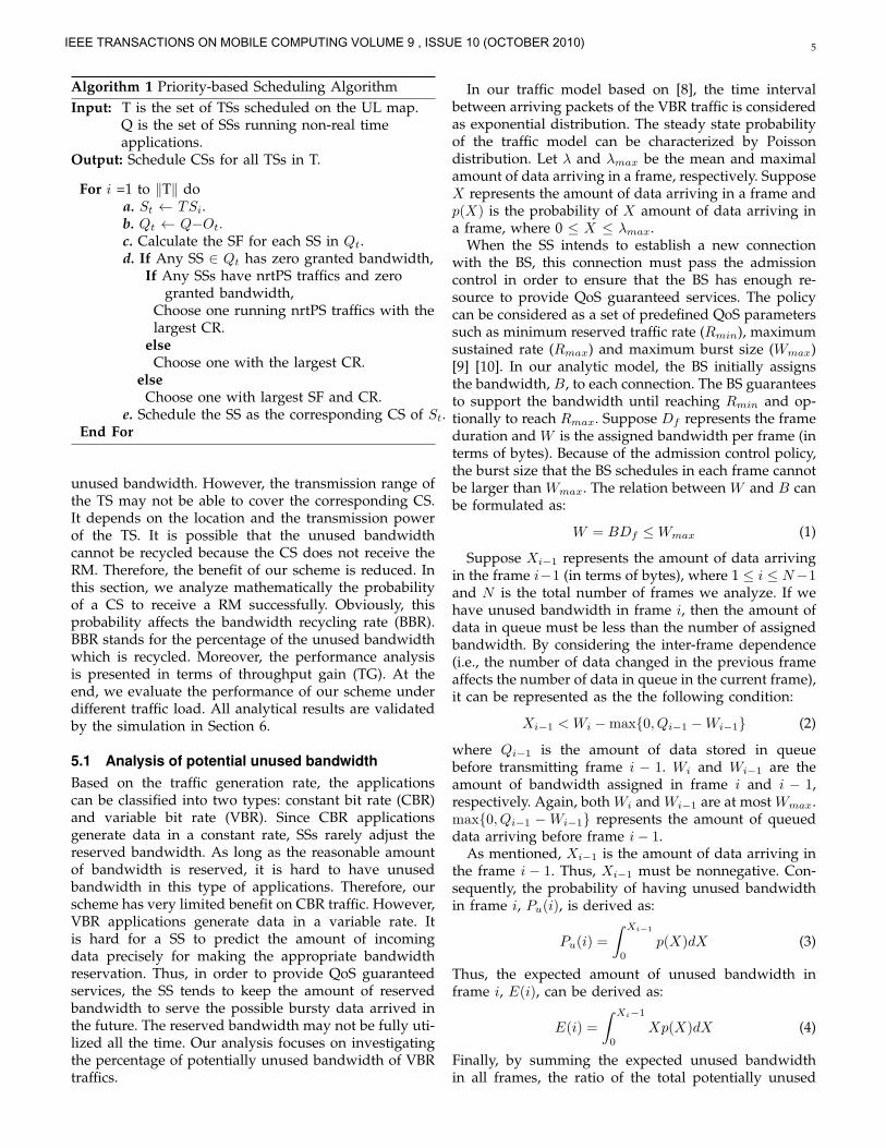
5.4 Overhead analysis of proposed schemeThe overhead introduced by our scheme resides in bothDL and UL subframes. In DL subframe, the separationand CL are considered as the overhead. As shown inFig. 1, the separation contains a broadcast CID (B-CID)and a SBV (0xFF). It costs 3 bytes of overhead (16 bitsfor B-CID and one byte for SBV). In addition, The CL iscomposed by the CL information elements (CL-IEs). TheCL-IE contains the basic CID of the CS. If the CS is notscheduled on the UL map, the burst profile and offsetmust be specified in the CL-IE of this CS. Therefore, thesize of CL-IE is at most the size of UL-MAP IE which is 7bytes defined in the IEEE 802.16 standard. In summary,the total overhead in a DL subframe can be concludedas:
OHDL ≤ 3 + 7BTS (27)
where BTS is the number of TSs scheduled on the ULmap.
According to the IEEE 802.16 standard, the SBV isinevitable when the SS has unused bandwidth. There-fore, only RMs are considered as the overhead in ULsubframe. Each TS transmits at most one RM in eachUL subframe. A RM comprises a generic MAC Header(GMH). The size of a GMH is 6 bytes defined in theIEEE 802.16 standard. Thus, the total overhead in an ULsubframe is calculated as:
OHUL ≤ 6BTS (28)
where BTS is the number of TSs scheduled on the ULmap. From equation (27) and (28), the total overheadintroduced by our scheme in a MAC frame is concludedas:
OH = OHDL +OHDL ≤ 3 + 7BTS + 6BTS (29)
5.5 Performance analysis of the proposed schemeunder different traffic loadThe traffic load in a network may vary dynamically.Thus, the network status can be classified into fourstages: light, moderate, heavy and fully loaded. Theperformance of the proposed scheme may be variant indifferent stages. We investigate the performance of our
IEEE TRANSACTIONS ON MOBILE COMPUTING VOLUME 9 , ISSUE 10 (OCTOBER 2010)
9
scheme in each stage. Suppose Ball represents the totalbandwidth supported by the BS. Assume Brt representsthe bandwidth reserved by real time connections andBRrt is the amount of additional bandwidth requestedby them via BRs. Similarly Bnrt represents the band-width assigned to non-real time connections and BRnrt
is the amount of additional bandwidth requested bythem. The investigation of our scheme in each stage isshown as follows. All investigations are validated viasimulation in Section 6.
1) Stage 1 (light load):This stage is defined as that the total demandingbandwidth of SSs is much less than the supply ofthe BS. The formal definition can be expressed as:
Ball ≫ Brt +Bnrt +BRrt +BRnrt
Since all BRs are granted in this stage, the BS sched-ules the CS randomly. Moreover, every SS receivesits desired amount of bandwidth. Therefore, forany given CS, Su, the probability to have datato recycle the unused bandwidth, derived fromequation (23), is small. It leads to low Pr (fromequation (24)). Therefore, the probability that theCS recycles the unused bandwidth successfully issmall and the throughput gain of our scheme is notsignificant.
2) Stage 2 (moderate load) :This network stage is defined as equal demand andsupply of bandwidth, i.e.,
Ball = Brt +Bnrt
In this stage, the BS can satisfy the existing demandbut does not have available resource to admitnew BRs. Since the currently desired bandwidth ofevery SS can be satisfied, the probability of CS torecycle the unused bandwidth (equation (23)) maybe higher than the stage 1 but still limited. Basedon equation (24), (25) and (26), the throughput gainis still insignificant.
3) Stage 3 (heavy load) :This stage is defined as that the BS can satisfy thedemand of real time connections, but does not haveenough bandwidth for the non-real time connec-tions. However, there are no rejected BRs in thisstage. We can express this in terms of formulationas:
Ball = Brt + κBnrt
where 0 ≤ κ < 1. Since the bandwidth for non-realtime connections has been shrunk, there is a highprobability that the CS accumulates non-real timedata in queue. It leads to higher Pr and Precycle.Thus, the throughput gain can be more significantthan Stage 1 and 2.
4) Stage 4 (full load) :This stage describes a network with the heaviesttraffic load. The difference between stage 3 and 4 isthat there are rejected BRs in stage 4. It means that
the probability of SSs accumulating non-real timedata in queue is much higher than the one in Stage3. Therefore, both Pr and Precycle are significantlyhigh. Our scheme can achieve the best performancein this stage.
5.6 TradeoffIn the IEEE 802.16 standard, the SS can adjust the amountof reserved bandwidth via BRs. In this subsection, weanalyze the performance between the proposed schemeand the scheme with BRs. However, there are no rulesspecified in the standard to tell the SS when to adjust theamount of reserved bandwidth. The objective of this pa-per is to improve the bandwidth utilization and systemthroughput. We define a case, named Case with BRs, thateach SS requests bandwidth for each connection in everyframe based on the queued data. The unicast pollingopportunity is given to each connection in every framefor making BRs.
In this case, in each frame, the SS always asks theamount of bandwidth as the number of data it will trans-mits. Therefore, the amount of unused bandwidth in thiscase is very limited. However, the SS has to transmita BR for every connection in every frame. Moreover,according to the IEEE 802.16 standard, the BR is made inper connection basis. Suppose there are m connectionsrunning on a SS. The SS has to send m BRs whichare 19m bytes (considering standard alone bandwidthrequests) in each frame. The overhead is dramaticallylarge in this case. Since the size of UL subframe is limitedin each frame, the throughput for transmitting real data(i.e., eliminating the overhead) may not be high. On theother hand, in the proposed scheme, the overhead thateach SS transmits is a constant (6 bytes for a RM) whichis much smaller than 19m bytes.
Since the CS needs to stay in active in order to listen toa possible RM from the corresponding TS, the CS cannotenter into sleep mode for power conservation. On theother hand, the probability of a CS to recycle the unusedbandwidth decreases if a sleeping SS is scheduled as theCS. Therefore, there is a tradeoff between the benefit ofthe proposed scheme and power conservation. If the CSdoes not enter into sleep mode, obviously, it can alwayslisten to a possible RM sent from the correspondingTS. On the other hand, it enters into sleep mode. TheSS switches its state between active and inactive. Asdescribed in the IEEE 802.16e standard, the BS has theinformation of available and unavailable period of theSS. Thus, the BS should avoid to schedule a SS which isin unavailable period as a CS. Furthermore, if the BSschedules an inactive SS as a CS, the whole networkstill operates successfully but the benefit of the proposedscheme is reduced.
6 SIMULATION RESULTS
Our simulation is conducted by using Qualnet 4.5 [11].In this section, we first present our simulation model
IEEE TRANSACTIONS ON MOBILE COMPUTING VOLUME 9 , ISSUE 10 (OCTOBER 2010)

10
followed by introducing the definition of performancemetrics used for measuring the network performance.The simulation results are shown as the third part ofthis section. At the end, we provide the validation oftheoretical analysis and simulation results.
6.1 Simulation ModelOur simulation model comprises one BS residing atthe center of geographical area and 50 SSs uniformlydistributed in the service coverage of BS. The parametersof PHY and MAC layers used in the simulation aresummarized in Table 1. PMP mode is employed in ourmodel. Since our proposed scheme is used to recycle theunused bandwidth in UL subframe, the simulation onlyfocuses on the performance of UL transmissions.
Parameters ValueNode number 51 (including BS)
Frame duration 20MSUL/DL subframe duration 10MS
Modulation scheme BPSK, QPSK, 16QAM, 64QAMDCD/UCD broadcast interval 5S
TTG/RTG 10USSS transition gap (SSTG) 4US
TABLE 1The system parameters used in our simulation
CBR is a typical traffic type used to measure the per-formance of networks in WiMAX research. However, itmay not be able to represent the network traffic existingin real life. Moreover, the IEEE 802.16 network aims toserve both data and multi-media applications. Most ofthe modern streaming videos are encoded by industrialstandards (e.g., H.264 or MPEG 4) which generate datain variant rates. In this research, we include VBR trafficsto illustrate H.264 and MPEG 4-encoded videos. In oursimulation, the traffic models for these streaming videosare based on related research [12] [13] [14]. Additionally,other commonly used VBR traffics such as HTTP andFTP applications are also included in our simulation. Thecharacteristics of traffic types are summarized in Table2.
In our simulation, each SS serves at least one and up to5 connections. Each connection serves one type of trafficwhich is mapped to the scheduling classes supportedin the IEEE 802.16 standards (i.e., UGS, rtPS, ertPS,nrtPS and BE). Table 2 enumerates all types of trafficand their corresponding scheduling classes used in oursimulation. In particular, all VBR traffic in our simulationis considered as ON/OFF traffic. We fix the mean datarate of each application but make the mean packet sizerandomly selected from 512 to 1024 bytes. Thus, themean packet arrive rate can be determined based on thecorresponding mean packet size. As mentioned earlier,the size of each packet is modeled as Poisson distributionand the packet arrival rate is modeled as exponentialdistribution. For example, in order to simulate the net-work traffics more realistically, the start time of each
connection is randomly selected from 0 to 15th second.Moreover, the real time connection stops to generate datafrom 75th to 100th second. It is for investigating theperformance of our scheme when the large amount ofunused bandwidth is available. Therefore, the numberof active connections (the connections which are trans-mitting data) may be different during the simulation.
Application VoIP Multimedia HTTP FTPTraffic type CBR VBR VBR VBR
Scheduling class UGS rtPS BE nrtPSStart Time(sec.) m* m* m* m*End Time(sec.) n* n* 100 100
Mean Packet Size 512 z* z* z*Mean Bit Rate 12.2kbps 2Mbps 2kbps 50Mbps
Max burst Size (Byte) 31 7.5k 10 1500kPacket Size Fixed P* P* P*
Packet Arrival Rate Fixed E* E* E*Note: m* is a random number between 0 and 15.
n* is a random number between 75 and 100.z* is a random number between 512 and 1024 bytesP* stands for Poisson distributionE* stands for Exponential distribution
TABLE 2The traffic model used in the simulation
6.2 The Performance MetricsThe simulation for evaluating the performance of theproposed scheme is based on the three metrics:
1) Throughput gain (TG):It represents the percentage of throughput whichis improved by implementing our scheme. Theformal definition can be expressed as:
TG =Trecycle − Tno recycle
Tno recycle
where Trecycle and Tno recycle represent thethroughput with and without implementing ourscheme, respectively. The higher TG achievedshows the higher performance that our schemecan make.
2) Unused bandwidth rate (UBR):It is defined as the percentage of the unused band-width occupied in the total granted bandwidth inthe system without using bandwidth recycling. Itcan be defined formally as:
UBR =Bunused bw
Btotal bw
where Bunused bw and Btotal bw are the unusedbandwidth and total allocated bandwidth, respec-tively. The UBR shows the room which can beimproved by our scheme. The higher UBR meansthe more recycling opportunities.
3) Bandwidth recycling rate (BRR):It illustrates the percentage of bandwidth which isrecycled from the unused bandwidth. The percent-age can be demonstrated formally as:
BRR =Brecycled
Bunused bw
IEEE TRANSACTIONS ON MOBILE COMPUTING VOLUME 9 , ISSUE 10 (OCTOBER 2010)

11
0 10 20 30 40 50 60 70 80 90 100 1100
10
20
30
40
50
60
70
80
UB
R (%
)
Simulation Time (Second)
Fig. 8. Simulation results of UBR
where Brecycled is the bandwidth recycled fromBunused bw. BRR is considered as the most criticalmetric since it directly reveals the effectiveness ofour scheme.
6.3 Simulation Results
Fig. 8 presents the percentage of the unused bandwidthin our simulation traffic model (i.e., UBR). It shows theroom of improvement by implementing our scheme.From the simulation results, we conclude that the av-erage UBR is around 38%. In the beginning, the UBRgoes down. It is because each connection still requestsbandwidth from the BS. As time goes on, the UBRstarts to increase when the connection has received therequested bandwidth. After 75th second of simulationtime, UBR increases dramatically due to the inactivityof real time connections. The purpose to have inactivereal time connections is to simulate a network withlarge amount of unused bandwidth and evaluate theimprovement of the proposed scheme in such networkstatus. The evaluation is presented in the later of thissection.
The simulation results of recycling rate are presentedin Fig. 9. From the figure, we observe that the recy-cling rate is very close to zero at the beginning of thesimulation. It is because that only a few connectionstransmit data during that time and the network hasa light load. Therefore, only few connections need torecycle the unused bandwidth from others. As time goeson, many active connections join in the network. Theavailable bandwidth may not be able to satisfy the needsof connections. Therefore, there is a high probability thatthe CS recycles the unused bandwidth. It leads a higherBRR.
Fig. 10 shows the total bandwidth demand requestedby SSs during the simulation. In the figure, the dashedline indicates the system bandwidth capacity. During thesimulation, the BS always allocates the bandwidth tosatisfy the demand of real time connections due to theQoS requirement. Therefore, the amount of bandwidth
0 10 20 30 40 50 60 70 80 90 100 1100
10
20
30
40
50
BR
R (%
)
Simulation Time (Second)
Fig. 9. Simulation results of BRR.
0 20 40 60 80 1000
50000
100000
150000
200000
250000
300000
350000
400000
Dem
and
(Byt
es/F
ram
e.)
Simulation Time (Sec.)
Demand Capacity
Fig. 10. Total Bandwidth Demand
allocated to non-real time connections may be shrunk. Atthe same time, the new non-real time data are generated.Therefore, the non-real time data are accumulated in thequeue. It is the reason that the demand of bandwidthkeeps increasing.
Fig. 11 presents the results of TG calculated from thecases with and without our scheme. In the figure, the TGis very limited at the beginning of the simulation, whichis similar to the results of the BRR. It shows Stage 1and 2 described in section 5 that there is no significantimprovement on our scheme when the network load islight. As the traffic increases, the TG reaches around15 to 20%. It is worth to note that the TG reachesaround 20% at 35th second of the simulation time. Itmatches the time that the bandwidth demand reachesthe system capacity shown in Fig. 10. Again, it confirmsour early observation (Stage 3 and 4 in section 5) thatthe proposed scheme can achieve higher TG when thenetwork is heavily loaded. After the 75th second, theTG increases dramatically. It shows that our scheme canhave significant improvement on TG when the largeamount of unused bandwidth is available.
We also investigate the delay in the cases with andwithout our scheme. By implementing our scheme, the
IEEE TRANSACTIONS ON MOBILE COMPUTING VOLUME 9 , ISSUE 10 (OCTOBER 2010)

12
0 10 20 30 40 50 60 70 80 90 100 1100
10
20
30
40
50
60
TG (%
)
Simulation Time (Second)
Fig. 11. Simulation results of TG
0 20 40 60 80 100
0
5
10
15
20
25
Thou
ghpu
t (M
bps)
Simulation Time (sec.)
Our scheme with BRs
Fig. 12. Comparison with the case with BRs
average delay is improved by around 19% comparingto the delay without using our scheme. It is due tothe higher overall system throughput improved by ourscheme.
From the simulation results shown above, we concludethat the proposed scheme can not only improve thebandwidth utilization and throughput but also decreasethe average delay. Moreover, the scheme reaches thehigher performance when the network is heavily loaded.This validates our performance analysis shown in stage1 to 4 in Section 5.
Fig. 12 shows the throughput comparison between ourscheme and Case with BRs defined in Section 5.6. Fromthe figure, we obtain that the throughput of Case withBRs can maintain higher throughput than the proposedscheme in most of time but the achievable throughputof our scheme is higher. It is because the SS in theformer case always requests bandwidth based on thenumber of queued data. However, the BS has to reservesufficient amount of bandwidth for BRs. Therefore, itlimits the number of bandwidth for data transmissions.Additionally, this comparison is based on the proposedscheduling algorithm, named Priority-based Schedulingalgorithm. The throughput of the proposed scheme is
enhanced further by algorithms proposed later in Section7.
6.4 Theoretical Analysis V.S. Simulation ResultsIn this subsection, we validate the theoretical analysisand simulation results of UBR and RMs coverage. Tovalidate the UBR, we focus on the multimedia trafficspecified in Table 2. The simulation model comprisesone BS and one SS. The SS only serves one multimediatraffic specified. The simulation result shows that theUBR is around 35.99%. Moreover, the theoretical resultcalculated by equation (5) is about 35.29%. It is closed tothe simulation result.
For validating the coverage of RMs, we employ thetypical parameters used in IEEE 802.16 networks in ourtheoretical analysis. From equation (20), the theoreticalpercentage of RMs coverage is from 42 to 58%. Addi-tionally, the result from our simulation is 48.7% whichis within the range of our theoretical result.
To analyze the simulation results more profoundly, weinvestigate the two factors that the unused bandwidthfail to be recycled: 1) CSs cannot receive RMs sentby their corresponding TSs. 2) CSs do not have datato recycle the unused bandwidth while receiving RMs.According to our simulation results, the probability offailing to recycle the unused bandwidth is around 61.5%which includes both factors described above. By doingfurther investigation, we find that about 51.3% of failuresis because the CS cannot receive a RM form the corre-sponding TS. The rest of failures, about 10.2%, are causedby no data to be transmitted while the CS receives a RM.Based on this observation, three scheduling algorithmsare proposed in Section 7 to mitigate the affection ofthese factors for improving the recycling performance.
7 FURTHER ENHANCEMENT
As our investigation, one of the factors causing recyclingfailures is that the CS does not have data to transmitwhile receiving a RM. To alleviate this factor, we proposeto schedule SSs which have rejected BRs in the last framebecause it can ensure that the SS scheduled as CS hasdata to recycle the unused bandwidth. This schedulingalgorithm is called Rejected Bandwidth Requests First Al-gorithm (RBRFA). It is worth to notice that the RBRFA isonly suitable to heavily loaded networks with rejectedBRs sent from non-real time connections (i.e., nrtPS orBE). Notice that only rejected BRs sent in the last frameare considered in the RBRFA for scheduling the currentframe. The RBRFA is summarized in Algorithm 2.
The BS grants or rejects BRs based on its availableresource and scheduling policy. In RBRFA, if the BSgrants partially amount of bandwidth requested by aBR, then this BR is also considered as a rejected BR.Similar to Algorithm 1, Ot represents the set of SSs whichtransmission period overlaps with the TS, St, in QR.All SSs in Qt are considered as possible CSs of St. Arejected BR shows that the SS must have extra data to
IEEE TRANSACTIONS ON MOBILE COMPUTING VOLUME 9 , ISSUE 10 (OCTOBER 2010)

13
Algorithm 2 Rejected Bandwidth Requests First Algo-rithmInput: T is the set of TSs scheduled on the UL map.
QR is the set of SSs which have rejected BRssent from non-real time connections in the lastframe.
Output: Schedule a CS for each TS in T.
For i =1 to ∥T∥ doa. St ← TSi.b. Qt ← QR−Ot.c. Randomly pick a SS ∈ Qt as the
corresponding CS of St
End For
be transmitted in the next frame and no bandwidth isallocated for these data. The RBRFA schedules those SSsas CSs on the CL, so the probability to recycle the unusedbandwidth while the CS receives the RM is increased.
The other factor that may affect the performance ofbandwidth recycling is the probability of the RM to be re-ceived by the CS successfully. To increase this probability,a scheduling algorithm, named history-Based SchedulingAlgorithm (HBA), is proposed. The HBA is summarizedin Algorithm 3. For each TS, the BS maintains a list,
Algorithm 3 History-Based Scheduling AlgorithmInput: T is the set of TSs scheduled on the UL map.
Q is the set of SSs running non-real timeapplicationsBL is the set of black lists of TSs.
Output: Schedule a CS for each TS in T.
For i =1 to ∥T∥ doa. St ← TSi.b. Qt ← Q−Ot −BLi
c. Randomly pick a SS ∈ Qt as thecorresponding CS of St
d. IF the scheduled CS did not transmit dataor SBVThen put this CS in the BLi
End For
called Black List (BL). The basic CID of a CS is recordedin the BL of the TS if this CS cannot receive RMs sentfrom the TS. According to our protocol, the CS transmitsdata or pad the rest of transmission interval if a RM isreceived. The BS considers that a CS cannot receive theRM from its corresponding TS if the BS does not receiveeither data or padding information from the CS. Whenthe BS schedules the CS of each TS in future frames, theBS only schedules a SS which is not on the BL of the TSas the CS. After collecting enough history, the BL of eachTS should contains the basic CID of all SSs which cannotreceive the RM sent from the TS. By eliminating thoseSS, the BS should have high probability to schedule a CSwhich can receive the RM successfully. Therefore, HBA
can increase the probability of scheduling a SS which isable to receive the RM as the CS.
To support the mobility, the BL of each TS shouldbe updated periodically. Moreover, the BS changes theUL burst profile of the SS when it cannot listen to theSS clearly. There are two possible reasons which maymake the BS receive signals unclearly: 1) the SS hasmoved to another location. 2) the background noise isstrong enough to interfere the data transmissions. Sincethose two factors may also affect the recipient of RMs,therefore, the BL containing this SS should be updatedas well.
The two algorithms described above focus on mitigat-ing each factor that may cause the failure of recycling.The RBRFA increases the probability that the CS has datato transmit while receiving the RM. The HBA increasesthe probability that the CS receives the RM. However,none of them can alleviate both factors at the same time.By taking the advantages of both RBRFA and HBA, analgorithm called Hybrid Scheduling Algorithm (HSA) isproposed. HSA can increase not only the probability ofCSs to transmit data while receiving the RM but also theprobability of CSs to receive the RM. The detail of HSAis summarized in Algorithm 4
Algorithm 4 Hybrid Scheduling AlgorithmInput: T is the set of TSs scheduled on the UL map.
QR is the set of SSs which have rejected BRssent for non-real time applications.BL is the set of black lists of TSs.
Output: Schedule a CS for each TS in T.
For i =1 to ∥T∥ doa. St ← TSi.b. Qt ← QR−Ot −BLi
c. Randomly pick a SS ∈ Qt as thecorresponding CS of St
d. IF the scheduled CS did not transmit dataor SBVThen put this CS in the BLi
End For
When the BS schedules the CS for each TS, only theSS with rejected BRs is considered. As mentioned before,it increases the probability of CSs to transmit data whilereceiving the RM. Moreover, the BS maintains a BL foreach TS. It can screen out the SSs which can not receivethe RM so that those SS cannot be scheduled as theCSs. The probability of receiving RMs can be increased.Again, the BL of each TS should be updated periodicallyor when the UL burst profile of the SS has been changed.By considering those two advantages, HSA is expectedto achieve higher TG and BBR comparing to RBRFA andHBA.
8 SIMULATION RESULTS OF ENHANCEMENTThe simulation model for evaluating these schedulingalgorithms is same as the model presented in section 6.
IEEE TRANSACTIONS ON MOBILE COMPUTING VOLUME 9 , ISSUE 10 (OCTOBER 2010)

14
0 10 20 30 40 50 60 70 80 90 100 110-50
0
50
100
150
200
TG (%
)
Simulation Time (Second)
PSA HBA RBRFA HSA
Fig. 13. Simulation results of TG among all schedulingalgorithms
The BS is located at the center of a geographical area.There are 50 SSs uniformly distributed in the servicecoverage of BS. Each SS serves at least one and up to5 connections. The simulation results of TG is shown inFig. 13. Before the 15th second of simulation time, theTG may be negative. It means the throughput withoutrecycling is higher than the throughput with recycling.It is because the applications of each SS start to generatedata randomly in the first 15 seconds of simulation time.As described before, the PSA shown as Algorithm 1can achieve averagely 20% of throughput. The RBRFAcan further improve the throughput to 26% because ofincreasing the chance of transmitting data while the CSreceives the RM. Moreover, the HBA can have a greaterimprovement on TG to 30%. It shows that the factor ofmissing RMs causes more failures of recycling than thefactor of no data transmissions while the CS receivesthe RM does. This result consists with our observationin section 6 that the probability of missing RMs is higherthan the probability that the CS cannot recycle the un-used bandwidth due to the lack of data to be transmitted.Moreover, HSA achieves the best performance on TG(averagely 45% improvement) since it combines bothadvantages of HBA and RBRFA.
The comparison of BRR is shown in Fig. 14. The resultsconsist with the results of TG shown above. The HSA hasthe highest BBR. Moreover, the HBA achieves the higherBBR than the RFA does. Additionally, it is worth notingthat the BRR of the RRFA can not be more than 50% evenwhen the network is fully loaded. It is because, basedon our investigation in section 6, there is only 48.7% ofprobability that a CS can receive a RM successfully.
The comparison of the total bandwidth demand isshown in Fig 15. From the figure, the increasing speedof bandwidth demand from low to high is HSA, HBA,RBRFA, PSA and No Recycling. This result matches theresult of TG. It is because that there are fewer dataaccumulated in the queue when the TG is higher. It leadsto less bandwidth demand.
Due to the improvement of throughput, the average
0 10 20 30 40 50 60 70 80 90 100 1100
10
20
30
40
50
60
70
80
90
BR
R (%
)
Simulation Time (Second)
PSA RBRFA HBA HSA
Fig. 14. Simulation results of BBR among all schedulingalgorithms
0 20 40 60 80 1000
50000
100000
150000
200000
250000
300000
350000
400000
Ban
dwid
th D
eman
d (B
ytes
/Fra
me.
)
Simulation Time (Sec.)
PSA RBRFA HBA HSA NoRecycling
Fig. 15. Simulation results of bandwidth demand
delay is also improved. The summary of delay improve-ment is shown in Fig. 16. Similar to the simulation resultsof TG and BRR. The HSA has the best improvement ondelay due to the highest throughput it achieves.
9 CONCLUSIONS
Variable bit rate applications generate data in variantrates. It is very challenging for SSs to predict the amountof arriving data precisely. Although the existing methodallows the SS to adjust the reserved bandwidth via
HBA HSA PSA RBRFA0
10
20
30
40
Del
ay Im
prov
emen
t (%
)
Scheduling Algorithm
Fig. 16. Simulation results of delay improvement
IEEE TRANSACTIONS ON MOBILE COMPUTING VOLUME 9 , ISSUE 10 (OCTOBER 2010)

15
bandwidth requests in each frame, it cannot avoid therisk of failing to satisfy the QoS requirements. More-over, the unused bandwidth occurs in the current framecannot be utilized by the existing bandwidth adjustmentsince the adjusted amount of bandwidth can be appliedas early as in the next coming frame. Our researchdoes not change the existing bandwidth reservationto ensure that the same QoS guaranteed services areprovided. We proposed bandwidth recycling to recycle theunused bandwidth once it occurs. It allows the BS toschedule a complementary station for each transmissionstations. Each complementary station monitors the entireUL transmission interval of its corresponding TS andstandby for any opportunities to recycle the unusedbandwidth. Besides the naive priority-based schedul-ing algorithm, three additional algorithms have beenproposed to improve the recycling effectiveness. Ourmathematical and simulation results confirm that ourscheme can not only improve the throughput but alsoreduce the delay with negligible overhead and satisfythe QoS requirements.
REFERENCES[1] IEEE 802.16 WG,”IEEE Standard for Local and Metropolitan Area
Network Part 16: Air Interface for Fixed Boardband WirelessAccess Systems” IEEE Std 802.16-2004 p.1 - p.857
[2] IEEE 802.16WG, ”IEEE standard for local and metropolitan areanetworks part 16: Air interface for fixed and mobile broadbandwireless access systems, Amendment 2,” IEEE 802.16 Standard,December 2005.
[3] Jianhua He, Kun Yang and Ken Guild ”A Dynamic BandwidthReservation Scheme for Hybrid IEEE 802.16 Wireless Networks”ICC’08 p.2571-2575.
[4] Kamal Gakhar, Mounir Achir and Annie Gravey, ”Dynamic re-source reservation in IEEE 802.16 broadband wireless networks”,IWQoS, 2006. p.140-148
[5] J. Tao, F. Liu, Z. Zeng, and Z. Lin, Throughput enhancement inWiMax mesh networks using concurrent transmission, In Proc.IEEE Int. Conf. Wireless Commun., Netw. Mobile Comput., 2005, p.871V874.
[6] Xiaofeng Bai, Abdallah Shami and Yinghua Ye ”Robust QoSControl for Single Carrier PMP Mode IEEE 802.16 Systems”,IEEETRANSACTIONS ON MOBILE COMPUTING, VOL. 7, NO. 4,APRIL 2008, p.416-429
[7] Eun-Chan Park, Hwangnam Kim, Jae-Young Kim, Han-Seok Kim”Dynamic Bandwidth Request-Allocation Algorithm for Real-timeServices in IEEE 802.16 Broadband Wireless Access Networks”,INFOCOM 2008,p.852 - 860
[8] Thomas G. Robertazzi ”Computer Networks and Systems:Theoryand Performance Evaluation.” Springer-Verlag 1990
[9] Kamal Gakhar, Mounir Achir and Annie Gravey, ”How ManyTraffic Classes Do We Need In WiMAX?,” WCNC 2007, p.3703-3708
[10] Giuseppe Iazeolla, Pieter Kritzinger and Paolo Pileggi, ”Mod-elling quality of service in IEEE 802.16 networks,”SoftCOM 2008.p.130-134
[11] Qualnet,http://www.scalable-networks.com/products/developer/new in 45.php
[12] Frank H.P. Fitzek, Martin Reisslein, ”MPEG–4 and H.263 VideoTraces for Network Performance Evaluation”, IEEE Network, Vol.15, No. 6, p.40-54, November/December 2001
[13] Patrick Seeling, Martin Reisslein, and Beshan Kulapala, ”NetworkPerformance Evaluation Using Frame Size and Quality Traces ofSingle-Layer and Two-Layer Video: A Tutorial”, IEEE Communica-tions Surveys and Tutorials, Vol. 6, No. 2 p.58-78, Third Quarter 2004
[14] Geert Van der Auwera, Prasanth T. David, and Martin Reisslein,”Traffic and Quality Characterization of Single-Layer VideoStreams Encoded with H.264/AVC Advanced Video Coding Stan-dard and Scalable Video Coding Extension”, IEEE Transactions onBroadcasting Vol. 54, No. 3 p.698-718 September 2008
David Chuck received the BS degree in AppliedMath from Tatung University, Taiwan in 2004and the MS degree in Computer Science fromIllinois Institute of Technology in 2007. He iscurrently working toward his Ph.D. degree inComputer Engineering at Iowa State University.His research interests include wireless network-ing, network virtualization, resource allocationand game theoretical study of networks. He alsoworked as a research intern in NTT NetworkInnovation Labs at Yokosuka, Japan in 2009.
J. Morris Chang is an associate professor atIowa State University. He received the Ph.D. de-gree from North Carolina State University. His in-dustrial experience includes Texas Instruments,and AT& T Bell Labs. He received the UniversityExcellence in Teaching Award at Illinois Instituteof Technology in 1999. His research interestsinclude: wireless networks, and computer sys-tems. Currently, he is an editor of Journal ofMicroprocessors and Microsystems and IEEE ITProfessional. He is a senior member of IEEE.
IEEE TRANSACTIONS ON MOBILE COMPUTING VOLUME 9 , ISSUE 10 (OCTOBER 2010)
![IEEE 802.11 and 802.16 Cooperation Within Multi … 802.11 and 802.16 Cooperation Within Multi-Radio Stations 527 upgrades to the MAC of the 802.16 base station in [15]. These updates](https://img.pdfslide.us/doc/110x75/5b0cb85a7f8b9a02508c9b9a/ieee-80211-and-80216-cooperation-within-multi-80211-and-80216-cooperation-within.jpg)